

Page 1
Page 2

© 2003 Compex Systems Pte Ltd
All Rights Reserved
This document contains information, which is protected by copyright. Reproduction,
adaptation or translation without prior permission is prohibited, except as allowed under
the copyright laws.
Trademark Information
®
Compex
, ReadyLINK® and MicroHub® are registered trademarks of Compex, Inc.
Microsoft Windows and the Windows logo are the trad emarks o f Micros oft Corp. NetWare
is the registered trademark of Novell Inc. All other brand and product names are
trademarks or registered trademarks of their respective owners.
Notice: Copyrights © 2003 by Compex, Inc. All rights reserved. Reproduction, adaptation,
or translation without prior permission of Compex, Inc. is prohibited, except as allowed
under the copyright laws.
Manual Revision by Kee
Manual Number: U-0397-V1.1C Version 1.1, October 2003
Disclaimer
Compex, Inc. provides this manual without warranty of any kind, either expressed or
implied, including but not limited to the implied warranties of merchantability and fitness
for a particular purpose. Compex, Inc. may make improvements and/or changes to the
product and/or specifications of the product described in this manual, without prior
notice. Compex, Inc will not be liable for any technical inaccuracies or typographical
errors found in this guide. Changes are periodically made to the information contained
herein and will be incorporated into later versions of the manual. The information
contained is su bject to change without pr ior notice.
Your Feedback
We value your feedback. If you find any errors in this user’s manual, or if you have
suggestions or comments, we would like to hear from you. Please contact us at:
Fax: (65) 62809947
Email:
feedback@compex.com.sg
Firmware
Please note that this User’s Manual is written based on NetPassage WPE54G Firmware
Release 1.00.
FCC NOTICE
This device has been tested and found to comply with the limits for a Class B digital
device, pursuant to Part 15 of the FCC Rules. These limits are designed to provide
reasonable protection against harmful interference in a residential installation. This device
generates, uses and can radiate radio frequency energy and, if not installed and used in
accordance with the instructions, may cause harmful interference to radio
communications. However, there is no guarantee that interference will not occur in a
particular installation. If this device does cause harmful interference to radio or television
i
Page 3

reception, the user is encouraged to try to correct the interference by one or more of the
following measures:
Reorient or relocate the receiving antenna.
Connect the compu ter into an outlet on a cir cuit different from that to which
the receiver is connected.
Increase the separation between the computer and receiver.
Consult the dealer or an experienced radio/TV technician for help.
Caution: Any changes or modifications not expressly approved by the grantee of this
device could void the user's authority to operate the equipment.
FCC Compliance Statement: This device complies with Part 15 of the FCC Rules. Operation
is subject to the following two conditions:
This device may not cause harmful interference, and
This device must accept any interference received, including interference that
Declaration of Conformity
Compex, Inc. declares the following:
Product Name: Compex NetPassage WPE54G 54Mbps Wireless-G Access Point
Model No.: NetPassage WPE54G conforms to the following Product Standards:
This device complies with the Electromagnetic Compatibility Directive (89/336/EEC) issued
by the Commission of the European Community. Compliance with this directive implies
conformity to the following European Norms (in brackets are the equivalent international
standards.)
Electromagnetic Interference (Conduction and Radiation): EN 55022 (CISPR 22)
Electromagnetic Immunity: EN 55024 (IEC61000-4-2,3,4,5,6,8,11)
Power Line Harmonics: EN 61000-3-2 (IEC610000-3-2)
Power Line Flicker: EN 61000-3-3 (IEC610000-3-3)
Therefore, this product is in conformity with the following regional standards:
FCC Class B ⎯ following the provisions of FCC Part 15 directive;
CE Mark ⎯ following the provisions of the EC directive.
This Class B digital apparatus complies with Canadian ICES-003.
may cause undesired operation.
ii
Page 4

About This Document
The product described in this document, Compex 54Mbps Wireless-G Access Point
series, NetPassage WPE54G, is a licensed product of Compex Systems Pte Ltd.
Information provided: This document provides an overview of the key features and
applications of the WPE54G. It also contains instructions for installing, configuring
and using the Compex NetPassage WPE54G.
Audience: This manual is intended for both Network Administrators and end-users
who possess a basic knowledge of networking structures and protocols.
Assumptions: Procedures listed in the document are intended for Microsoft Windows
users. If you are running a different operating system, you may need to refer to your
operating system’s documentation for networking instructions.
How to use this document: If you want to get started without having to read
everything
Skip to Chapter 3 for the hardware setup procedure
Follow Chapter 4 for logging onto the configuration interface
Tag on with Chapter 5 for basic configurations
Advanced users can pursue further configuration with Chapter 6
The Table of Contents will guide you to specific topics.
Conventions: The Compex 54Mbps Wireless-G Access Point NetPassage WPE54G
is often referred to as WPE54G. Here is a list of icons used throughout the manual:
!
This symbol characterises sections meant for advanced users or
X
pert
e
eXpert
Technology Primer
This symbol highlights exclusive features found on this Compex
exclusive!
This symbol alerts the user of an important noti ce to be heeded. The
user is advised to read instructions carefully before proceeding
further.
specific features meant for exceptional non-standard applications.
The user is assumed to have sufficient relevant network knowledge to
carry out the necessary configuration or understand the information
given.
This symbol suggests that the user find additional networking
information from our unique Technology Primer documents included
on the Product CD. The documents explain specific network
concepts, Compex-exclusive features and provide illustrated
walkthroughs for common networking scenarios.
product or on Compex’s family of products.
iii
Page 5

CHAPTER 1: INTRODUCTION............................................................. 1
CHAPTER 2: GETTING TO KNOW YOUR PRODUCT ........................... 3
Key features.................................................................................................. 3
Security Features.......................................................................................... 4
The NetPassage WPE54G Package............................................................ 5
Schematic Overview of the NetPassage WPE54G...................................... 5
When to use which mode ............................................................................. 6
The Access Point Mode........................................................................................ 6
The Access Point Client Mode..............................................................................7
The Gateway Mode...............................................................................................8
The Wireless Routing Client Mode.......................................................................9
The Wireless Ethernet Adapter Mode...................................................................9
CHAPTER 3: HARDWARE INSTALLATION ........................................ 10
CHAPTER 4: WEB-BASED CONFIGURATION INTERFACE................ 11
Log-in to web-based configuration interface............................................... 11
1. Through the uConfig utility ............................................................................11
2. Through your web browser............................................................................12
CHAPTER 5: BASIC CONFIGURATION ............................................. 13
Basic configuration......................................................................................13
Show Link Information – a helpful feature.................................................. 17
Using the SYSTEM TOOLS Menu.............................................................. 18
System Identity....................................................................................................18
Set System’s Clock..............................................................................................19
Firmware Upgrade.............................................................................................20
Save or Reset Settings.........................................................................................21
Reboot System ....................................................................................................23
Change Password...............................................................................................24
Logout ................................................................................................................25
Using the HELP menu................................................................................ 26
Get Technical Support........................................................................................26
About System......................................................................................................27
CHAPTER 6: ADVANCED CONFIGURATION ..................................... 28
Management Port Setup............................................................................. 28
SNMP Setup............................................................................................... 31
WEP Encryption.......................................................................................... 32
IEEE 802.1X/RADIUS Setup...................................................................... 34
WAN Setup................................................................................................. 37
Wireless Setup - The Wireless Distributed System (WDS)........................ 42
Page 6

Star Configuration Infrastructure Network........................................................42
Chain Configuration Infrastructure Network.....................................................43
Parallel Broadband.....................................................................................47
Load balancing...................................................................................................47
Fail-Over Redundancy.......................................................................................47
Ease of implementation ......................................................................................47
Wireless Setup – The Wireless Pseudo VLAN........................................... 50
Wireless Pseudo VLAN Per Node.......................................................................50
Wireless Pseudo VLAN Per Group.....................................................................51
Tag VLAN...........................................................................................................55
NAT............................................................................................................. 58
The De-Militarised Zone (DMZ) Host................................................................59
The Port-Forwarding Virtual Server..................................................................60
The IP-Forwarding Virtual Server.....................................................................63
Routing........................................................................................................ 65
Dynamic Routing................................................................................................67
IP Filtering................................................................................................... 69
Remote Management................................................................................. 73
Scan for Site Survey................................................................................... 74
Data collected in AP mode.............................................................................74
Data collected in wireless client mode.........................................................74
APPENDIX A: CONFIGURING FOR NETWORK ACCESS.................... 76
Adding TCP/IP network protocol for Microsoft Windows 98/98SE/ME....... 76
Configuring Dynamic IP address allocation................................................ 78
Microsoft Windows 98/98SE/ME .......................................................................78
Configuring Static IP address allocation..................................................... 79
Configuring Static IP address allocation..................................................... 80
Microsoft Windows 98/98SE/ME .......................................................................80
Configuring Wireless Network Settings...................................................... 83
Microsoft Windows XP.......................................................................................83
APPENDIX B: TROUBLESHOOTING ................................................. 85
Solutions to Common Problems................................................................. 85
APPENDIX C: FREQUENTLY ASKED QUESTIONS............................ 88
Answers to Frequently Asked Questions.................................................... 88
APPENDIX D: GLOSSARY OF TERMS............................................... 89
APPENDIX E: TECHNICAL SPECIFICATIONS ................................... 94
APPENDIX F: TECHNICAL SUPPORT INFORMATION........................ 96
Page 7
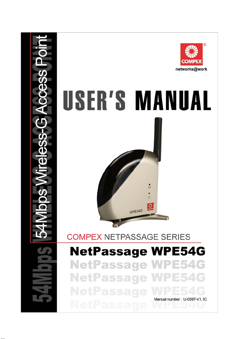
Chapter 1 Introduction
Chapter 1: Introduction
hank you for purchasing the Compex
NetPassage WPE54G 54 Mbps Wireless-G
Access Point! We are committed to deliver,
T
high-performance, feature-rich, user-friendly and costeffective network access point device. You will soon
be discovering more about a product which we have
proudly developed.
The Compex NetPassage WPE54G is a highperformance IEEE 802.11g-compliant wireless access
point which supports industry-leading security
standards. It features PRISM Nitro
which allows you to achieve up to 50% higher
throughput in pure wireless “G” networks and 300%
better throughput in mixed mode environments.
Advanced Features
New 54Mbps Wireless-G
Turbo-charge your wireless
Secure your data transmissions
Read on to find out more about
these features!
meet and even exceed your expectations of a
TM
In addition to fast performance, the WPE54G
supports IEEE 802.1x authentication and
128-bits Wired Equivalent Privacy (WEP)
802.11g
networks with
Technology for 50% greater
throughput in “G” and 300% in
mixed networks consisting “B”
and “G” devices.
with
and
Encryption!
5X faster than 802.11b!
PRISM Nitro™
IEEE 802.1x authentication
64/128-bits WEP
64/
encryption as a guarantee of peace of mind when
it comes to transmitting confidential data.
Moreover, the WPE54G supports Compex’s
unique Wireless Pseudo VLAN feature to
provide further privacy and security among
wireless users in the network or hotspot.
What makes the WPE54G more than great is that
may be operated in up to 5 different modes!
it
The flexibility of its functions, as Access Point,
Access Point
Client or Wireless Ethernet Adapter, makes it
suitable for nearly all kinds of network
applications that you may require.
Technology
Client, Gateway, Wireless Routing
1
Page 8

Chapter 1 Introduction
In the Access Point mode operation, the WPE54G
allows you to perform wireless to wired Ethernet
bridging, linking up your wired network with the
wireless clients. On the other hand, you may also
configure the WPE54G as an Access Point Client so
as to set up a wireless bridge between two wired
LANs. The Gateway mode offers a unique setup,
allowing you to share a broadband Internet access with
up to 253 wireless clients using NAT technology.
This feature-rich mode lets you configure a fullfledged gateway with built-in DHCP server, and
further supports Virtual Servers based on IP and Port
Forwarding, De-Militarized Zone, Packet Filtering and
more!
The Compex NetPassage WPE54G presents the most
comprehensive features that will meet your highest
expectations as a network user.
Compex Exclusive!
Enhance your wireless
network privacy with
Wireless Pseudo VLAN!
Operate the WPE54G in
Quickly access your
Read on to find out more
about these features!
5 advanced modes
up to
for any kind of network
operations!
network device’s
administration setup with
uConfig!
2
Page 9

Chapter 2
Getting to know your product
Chapter 2: Getting to Know Your Product
The Compex NetPassage WPE54G has been designed for high performance and offers
a rich suite of features, with which you should acquaint yourself in order to exploit
your WPE54G’s full potential.
Key features
Compatible with IEEE 802.11g and IEEE 802.11b standards
Adopting the 802.11g standard, the Compex NetPassage WPE54G provides you the fastest
wireless a ccess within your off ice or home network. Since it is fully backward compatible
with 802.11b, you can safeguard your existing network investments.
Featuring PRISM NitroTM Technology
PRISM NitroTM Technology is incorporated into the Com pex NetPa ssage WPE54G so as to
reduce d ata packet collisions when using mixed “G” and “B” wireless network devices. By
employing an advanced algorithm for burst mode transmission, the Compex NetPassage
WPE54G can achieve up to 50% higher throughput for “G” networks and up to 300%
increased throughput in mixed mode operation situations.
Read more on this at
Static IP, Dynamic IP, PPP and PPTP over Ethernet WAN types
Whether you are using the Compex NetPassage WPE54G in a fixed IP network, in a VPN or
for broadband Cable /ADSL modem connection sharing, our free and easy web-based
configuration interface will get your net work up and function ing in no time.
Built-in Dynamic Host Configuration Protocol (DHCP) Server
As a network administrator, you can easily manage your network’s IP address allocation
with the Compex NetPassage WPE54G’s built-in DHCP server. Once set up, it will
automatically and dynamically allocate addresses from a pool, to devices or computers
connected to your network.
Wireless Distributed System (WDS)
Cost-ef fective and highly flexible, WDS is your key to creating a roaming network! Using
WDS enables you to wirelessly connect several access points, and in so doing, extend your
wired infrastructure to cover locations where cabling is not implemented.
http://www.intersil.com.
hot
Learn more from our DHCP
Technology Primer
3
Page 10

Chapter 2
Getting to know your product
Security Features
You will be glad to learn about the security elements we have put in place to better
protect your data and privacy.
64/128-bit WEP encryption support for wireless security
The Compex NetPassage WPE54G uses a private key encryption known as Wired Equivalent
Privacy protocol with key lengths of either 64-bit or 128-bit, to protect data communication
in your wireless net work can.
802.1x Authentication
Compex supports the industry standard IEEE 802.1x authentication for enhanced security in
wireless networks. By using the existing Extensible Authentication Protocol (EAP, RFC 2284)
that works on both wired and wireless LANs for message exchange during the
authentication process, 802.1x authenticates the user with a central authority.
Built-in “NAT” firewall
As the Compex NetPassage WPE54G handles the incoming and outgoing data packet
transactions between the internal and external network, it loo ks at and validates ind ividual
packet in formation before passing it onto a client in the network. This checking provides
effective firewall protection and automatically discards rogue packets.
Internet Access Policies: Packet filtering
To complement the NAT technologies incorp orated into the Compex NetPassage WPE54G,
you can use the packet filtering features to regulate the types of Internet Access permitted
and control the transmission of TCP, UDP packets for different ports.
Wireless Pseudo VLAN
Compex’s exclusive Wireless Pseudo VLAN feature extends the security adv antages of the
Ethernet-based VLAN to wireless networks. This feature offers data privacy and protection
between individual clients in a wireless network, and is
network or in a public ‘hotspot’.
exclusive!
especially useful in a corporate
Virtual Servers based on Port-forwarding
Virtual servers on the Compex NetPassage WPE54G allow you to set up application servers
such as FTP file servers and HTTP web servers based on Port-forwarding.
4
Page 11
Chapter 2
p
Getting to know your product
The NetPassage WPE54G Package
The Compex NetPassage WPE54G retail package contains the following items:
1x Compex NetPassage WPE54G
1x External Power Adapter (3.3V
DC
, 3A)
1x UTP cross cable
1x Quick Install Guide with Warranty Registration Form
1x Product CD consisting of User’s Manual, Firmware Recovery Tool &
Utilities
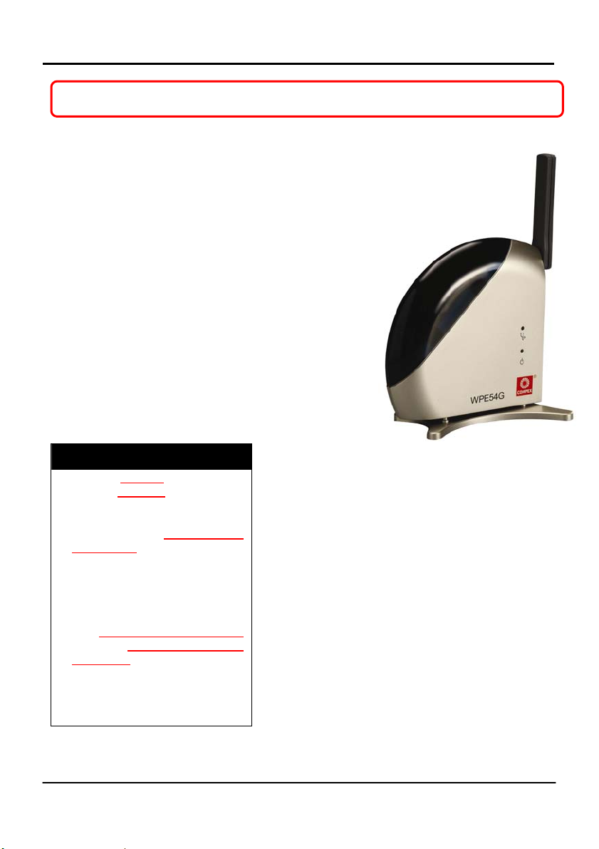
Schematic Overview of the NetPassage WPE54G
The following diagrams provide a schematic overview of the WPE54G.
Side View
WLAN Link/Act LED
Steady GREEN ->
at least one wireless
client present
Flashing GREEN ->
activity is detected in the
network.
LAN Link/ Act LED
YELLOW -> 10Mbps
GREEN -> 100Mb
s
External
Antenna
Rotata
ble antenna
Diagnostic
LED
Steady
GREEN ->
Booting
LED Off ->
Connected
Power LED
Steady
BLUE -> Power
ON
5
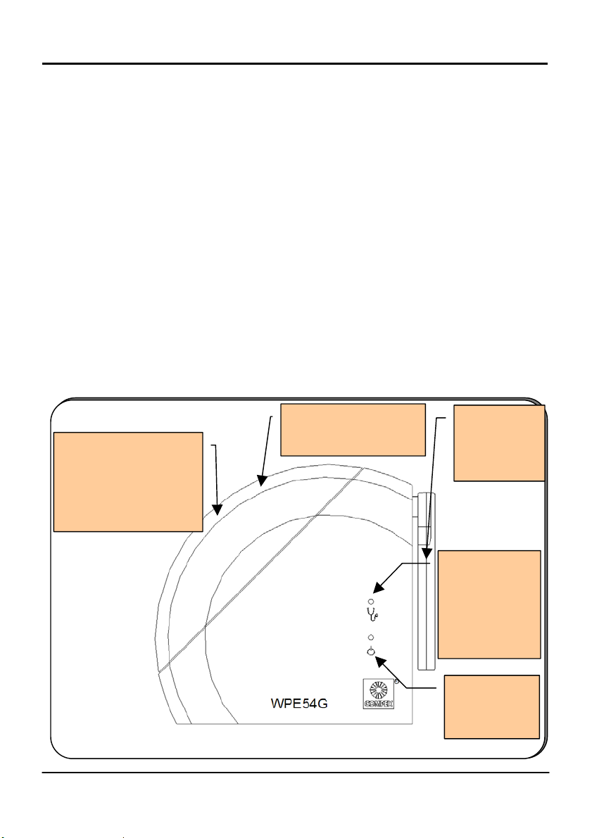
Page 12
Chapter 2
Back View
LAN RJ45
Port
Reset button
Power Input
3.3V, 3A DC
Getting to know your product
External Antenna
When to use which mode
The WPE54G is unique in the sense that it may operate in up to 5 different complex
modes in order to best suit any type of network applications that you might require.
We will henceforth employ the generic term AP mode when referring to the Access
Point and Gateway modes and the generic term wireless client mode to refer to the
Access Point Client, the Wireless Routing Client and the Wireless Ethernet Adapter
modes.
This section presents a brief ou tline of the different network applications that can be
accommodated through the different modes of the WPE54G.
The Access Point Mode
This is the default mode of the NetPassage WPE54G. The Access Point mode enables
you to bridge the wireless clients in your network to the wired network infrastructure.
The diagram below illustrates the WPE54G bridging a Fast Ethernet network with
Wireless 802.11b and 802.11g networks.
6
Page 13

Chapter 2
(
Notebooks with
WL54G cards
Wireless-G clients)
PC with WLU11A
USB adapter
(Wireless-B client)
Compex
NetPassage
WPE54G
The Access Point Client Mode
Getting to know your product
Server PC
Switch
Workgroup
PCs connected
to switch/hub
W
hen configured in the AP Client
mode, the WPE54G acts as a
wireless client which can operate
concurrently with another access
point to perform transparent
bridging between two Fast Ethernet
networks.
In this diagram, the top local bridge
device is just a normal access point
which also supports wireless clients.
The bottom remote end uses an
AP/bridge which is set to AP client
mode and does not support wireless
clients
.
7
Page 14

Chapter 2
Getting to kno w your prod uct
The Gateway Mode
Or more simply put: Broadband Internet sharing in a wireless network!
Since the WPE54G supports different types of broadband connections, the first step
towards a successful setup of the WPE54G as a Broadband Internet Gateway is to
identify the type of broadband Internet access you are subscribed to.
Static IP address
Use this type of connection if you have subscribed to a fixed IP address or a range of
fixed IP addresses from your Internet Service Provider.
Dynamic IP address
When powered through this type of connection, the WPE54G will request for an IP
address which will be automatically assigned to it by your Internet Service Provider.
For instance, this type of connection applies for:
- Singapore Cable Vision subscribers
- @HOME Cable Service users
Certain Internet Service Providers request for a DHCP Client ID before allocating an
IP address. In such a case, you should configure the System Identity with the DHCP
Client ID.
PPP over Ethernet (PPPoE)
Select this type of connection if you are using ADSL services in a country utilising
standard PPP over Ethernet for authentication.
For instance:
- if you are in Germany which uses T-1 connection or
- if you are using SingNet Broadband or Pacific Internet Broadband in
Singapore.
Singapore ADSL (Ethernet 512K)
All other ADSL subscribers in Singapore including SingTel Magix SuperSurf users
should opt for this type of connection.
8
Page 15

Chapter 2
Getting to kno w your prod uct
Australia BPA Cable
This type of connection is especially customised for Big Pond Cable Internet users in
Australia.
PPTP
The Point-to-Point Tunneling Protocol (PPTP) mode enables the implementation of
secure multi-protocol Virtual Private Networks (VPNs) through public networks.
The Wireless Routing Client Mode
When set up in the Wireless Routing Client mode, the WPE54G connects your
network on client site to any Internet connection while ensuring communication
among the clients on your network as well. The Routing Client would thus act as a
secure Internet gateway on your LAN, not only protecting the LAN against outside
intruders but also filtering internal users’ access to the Internet, if so configured.
An application of this mode could be for the WPE54G to act as a wireless client
bridge for broadband routing. In such a case, the Ethernet port of the wireless routing
client would be used for ad hoc connection with other devices on the network while
access to the Internet would be achieved through wireless communication with
another access point, which connects to the Internet via an ADSL/Cable modem.
The Wireless Ethernet Adapter Mode
This mode is intended for usage by Internet Service Providers. It is conceptually close
to the Access Point Client mode in that the W PE54G used in this mode, is able to
communicate wirelessly with another access point to perform transparent bridging
between two networks.
The difference lies in that the function of a network adapter is to interface a computer
to a network. Thus, the Wireless Ethernet Adapter connects with a single wired
workstation only. This characteristic implies more leeway for the user to set up more
explicit parameters for better control over communication to and from the workstation.
9
Page 16

Chapter 3
s
A
,
Hardware Installation
Chapter 3: Hardware Installation
NetPassage WPE54G Hardware Setup
In two simple steps, you may power ON and begin configuring the WPE54G device.
Hardware Setup
1
To configure the device,
connect the Ethernet cable
from a PC on one end, and
then connect the cable to the
ocket labeled LAN on the
NetPassage WPE54G.
2
ttach the power adapter to
the main electrical supply
connect the power plug onto
the socket labeled DC3.3V3A
on the NetPassage WPE54G.
You may turn the device ON.
and
10
Page 17

Chapter 4
Web-based configuration interface
Chapter 4: Web-based configuration interface
Log-in to web-based configuration interface
Once you have verified that the WPE54G is switched on and that your PC is
connected to the WPE54G’s LAN port, you can set up the WPE54G to meet your
network requirements through the web-based configuration interface.
There are 2 alternative ways of accessing the web-based configuration interface:
1. Through the uConfig utility
Compex has developed uConfig to give the user direct access to webconfigurable Ethernet devices.
Accessing the Web-based Configuration Interface
(a). Through the uConfig utility:
Insert the Product CD into the
1
CD-ROM drive.
It will automatically run to the
page shown below.
2
1. Click on Utilities.
2. Click on the uConfig program
to run it.
You will see the screen shown in
step 3.
11
Page 18

Chapter 4
r
x
1. Ensure that the entry for the
3
NetPassage WPE54G is
selected under the Compe
Products List.
2. Click on
This opens the WPE54G’s
configuration screen shown in
the next step.
NOTE: The uConfig feature appears on all Compex devices
!
Open Web.
4
The password is set to password by
default.
Press the
the set up pages.
Web-based configuration interface
Log On! button to ente
offering web-based configuration.
2. Through your web browser
Accessing the Web-based Configuration Interface
(b). Through your Web browser:
1. Open your web browser.
2. At the Address bar, enter the
default IP address of the WPE54G,
which is
3. Press
This opens the WPE54G’s
configuration screen shown on the
right.
4. Press the
the set up pages.
http://192.168.168.1
Enter.
Log On! button to enter
12
Page 19

Chapter 5
r
Basic configuration
Chapter 5: Basic configuration
Basic configuration
The default mode set by the WPE54G is the Access Point mode.
From the Configuration menu, the few steps illustrated below will enable you to
change to your required mode of operation.
Basic Configuration
The screen illustrated on the
1
right is the default web page
of the WPE54G.
Click on
from the Configuration
menu as shown below right to
set the WPE54G to you
required mode.
Mode Selection
2
1. Select your required mode
from the Network Mode
drop-down list.
2. Click on the
Setup Details
to access the setup page
for your selected mode.
Wireless
button
We illustrated with the
Wireless Routing Client
mode as shown below left.
13
Page 20

Chapter 5
t
k
t
3
You can overwrite the default
parameters set by Compex to
enter the parameters for your own
network.
1. The Access Point Name
field appears when the
WPE54G is in AP mode
and refers to the identity
of the device. Each name
can reach a maximum of
31 alphanumeric
characters.
When the WPE54G is
operated in wireless clien
mode, this field is referred
to as Station Name
instead.
It is a good practice to
name the access points
uniquely, particularly
when there are several
devices in the network.
2. In AP mode, the ESSID
represents a unique
identifier for the networ
group. It is a case-sensitive
string consisting of a
maximum of 32
characters.
When the WPE54G is
operated in wireless clien
mode, this field is referred
to as SSID instead.
All devices connecting to
a specific network should
have the same ESSID
value.
Basic configuration
14
Page 21

Chapter 5
k
r
3. The Wireless Mode drop-down list
provides a selection of networ
environment types in which to
operate the WPE54G:
- 802.11b only;
- 802.11b/g mixed, which stands
for both b and g environments;
- 802.11b/g mixed long, used
when long preamble is
configured;
- 802.11g only;
- 802.11 test, which supports data
transmission rates of 1, 2, 5.5 and
11 Mbps;
- B-WIFI, which is useful when WIFI compatibility is required.
4. Whenever the WPE54G is operated
in wireless client mode, a PS Mode
option appears.
PS mode stands for Power Saving
mode and if enabled, allows
more efficient power usage.
5. The Channel drop-down list
indicates which active channel is
being used for data transmission.
Different countries have different
number of channels available fo
transmission.
6. The RTS Threshold value determines
the minimum size of a packet in bytes
that would trigger the RTS
mechanism.
The value extends from 0 to 3000
bytes, where a value of 0
indicates that all the packets
would be transmitted using RTS.
We illustrate with 2432.
Basic Configuration
15
Page 22

Chapter 5
g
w
r
7. The Frag Threshold value
indicates the maximum size
that a packet can reach
without being fragme nted. The
value ranges from 256 to 2346
bytes. We illustrate with 2346.
8. A Frame Burst Size value is
required when using Nitro
technology to help improve
network performance. A
suggested value is 1500.
For Access Point and Gateway modes
only:
9. When running in Closed
System, the WPE54G will not
broadcast its SSID. This
enhanced security mode
requires any wireless user to
enter the WPE54G’s SSID
before being able to gain
access to it.
10. The Transmit Power drop-down
lists a ran
e of transmission
Basic Configuration
4
You can exit the configuration
interface by clicking on
ExituConfig.
Otherwise, to change the
WPE54G to a different mode:
Repeat Steps 1 & 2.
You will have to wait a fe
seconds for the system’s
automatic reboot before
being able to log in again fo
configuration.
NOTE: The values illustrated in the above examples are suggested
!
values for their respective parameters.
16
Page 23

Chapter 5
Basic Configuration
Show Link Information – a helpful feature
The Show Link Information function offers a summary of the link data when the
WPE54G is in either of the Access Point Client, Wireless Routing Client or the
Wireless Ethernet Adapter mode.
Show Link Information
Access Point Client/Wireless Routing Client/Wireless Ethernet Adapter:
Click on the Show Link
1
Information
shown on the right.
button as
2
When an AP is connected to a
wired network and a set of
wireless stations, it is referred to as
a Basic Service Set (BSS).
The Link Information table
illustrates the following data:
1. The State refers to the MAC
address of the BSS.
2. The Current Channel is the
channel being presently
used for transmission.
3. The Current TxRate refers to
the rate of data transmission
and is measured in Mbps.
4. The Signal Strength, given in
percentage form, shows the
intensity of the signal
received and hence the
connection strength.
17
Page 24

Chapter 5
t
r
Using the SYSTEM TOOLS Menu
Using the SYSTEM TOOLS Menu
System Identity
If your network operates with several Compex NetPassage WPE54G, you would find
it useful to have a means of identifying each individual device.
In certain cases, your Internet Service Provider might request for a System Name
before allowing you to access the Internet. This System Name also serves as a DHCP
Client ID during negotiations with the DHCP Server for dynamic IP address
allocation.
You can define the System Identity of the WPE54G to be also utilised as System
Name or as DHCP Client ID.
Follow the next few steps to define a System Identity for your WPE54G.
Using the SYSTEM TOOLS Menu
System Identity:
Click on System Identity
1
from the System Tools menu.
Apply button to
18
2
1. Enter the DHCP Client ID
assigned by your ISP in the
System Name field.
2. Fill in the name of a person to
contact in the System Contac
field.
3. Fill up the System Location field. If
there are multiple devices in you
network or building, this entry
might help to identify the device.
4. Click on the
effect the changes.
Page 25

Chapter 5
r
k
Using the SYSTEM TOOLS Menu
Set System’s Clock
Synchronising the built-in clock of the WPE54G with the time kept by your
workstation will enable you to effectively manage and operate the time-based
functions provided by the WPE54G.
Follow these steps to set your system’s clock.
Using the SYSTEM TOOLS Menu
Set System’s Clock:
Click on Set System’s
1
Clock
menu.
from the System Tools
Apply button
2
1. Select the appropriate time
zone from the Select to
Change the Time Zone fo
the system Location drop-
down list.
2. Enable the Auto Time Setting
(SNTP) radio button.
SNTP stands for Simple Networ
Time Protocol and is used to
synchronise computer clocks in
the Internet.
3. Fill in the Time Servers field.
4. Click on the
to effect the changes.
19
Page 26

Chapter 5
Using the SYSTEM TOOLS Menu
Firmware Upgrade
Compex products are designed for upgradeability. You can check the current version
of your firmware by clicking on About System from the HELP menu.
Keep your WPE54G updated with the latest capabilities by downloading its latest
firmware revision from either of Compex’s corporate web sites at
www.compex.com.sg or www.cpx.com and by following the next steps.
Using the SYSTEM TOOLS Menu
Firmware Upgrade:
Click on Firmware Upgrade
1
from the System Tools menu.
To begin with, ensure tha t you ha v e
downloaded the latest firmware
2
onto your local hard disk drive.
1. Key in the path and file name of
the downloaded file in the
Upgrade Firmware (path and file
name) field.
Alternatively, click on the
button to locate the file.
2. Click on the
3. Follow the instructions given during
the upgrading process.
When the process is complete, the
WPE54G will automatically restart.
Upgrade button.
NOTE: The firmware upgrade process must NOT be interrupted
!
otherwise the device might become unusable.
Browse
20
Page 27

Chapter 5
Using the SYSTEM TOOLS Menu
Save or Reset Settings
This feature enables you to save the configuration settings with which you have
customised your WPE54G. You may choose to save the configuration profile, to make
a backup of it onto your hard disk, to restore an earlier profile saved on file or to reset
the WPE54G back to its default settings.
The following steps illustrate how to use this feature
.
Using the SYSTEM TOOLS Menu
Save or Reset Settings:
Click on Save or Reset
1
Settings
Tools menu.
from the System
If you want to save the current
2
settings with which you have
configured the WPE54G:
1. Click on the
Save button.
2. Restart the WPE54G to
ensure that it is using the
right profile.
If you want to back up the
WPE54G’s current settings onto
your hard disk drive:
Click on the
Backup
button.
21
Page 28

Chapter 5
Using the SYSTEM TOOLS Menu
If you want to retur n the WPE54G
to an earlier configuration from a
backup file:
1. Click on the
button to searc h for the
backup file.
Or you may type in the
path name of the fil e in
Browse
the Restore the
Machine’s configuration
(path and file name)
field as illustrated left.
2. Click on the
If you want to discard
configuration you have made
button.
Restore
ALL the
and thus restore the WPE54G to its
initial factory settings:
Click on the
Reset
button.
Clear and
22
Page 29

Chapter 5
Using the SYSTEM TOOLS Menu
Reboot System
Most of the changes you make to the system’s settings require a reboot of the
WPE54G before the new configuration can take effect.
The following steps will guide you through the rebooting process
.
Using the SYSTEM TOOLS Menu
Reboot System:
Click on Reboot System
1
from the System Tools menu.
2
confirm whether to execute a
You will be prompted to
system reboot.
Click on the
whenever you are ready to
restart.
Yes button
23
Page 30

Chapter 5
Using the SYSTEM TOOLS Menu
Change Password
It is recommended that you change the password of the WPE54G, which is case
sensitive and is set by default, to password. This system password is required for
accessing the web-based configuration interface as well as in Telnet sessions.
You can change the system password by following the next few steps.
Using the SYSTEM TOOLS Menu
Change Password:
Click on Change Password
1
from the System Tools menu.
1. Key in the current
2
password. The factory
default is password.
2. Enter the new password in
the New Password field as
well as in the Confirm
Password field.
3. Click on the Apply
button.
24
Page 31

Chapter 5
Using the SYSTEM TOOLS Menu
Logout
To exit the web-based configuration environment, follow the next few steps.
Using the SYSTEM TOOLS Menu
Logout:
Click on Logout from the
1
System Tools menu.
2
The system will take you to a Login
prompt as shown in the figure on
the left.
If you need to access the
WPE54G’s configuration interface
again:
Click on the Logon
button.
25
Page 32

Chapter 5
r
Using the HELP Menu
Using the HELP menu
Get Technical Support
This page presents the contact information of Compex’s technical support centres
around the world.
To access this page
Using the HELP Menu
Get Technical Support:
Click on Get Technical
1
Support
menu.
:
from the HELP
The WPE54G is a feature-packed
2
device. If you require furthe
information than provided in the
manual or data sheet, please
contact one of Compex’s
Technical Support Centres by
mail, email, fax or telephone.
26
Page 33

Chapter 5
Using the HELP Menu
About System
The About System page displays a summary of your system configuration
information. Support technicians might require specific information about your system
data when they are troubleshooting your configuration. You can use the information
displayed in this page to quickly find the data they need to resolve your system
problem.
Follow the next steps to have a glance at the settings applied in your network
.
Using the HELP Menu
About System:
Click on About System
1
from the HELP menu.
2
The System Information page will
supply information concerning
WPE54G’s configuration settings.
27
Page 34

Chapter 6
(
g)
Advanced Configuration
Chapter 6: Advanced Configuration
Management Port Setup
This section addresses the Advanced DHCP Server Options made available to the
network administrator.
The built-in DHCP server in the WPE54G facilitates the IP address allocation
management of your network by automatically and dynamically allocating addresses
to the devices connected to the network.
However, you may in addition, require DHCP server reservations for specific IP and
MAC addresses. For instance, if you set up a publicly accessible FTP/HTTP server
that resides within a private LAN, while that server would require a fixed IP address,
you would still want the DHCP server to dynamically allocate IP addresses to the rest
of the PCs on the private LAN.
The ability to make IP reservations enables you to assign a fixed IP address to your
FTP/HTTP server and subsequently inform the DHCP server to exclude that specific
address from the pool of addresses it draws on for its dynamic address allocation.
The next diagram illustrates fixed and dynamic IP addressing using the WPE54G.
Fixed & Dynamic IP addressing: DHCP Server Reservations
Wireless-G
clients using
Dynamic IP
addressing
NetPassage
WPE54G
with builtin DHCP
server
Workgroup
Dynamic IP
addressin
Public
FTP/HTTP
Server with fixed
IP (IP address
reserved in
DHCP server)
Switch
28
Page 35

Chapter 6
!
Advanced DHCP Server Options
For more information on DHCP, you can refer to the DHCP Technology Primer
section on the Product CD.
Learn more from our DHCP
Technology Primer
Configuring Advanced DHCP Server Options
Go through the following steps to configure the Advanced DHCP Server Options of
the WPE54G.
Management Port Setup
Advanced DHCP Server Options:
1. Click on Management
1
You will find the Advanced DHCP
Server Options near the bottom of
the page.
This will bring up the screen
displayed below in Step 2.
Port
from the
Configuration menu.
2. Click on
DHCP Leases
information of the current
IP leases managed by the
DHCP server as in the figure
below right.
3. Click on
Reservations
any specific IP Address for
a specific network MAC
address.
Show Active
to view
DHCP Server
to reserve
e
X
pert
e
X
pert
29
Page 36

Chapter 6
3
1. The IP address and
Hardware address you
have keyed in will be
added to the table as
shown on the right.
2. Repeat Step 2 if you want
to add more reservations.
2
Advanced DHCP Server Options
1. Enter the host IP that you wish
to reserve in the IP address
field.
2. Fill in the Host Name field.
3. Key in the MAC address of the
PC’s Ethernet card in the
Hardware Address field.
4. Click on the
Add button to add
this entry to the DHCP Server
Reservations.
30
Page 37
Chapter 6
SNMP Setup
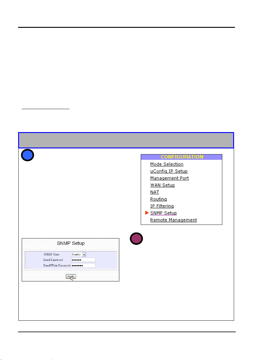
SNMP Setup
Simple Network Management Protocol (SNMP) is a set of communication protocols
that separates the management architecture from the architecture of the hardware
devices. Since it is an extensible but yet simple solution, requiring little code to be
implemented, SNMP has quickly become a de facto standard for network
management.
Enabling SNMP
The following will guide you in enabling SNMP in the WPE54G.
SNMP Setup
Enabling SNMP:
1
Click on
Configuration menu.
The screen shown below will appear.
SNMP Setup from the
2
1. Select
The default Read Password is set to
public while the default Read/Write
Password is private.
2. Click on the
SNMP Parameters accepted will
appear in the Message Window.
Enable from the SNMP
State drop-down list.
Apply button.
31
Page 38

Chapter 6
WEP Encryption
WEP Encryption
Wired Equivalent Privacy (WEP) is a security protocol for wireless local area
networks (WLANs). It aims to provide security by encrypting data over radio waves
so that it is protected while being transmitted from one end point to another.
Both the access point and the client device use the same WEP key to encrypt and
decrypt messages. WEP keys encrypt both unicast and multicast messages within the
network.
The WPE54G supports both 64-bit as well as 128-bit WEP encryption keys in both
alphanumeric as well as hexadecimal format.
Configuring WEP Encryption
Follow the next steps to enable the WEP encryption feature in your WPE54G.
Configuring WEP Encryption
1. Click on the WEP Encryption
1
button.
On the WEP Setup page which
appears as shown below right:
2. Select your required level of
WEP encryption from the dropdown list as shown in the figure
on the right.
WEP Encryption is disabled by
default.
3. Click on the
Apply button.
e
X
pert
e
X
pert
32
Page 39

Chapter 6
y
y
t
1. Select the key which you
3
want to use for data
encryption from the Encryp
data with drop-down list.
2. Click on the
button.
WEP key applied will
appear in the Message
Window.
Apply
WEP Encryption
For 64-bit WEP Encryption:
2
If you are using
alphanumeric notation:
Enter 5 alphanumeric
characters into each
Key field.
If you are using
hexadecimal notation:
Enter 5 pairs of
hexadecimal values
into each of the Ke
fields.
For 128-bit WEP Encryption:
If you are using
alphanumeric notation:
Enter 13 alphanumeric
characters into each
Key field.
If you are using
hexadecimal notation:
Enter 13 pairs of
hexadecimal values
into each of the Ke
fields.
33
Page 40

Chapter 6
r
IEEE 802.1X/RADIUS Setup
IEEE 802.1X/RADIUS Setup
The use of IEEE 802.1X offers an effective framework for authenticating and
controlling user traffic to a protected network, as well as for dynamically varying
encryption keys. This feature is only accessible when the WPE54G is configured in
the Access Point mode.
These steps act as a guide in the IEEE 802.1X/RADIUS setup.
The IEEE 802.1X/RADIUS Setup
e
X
pert
e
The Access Point mode:
Click on IEEE
1
802.1X/RADIUS
Configuration menu.
The screen shown on the right
will appear.
from the
X
pert
You can overwrite the default
2
parameters set by Compex to
enter the parameters for you
network.
1. If MAC Authentication is
enabled, the client’s MAC
address will have to be
authenticated before it can
access network resource.
34
Page 41

Chapter 6
x
r
IEEE 802.1X/RADIUS Setup
2. The 802.1X Security Mode offers 3
options:
(a). None
The 802.1x security mode is disabled
and only WEP encryption is used.
(b). 802.1X
The 802.1x security mode is enabled.
WEP keys are not required since this
mode creates keys dynamically.
(c). Mixed Mode
This mode combines the 802.1
mode with WEP. You will have to
provide WEP key from WEP tab entry
and can only use key index 0.
3. The Primary/Secondary RADIUS Server
IP addresses will be used fo
authentication.
4. The Authentication Port has to match
the port number that the RADIUS server is
using. It is set to 1812 by default
5. The RADIUS Shared Secret Key serves to
validate RADIUS communication
between clients and servers. The key has
to be the same for the user and the
RADIUS server. You can choose any
alphanumeric string as shared secret. The
key is case-sensitive and set to private by
default.
35
Page 42

Chapter 6
IEEE 802.1X/RADIUS Setup
6. The Broadcast Key Rotation refers to the
length of tim e in sec onds be fore the network
broadcast WEP key is changed.
7. The Maximum Retransmission is the
maximum number of times an authentication
value may be allowed to retransmit before
authentication fails.
8. When in the 802.1X or in the Mixed mode,
you can select the k ey len gth to be eith er 64
bits or 128 bits long, from the Transient Key
Length drop-down list.
9. By default, EAP-MD5 authentication is
disabled. If you enable this feature, you will
have to key in a static WEP key since EAP-
MD5 authentication does not generate
dynamic WEP keys.
36
Page 43

Chapter 6
WAN Setup
WAN Setup
The WAN setup is only operational when the WPE54G is configured in either the
Gateway mode or the Wireless Routing Client mode.
If your ISP requires your Ethernet MAC address to be authenticated before assigning
an IP address to the WAN interface, the MAC address of the Ethernet adapter
originally installed on your PC with the cable modem will need to be cloned to the
WPE54G. That PC must be used to log on to the WPE54G to change its Ethernet
MAC address to that of the Ethernet card.
The following steps will act as guideline for your WAN setup.
WAN Setup
Gateway/Wireless Routing Client mode:
Click on WAN Setup from the
1
Configuration menu.
The WAN Setup screen on the
right will appear.
e
X
pert
eXpert
37
Page 44

Chapter 6
3
Enable the radio button
corresponding to your Internet
connection type.
If you are using Static IP
Address allocation:
1. Replace the current IP
Address and Gateway IP
Address fields with the
relevant IP addresses
given by your ISP.
2. Click on the
3. Click on the
button to restart the
system and enable the
changes to take effect.
Save button.
Reboot
WAN Setup
The WPE54G is set to Dynamic IP
2
address allocation by default.
If you need to change the type of
Internet connection at any time
during setup:
Click on the
Change button.
The Select WAN Type screen shown
below left will appear.
If you need to tes t the connection
with your user profile at any time
during setup:
Click on the
Connect button
present in all the setup pages
to manually activate the
session.
38
Page 45

Chapter 6
If you are changing to PPP over
Ethernet mode:
1. You can specify a different MTU than
the default 1462.
2. Key in the account name assigned by
your ISP in the Username field.
3. Follow with your ISP account
Password.
4. If you want th e WPE54G to maintai n
an established connection with the ISP:
Select the Always-On radio
button.
Then, if you want to change the
maximum time the WPE54G
should wait before attempting to
connect to your ISP:
Fill in the Reconnect Time
Factor field set to 30 seconds
by default.
Otherwise, the On-Demand mode is set
by default so that the WPE54G
connects to the ISP automatically only
upon receiving Internet requests from
your clients.
The Idle Timeout feature
associated with the On-demand
option allows you to specify the
time span in seconds after which
your WPE54G should
automatically disconnect if there
is no Internet ac tivity.
Key in ‘0’ if you want to disable
the idle timeout.
5. Click on the
Save button.
6. Click on the
Reboot button to restart
the system and enable the changes to
take effect.
WAN Setup
39
Page 46
Chapter 6
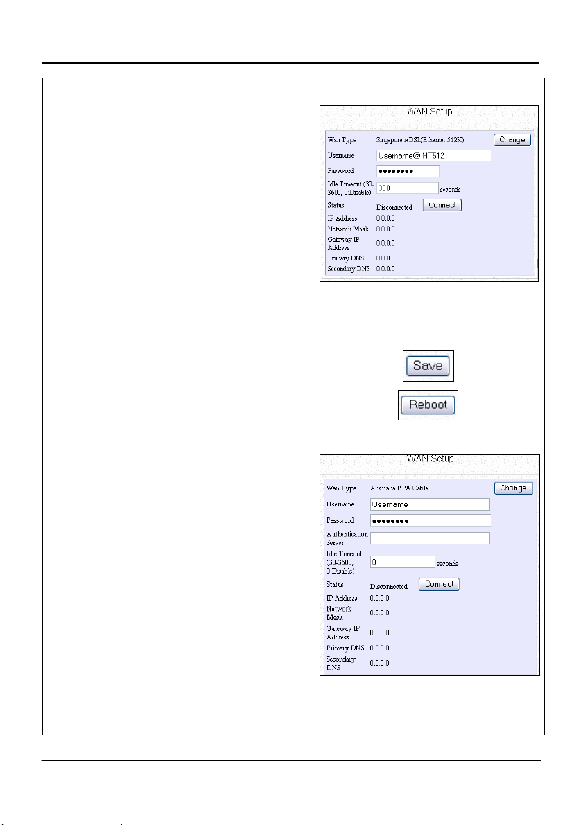
r
If you are changing to Singapore ADSL
(Ethernet 512K) mode:
1. Key in the account name assigned by
your ISP in the Username field.
2. Follow with your ISP account
Password.
3. The Idle Timeout feature allows you to
specify the time span in seconds during
which your WPE54G should remain
disconnected from th e ISP after the last
Internet activity.
Key in ‘0’ if you want to disable
the idle timeout.
Else, type in a value ranging
from 30 to 3600 seconds.
4. Click on the
5. Click on the
the system and enable the changes to
take effect.
If you are switching to Australia BPA
Cable connection:
1. Key in the account name assigned by
your ISP in the Username field.
2. Follow with your ISP account
Password.
3. Fill in the Authentication Server field as
indicated by your ISP.
4. The Idle Timeout feature associated
with the On-demand option allows you
to specify the time span in seconds afte
which your WPE54G should
automatically disconnect if there is no
Internet activity.
Save button.
Reboot button to restart
WAN Setup
40
Page 47

Chapter 6
k
4. Click on the
5. Click on the
the system and enable the changes to
take effect.
Key in ‘0’ if you want to disable
the idle timeout.
Else, type in a value ranging
from 30 to 3600 seconds.
Save button.
Reboot button to restart
If you are using PPTP connection:
1. You can modify the Client IP and the
Netmask according to your networ
parameters.
2. Key in the account name assigned by
your ISP in the Username field.
3. Follow with your ISP account
Password.
4. Fill in the appropriate VPN server’s IP
address in the VPN Server field.
5. The Idle Timeout feature allows you to
specify the time span in seconds during
which your WPE54G should remain
disconnected from th e ISP after the last
Internet activity.
Key in ‘0’ if you want to disable
the idle timeout.
Else, type in a value ranging
from 30 to 3600 seconds.
6. Click on the
7. Click on the
the system and enable the changes to
take effect.
Save button.
Reboot button to restart
WAN Setup
41
Page 48

Chapter 6
WAN Setup
4
To clone the MAC address of the
PC onto the router:
Click on the Clone Mac button.
You will be asked to reboot the
system for the change to take
effect.
5
To revert to the original MAC
address of the router:
Click on the Restore Mac button.
You will be asked to reboot the
system for the change to take
effect.
Wireless Setup - The Wireless Distributed System (WDS)
The Wireless Distribution System (WDS) feature allows you to indefinitely extend the
range of your network infrastructure by simply connecting access points wirelessly.
The inherent flexibility of the WDS allows the setup of numerous advanced
configurations for your network infrastructure -- each having specific operational
benefits. We shall list two popular WDS network configurations which can be set up
using the WPE54G:
Star Configuration Infrastructure Network
In a star configuration WDS, links are established between one root (central)
WPE54G which acts as an access point and several other (satellite) WPE54G’s. The
satellite WPE54G’s are positioned to cover an area beyond that covered by the single
root device.
42
Page 49

Chapter 6
g
WDS Setup
In addition to the extended coverage area, since the WPE54G is an advanced router
switching device, each WPE54G can service its own wired and wireless infrastructure
network.
WDS: Star
Confi
uration
Satellite WPE54G
Satellite WPE54G
INTERNET
Cable/ADSL
modem
Root WPE54G
Satellite WPE54G
In this setup, the root access point has three WDS ports enabled for three different
links while each of the three satellite access points has only one WDS port enabled.
Chain Configuration Infrastructure Network
A chain configuration WDS spans an area in length, for instance a long corridor. The
satellite access points are chained together starting from a root access point as
illustrated below:
WDS: Chain
Configuration
Cable/ADSL
INTERNET
modem
Root WPE54G
Satellite WPE54G
Satellite WPE54G
Satellite WPE54G
43
Page 50

Chapter 6
WDS Setup
In this setup, the WPE54G at either end of th e chain will h ave on e WD S port enab led,
while the access points in the middle will have two WDS ports configured to associate
with the neighbouring WPE54G upward and downward in the chain.
The following steps will guide you in setting up WDS in your WPE54G.
WDS Configuration Setup
1
Click on the WDS
Configuration
button.
As illustrated on the WDS
2
Setup page above left, the
WDS feature is Disabled by
default.
1. Select Enable from the
WDS Global Control
drop-down list to
operate WDS.
2. Click on the
button.
The WDS Status page
displayed below left will
appear.
e
e
X
X
pert
pert
Apply
44
 Loading...