

Page 1

StorageWorks by Compaq
g
Modular SAN Array Fabric Switch 6
User Guide
Part Number 230934-002
June 2002 (Second Edition)
This guide is designed to be used as step-by-step instructions for
installation and as a reference for operation, troubleshootin
upgrades.
, and future
Page 2

© 2002 Compaq Information Technologies Group, L.P.
Compaq, the Compaq logo, and StorageWorks are trademarks of Compaq Information
Technologies Group, L.P. in the U.S. and/or other countries.
Microsoft, MS-DOS, Windows, and Windows NT are trademarks of Microsoft Corporation in
the U.S. and/or other countries.
Compaq shall not be liable for technical or editorial errors or omissions contained herein. The
information in this document is provided “as is” without warranty of any kind and is subject to
change without notice. The warranties for Compaq products are set forth in the express limited
warranty statements accompanying such products. Nothing herein should be construed as
constituting an additional warranty.
Modular SAN Array Fabric Switch 6 User Guide
June 2002 (Second Edition)
Part Number 230934-002
Page 3

Contents
About This Guide
Intended Audience............................................................................................................ vii
Important Safety Information ...........................................................................................vii
Symbols on Equipment..................................................................................................... vii
Rack Stability..................................................................................................................... ix
Symbols in Text.................................................................................................................ix
Text Conventions................................................................................................................x
Related Documents............................................................................................................. x
Getting Help........................................................................................................................ x
Compaq Technical Support......................................................................................... xi
Compaq Website ......................................................................................................... xi
Compaq Authorized Reseller ...................................................................................... xi
Chapter 1
Overview of the Switch
The MSA Fabric Switch 6 ...............................................................................................1-2
Features............................................................................................................................ 1-3
Rear View of the Modular San Array 1000..................................................................... 1-4
Installation .......................................................................................................................1-5
Ethernet RJ-45 Cable ................................................................................................ 1-5
DB-9 Serial Cable ..................................................................................................... 1-5
Hot-Pluggable ...........................................................................................................1-6
Modular SAN Array Fabric Switch 6 User Guide iii
Page 4

Contents
Chapter 2
Initial Configuration of the Switch
Configuration Overview.................................................................................................. 2-2
Using the Text-based UI to Configure the Switch .......................................................... 2-3
Connecting a Terminal to the Switch ....................................................................... 2-3
Logging in to the Text-based UI............................................................................... 2-5
Accessing Networking Parameters ........................................................................... 2-6
Accessing Management Parameters ....................................................................... 2-10
Accessing the CLI................................................................................................... 2-11
Exiting the Text-based UI....................................................................................... 2-11
Resetting the Switch ............................................................................................... 2-11
Using the Array Configuration Utility-XE (ACU-XE) to Configure the Switch.......... 2-12
Accessing the Switch Configuration Option of the ACU-XE ................................ 2-13
Initial Switch Configuration ................................................................................... 2-16
Advanced Switch Configuration............................................................................. 2-18
Chapter 3
MSA Fabric Switch 6 Management Utility
Defining System Requirements....................................................................................... 3-2
Launching the Management Utility................................................................................. 3-3
Describing the Console ................................................................................................... 3-4
Task Selection Toolbar............................................................................................. 3-5
Status Panel............................................................................................................... 3-5
Main Management Panel.......................................................................................... 3-8
Using MSA Fabric Switch 6 Management Utility........................................................ 3-15
Managing and Monitoring Individual Ports............................................................ 3-15
Managing from the System Information Panel....................................................... 3-31
Monitoring from the Device View ......................................................................... 3-48
Session Configuration............................................................................................. 3-49
Setting up Zoning ................................................................................................... 3-50
iv Modular SAN Array Fabric Switch 6 User Guide
Page 5

Chapter 4
Troubleshooting
Troubleshooting Guidelines.............................................................................................4-1
Troubleshooting the MSA Fabric Switch 6 .....................................................................4-2
Reading the Global Status Indicator..........................................................................4-2
Reading the Ethernet Indicators ................................................................................4-4
Reading the Port Indicators....................................................................................... 4-6
Serial Communication Problems............................................................................... 4-6
Connections .....................................................................................................................4-6
Compaq-supported Small Form Factor Pluggables (SFP) ........................................4-7
Fibre Channel Cables ................................................................................................4-7
Temperature Control........................................................................................................4-8
Preventative Maintenance Solutions................................................................................4-8
Appendix A
Regulatory Compliance Notices
Federal Communications Commission Notice ............................................................... A-1
Federal Communications Commission Notice ............................................................... A-2
Modifications ........................................................................................................... A-2
Cables....................................................................................................................... A-2
Canadian Notice (Avis Canadien) .................................................................................. A-2
European Union Notice .................................................................................................. A-3
Contents
Appendix B
Electrostatic Discharge
Grounding Methods........................................................................................................ B-2
Modular SAN Array Fabric Switch 6 User Guide v
Page 6

Contents
Appendix C
Command Line Interface
Invoking the Command Line Interface ........................................................................... C-3
Using the Command Line Interface ................................................................................C-4
Logging Out of the CLI............................................................................................ C-5
Exiting from CLI ......................................................................................................C-5
Reset ......................................................................................................................... C-5
Beacon ......................................................................................................................C-5
Setting up Zoning..........................................................................................................C-37
Zoning Elements..................................................................................................... C-37
Naming Rules for Zone Members, Zones, and Zone Sets......................................C-39
Zoning Limitations for Zone Members, Zones, and Zone Sets..............................C-39
Using the CLI to Configure Zoning........................................................................C-40
Appendix D
Laser Precautions and Fibre Cables
Laser Precautions......................................................................................................D-1
Fibre Channel Cable .................................................................................................D-2
Appendix E
Updating the Fabric Switch MSA Fabric Switch 6 Management Utility
Finding the MSA Fabric Switch 6 Management Utility Version Number ...............E-1
Downloading the Switch Management Utility Update............................................. E-1
Updating the Switch using the Web Browser Interface............................................ E-2
Updating the Switch using the Command Line Interface......................................... E-2
Updating the Switch 6 using the Boot Menu............................................................ E-4
Index
vi Modular SAN Array Fabric Switch 6 User Guide
Page 7
This guide is designed to be used as step-by-step instructions for installation and as a
reference for operation, troubleshooting, and future upgrades.
Intended Audience
This guide is intended for readers with a moderate level of SAN and system
administration experience.
Important Safety Information
Before installing this product, read the Important Safety Information document
provided.
About This Guide
Symbols on Equipment
The following symbols may be placed on equipment to indicate the presence of
potentially hazardous conditions:
WARNING: This symbol, in conjunction with any of the following symbols,
indicates the presence of a potential hazard. The potential for injury exists if
warnings are not observed. Consult your documentation for specific details.
Modular SAN Array Fabric Switch 6 User Guide vii
Page 8
About This Guide
Weight in kg
Weight in lb
This symbol indicates the presence of hazardous energy circuits or electric
shock hazards. Refer all servicing to qualified personnel.
WARNING: To reduce the risk of injury from electric shock hazards, do not
open this enclosure. Refer all maintenance, upgrades, and servicing to
qualified personnel.
This symbol indicates the presence of electric shock hazards. The area
contains no user or field serviceable parts. Do not open for any reason.
WARNING: To reduce the risk of injury from electric shock hazards, do not
open this enclosure
This symbol on an RJ-45 receptacle indicates a network interface connection.
WARNING: To reduce the risk of electric shock, fire, or damage to the
equipment, do not plug telephone or telecommunications connectors into this
receptacle.
This symbol indicates the presence of a hot surface or hot component. If this
surface is contacted, the potential for injury exists.
WARNING: To reduce the risk of injury from a hot component, allow the
surface to cool before touching.
These symbols, on power supplies or systems, indicate that the
equipment is supplied by multiple sources of power.
WARNING: To reduce the risk of injury from electric shock,
remove all power cords to completely disconnect power from the
system.
This symbol indicates that the component exceeds the recommended
weight for one individual to handle safely.
WARNING: To reduce the risk of personal injury or damage to the
equipment, observe local occupational health and safety requirements
and guidelines for manual material handling.
viii Modular SAN Array Fabric Switch 6 User Guide
Page 9
Rack Stability
WARNING: To reduce the risk of personal injury or damage to the equipment,
be sure that:
• The leveling jacks are extended to the floor.
• The full weight of the rack rests on the leveling jacks.
• The stabilizing feet are attached to the rack if it is a single-rack installation.
• The racks are coupled in multiple-rack installations.
• Only one component is extended at a time. A rack may become unstable if
more than one component is extended for any reason.
Symbols in Text
These symbols may be found in the text of this guide. They have the following
meanings.
WARNING: Text set off in this manner indicates that failure to follow directions
in the warning could result in bodily harm or loss of life.
About This Guide
CAUTION: Text set off in this manner indicates that failure to follow directions could
result in damage to equipment or loss of information.
IMPORTANT: Text set off in this manner presents clarifying information or specific
instructions.
NOTE: Text set off in this manner presents commentary, sidelights, or interesting points of
information.
Modular SAN Array Fabric Switch 6 User Guide ix
Page 10

About This Guide
Text Conventions
This document uses the following conventions:
• Italic type is used for complete titles of published guides or variables. Variables
include information that varies in system output, in command lines, and in
command parameters in text.
• Bold type is used for emphasis, for onscreen interface components (window
titles, menu names and selections, button and icon names, and so on), and for
keyboard keys.
Monospace typeface is used for command lines, code examples, screen
•
displays, error messages, and user input.
Sans serif typeface is used for uniform resource locators (URLs).
•
Related Documents
For additional information on the topics covered in this guide, refer to the
following documentation:
• StorageWorks by Compaq Modular SAN Array 1000 User Guide, part number
230941
• StorageWorks by Compaq Modular SAN Array 1000 Installation Overview,
part number 230935
Getting Help
If you have a problem and have exhausted the information in this guide, you can get
further information and other help in the following locations.
x Modular SAN Array Fabric Switch 6 User Guide
Page 11

HP Technical Support
In North America, call the HP Technical Support Phone Center at 1-800-652-6727.
This service is available 24 hours a day, 7 days a week. For continuous quality
improvement, calls may be recorded or monitored. Outside North America, call the
nearest HP Technical Support Phone Center. Telephone numbers for worldwide
Technical Support Centers are listed on the HP website,
Be sure to have the following information available before you call HP:
• Technical support registration number (if applicable)
• Product serial number
• Product model name and number
• Applicable error messages
• Add-on boards or hardware
• Third-party hardware or software
• Operating system type and revision level
About This Guide
www.hp.com.
HP Website
The HP website has information on this product as well as the latest drivers and flash
ROM images. You can access the HP website at
www.hp.com.
HP Authorized Reseller
For the name of your nearest HP authorized reseller:
• In the United States, call 1-800-345-1518.
• In Canada, call 1-800-263-5868.
• Elsewhere, see the HP website for locations and telephone numbers.
Modular SAN Array Fabric Switch 6 User Guide xi
Page 12
Overview of the Switch
This guide provides specific information for installing and configuring the
MSA Fabric Switch 6 and its component parts.
Table 1-1: Organization of this Guide
For information about See
Overview of the Switch Chapter 1
Initial Configuration of the Switch Chapter 2
MSA Fabric Switch 6 Management Utility Chapter 3
Troubleshooting Chapter 4
Regulatory Compliance Notices Appendix A
Electrostatic Notices Appendix B
Command Line Interface Appendix C
1
Laser Precautions Appendix D
Updating the MSA Fabric Switch 6 Management
Utility
WARNING: To reduce the risk of personal injury or damage to the equipment,
refer to the user documentation supplied with the server and observe the
appropriate safety precautions.
Modular SAN Array Fabric Switch 6 User Guide 1-1
Appendix E
Page 13
Overview of the Switch
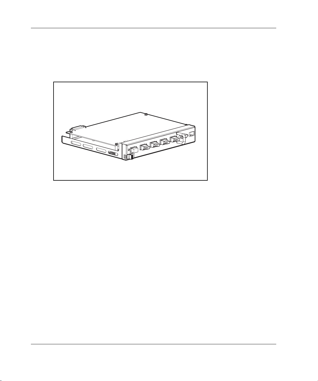
The MSA Fabric Switch 6
The MSA Fabric Switch 6 is an integrated six-port module, featuring a 12 Gbps
switch engine that enables full duplex non-blocking performance on all ports.
Figure 1-1: The MSA Fabric Switch 6
1-2 Modular SAN Array Fabric Switch 6 User Guide
Page 14

Features
The MSA Fabric Switch 6 includes:
• A main board enclosing the 12 Gbps switching engine
• Microprocessor and other hardware logic to support the switch software agents
• MSA Fabric Switch 6 Management Utility
— Full Duplex Communications - A pair of nodes can simultaneously send and
— Automatic Port Bypass - Improves SAN reliability by automatically
• Global Status Indicator (GSI)
• RS-232 serial interface port for configuring the MSA Fabric Switch 6
• 10-base T Ethernet port for communications to host resident management
software applications
• Null modem cable
Overview of the Switch
receive data for an aggregate of 2 Gbps
bypassing errant ports
• Five external 2/1 Gbps ports, 1 internal 2/1 Gbps port
• Auto switch between 1 and 2 Gbps
• Array Configuration Utility-XE (ACU-XE) configuration support
• Compaq Insight Manager (CIM-XE) launch of the Management Utility
Modular SAN Array Fabric Switch 6 User Guide 1-3
Page 15
Overview of the Switch
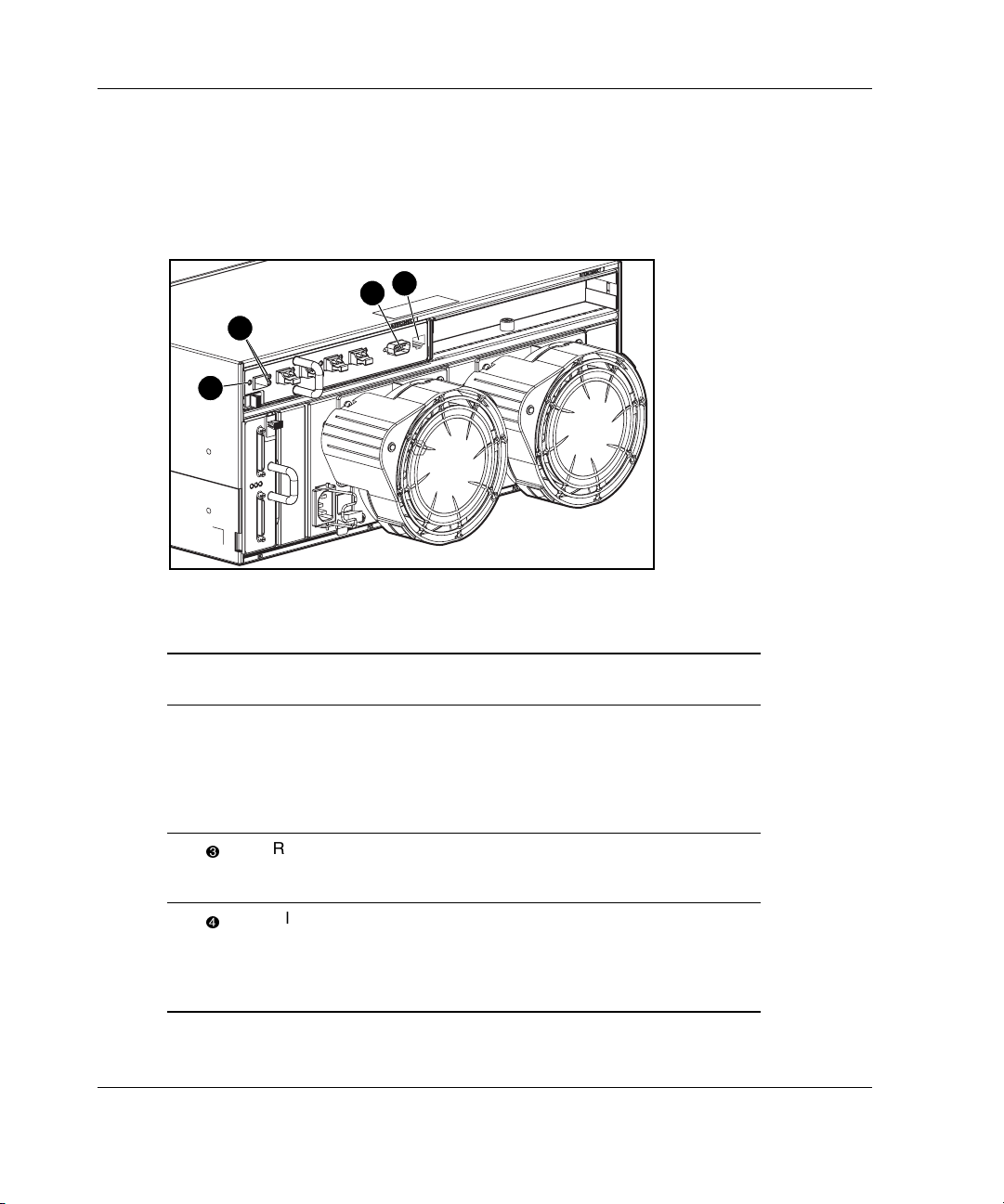
Rear View of the Modular San Array 1000
Figure 1-2 is an illustration of the rear panel of the MSA1000 with an MSA Fabric
Switch 6 installed.
3
2
1
4
Figure 1-2: MSA1000 rear panel with a Fabric Switch 6
Item Description Function
1-4 Modular SAN Array Fabric Switch 6 User Guide
Port Link Indicators See indicators table in Chapter 4,
“Troubleshooting.”
RS-232 DB-9 Serial
Port
RJ-45 Ethernet
connector
Global Status
Indicator
A male serial port that may be
connected to a host system with a
standard 9-pin female to 9-pin female
null modem cable. This port can be
used to perform initial configuration or
local management diagnostic tasks.
Ethernet connector to connect the
device to a network for management
purposes.
The Global Status Indicator provides a
visual reference to the status of the
switch. See the indicators table in
Chapter 4, “Troubleshooting,” for more
information.
Page 16

Installation
Before the MSA Fabric Switch 6 can communicate with Compaq-managed devices,
all devices must be properly connected and powered on.
Ethernet RJ-45 Cable
This connector is provided for management through Simple Network Management
Protocol (SNMP). By default, the MSA Fabric Switch 6 is configured to use an IP
address of 127.0.0.1. To change this IP address, use ACU-XE, a terminal, or a
terminal emulator connected to the DB-9 serial port. Refer to Chapter 2, “Initial
Configuration of the Switch,” for more detailed information on this subject.
DB-9 Serial Cable
This connector is provided for advanced configuration and management.
The MSA Fabric Switch 6 is designed to function directly out of its shipping
container with no special configuration required. However, you have the ability to
configure and monitor various aspects of the MSA Fabric Switch 6 by using
ACU-XE or CIM-XE or by connecting a terminal or terminal emulator to the serial
port. See Chapter 2, “Initial Configuration of the Switch,” for more information on
using this interface.
Overview of the Switch
Modular SAN Array Fabric Switch 6 User Guide 1-5
Page 17

Overview of the Switch
Hot-Pluggable
The MSA Fabric Switch 6 is hot-pluggable. The unit can be installed and replaced
without power-cycling the MSA1000.
When adding or replacing a switch, allow sufficient time to complete the power-on
self-tests (POST) and configuration tasks before using.
To power on the unit properly:
1. Power on the MSA1000.
On power up, the switch will run several POST tests and the GSI indicator will
display changing patterns (refer to the section “Reading the Global Service
Indicator” in Chapter 4, “Troubleshooting”).
2. Power on I/O device(s).
3. Verify that the storage device(s) are visible to the host(s).
4. Start Applications.
Before the MSA Fabric Switch 6 can communicate with Compaq-managed devices,
all devices must be properly configured, connected, and powered up. See Chapter 2,
“Initial Configuration of the Switch,” for installation instructions.
1-6 Modular SAN Array Fabric Switch 6 User Guide
Page 18

Initial Configuration of the Switch
This chapter details the procedures used to initially configure the MSA Fabric
Switch 6. Preliminary switch configuration includes entering the Ethernet and the
SNMP settings.
Two configuration methods are available:
• Using the text-based user interface to configure the switch
• Using the Array Configuration Utility-XE (ACU-XE) to configure the switch
2
Modular SAN Array Fabric Switch 6 User Guide 2-1
Page 19

Initial Configuration of the Switch
Configuration Overview
When a switch is initially connected to a network, the network does not recognize it
and does not know its IP address. Accessing the switch and entering the Ethernet and
SNMP settings assigns the switch a location and makes it available to the network.
After the switch is accessible, additional parameters must be entered. These
secondary configuration tasks can be performed from four different user interfaces,
including the text-based user interface (text-based UI), Command Line Interface
(CLI), the ACU-XE, and the Compaq MSA Fabric Switch 6 Management Utility.
The text-based UI can be used for the initial configuration tasks and the CLI can be
accessed from this interface to perform advanced configuration tasks.
The CLI of the switch provides access to extensive management and monitoring
functions and is available directly through the serial port in the front of the switch or
remotely through the switch’s Ethernet interface using telnet. During initial set-up, it
is accessed through the text-based UI. Subsequently, the system defaults to the CLI
or the text-based UI, depending on which interface was used last. For information on
the CLI, refer to Appendix C, “Command Line Interface.”
The ACU-XE is a web-based user interface primarily used to configure the array
controllers and hard drive arrays of the MSA1000. In addition, the ACU-XE can be
used to configure the switch. Instructions for configuring the switch using the
ACU-XE are included in this chapter. For information on using the ACU-XE to
configure the storage, refer to the StorageWorks by Compaq Modular SAN Array
1000 User Guide or the Compaq Array Configuration Utility XE User Guide.
The MSA Fabric Switch 6 Management Utility provides most of the functions
available in the text-based UI and the CLI, but in a user-friendly, web-based,
graphical interface. It is accessible from Compaq Insight Manager (CIM-XE) or any
workstations equipped with a web browser. For more information, refer to
www.compaq.com/storageworks.
2-2 Modular SAN Array Fabric Switch 6 User Guide
Page 20

Initial Configuration of the Switch
Using the Text-based UI to Configure the Switch
The text-based UI of the switch is available directly through the serial port in the
front of the switch. After the Ethernet settings are entered, the text-based UI can be
accessed remotely through the switch’s Ethernet interface using telnet.
following exceptions, all functions of the menu interface are available either directly
or through telnet.
• The telnet interface is available only after the MSA Switch is completely booted.
This means the results of the initialization tests are not viewable and if a reset is
issued, the telnet connection is terminated.
• Users are unable to change the password over the telnet interface.
Another difference between using the serial port interface and telnet is that when
using telnet, you can only get access to the switch after it has started
initialized its network parameters. Consequently, you
terminal to initially configure network
information of the MSA Switch
parameters and to view the power-up
.
Connecting a Terminal to the Switch
NOTE: This process uses a computer running on Microsoft Windows NT 4.0 or later.
However, the switch can communicate with any operating system that utilizes a terminal
emulator. If your computer uses another operating system, be sure that the baud rate, data
bits, stop bits, parity, and terminal emulation are set for the selected serial port as specified in
this procedure.
must have a directly-connected
With the
up and has
To directly connect a terminal to the MSA Switch:
1. Make sure there is power to the switch and attach a terminal or terminal
emulator.
2. Connect a server serial port to the switch’s DB-9 serial port.
3. Power on the server (if it is not already on).
4. Access the terminal emulator on the server. In Windows NT 4.0, select
StartProgramsAccessoriesHyperTerminal
Modular SAN Array Fabric Switch 6 User Guide 2-3
Page 21

Initial Configuration of the Switch
5. Set up the properties for the terminal connection.
In Windows NT 4.0:
a. Double-click the Hypertrm icon.
b. Enter a name for the connection in the New Connection dialog box, select an
icon to represent the switch for future use, and click OK.
The Connect To dialog box is displayed.
6. From the Connect using drop-down menu, select the communications port
assigned to the serial port (for example, COM1, COM2) and click OK. In the
properties dialog box, enter the following port settings and select OK.
Table 2-1: Default Serial Port Settings
Type Setting
Bits per second (baud rate) 38,600
Data bits 8
Parity None
Stop bits 1
Flow control None
7. Select FileProperties to show the connection properties dialog box. Select the
Settings tab. From the Emulation pull-down menu, select VT100 and click OK.
8. Power ON all peripheral device(s).
9. Wait at least ten seconds and power cycle the MSA1000. The switch sends a
series of Power-on Self-Test (POST) messages in HyperTerminal.
2-4 Modular SAN Array Fabric Switch 6 User Guide
Page 22
Logging in to the Text-based UI
Upon connection to the switch or completion of the start-up sequence, you must log
into the MSA Switch to access the management
as “user” and enter the password assigned to the switch.
Initial Configuration of the Switch
functions. To do this, you must login
The default login variables assigned
Login: user
Password: ADMIN
at the factory are:
To access the text-base UI:
1. At the Login prompt, enter user as the login variable.
>Login: user
2. At the password prompt, enter the assigned password.
>Password: ADMIN
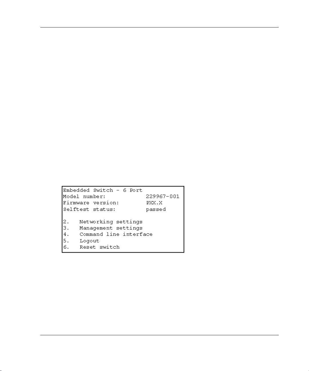
Upon successful login, the main menu is displayed. Figure 2-1 is an illustration
of the initial Login menu.
Figure 2-1: Login menu
The main menu contains a brief summary of the status of the switch, including the
number, the firmware version, and whether it passed its self-test.
model
NOTE: If the text-based UI from the previous connection was logged out while in the CLI, the
CLI prompt is displayed. To return to the text-menu interface from the CLI prompt, enter exit at
the prompt.
Modular SAN Array Fabric Switch 6 User Guide 2-5
Page 23
Initial Configuration of the Switch
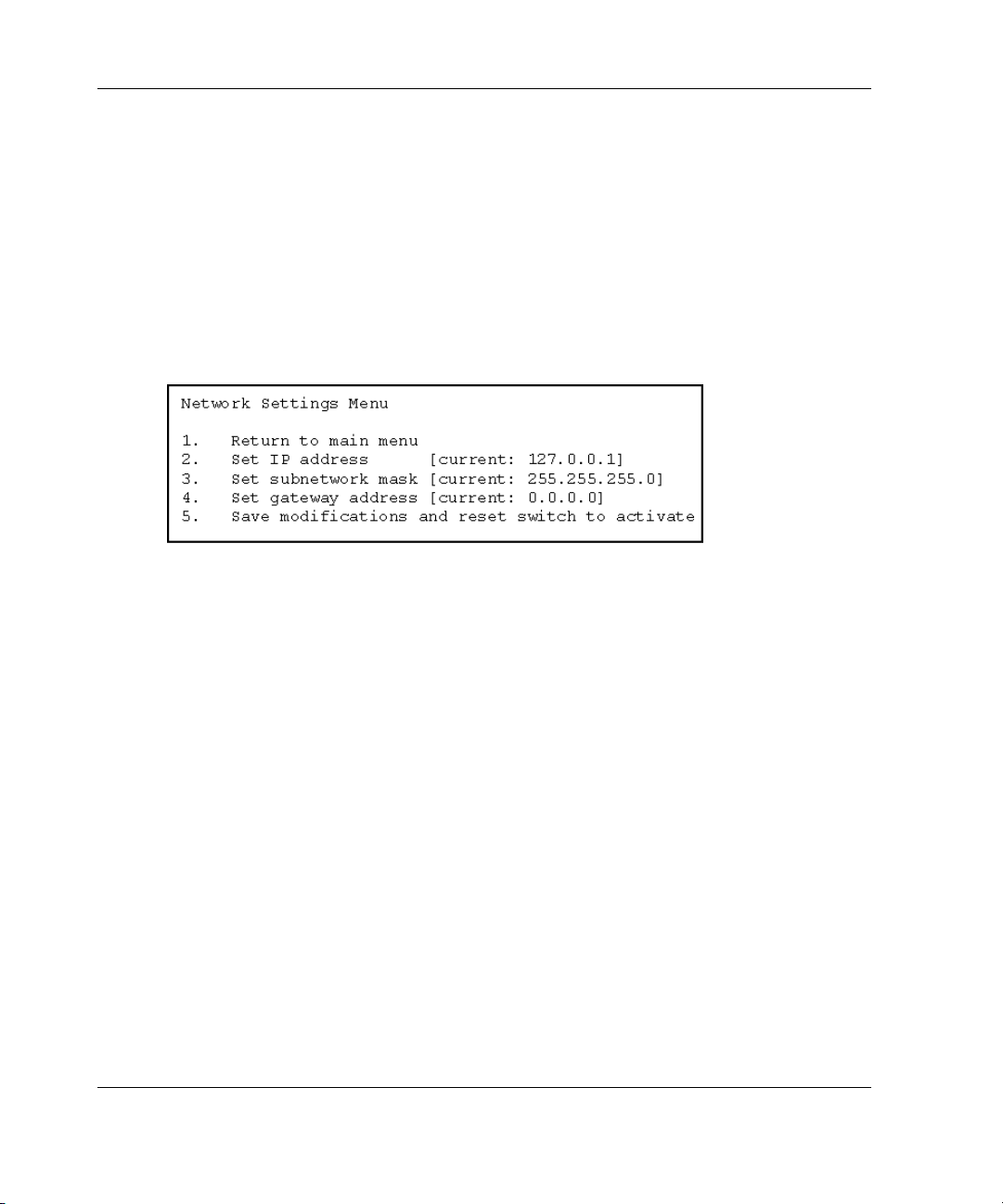
Accessing Networking Parameters
Select option 2. Networking parameters to access the Network Parameter menu,
which is shown Figure 2-2. The first option in this menu allows the user to return to
the main menu. Any changes made are reset to the previous value.
The second, third, and fourth parameters are used to configure the Ethernet settings
for the MSA Switch. All these parameters must be set appropriately for the site
before the MSA Switch can be managed over the Ethernet and connected to using
telnet.
Figure 2-2: Network Parameters menu
2-6 Modular SAN Array Fabric Switch 6 User Guide
Page 24
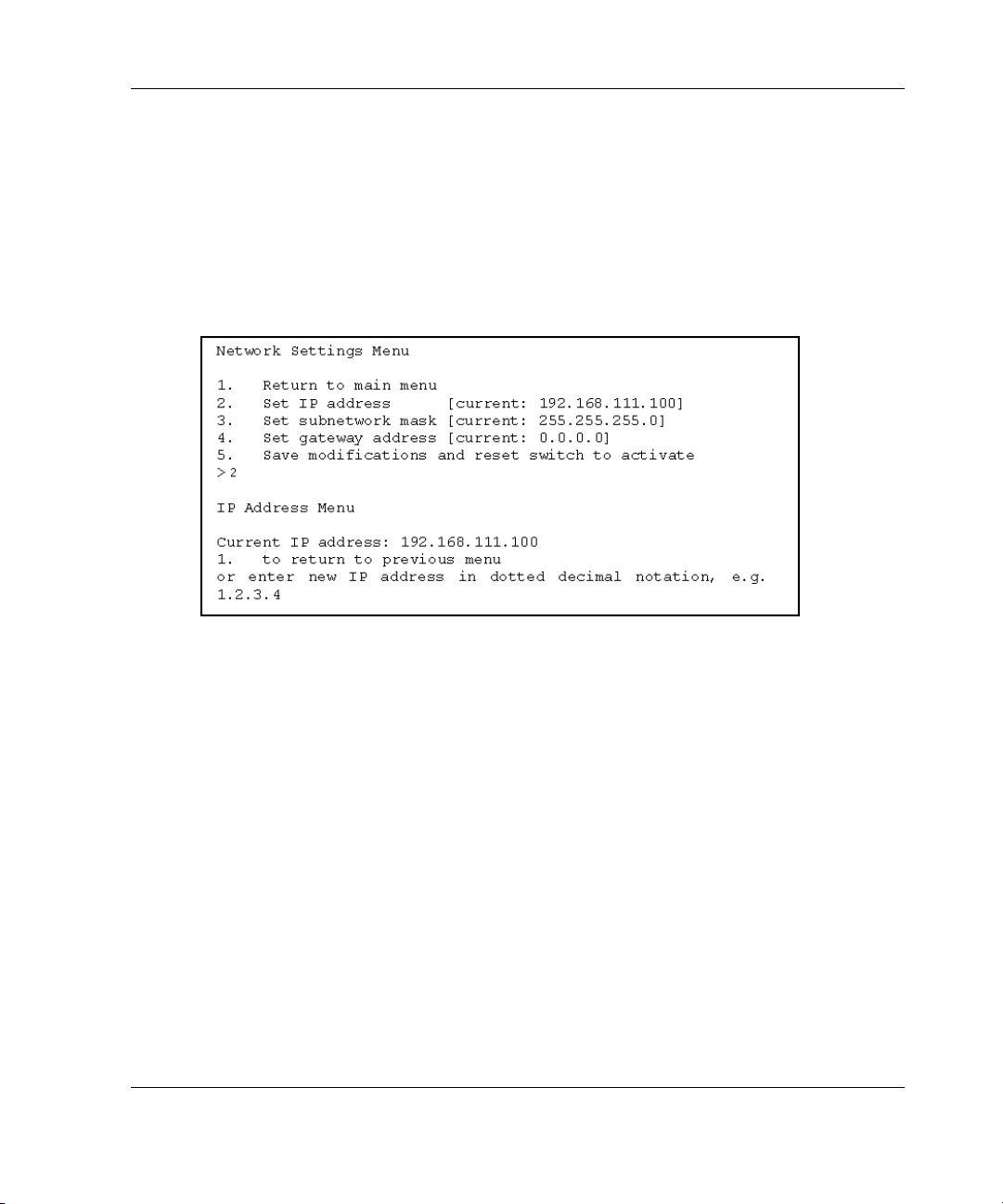
Setting the IP Address
Select option 2. Set IP address in the Network Parameters menu to call up the IP
Address menu shown in the figure below. It displays the current IP address. The
default (127.0.0.1) is set at the factory. This address should be changed to an IP
address appropriate to your site. Check with the network administrator if uncertain of
what this should be. Check with your network administrator before using the default
address, as it is a special IP address used for testing purposes only.
Figure 2-3: Network Parameters – Set IP address
Initial Configuration of the Switch
Modular SAN Array Fabric Switch 6 User Guide 2-7
Page 25
Initial Configuration of the Switch
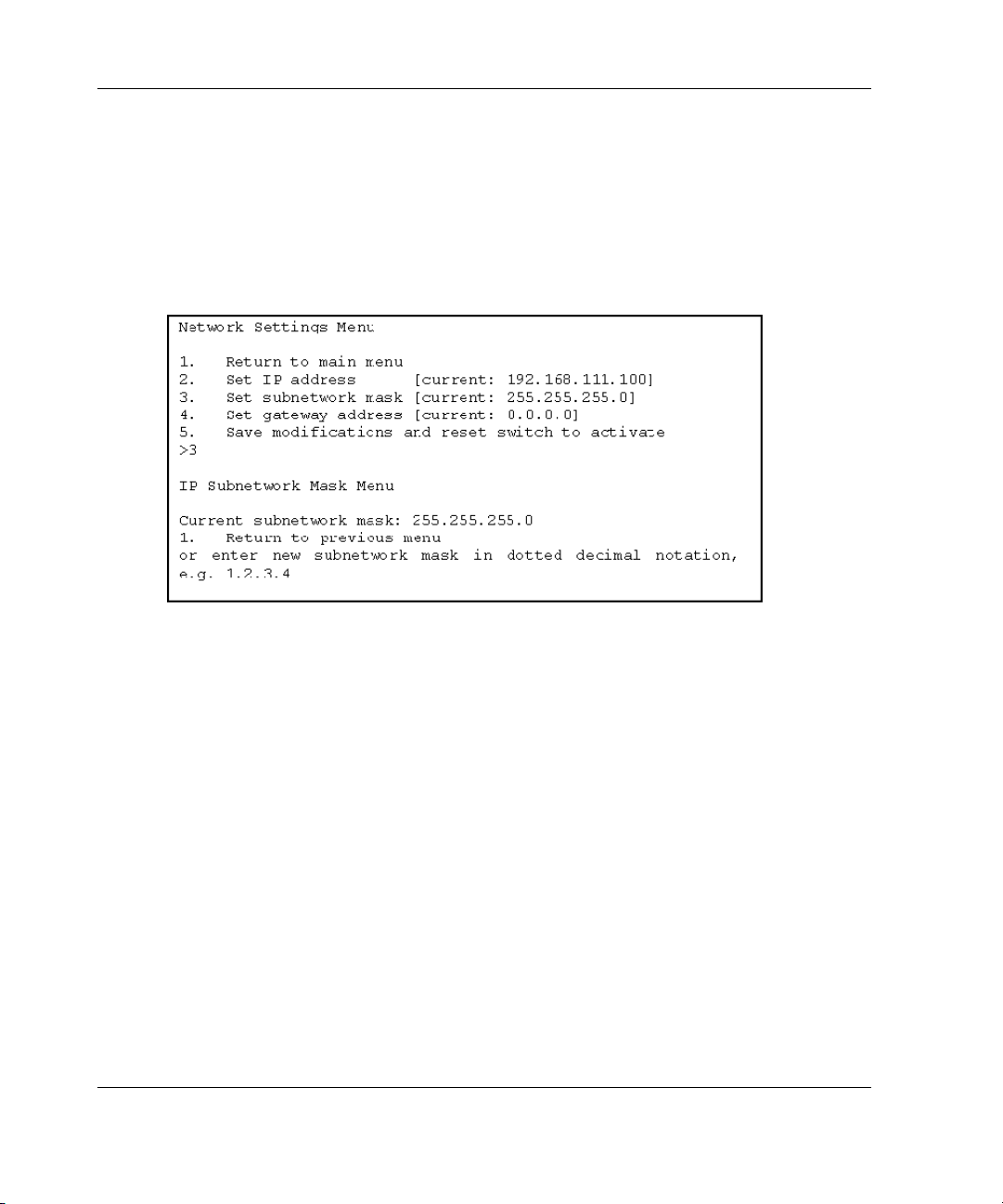
Setting the Subnetwork Mask
Select option 3. Set subnetwork mask in the Network Parameters menu to call up
the Subnetwork Mask Menu. The default subnetworking mask is a Class C mask as
shown in the figure below. This mask will work in many installations, as Class C IP
networks are by far the most common. The best source of the correct mask is your
local network administrator.
Figure 2-4: Network Parameters menu – Set subnetwork
mask
2-8 Modular SAN Array Fabric Switch 6 User Guide
Page 26
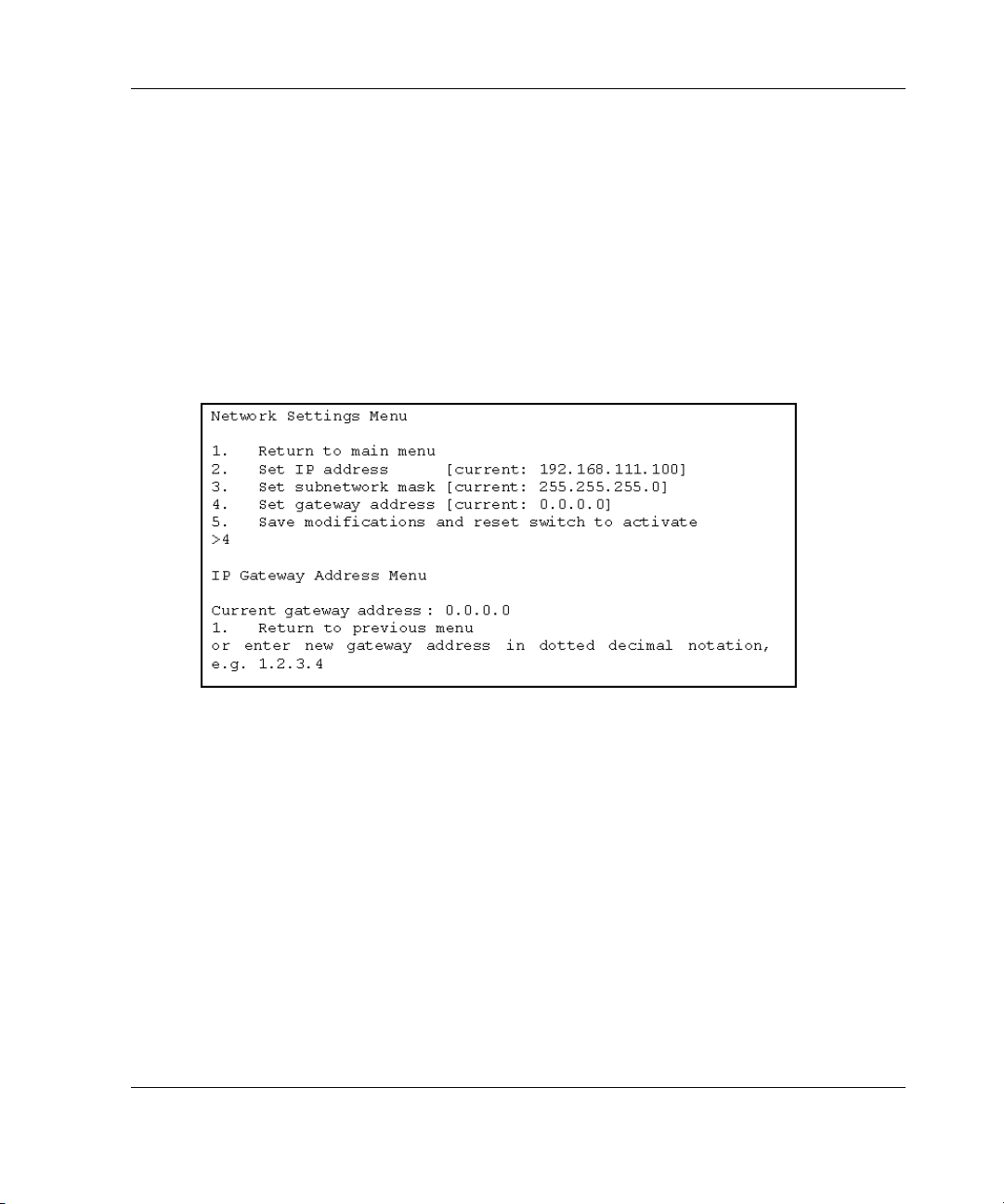
Setting the Gateway Address
Select option 4. Set gateway address in the Network Parameters menu to call up the
Set Gateway Address menu, which is shown in Figure 2-5.
The gateway is a computer or Ethernet router that connects your segment of the
Ethernet to other segments. This is also true if using telnet to communicate with the
MSA Fabric Switch 6 over the Ethernet from systems on other segments. In both of
these cases, the MSA Fabric Switch 6 will need the IP address of the gateway system
in order for it to function. Direct questions about gateways to your local network
administrator.
Initial Configuration of the Switch
Figure 2-5: Network Parameters menu – Set gateway
address
Saving Modifications
Though a number of parameters may have been set in the Network Parameters menu,
none are permanent until the Save modifications and reset switch to activate option
is chosen. This saves the parameters in non-volatile memory and reboots the switch
with the new parameters in effect.
Modular SAN Array Fabric Switch 6 User Guide 2-9
Page 27
Initial Configuration of the Switch
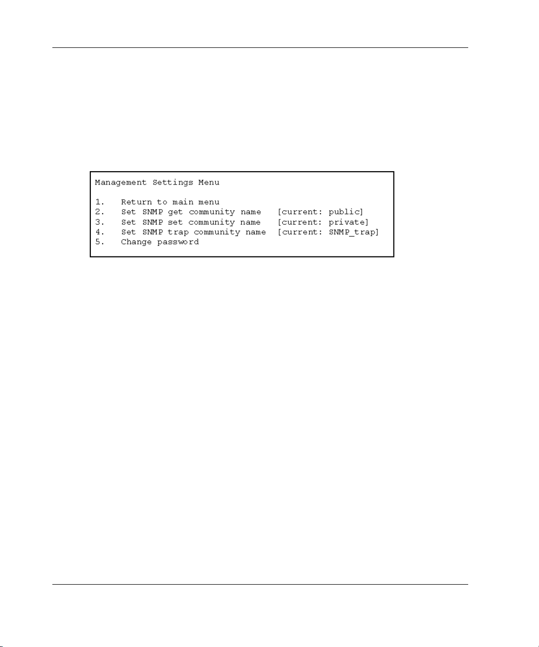
Accessing Management Parameters
Select option 3. Management settings in the main menu to call up the Management
Settings Menu, which is shown in Figure 2-6.
Unlike the Network Parameters menu, changes made in this menu become effective
as soon as they are made. There is no need to reset the switch.
Figure 2-6: Management Options menu
Options include:
1. Return to main menu allows the user to return to the main menu.
2. Set SNMP get community string calls up the SNMP Get Community Name
menu. This allows the user to restore the default SNMP get community name or to
enter a new SNMP get community name.
3. Set SNMP set community string calls up the SNMP Set Community Name menu.
This allows the user to restore the default SNMP set community name or to enter a
new SNMP set community name. The SNMP Set community string is the password
that any SNMP client must use to write settings to the SNMP agent on the MSA
Fabric Switch 6. This name can be any ASCII string desired. The factory default is
“private.”
4. Set SNMP trap community string calls up the SNMP Trap Community Name
menu. The SNMP Trap community string is the password that any SNMP client must
use to poll the SNMP agent on the MSA Fabric Switch 6 for SNMP traps. This name
can be any desired ASCII string. The factory default is “SNMP_trap.”
To change the SNMP Trap Community string, type the new name at the command
prompt and press the Enter key
2-10 Modular SAN Array Fabric Switch 6 User Guide
.
Page 28

5. Change Password is used to enter a new password. There will be verification to
test if this has been successfully completed or not. For security reasons, the password
can only be changed through the serial port. It cannot be changed through a telnet
connection over the Ethernet.
The password can be set to null (that is, a carriage return) or an alphanumeric
password can be used with up to eight characters. The space cannot be part of the
password as it is used to separate the first and second copies of the new password.
NOTE: If the new password is forgotten, contact your network administrator. You will need the
unit’s serial number and Ethernet MAC address.
Accessing the CLI
Select option 4. Command line interface on the main menu, to call up the command
line interface. This gives the user the ability to change parameters. These parameters
should only be modified by a knowledgeable user in order to modify the MSA
Switch operational parameters, to set up policies, as well as to troubleshoot problems.
The complete Command Line Interface is outlined in Appendix C, “Command Line
Interface.”
Initial Configuration of the Switch
Exiting the Text-based UI
The user can log out of the MSA Switch by selecting option 5. Logout in the main
menu. The original login prompt is redisplayed.
Resetting the Switch
Select option 6. Reset Switch in the main menu to reboot the switch. This should not
be done in a haphazard manner as all Fibre Channel connections provided by the
switch can be affected and any management data stored in the switch will be erased.
Modular SAN Array Fabric Switch 6 User Guide 2-11
Page 29

Initial Configuration of the Switch
Using the Array Configuration Utility-XE (ACU-XE) to Configure the Switch
When using the ACU-XE to initially configure the switch, depending on the
controller’s settings and the current switch configuration, you will be shown various
options. The ACU-XE will prompt for information through specific screens, allowing
changes before they are saved.
In addition to accessing the ACU-XE, the switch configuration process is separated
in to two parts:
• Initial switch configuration
• Advanced switch configuration
As discussed previously, initial switch configuration includes setting the IP address,
Subnet Mask, and Default Gateway of the switch (and the redundant switch, if
installed). Until these Ethernet and SNMP parameters are entered, a Web Browser
cannot find or connect to the switch.
Advanced switch configuration includes managing and monitoring ports, setting up
zoning, and upgrading the switch firmware. Advanced configuration tasks are
performed in using the MSA Fabric Switch 6 Management Utility. A link to this
utility is provided in the ACU-XE.
NOTE: The switch configuration utility Web link to the MSA Fabric Switch 6 Management
Utility is present only if the selected controller supports this feature.
NOTE: In the following screen examples, the configuring server’s IP address is
10.100.100.14. One switch has an IP address of 10.100.100.10 and the other switch’s IP
address is 10.100.100.11.
2-12 Modular SAN Array Fabric Switch 6 User Guide
Page 30
Initial Configuration of the Switch
Accessing the Switch Configuration Option of the ACU-XE
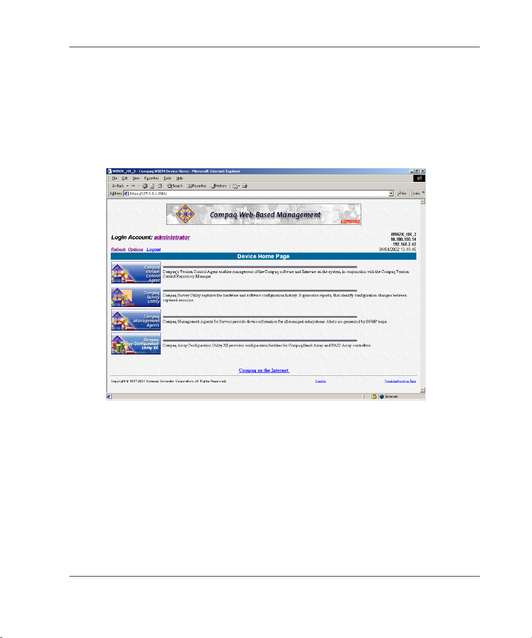
The ACU-XE can be started from the Compaq Web Based Management screen or
by selecting Start - Programs - Compaq System Tool - Compaq Array
Configuration XE.
Figure 2-7 is an example of the Compaq Web-Based Management screen.
Figure 2-7: Compaq Web-Based Management screen
To start the ACU-XE from the Web-based Management screen:
1. Select Compaq Array Configuration Utility XE.
The ACU-XE main screen is displayed. See Figure 2-8 for an illustration of the
ACU-XE main screen.
Modular SAN Array Fabric Switch 6 User Guide 2-13
Page 31

Initial Configuration of the Switch
2. In the main ACU-XE screen, select an MSA1000 Controller from the controller
list in the left column of the screen.
Three configuration methods are displayed at the bottom portion of the screen:
• Assisted Configuration is used to configure the controller.
• Advanced Configuration is used to configure the controller.
• Switch Configuration is used to configure the switch.
Figure 2-8: ACU-XE main screen
3. Select Switch Configuration.
All available switches detected by the ACU-XE for the selected controller are
listed.
In the example shown in Figure 2-9, two switches were detected.
2-14 Modular SAN Array Fabric Switch 6 User Guide
Page 32

Figure 2-9: Switch selection
Initial Configuration of the Switch
4. Select a switch to configure.
Modular SAN Array Fabric Switch 6 User Guide 2-15
Page 33

Initial Configuration of the Switch
Initial Switch Configuration
After a switch is selected in the Switch Configuration screen, available configuration
tasks for that switch are listed. See Figure 2-10 for an illustration of these
configuration task options.
During the initial configuration of the switch, only one option is displayed. If the
switch has already been configured and is active, additional tasks are displayed.
These additional tasks are discussed in the following section, “Advanced Switch
Configuration.”
To initially configure the switch:
1. Select ACU-XE Switch Configuration.
Figure 2-10: Initial Switch Configuration task option
An input screen is displayed. See Figure 2-11.
2-16 Modular SAN Array Fabric Switch 6 User Guide
Page 34

Figure 2-11: Switch parameters input screen
Initial Configuration of the Switch
2. Enter the following information:
• IP Address
• Default Gateway
• Subnet Mask
• Read and Write Community strings
3. Click Finish to save the settings.
4. Repeat these procedures to set up another switch, if necessary.
Modular SAN Array Fabric Switch 6 User Guide 2-17
Page 35

Initial Configuration of the Switch
Advanced Switch Configuration
After the initial configuration of the switch is completed, additional switch
configuration tasks become available.
As illustrated in Figure 2-12, links to the Switch Configuration Utility are displayed
for each switch. The Switch Configuration Utility is part of the MSA Fabric Switch 6
Management Utility that resides on the switch itself.
Parameters more advanced than those offered by ACU-XE are available in the
Management Utility.
Figure 2-12: Advanced switch configuration options
NOTE: Before using the Web-based Switch Configuration Utility, verify that the networking
cables have been connected between the management computer running ACU-XE and the
LAN management ports on the switch(es), usually through a Hub. Compaq recommends using
the PING command to ensure connectivity before selecting the Link.
2-18 Modular SAN Array Fabric Switch 6 User Guide
Page 36

MSA Fabric Switch 6 Management Utility
This chapter describes how to use the Management Utility on the MSA Fabric
Switch 6. The following sections describe the process to launch the Management
Utility on your switch:
• Defining System Requirements
• Launching the Management Utility
• Describing the Console
• Using the Management Utility
3
Modular SAN Array Fabric Switch 6 User Guide 3-1
Page 37

MSA Fabric Switch 6 Management Utility
Defining System Requirements
The MSA Fabric Switch 6 Management Utility runs as a Java applet in a Netscape or
Microsoft web browser and works with the versions shown below:
• Microsoft Internet Explorer version 5.5 or later
• Netscape Navigator version 4.75 or later
• Java Runtime Environment, Standard Edition, version 1.3.1 or later
The Java Plug-in must be already installed or be downloaded from the web or
installed from Modular SAN Array 1000 Support Software CD-ROM.
To download the Java plug-in from the Web:
1. Go to
http://java.sun.com/ using Netscape Navigator or Internet Explorer.
2. Select J2SE technology.
3. Select J2SE downloads.
4. Scroll down the list and select J2RE-1.3.1 or later (includes Java Plug-in 1.3.1
with bundled HTML Converter).
5. Follow the download instructions.
To install Java plug-in from the MSA1000 Support Software CD:
1. Insert the MSA1000 Support Software CD in CD drive of your Server.
2. Select Browse CD Contents.
3. Navigate to and select the Misc folder.
4. Click Windows_J2RE_Plug-in_1-4.exe and follow the instructions.
3-2 Modular SAN Array Fabric Switch 6 User Guide
Page 38

MSA Fabric Switch 6 Management Utility
Launching the Management Utility
To access your MSA Fabric Switch 6 using the Management Utility, you must
configure it with an IP address using the Array Configuration Utility-XE (ACU-XE),
as described in the section titled “Configuring your IP address," and be connected to
an IP network. Once configured, use the following procedure to launch the utility:
1. Use Compaq Insight Manager (CIM XE) or enter the IP address of the switch
you want to manage into the web browser’s address box.
2. Once the Utility is launched, enter the SNMP “Read Community” and “Write
Community” strings into the appropriate test boxes.
NOTE: These strings are case-sensitive.
3. Click the OK button.
Figure 3-1: SNMP screen
NOTE: If the display properties on your computer system are set to “256 colors,” the
Community Strings window will appear patterned and unclear. Change your display properties
setting to either “True Color (32 bit)” or “High Color (16 bit)” for a sharp, clear image. You will
find the display properties setting under Start\Settings\Control Panel\Display\Settings or
right-click your desktop and select Active Desktop\Customize\Settings.
Modular SAN Array Fabric Switch 6 User Guide 3-3
Page 39

MSA Fabric Switch 6 Management Utility
Describing the Console
The Management Utility provides a web-browser-based user interface so the MSA
Fabric switch 6 can be easily managed. The opening window, as shown in the figure
below, consist of three sections:
• Task Selection Toolbar
• Status Panel
• Main Management Panel
Figure 3-2: Console screen
3-4 Modular SAN Array Fabric Switch 6 User Guide
Page 40

Task Selection Toolbar
The Task Selection toolbar is comprised of five buttons and is located in the upper
left corner of the screen. Selecting one of these buttons determines which of the
management tasks you will operate using the Management Utility.
Figure 3-3 is sample of the Task Selection toolbar.
Figure 3-3: Task selection toolbar
Status Panel
The Status Panel is located at the bottom of the console screen and is shown in
Figure 3-4. It is comprised of the following four elements:
• Switch Status Indicators
• Message Text Line
• Progress Indicator Bar
MSA Fabric Switch 6 Management Utility
• Control Buttons, including Cancel, Clear Status, and Refresh.
Figure 3-4: Status panel
Modular SAN Array Fabric Switch 6 User Guide 3-5
Page 41

MSA Fabric Switch 6 Management Utility
Switch Status Indicators
The switch indicators in the Status Panel display the operating condition of the
switch, as described in the following table.
Table 3-1: Switch Status Indicators
TEMP Normal State Normal temperature operation. The operating temperature must be
kept between 10 and 40 degrees Celsius (between 50 and 104
degrees Fahrenheit).
Blinking Amber Chassis Temperature is in a Fault State and has not been
acknowledged. Clicking the icon brings up a display with more
information about the chassis operating condition and stops the
icon from blinking. The icon will also stop blinking if you click the
Clear Status button.
Amber Chassis Temperature is in a Fault State and has been
acknowledged by clicking the icon or clicking the Clear Status
button. A Chassis Temperature icon in the “Amber” fault state will
not return to the “Normal State” until the fault condition is corrected.
PORTS Normal State Normal port operation.
Blinking Amber One or more ports are in a Fault State and have not been checked.
Clicking the icon brings up a display with more information about
the ports operating condition and stops the icon from blinking. The
icon will also stop blinking if you click the Clear Status button.
Amber One or more ports are in a Fault State and have been checked by
clicking the icon or clicking the Clear Status button. A Ports icon in
the “Amber” fault state will not return to the “Normal State” until the
fault condition is corrected.
Message Text Line
The Message Text Line displays important information. This information can include
what events have occurred, what activities are being performed, and what error
messages are issued (in real-time).
3-6 Modular SAN Array Fabric Switch 6 User Guide
Page 42

MSA Fabric Switch 6 Management Utility
The following table lists the error messages shown on the Message Text Line. To
view detailed information about an error message, select the System Information
button and then the Events Tab or select the Port Information button then the
Events Tab.
Table 3-2: Message Text Line
EventPostFault
EventTempFaultAct
EventTempFaultDeact
EventPortStatus
EventRtChange
EventNsChange
Progress Indicator Bar
The Progress Indicator bar displays the percentage of progress completed during a
transfer of information between the MSA Fabric Switch 6 and StorageWorks
Management Utility, such as during a retrieval, refresh, or update action.
System event detected Alert
System event detected Alert
System event detected Alert
Port event detected Notify
Route event detected Notify
Name server event detected Notify
Modular SAN Array Fabric Switch 6 User Guide 3-7
Page 43

MSA Fabric Switch 6 Management Utility
Control Buttons
Three Control buttons are located next to the Progress Indicator bar. Their functions
are described in the following table.
Table 3-3: Control Buttons
Clear Status Clears the information in the message and progress
indicator areas. Switch Status Indicators that are
currently in the “Blinking Amber” state will be set to a
non-blinking “Amber” state. The indicators will not return
to the “Normal State” until the fault condition is corrected.
Cancel Cancels the current activity.
Refresh Contacts the MSA Fabric switch 6 being monitored and
refreshes the current display with current configuration
information. Clicking this button does not update
information for other Switches that are not currently
being displayed.
Main Management Panel
The Main Management panel is the section of the console that is used for most
management operations. The content of this panel is determined by one of the
following buttons:
• Port Information
• System Information
• Device View
• Session Configuration
• Help
3-8 Modular SAN Array Fabric Switch 6 User Guide
Page 44

Port Information
When the Port Information button is selected from the Task Selection toolbar, the
Port Information window is displayed as shown in the following figure. This display
consists of a graphic representation of the switch being monitored at the top of the
window, a tree representation of the switch, its ports, and connected devices in the
left portion of the window, and a set of five tabbed configuration panels.
• Port Summary Tab
• Port Events Tab
• Port Control tab
• Port Statistics Tab
• SFP Tab
If you select the switch from the menu tree, the Summary and Events tabs will be
available while the other tabs will be grayed out and unavailable. If you select a port
from either the switch graphic at the top of the window or the menu tree, the
Configuration, Statistics, and SFP tabs become available. These contain management
information about the port selected. The SFP tab will only be displayed if SFP
information is available for the port.
MSA Fabric Switch 6 Management Utility
NOTE: No SFP tab will be displayed when an SFP is not installed in the switch or when an
installed SFP does not make any information available.
Modular SAN Array Fabric Switch 6 User Guide 3-9
Page 45

MSA Fabric Switch 6 Management Utility
In addition, the indicators that are displayed on the switch graphic reflect the
indicators that are configured on the switch and display the same status that is
currently on the switch being monitored.
Figure 3-5: Port information (shown in the left panel)
3-10 Modular SAN Array Fabric Switch 6 User Guide
Page 46

System Information
When the System Information button is selected from the Task Selection toolbar,
you can manage and monitor global parameters for the switch. It provides a set of
tabbed panels that provide access to a set of 8 switch management functions and is
displayed in the following figure.
MSA Fabric Switch 6 Management Utility
Figure 3-6: System information window
Modular SAN Array Fabric Switch 6 User Guide 3-11
Page 47

MSA Fabric Switch 6 Management Utility
Device View
When the Device View button is selected, a table displays information for connected
devices, as shown in the following figure. The devices displayed in the table can be
filtered by selecting the switch, a port, or a device from the tree. Selecting the switch
will show all the devices, selecting a port will show only the devices connected to
that port, and selecting a device will show only that device.
Figure 3-7: Device view window
3-12 Modular SAN Array Fabric Switch 6 User Guide
Page 48

Session Configuration
When the Session Configuration button is selected, the SNMP settings are provided
for this session of the Management Utility application, as shown in the following
figure. They can be viewed or modified from this window.
MSA Fabric Switch 6 Management Utility
Figure 3-8: Main session
Modular SAN Array Fabric Switch 6 User Guide 3-13
Page 49

MSA Fabric Switch 6 Management Utility
Help
When the Help button is selected, the application information and service contact
information is provided as well as access to the on-line help system, as shown in the
following figure.
Figure 3-9: Main help session
3-14 Modular SAN Array Fabric Switch 6 User Guide
Page 50

MSA Fabric Switch 6 Management Utility
Using MSA Fabric Switch 6 Management Utility
The Management Utility lets you manage and monitor a Fabric Switch 6 remotely
through a web-browser interface. The following sections will help you to use the
Management Utility:
• Managing and Monitoring individual ports
• Managing from the system information panel
• Monitoring from the Device View
• Session Configuration
• Setting up Zoning
Each of these topics is discussed in the following sections.
Managing and Monitoring Individual Ports
The Port Information task is accessed by clicking the Port button in the Task
Selection toolbar as shown in Figure 3-10.
Modular SAN Array Fabric Switch 6 User Guide 3-15
Page 51

MSA Fabric Switch 6 Management Utility
Figure 3-10: Port button in task selection toolbar
This view provides information about configuration and operation of all of the ports
on the MSA Fabric Switch 6 being monitored. It also provides configuration and
operation information about individual ports that are selected from either the tree
representation or the switch graphic. It consists of the following five tabbed pages:
• Port Summary Tab
• Port Events Tab
• Port Control Tab
• Port Statistics Tab
• Port SFP Tab
Each of these tabs and their management functions is described in the following
sections.
3-16 Modular SAN Array Fabric Switch 6 User Guide
Page 52

Port Summary Tab
The Port Summary window is the default foreground display when the Port button
on the toolbar is clicked. It consists of a table that describes the status and
configuration of each of the ports on the switch. The following figure is an example
of this display.
MSA Fabric Switch 6 Management Utility
Figure 3-11: Port summary tab
The Port Summary window displays current information about the port as described
in the following table.
Modular SAN Array Fabric Switch 6 User Guide 3-17
Page 53

MSA Fabric Switch 6 Management Utility
Table 3-4: Port Summary Window
Parameters Description
Port Identifies the port described in the row by its port number.
Status Displays one of the following:
Failed Diagnostics = could not initialize the port; the port has
failed.
Loopback mode = loopback cable is attached.
Offline = port was taken offline by management.
No media installed = no SFP installed.
Link down = SFP is installed but with no link established.
Link up = SFP is installed and a link to the device is
established.
Link active = SFP is installed, a link to the device is
established, and traffic is flowing.
Isolated = it is understood that the other port is an E-port but
complete initialization cannot be established.
Media Type Identifies the media type plugged into the port or that no media
adapter is attached
Port Type Displays the worldwide name for the port identified.
3-18 Modular SAN Array Fabric Switch 6 User Guide
Page 54

Port Events Tab
The Port Events window is accessed by clicking the “Events” tab of the Port
Information display. It consists of a table that lists all of the ports related events
generated by the MSA Fabric Switch 6 being monitored as shown in the following
figure. This events table, as shown in the following figure, displays the parameters
described in the following table for each event logged.
MSA Fabric Switch 6 Management Utility
Figure 3-12: Port Events tab
Table 3-5: Port Events Window
Parameters Description
ID The sequential number indicating the order in which
the event was sent.
Time Stamp The time when the event was logged.
continued
Modular SAN Array Fabric Switch 6 User Guide 3-19
Page 55

MSA Fabric Switch 6 Management Utility
Table 3-5: Port Events Window continued
Parameters Description
Severity The severity level of the event. The possible severity
parameters are: Unknown, Emergency, Alert, Critical
Error, Warning, Notify, Info, Debug, and Mark.
Type The type of the event. The possible event type
parameters are: Unknown, Other, Status,
Configuration, Topology.
Description The message generated by the event.
Port Control Tab
The Port Control window is accessed by clicking the “Port Control” tab of the Port
Information display. The Port Control window consists of two boxes, Port
Configuration and Port Reset that provide port status information and port
configuration for the port selected. The figure that follows is an example of the Port
Control display.
Figure 3-13: Port info/Port Control tab
3-20 Modular SAN Array Fabric Switch 6 User Guide
Page 56

MSA Fabric Switch 6 Management Utility
The following figure provides an example of the Port Reset display (you must use the
scroll-bar at the right side of the panel to bring the Port Reset display into view).
Figure 3-14: Port info/Port Reset view
Modular SAN Array Fabric Switch 6 User Guide 3-21
Page 57

MSA Fabric Switch 6 Management Utility
The Port Control panel displays current information about the port as described in the
following table.
Table 3-6: Port Control Panel
Parameters Description
Status Displays one of the following:
Failed Diagnostics = could not initialize the port; the port has failed.
Loopback mode = loopback cable is attached.
Offline = port was taken offline by management.
No media installed = no SFP installed.
Link down = SFP is installed but with no link established.
Link up = SFP is installed and a link to the device is established.
Link active = SFP is installed, a link to the device is established, and
traffic is flowing.
Isolated = it is understood that the other port is an E-port but complete
initialization cannot be established.
Media Type Displays the media type plugged into the port or that no media interface
is installed.
Detected Port Type Indicates the current port configuration as an F-port, FL-port or E-port,
or other type port.
Set Port Type Allows you to configure the port as one of the following: F-port, FL-port,
E-port, Auto
Port State Displays and allows you to select these values:
On Line = Port is enabled on the Fibre Channel network.
Off Line = Port is disabled from operating on the Fibre Channel network.
continued
3-22 Modular SAN Array Fabric Switch 6 User Guide
Page 58

MSA Fabric Switch 6 Management Utility
Table 3-6: Port Control Panel continued
Parameters Description
Port Speed Displays and allows you to select these values:
1 Gigabit = Port is set to operate at 1Gbps
2 Gigabit = Port is set to operate at 2Gbps
Auto = Port will determine the operating speed of the attached device
(1Gbps or 2Gbps) and operate at that speed
Port Cost (100-5000) Allow you to tune or manually configure routing.
Port cost is used by routing in the shortest path calculation. Each
switch-to-switch connection is assigned a ‘cost’ based on the shortest
path calculation. The assigned path is determined by the smallest cost.
You will only change this value if you want to tune or manually configure
the routing (to force routing to select a different path). However, you
may wish to modify the cost value if you know the distance on one port
is much greater than on another port or if you know the port speeds are
different (1Gb vs. 2Gb).
Port Heartbeat (5-50) Allows you to manually adjust the number of times a heartbeat signal is
missed before routing decides the switch is not longer present. Port
heartbeat is used by routing to verify that a switch is still present.
Port Reset Use the scroll-bar at the right side of the panel to bring this option into
view. Port Reset allows you to reset the port to the previously set
parameters. Click the Reset Port to return to the previous port settings.
Modular SAN Array Fabric Switch 6 User Guide 3-23
Page 59

MSA Fabric Switch 6 Management Utility
Port Statistics Tab
The Port Statistics window is accessed by clicking the “Statistics” tab in the Port
Information display. It consists of the following three separate panels with statistics
for the port selected:
Transmitted/Received Statistics contains the port number monitored and the
number of occurrences of the parameters shown in the following table.
Table 3-7: Port Statistics tab
Parameter Description
Transmitted Frames The number of frames or packets transmitted out of this port.
Received Frames The number of frames or packets received at this port.
4-byte Words Transmitted The number of 4-byte words transmitted out of this port.
4-byte Words Received The number of 4-byte words received at this port.
Transmitted Broadcast Frames The number of broadcast frames or packets transmitted out of
this port. For a Fibre Channel loop, this is the number of OPNr
frames generated.
Received Broadcast Frames The number of broadcast frames or packets received at this
port.
Offline Sequences The number of times the system was unavailable for
meaningful work. For example, when the system was in selftest mode, configuration, and so on.
Rx/Tx 0-64 Byte Frames The number of frames of length between 0 - 64 bytes that
passed through this port.
Rx/Tx 65-127 Byte Frames The number of frames of length between 65 - 127 bytes that
passed through this port.
Rx/Tx 128-255 Byte Frames The number of frames of length between 128 - 255 bytes that
passed through this port.
continued
3-24 Modular SAN Array Fabric Switch 6 User Guide
Page 60

MSA Fabric Switch 6 Management Utility
Table 3-7: Port Statistics tab continued
Parameter Description
Rx/Tx 256-511 Byte Frames The number of frames of length between 256 - 511 bytes that
passed through this port.
Rx/Tx 512-1023 Byte Frames The number of frames of length between 512 - 1023 bytes that
passed through this port.
Rx/Tx 1024-1518 Byte Frames The number of frames of length between 1024 - 1518 bytes
that passed through this port.
Rx/Tx 1519-2148 Byte Frames The number of frames of length between 1519 - 2148 bytes
that passed through this port.
Error Statistics contains the number of occurrences of the statistics and error
parameters shown the following table. Except for Link Resets, all of the parameters
listed here are a part of the link error status block. You must use the scroll down to
bring this into view.
Table 3-8: Error Statistics
Parameter Description
Link Resets The number of link resets received at this port.
Link Failures The number of link failures.
Loss of Synchronization The number of instances of synchronization loss
detected at this port.
Loss of Signal The number of instances of signal loss detected
at this port.
Invalid CRC The number of invalid CRCs on the selected
port. Loop ports do not count CRC errors.
Invalid Transmission Words The number of invalid transmission words
received at this port.
continued
Modular SAN Array Fabric Switch 6 User Guide 3-25
Page 61

MSA Fabric Switch 6 Management Utility
Table 3-8: Error Statistics continued
Parameter Description
Primitive Sequence Protocol Errors The number of primitive sequence protocol
errors detected at this port.
Receive Frame Length Errors The number of frames with invalid lengths
received on this port.
Receive Frame Check Sequence The number of frames received with invalid
CRCs.
Receive Dropped Frames The number of frames that were dropped on
receive.
Transmit Dropped Frames The number of frames that were dropped on
transmit.
Stat Counter Reset — Contains a button that gives you the ability to reset the
statistical counters. Selecting this button will reset all the counters in the switch to
zero. You must use the scroll down to bring this into view. The following figures
provide an example of the Port Statistics tab, the Error Statistics View, and the Stat
Counter Reset view.
Figure 3-15: Port statistics tab
3-26 Modular SAN Array Fabric Switch 6 User Guide
Page 62

Figure 3-16: Error statistics view
MSA Fabric Switch 6 Management Utility
Figure 3-17: Stat counter reset view
Modular SAN Array Fabric Switch 6 User Guide 3-27
Page 63

MSA Fabric Switch 6 Management Utility
Port SFP Tab
The Port SFP window is accessed by clicking the “SFP ” tab in the Port Information
display. It allows you to view information about the SFP on the selected port from
any of the following categories: Transmitter, Operational, Vendor, Shortwave, and
Longwave.
Use the scroll-bar on the right side of the panel to view additional data. The
following figures provide examples of the Transmitter display, the compliance
parameter on the Transmitter display, the Operation display, the Vendor display, and
the Unformatted Data parameter on the Vendor Display.
Figure 3-18: SFP tab – transmitter display
3-28 Modular SAN Array Fabric Switch 6 User Guide
Page 64

MSA Fabric Switch 6 Management Utility
Figure 3-19: SFP tab – transmitter display, second part
Figure 3-20: SFP tab – operational display
Modular SAN Array Fabric Switch 6 User Guide 3-29
Page 65

MSA Fabric Switch 6 Management Utility
Figure 3-21: SFP tab – vendor display
Figure 3-22: SFP tab –vendor display, second part
3-30 Modular SAN Array Fabric Switch 6 User Guide
Page 66

MSA Fabric Switch 6 Management Utility
Managing from the System Information Panel
Selecting the System Information button brings up the System Information panels of
the Fabric Switch 6 Management Utility display. This display allows you to perform
a variety of management and monitoring functions relevant to the MSA Fabric
Switch 6 you are managing, as shown in the following figure.
Figure 3-23: System information panel
The System Information is used to manage switch-wide parameters and consists of
the following eight tabbed pages. These pages provide a variety of switch-wide,
management, and monitoring functions:
• Health Tab
• Information tab
• Switch Control Tab
• Network Tab
• Service Tab
• Firmware Tab
Modular SAN Array Fabric Switch 6 User Guide 3-31
Page 67

MSA Fabric Switch 6 Management Utility
• Backup/Restore Tab
• Events Tab
Each of these tabs and their management functions is described in the following
sections.
Switch Health Tab
The Switch Health window is the default tab that is displayed when the System
Information button is clicked for the first time. It can also be displayed by clicking
the “Health” tab. It consists of the following three separate boxes that provide
operating information about the switch being managed:
• Self-Test Status
• Thermal
• Up Time
The following figure provides an example of this display.
Figure 3-24: Switch health tab
3-32 Modular SAN Array Fabric Switch 6 User Guide
Page 68

The following table lists each of the parameters in this display.
Table 3-9: Switch health window
Panel Parameter Description
MSA Fabric Switch 6 Management Utility
Self-Test
Status
Thermal Temperature Status Status is presented as Passed if the internal
Up Time System Up Since The exact time that the system was last
POST Provides status of either Passed or Failed for
the Power On Self Test.
temperature of the chassis is below the
threshold temperature that is currently set or
Failed if it is above. The operating temperature
of the switch must be kept between 10 and 40
degrees Celsius (between 50 and 104 degrees
Fahrenheit).
Temperature Reading Current internal temperature of the chassis.
Temperature Threshold The current threshold temperature for the
switch is presented in a text box. This threshold
temperature can be changed by entering a new
variable and clicking the Set button within the
“Thermal” panel.
powered-up.
Cumulative
Up Time
The amount of time in hours that the switch has
been running since manufacture.
Modular SAN Array Fabric Switch 6 User Guide 3-33
Page 69

MSA Fabric Switch 6 Management Utility
Information Tab
The Information window is accessed by clicking the “Information” tab of the System
Information display. It consists of two separate panels that provide identification and
firmware version information about the switch being managed. The following figure
is an example of this display.
Figure 3-25: Switch info tab
3-34 Modular SAN Array Fabric Switch 6 User Guide
Page 70

MSA Fabric Switch 6 Management Utility
The following table lists each of the parameters in this display.
Table 3-10: Switch Info Window
Panel Parameter Description
Identification Device Description Product Name of the MSA Fabric Switch 6 that is
being managed.
Device SN Serial number of the switch being managed.
MAC address MAC address of the switch being managed.
World Wide Name World Wide Name of the switch being managed.
Firmware
Version
Fabric Switch 6 Version Firmware revision number of the firmware base
package within the switch being managed.
Modular SAN Array Fabric Switch 6 User Guide 3-35
Page 71

MSA Fabric Switch 6 Management Utility
Switch Control Tab
The Switch Control window is accessed by clicking the “Switch Control” tab of the
System Information display. It consists of three panels: “Switch Configuration,”
“Switch Reset,” and “Restore Factory Defaults” as shown in the following figure.
Figure 3-26: Switch control tab
3-36 Modular SAN Array Fabric Switch 6 User Guide
Page 72

MSA Fabric Switch 6 Management Utility
The following table lists each of the parameters in this display. The parameters in this
configuration are set by typing the new value into a text box or selecting a radio
button and clicking the Apply button in the Switch Configuration box. The Reset
Values button in the Switch Configuration box returns the parameters to their
previous settings.
Table 3-11: Switch Control Window
Parameter Description
Switch Role Displays whether switch is configured as the Principal switch or a Subordinate
switch in the Fabric.
Name Displays the system-generated switch name:
• Switch installed in slot 1: MSA1000 name-switch1
• Switch installed in slot 2: MSA1000 name-switch2
Priority (1-255) This parameter allows you to determine the priority that this switch will have
compared to other devices if it requests Fabric resources at the same time as
other devices. The variable is used during the SW-2 principal switch selection
process. Any number between 1 and 255 can be used for this setting. A lower
number results in a higher priority for the switch. The switch with the lowest
priority number will become the principal switch. If two switches have the same
“lowest priority number”, then the switch with the lowest WWN number will
become the principal switch.
A priority 1 forces the switch to be principal; a priority 255 will never allow the
switch to be principal switch. Priority 2 is reserved for the current elected
principal switch. The principal switch will change its priority to 2 if its priority is
greater than 2.
Desired Domain
(1-239)
Actual Domain Displays the current domain.
Address
Translation
Any number between 1 and 239. For inter operability, each switch in a Fabric
must have a different domain number. You can specify the desired domain.
However, the actual domain that is set may be different (for example, if the
domain is already in use). This domain number is used during SW-2 principal
switch selection.
Address translation allows you to address devices with private addresses
through the Fabric. The port must be private for this to function. Choose the
correct radio button to turn address translation on or off. This is limited to private
targets.
continued
Modular SAN Array Fabric Switch 6 User Guide 3-37
Page 73

MSA Fabric Switch 6 Management Utility
Table 3-11: Switch Control Window continued
Parameter Description
Send Fabric Address
Notification
Force IOD State Allows you to determine whether delivery of frames is completed in-
Forced IOD Delay (1-60
sec.)
Reset Switch This allows you to reset the switch. Use with caution as this will disrupt
Restore Factory Defaults Restores the settings enabled at the factory.
Fabric Address Notification (FAN) frames are sent by the Fabric to
notify public loop devices about their node ID and address. The default
setting is No.
Choosing Yes configures the switch to send Fabric Address
Notification frames.
Choosing No configures the switch to not send Fabric Address
Notification frames.
order or out-of-order. Out-of-order delivery can happen when a trunk
failure occurs in the fabric and traffic is rerouted around the failure.
Choosing On enables Forced In Order delivery when the fabric
topology is changed. Use with care as enabling this feature will cause
a delay when a trunk failure occurs.
Choosing Off disables Force In Order delivery and allows out-of-order
delivery. Note that some legacy devices cannot handle out-of-order
delivery and will require that this feature be enabled on all switches.
This is the delay time for Force In Order Delivery (if enabled). It
specifies the delay time before rerouting traffic to an alternative trunk.
The minimum delay time is 1 second; the maximum delay is 60
seconds. Set this parameter to greater than the E_D_TOV time of the
legacy device that requires in order delivery.
switch operations.
3-38 Modular SAN Array Fabric Switch 6 User Guide
Page 74

Network Tab
The Network window is accessed by clicking the “Network” tab of the System
Information display. It consists of the following two panels:
• IP Configuration
• SNMP Trap Management Stations
NOTE: The System Information - Network Tab page will not function properly without a valid
gateway address. If you are using the default gateway address (0.0.0.0) or an invalid gateway
address, you will need to change the address to a valid one. To check the gateway address on
your system using the CLI, see the section titled “NetCfg”. To change the gateway address
using the CLI, see the section titled “Setting the Gateway Address.”
IP Configuration This panel, as shown in the following figure, displays all of the IP
networking parameters that were set on the Fabric Switch 6 using the serial interface.
MSA Fabric Switch 6 Management Utility
Figure 3-27: Network tab
Modular SAN Array Fabric Switch 6 User Guide 3-39
Page 75

MSA Fabric Switch 6 Management Utility
The following table lists the parameters of this panel.
Table 3-12: Network tab
Parameter Description
IP Address Displays the IP address assigned to the MSA Fabric
Switch 6.
Subnet Mask Displays the subnet mask assigned to the MSA Fabric
Switch 6.
Default Gateway Displays the default gateway assigned to the MSA
Fabric Switch 6.
MAC Address Displays the MAC address of the MSA Fabric Switch 6.
SNMP Trap Management Stations— This panel, as shown above in Figure 3-27,
allows you to add and remove stations that have SNMP traps forwarded to them.
• To add a station, type its IP address and Port Number in the top text boxes in this
panel and click the Add button.
• To remove a station from receiving traps from this Fabric Switch 6, highlight its
IP address in the list box at the bottom of this panel and click the Remove button.
• To apply the changes, click the Apply button. To undo all the changes and reset
the display to the original settings, click the Reset button.
NOTE: The port number entered should be a valid port address. Most systems support a
range of 1-65534.
3-40 Modular SAN Array Fabric Switch 6 User Guide
Page 76

Service Tab
The Service window is accessed by clicking the “Service” tab of the System
Information display. It consists of the “Location and Contact Information” panel as
shown in the following figure.
MSA Fabric Switch 6 Management Utility
Figure 3-28: Service tab
This window allows you to read the location and contact information that is currently
configured for the switch and to modify it by selecting it and editing.
All the information in this panel is for informational purposes only. The switch does
not use any of this information to perform functions. For example, the switch will not
send out emails to the email address listed. However, some management applications,
including future versions, may display some of the information listed on the Service
tab page.
Modular SAN Array Fabric Switch 6 User Guide 3-41
Page 77

MSA Fabric Switch 6 Management Utility
Firmware Tab
The Firmware window is accessed by clicking the “Firmware” tab of the System
Information display. This window, as shown in the figure below, allows you to
download new firmware to your MSA Fabric Switch 6. To perform a download using
this interface, fill in the text boxes, click the appropriate radio button, and click the
Start Download button.
Figure 3-29: Firmware tab
3-42 Modular SAN Array Fabric Switch 6 User Guide
Page 78

MSA Fabric Switch 6 Management Utility
The following table lists the parameters in the “Download Control” panel.
Table 3-13: Firmware Window
Parameter Description
Current Version Displays the version of the firmware currently on the Fabric switch 6.
File Name Enter the file name of the file that you want to download.
TFTP Server IP
Address
TFTP Time-out (msec) Enter the time in milliseconds that you want the switch to wait after
TFTP Retries Enter the number of times you want the switch to try downloading the
Last Download Status This parameter reports either success or failure for the last download
Download Only Click this radio button if you want the switch to download the new
Download & Reboot Click this radio button if you want the switch to download the new
Enter the IP address of the TFTP Server from which you want to
download the new firmware.
requesting a download before requesting again.
new firmware before quitting.
operation.
firmware without rebooting. You must reboot the switch for the new
firmware to become operable.
firmware and then reboot the switch. The new firmware becomes
operable when the switch is rebooted. You will need to reload the Applet
after the switch is rebooted.
Note: Resetting the switch disrupts the network. This may affect
performance, but does not corrupt the data on the disk drives attached to
the switch. It does, however, erase any statistics and other management
data that has been collected.
Modular SAN Array Fabric Switch 6 User Guide 3-43
Page 79

MSA Fabric Switch 6 Management Utility
Backup/Restore Tab
The Backup/Restore window is accessed by clicking the “Backup/Restore” tab of the
System Information display. It consists of one panel titled: “Backup and Restore
Settings.” Using this interface, you can save the current configuration parameters of
the switch to a named TFTP server. You can also restore any previously saved
configuration to the switch.
To perform either a backup or restore operation, enter the correct parameters for
“Backup/Restore File Set” and “TFTP Server IP Address” and click either the
Backup or Restore button.
CAUTION: TFTP servers will create new files with modified filenames, resulting in
‘restore’ not retrieving the expected file. Be sure to verify that the TFTP server you
are using overwrites existing files to avoid this issue.
The following figure is an example of the Backup/Restore tab.
Figure 3-30: Backup/Restore tab
3-44 Modular SAN Array Fabric Switch 6 User Guide
Page 80

MSA Fabric Switch 6 Management Utility
The following table lists each of the parameters in this display.
Table 3-14: Backup/Restore tab
Parameters Description
Backup/Restore File Set The name for the set of files that contains
the backup configuration.
TFTP Server IP Address The IP address of the TFTP server that you
want to save a configuration file to or
restore a configuration file from.
Last Backup/Restore Status Displays the status of the last
backup/restore action performed on the
switch. The status will be “Status Unknown”
if there has not been a Backup/Restore
action since the last time the switch was
started.
Modular SAN Array Fabric Switch 6 User Guide 3-45
Page 81

MSA Fabric Switch 6 Management Utility
Events Tab
The Events window is accessed by clicking the “Events” tab of the System
Information display. It consists of a table that lists all of the events generated by the
switch being
monitored as shown in the following figure. Also included on this page
are two list-filtering options, System Events and Port Events.
Figure 3-31: Events tab
3-46 Modular SAN Array Fabric Switch 6 User Guide
Page 82

MSA Fabric Switch 6 Management Utility
This Event log, as shown in the above figure, displays the parameters described in the
table below for each event logged.
Table 3-15: Events Window
Parameter Description
Show: System Events Selecting System Events will filter the list so that only the events
related to the system (and not the individual ports) will be listed.
Selecting both System Events and Port Events will display all the
events.
Show: Port Events Selecting Port Events will filter the list so that only the events related to
the ports (and not the entire system) will be listed. Selecting both
System Events and Port Events will display all the events.
ID The sequential number indicating the order in which the event was
sent.
Time Stamp The time when the event was logged.
Severity The severity level of the event. The possible severity parameters are:
Unknown, Emergency, Alert, Critical, Error, Warning, Notify, Info,
Debug, Mark.
Type The type of the event. The possible event type parameters are:
Unknown, Other, Status, Configuration, Topology.
Description A description of the event.
Modular SAN Array Fabric Switch 6 User Guide 3-47
Page 83

MSA Fabric Switch 6 Management Utility
Monitoring from the Device View
Selecting the Device View button brings up Device View display. This display
allows you to monitor devices connected to the switch, as shown in the following
figure.
Figure 3-32: Device view
Depending on the icon selected in the tree, the Device View provides the following
information about the switch, the ports, or the devices connected to the switch.
Selecting members from the tree acts like a list filter. Selecting the switch in the tree
will list information about all the devices connected to the switch. Selecting a port in
the tree will list information about the selected port only. Selecting a device in the
tree will list information about the selected device only.
• Port — The port number on the switch.
• Node Type — The type of device connected to the port. For example, Storage
Device, or Raid Array. In cases where it is not possible to determine the device
type, it will be listed as “unknown.”
• Remote Port Type — The type of port on the attached device.
3-48 Modular SAN Array Fabric Switch 6 User Guide
Page 84

• WWN — The World Wide Name of the device connected to the port.
• WWPN — The World Wide Port Name of the device connected to the port.
Session Configuration
Selecting the Session Configuration button allows you to view the current SNMP
settings used by the Fabric Switch 6 and change them by typing new values in the
text boxes.
• To change a value, type the new values in the text boxes and click Apply.
• To return the settings to their previous values, click Reset.
NOTE: If the community strings specified do not match what is configured in the switch, the
application will not be able to communicate with the switch.
The parameters for Session Configuration are described in the following table.
Table 3-16: Session Configuration Window
Parameter Description
MSA Fabric Switch 6 Management Utility
Polling Rate This setting allows you to specify the rate for detecting the changes of devices in
the network or changes in the device environment status. Valid values are 13600(sec).
Timeout When the Fabric Management Utility issues a request to a managed device, if the
device fails to respond, it waits for a specified number of milliseconds and then
retries its request. This parameter sets the amount of time that the switch utility
waits before it retries its request. Valid values are 500-5000 (ms).
The timeout for each retry is increased exponentially. For example, if the timeout
value is set to 5000 ms and retry is set to 2:
• The initial attempt will time out in 5000 ms.
• The first retry will time out in 10000 ms.
• The second retry will time out in 20000 ms.
Compaq recommends that you set the retry count low if the timeout value is high.
continued
Modular SAN Array Fabric Switch 6 User Guide 3-49
Page 85

MSA Fabric Switch 6 Management Utility
Table 3-16: Session Configuration Window continued
Parameter Description
Retry Count The number of times that Management Utility will issue requests to the managed
device before reporting a loss of connection. Valid values 0-4.
Read
Community
Write
Community
NOTE: If the display properties on your computer system are set to “256 colors,” the
Community Strings window will appear patterned and unclear. Change your display properties
setting to either “True Color (32 bit)” or “High Color (16 bit)” for a sharp, clear image. You will
find the display properties setting under Start\Settings\Control Panel\Display\Settings or rightclick your desktop and select Active Desktop\Customize\Settings.
SNMP Read Community string is the password required to read management
data from the switch. This value must match the setting for the switch that you are
managing as it was set using the Command Line Interface (CLI). If the values do
not match, the application will not be able to retrieve information from the switch.
SNMP Write Community string is the password required to write management
data to the switch. This value must match the setting for the switch that you are
managing as it was set using the Command Line Interface (CLI). If the values do
not match, the utility will not be able to modify any values in the switch.
If the community strings specified do not match what is configured in the switch,
the application will not be able to communicate with the switch.
Setting up Zoning
Zoning is a function of the MSA Fabric Switch 6 that allows you to create isolated
Fibre Channel networks with a limited number of connected devices. By limiting the
number of devices in a zone, you can obtain more robust performance and enhance
access protection.
Zoning is compliant with the following standards:
• FC-SW-2
• FC-GS3
• FC-MI
3-50 Modular SAN Array Fabric Switch 6 User Guide
Page 86

This section describes the zoning functions supported by the MSA Fabric Switch 6. It
describes zoning at the individual switch and describes how the
functions are used to support zoning across a Fabric.
Zoning Elements
Before setting up zoning, you must understand the following zoning elements:
• Zone Members
• Zones
• Zone Sets
CAUTION: Never add a zoned switch to an established fabric that has no zoning. If
a switch configured with zoning is added to a fabric that has no configured zoning,
the fabric’s HBAs and targets will no longer be able to communicate and the traffic in
the fabric will be disrupted. For best results, only add a switch configured with zoning
to a fabric configured with the same zoning configuration.
Zone Members
MSA Fabric Switch 6 Management Utility
merge command
Zone members are Fibre Channel edge devices that are identified by their World
Wide Port Name (WWPN). Any device that you want to include in a zone must be
identified as a zone member. While internally the zone members are tracked by their
WWPN, you can create a Zone Member Name that acts as an alias for the device.
This makes it easier to identify the devices during configuration and operation. The
following are examples of Fibre Channel devices that can be named as zone
members:
• Servers
• Raid systems
• Disk drives
• Tape libraries
IMPORTANT: The World Wide Node Name (WWNN) of the Fibre Channel device cannot be
used to create a zone member. WWNN-bases zoning is expressly prohibited in the FC-MI
standard. Use World Wide Port Name (WWPN) to create a zone member.
Modular SAN Array Fabric Switch 6 User Guide 3-51
Page 87

MSA Fabric Switch 6 Management Utility
Zones
Zones are logical entities that represent groupings of zone members. Each zone must
be assigned a unique zone name when it is defined.
Zone Sets
Zone sets are logical entities that represent groupings of zones. They define a zoning
configuration. Each zone set is assigned a unique zone set name when it is defined.
The MSA Fabric Switch 6 allows storing of multiple zone sets. However, only one of
these zone sets can be active at a time. The other zone sets can be used as backup,
trials, or other user-defined configurations.
Naming Rules for Zone Members, Zones, and Zone Sets
Zone member, zone, and zone set names must follow these rules:
• Names must be between 1 and 64 characters long
• Characters used in names must be 7 bit ASCII characters
• The first character of a name must be a letter (a-z) and can be either upper case or
lower case
• Other characters of the name (any characters besides the first character) can be a
letter (a-z, either upper or lower case), a number (0-9), or a symbol ($ - ^ _).
• No spaces are allowed in the name
3-52 Modular SAN Array Fabric Switch 6 User Guide
Page 88

MSA Fabric Switch 6 Management Utility
Zoning Limitations for Zone Members, Zones, and Zone Sets
There are zoning limitations for individual switches and fabrics. See Table 3-17 for
maximum limitations.
Table 3-17: Switch and Fabric Zoning Limitations
Item Maximum
Number of Zone Sets 4
Number of Zones 64
Number of Zone Members 64
Two Ways to Display Zoning
The MSA Fabric Switch 6 Management Utility allows you to display zoning in two
ways:
• Merged zones
• Local zones
To toggle between the Merged Zones display and the Local Zones display, expand
the Zoning View drop-down list in the Zoning Configuration screen.
Merged Zones
Use the Merged Zones display when you are interested in viewing information for
zones merged with other switches on the Fabric.
This view is read-only and cannot be edited. The Merged Zones view is a
Fabric-wide display showing the merged zones with other switches on the fabric.
NOTE: Because only one Zone Set can be active across the entire Fabric, only the Active
Zone Set is shown.
Modular SAN Array Fabric Switch 6 User Guide 3-53
Page 89

MSA Fabric Switch 6 Management Utility
Local Zones
Use the Local Zones display when you are interested in viewing, creating, or editing
zone sets, zones, and zone members for the switch presently being monitored.
This view is a read/write single-switch display showing the zone sets, zones, and
zone members for that switch. You can create, edit and remove zone sets, zones, and
zone members using the Local Zones view.
Using the Fabric Switch 6 Management Utility to Configure Zoning
This section describes how to use the MSA Fabric Switch 6 Management Utility to
configure Zone Members, Zones, and Zone Sets and how to apply the new or edited
zone configurations to the switch.
Setting up Zoning includes:
• Enabling Zoning
• Creating Zone Sets
• Creating Zones
• Creating Zone Members
• Assigning Zone Members to Zones
• Assigning Zones to Zone Sets
• Activating the Zone Set
Each of these procedures is discussed in the following paragraphs.
3-54 Modular SAN Array Fabric Switch 6 User Guide
Page 90

MSA Fabric Switch 6 Management Utility
Enabling Zoning
IMPORTANT: The Zoning icon and its options are not displayed or accessible until Zoning is
enabled.
To enable zoning:
1. In the Switch Control tab of the System Information screen, select the Zoning
Configuration On radio button.
Figure 3-33 is an illustration of the Zoning Configuration option in the Switch
Control tab.
2. Click Apply to accept the change.
The Zoning icon is now displayed next to the other icons at the top of the screen.
Figure 3-33: Zoning Configuration option, Switch
Control tab
Modular SAN Array Fabric Switch 6 User Guide 3-55
Page 91

MSA Fabric Switch 6 Management Utility
Creating Zone Sets
To create a Zone Set:
1. Select the Zoning icon.
The Zoning Configuration screen is displayed. Figure 3-34 is an illustration of
the Zoning Configuration screen.
IMPORTANT: To create or edit Zone Sets, Zones, and Zone Members, the Local Zones
view must be displayed. To change the view in the Zoning Configuration screen, expand
the Zoning View drop-down box near the top-center of the screen.
Figure 3-34: Zoning Configuration screen, Local Zones
view
3-56 Modular SAN Array Fabric Switch 6 User Guide
Page 92

MSA Fabric Switch 6 Management Utility
2. To create a new Zone Set:
a. In the Zone Sets column of the Zoning Configuration screen, click Add.
b. Enter the name for the Zone Set.
c. Click OK.
3. To create a new Zone Set by modifying an existing Zone Set:
a. In the Zone Sets column of the Zoning Configuration screen, select the
existing Zone Set and click Edit.
b. In the Edit window, change the name of the Zone Set to the new name.
c. Click OK.
Creating Zones
To create new Zones:
1. In the Zones column of the Zoning Configuration screen, click Add.
2. Enter the name for the Zone.
3. Click OK.
Creating Zone Members
To enter the devices:
1. In the Zone Members column of the Zoning Configuration screen, click Add.
2. Enter the name of the zone member
3. Select the WWPN from the port number list.
4. Enter the WWPN name, or if the device is already connected to the switch, select
the name from the dropdown menu.
5. Click OK.
6. Repeat these steps for each additional Zone Member.
Modular SAN Array Fabric Switch 6 User Guide 3-57
Page 93

MSA Fabric Switch 6 Management Utility
Assigning Zone Members to Zones
To add the Zone Members to the desired Zones, select the desired Zone Member and
use the drag-and-drop technique to add it to the desired Zone.
Assigning Zones to Zone Sets
To add the Zones to the desired Zone Set, select the desired Zone and use the
drag-and-drop technique to add it to the desired Zone Set.
Activating the Zone Set
To activate and apply the Zone Set:
1. Right-click the desired Zone Set and select Activate.
The active Zone Set is shown in bold on the screen.
2. Click Apply.
The selected Zone Set is now the active Zone Set used by the switch.
Example Zoning Configuration
Assume the following:
• Server1 needs to access Disk1 exclusively for Operating System boot (OS Boot).
• Server1 needs to access Raid1 for shared storage.
• Server1 needs to access Tape1 for backup.
• Server2 needs to access Disk2 exclusively for Operating System boot.
• Server2 needs to access Raid1 for shared storage.
• Server2 needs to access Tape1 for backup.
Before you begin to configure your zoning, you must first define the zone members,
zones, and zone sets that you will need.
Table 3 lists the zone members, zones, and zone sets being used in this example and
indicates what members the zones and the zone sets contain.
3-58 Modular SAN Array Fabric Switch 6 User Guide
Page 94

MSA Fabric Switch 6 Management Utility
Table 3-18: Example Zone Members, Zones, and Zone Set
Zone Members Zones Zone Set
Server1
WWPN: 1000000102421303
Disk 1
WWPN: 2100005004d02f78
Tape1
WWPN: 210000010241ff73
Raid1
WWPN: 210000010249a7ab
Server2
WWPN: 100000a0c99ae47a
Disk2
WWPN: 200000600819ae48
Web_Zone
Web_Zone
Web_Zone and Mail_Zone
Web_Zone and Mail_Zone
Mail_Zone
Mail_Zone
MIS_NT_CLSTR1_SAN1
In this example, the Zone Set MIS_NT-CLSTR1_SAN1 contains two zones:
• Web_Zone contains the following Zone Members: Server1, Disk1, Raid1, and
Tape1.
• Mail_Zone contains the following Zone Members: Server2, Disk2, Raid1, and
Tape1
Modular SAN Array Fabric Switch 6 User Guide 3-59
Page 95

This chapter covers the following information about your new MSA Fabric Switch 6.
• Troubleshooting guidelines
• Troubleshooting the MSA Fabric Switch 6 with the status indicator and Reset
Button
• Preventive Maintenance Solutions
Troubleshooting Guidelines
If there is a problem accessing a device connected to the switch, the source of the
problem can be the MSA Fabric Switch 6 or any of the connections between the host
and device. Use this chapter to troubleshoot the MSA Fabric Switch 6.
4
Troubleshooting
Modular SAN Array Fabric Switch 6 User Guide 4-1
Page 96

Troubleshooting
Troubleshooting the MSA Fabric Switch 6
If there is a problem accessing a device connected to the MSA Fabric Switch 6, the
source of the problem can be with the device, the switch, the host, or any of the
connections between the host and device. Follow the steps outlined below to
investigate the problem. The following is a description of possible symptoms:
1. Check the Global Status Indicator for power. The unit may not be plugged into
the Modular SAN Array 1000 correctly.
2. Inspect the switch fault indicators for apparent problems. If the fault indicators
are on, the switch may be faulty or the temperature may be out of defined limits.
3. Inspect the cabling between the switch and attached Fibre Channel devices.
Check for loose, dirty, broken, or bent cabling and connectors. If a Compaqsupported Small Form Factor Pluggable transceiver (SFP) is in use, check that it
is properly inserted and that the cable is properly seated.
4. Check the port status indicators.
Reading the Global Status Indicator
The indicators provide information about the status of the switch. This should be
used as the first stage in troubleshooting. If either the serial or the Ethernet link to the
switch is running, use the appropriate Command Line Interface command (See
Appendix C, “Command Line Interface,” for the appropriate command). The Global
Status Indicator indicators can be interpreted by reviewing Table 4-1.
4-2 Modular SAN Array Fabric Switch 6 User Guide
Page 97

Troubleshooting
Table 4-1: Global Status Indicator
Label Color/Pattern Interpretation Possible Causes
Power Green/ON The unit is connected
to an AC power
source and the
internal power supply
is functioning.
Green/OFF There is no power
within the switch.
Fault Amber/ON
Switch is running self
test.
If the light remains
on after 15 seconds,
the switch failed the
self-test.
This is the normal
state when powered
on.
The Fabric Switch 6
may not be plugged
in to the MSA SAN
Array 1000 correctly.
The MSA SAN Array
1000 may be
disconnected or the
power cable is bad.
The switch is faulty.
This is the normal
self-test state.
If the test fails, the
switch may be faulty.
continued
Modular SAN Array Fabric Switch 6 User Guide 4-3
Page 98

Troubleshooting
Table 4-1: Global Status Indicator continued
Label Color/Pattern Interpretation Possible Causes
Amber/OFF Self test completed
with no fault found.
Initialize Green/ON Switch is
re-initializing.
Green/OFF Switch is not
re-initializing.
Normal running state.
This is normal if not
done excessively.
Expect to encounter
this when devices are
being added or
deleted from the Fibre
Channel network. If
this occurs too often,
check for excessive
LIPs.
Normal state.
Reading the Ethernet Indicators
Table 4-2: Ethernet Indicators
Label Color/Pattern Interpretation Possible Causes
Active (Act) Green/BLINKING The switch is properly
installed and
registering network
activity.
Green/ON The network link is
up.
Link (link) Green/ON There is a network
link established.
This blinks each time
there is a packet on
the network, even if
the packet is not
directed at the switch.
The network is up but
there is no activity. If
activity is expected,
check the other
systems. They may be
at fault.
Normal state.
continued
4-4 Modular SAN Array Fabric Switch 6 User Guide
Page 99

Table 4-2: Ethernet Indicators continued
Label Color/Pattern Interpretation Possible Causes
Troubleshooting
Green/OFF There is no network
link.
If this is off, then there is
no connection to the
network. One or more of
the following could be the
cause:
The network is down for
some reason. Check to
see if other systems on
the network are
functioning.
The switch is not
connected to the network.
Check the cable to see if
it is seated properly. Try
replacing the cable.
The switch is not
functioning. Is the GSI
power showing to the
switch? Can you
communicate with it via
the serial port?
The switch may be
connected to a network
that is not 10Base T
compatible. It could be
100BaseT only, or some
other LAN link.
Modular SAN Array Fabric Switch 6 User Guide 4-5
Page 100

Troubleshooting
Reading the Port Indicators
Table 4-3: Port Link Indicators
Port Top
indicator
Off Off Not active Device not
Off Blinking green Negotiating Initial plug in Negotiating
Off Green Operational Good connect
Off Amber Fault Device/internal
Blinking amber Blinking amber Speed mismatch Conflict defined
Blinking green Blinking green Beaconing MSA1000
Port Bottom
Indicator
Port Stat Occurrence Comments
operating
between 2Gb
and 1Gb.
and operating
error
Both indicators
speed
feature
on port blinking
simultaneously.
All port
indicators
blinking
simultaneously.
Serial Communication Problems
The RS-232 interface can be the source of interface variations. If problems can be
traced to the serial cable, check that the cable is plugged-in correctly and that it has
the correct pin connections.
Connections
The following section describes the proper use of Compaq-supported Small Form
Factor Pluggable Transceivers (SFP) and Fibre Channel cables.
4-6 Modular SAN Array Fabric Switch 6 User Guide
 Loading...