

Page 1

b
Maintenance and Service Guide
Compaq Evo Notebook N800c Series
Compaq Evo Notebook N800v Series
Compaq Evo Notebook N800w Series
Compaq Presario 2800 Series Mobile PC
Document Part Number: 268135-004
April 2003
This guide is a troubleshooting reference used for maintaining
and servicing the notebook. It provides comprehensive
information on identifying notebook features, components, and
spare parts, troubleshooting notebook problems, and performing
notebook disassembly procedures.
Page 2

© 2003 Hewlett-Packard Development Company, L.P.
Microsoft and Windows are trademarks of Microsoft Corporation in the U.S.
and/or other countries. Intel, Pentium, and SpeedStep are trademarks of Intel
Corporation in the U.S. and/or other countries.
HP shall not be liable for technical or editorial errors or omissions contained
herein or for incidental or consequential damages in connection with the
furnishing, performance, or use of this material. The information in this
document is provided “as is” without warranty of any kind, and is subject to
change without notice. The warranties for HP products are set forth in the
express limited warranty statements accompanying such products. Nothing
herein should be construed as constituting an additional warranty.
Maintenance and Service Guide
Fourth Edition April 2003
First Edition April 2002
Document Part Number: 268135-004
Page 3

Contents
1 Product Description
1.1 Models . . . . . . . . . . . . . . . . . . . . . . . . . . . . . . . . . . . 1–2
1.2 Features . . . . . . . . . . . . . . . . . . . . . . . . . . . . . . . . . 1–48
1.3 Clearing a Password. . . . . . . . . . . . . . . . . . . . . . . . 1–50
1.4 Power Management . . . . . . . . . . . . . . . . . . . . . . . . 1–51
1.5 Notebook External Components . . . . . . . . . . . . . . 1–52
1.6 Design Overview . . . . . . . . . . . . . . . . . . . . . . . . . . 1–62
2 Troubleshooting
2.1 Computer Setup and Diagnostics Utilities . . . . . . . . 2–1
Selecting from the File Menu . . . . . . . . . . . . . . . . . 2–3
Selecting from the Security Menu . . . . . . . . . . . . . . 2–4
Selecting from the Advanced Menu . . . . . . . . . . . . 2–5
2.2 Using Compaq Diagnostics . . . . . . . . . . . . . . . . . . . 2–7
Obtaining, Saving, or Printing
Configuration Information . . . . . . . . . . . . . . . . . 2–7
Obtaining, Saving, or Printing Diagnostic
Test Information . . . . . . . . . . . . . . . . . . . . . . . . . 2–8
2.3 Troubleshooting Flowcharts. . . . . . . . . . . . . . . . . . 2–10
3 Illustrated Parts Catalog
3.1 Serial Number Location . . . . . . . . . . . . . . . . . . . . . . 3–1
3.2 Notebook System Major Components . . . . . . . . . . . 3–2
3.3 Miscellaneous Plastics/Hardware Kit
Components . . . . . . . . . . . . . . . . . . . . . . . . . . . 3–16
3.4 Mass Storage Devices . . . . . . . . . . . . . . . . . . . . . . 3–18
3.5 Miscellaneous. . . . . . . . . . . . . . . . . . . . . . . . . . . . . 3–20
Maintenance and Service Guide iii
Page 4

Contents
4 Removal and Replacement Preliminaries
4.1 Tools Required. . . . . . . . . . . . . . . . . . . . . . . . . . . . . 4–1
4.2 Service Considerations. . . . . . . . . . . . . . . . . . . . . . . 4–2
Plastic Parts . . . . . . . . . . . . . . . . . . . . . . . . . . . . . . . 4–2
Cables and Connectors . . . . . . . . . . . . . . . . . . . . . . 4–2
4.3 Preventing Damage to Removable Drives . . . . . . . . 4–3
4.4 Preventing Electrostatic Damage . . . . . . . . . . . . . . . 4–4
4.5 Packaging and Transporting Precautions . . . . . . . . . 4–4
4.6 Workstation Precautions . . . . . . . . . . . . . . . . . . . . . 4–5
4.7 Grounding Equipment and Methods . . . . . . . . . . . . 4–6
5 Removal and Replacement Procedures
5.1 Serial Number . . . . . . . . . . . . . . . . . . . . . . . . . . . . . 5–2
5.2 Disassembly Sequence Chart . . . . . . . . . . . . . . . . . . 5–2
5.3 Preparing the Notebook for Disassembly . . . . . . . . 5–4
5.4 Notebook Feet . . . . . . . . . . . . . . . . . . . . . . . . . . . . . 5–9
5.5 Memory Expansion Board . . . . . . . . . . . . . . . . . . . . 5–9
5.6 Mini PCI Communications Board . . . . . . . . . . . . . 5–12
5.7 Connector Cover . . . . . . . . . . . . . . . . . . . . . . . . . . 5–15
5.8 LED Cover . . . . . . . . . . . . . . . . . . . . . . . . . . . . . . . 5–16
5.9 Keyboard . . . . . . . . . . . . . . . . . . . . . . . . . . . . . . . . 5–18
5.10 Display . . . . . . . . . . . . . . . . . . . . . . . . . . . . . . . . . . 5–22
5.11 Top Cover. . . . . . . . . . . . . . . . . . . . . . . . . . . . . . . . 5–26
iv Maintenance and Service Guide
Page 5

5.12 Speaker Assembly . . . . . . . . . . . . . . . . . . . . . . . . . 5–31
5.13 Display Release Assembly. . . . . . . . . . . . . . . . . . . 5–33
5.14 TouchPad . . . . . . . . . . . . . . . . . . . . . . . . . . . . . . . . 5–35
5.15 Fan . . . . . . . . . . . . . . . . . . . . . . . . . . . . . . . . . . . . . 5–38
5.16 Processor . . . . . . . . . . . . . . . . . . . . . . . . . . . . . . . . 5–40
5.17 Disk Cell Real Time Clock (RTC) Battery . . . . . . 5–42
5.18 System Board . . . . . . . . . . . . . . . . . . . . . . . . . . . . . 5–44
5.19 Modem Cable. . . . . . . . . . . . . . . . . . . . . . . . . . . . . 5–49
6 Specifications
A Connector Pin Assignments
B Power Cord Set Requirements
3-Conductor Power Cord Set . . . . . . . . . . . . . . . . . . . . . . B–1
General Requirements . . . . . . . . . . . . . . . . . . . . . . . . B–1
Country-Specific Requirements . . . . . . . . . . . . . . . . . . . . B–2
C Screw Listing
Contents
Index
Maintenance and Service Guide v
Page 6
1
Product Description
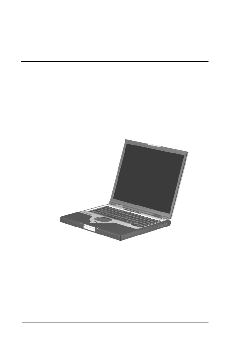
The Compaq Presario 2800 and Evo Notebook N800 Series of
Personal notebooks offer advanced modularity, Intel Mobile
Pentium 4 processors with SpeedStep technology with 64-bit
architecture, industry-leading Accelerated Graphics Port (AGP)
implementation, and extensive multimedia support.
Figure 1-1. Compaq Presario 2800 and Evo Notebook N800
Maintenance and Service Guide 1–1
Page 7

Product Description
1.1 Models
Notebook models are shown in Tables 1-1 through 1-4.
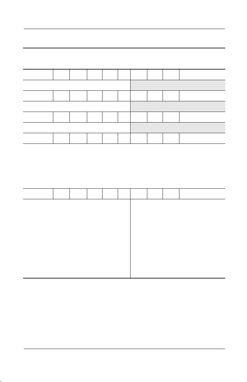
Table 1-1
Compaq Evo Notebook N800c, Evo Notebook N800v,
Evo Notebook 800w, and Presario 2800 Model Naming Conventions
Key
N800w P 220 U5 50 W C 51 O XXXXXX-XXX
123456789 10
Key Description Options
1 Brand/Series
designator
2 Processor type P = Intel Pentium 4
3 Processor speed 220 = 2.2 GHz
4Display type/
size/resolution
5 Hard drive size 50 = 50 GB
6 Optical drive
designator
7 Integrated
communication
8 RAM 51 = 512 MB
9 Operating system 2 = Windows 2000 O = Windows XP Pro
10 SKU#
N = Evo Notebook
P = Presario
200 = 2.0 GHz
190 = 1.9 GHz
180 = 1.8 GHz
U = UXGA (1600 × 1200)
P = SXGA+ (1400 × 1050)
X = XGA (1024 × 768)
40 = 40 GB
D = CD-ROM drive
R = CD-RW drive
V = DVD-ROM drive
M = modem
0 = none
38 = 384 MB
800 = 800 Series
2800 = 2800 Series
170 = 1.7 GHz
160 = 1.6 GHz
150 = 1.5 GHz
140 = 1.4 GHz
30 = 30 GB
20 = 20 GB
W = DVD-RW drive
Z = DVD/CD-RW drive
C = modem/NIC
25 = 256 MB
12 = 128 MB
E = Windows XP Home
5 = 15.x-inch
4 = 14.x-inch
combination card
1–2 Maintenance and Service Guide
Page 8

Product Description
Table 1-2
Compaq Evo Notebook N800c Models
The following Compaq Evo Notebook N800c models use config. code KLMZ
and feature:
■ Dual pointing device (TouchPad and pointing stick)
■ 8-cell, 4.0 Ah lithium ion (Li ion) battery pack
■ 32 MB discrete video memory
■ 3-year warranty on parts, labor, and on-site, next business day response
N800c P 220 P5 40 Z C 25 2
Belgium
Czech Republic
Denmark
European
International
France
Germany
Greece/Poland
Hungary
Israel
Italy
470053-708
470053-709
470053-711
470053-712
470053-713
470053-714
470053-716
470053-717
470053-718
470053-719
The Netherlands
Norway
Portugal
Russia
Saudi Arabia
Slovenia
Spain
Sweden/Finland
Switzerland
Tu r ke y
United Kingdom
N800c P 220 P5 40 Z C 25 O
Belgium
Czech Republic
Denmark
European
International
France
Germany
Greece/Poland
Hungary
Israel
Italy
470052-869
470052-870
470052-875
470052-877
470052-878
470052-879
470052-880
470052-881
470052-882
470052-883
The Netherlands
Norway
Portugal
Russia
Saudi Arabia
Slovenia
Spain
Sweden/Finland
Switzerland
Tu r ke y
United Kingdom
470053-720
470053-721
470053-722
470053-723
470053-707
470053-724
470053-725
470053-726
470053-727
470053-728
470053-729
470052-884
470052-885
470052-886
470052-887
470052-837
470052-888
470052-889
470052-890
470052-891
470052-892
470052-893
Maintenance and Service Guide 1–3
Page 9

Product Description
Table 1-2
Compaq Evo Notebook N800c Models
N800c P 180 P5 30 V C 25 2
(Continued)
Belgium
Czech Republic
Denmark
European
International
France
Germany
Greece/Poland
Hungary
Israel
Italy
N800c P 180 P5 30 V C 25 O
Belgium
Czech Republic
Denmark
European
International
France
Germany
Greece/Poland
Hungary
Israel
Italy
470052-816
470052-817
470052-818
470052-819
470052-820
470052-821
470052-822
470052-823
470052-824
470052-825
470052-755
470052-756
470052-757
470052-758
470052-759
470052-760
470052-761
470052-762
470052-763
470052-764
The Netherlands
Norway
Portugal
Russia
Saudi Arabia
Slovenia
Spain
Sweden/Finland
Switzerland
Tu r ke y
United Kingdom
The Netherlands
Norway
Portugal
Russia
Saudi Arabia
Slovenia
Spain
Sweden/Finland
Switzerland
Tu r ke y
United Kingdom
470052-826
470052-827
470052-828
470052-829
470052-815
470052-830
470052-832
470052-833
470052-834
470052-835
470052-836
470052-765
470052-766
470052-767
470052-768
470052-754
470052-769
470052-770
470052-771
470052-772
470052-773
470052-774
1–4 Maintenance and Service Guide
Page 10
Table 1-2
Compaq Evo Notebook N800c Models
N800c P 180 X5 20 D C 25 2
(Continued)
Product Description
Belgium
Czech Republic
Denmark
European
International
France
Germany
Greece/Poland
Hungary
Israel
Italy
N800c P 180 X5 20 D C 20 O
Belgium
Czech Republic
Denmark
European
International
France
Germany
Greece/Poland
Hungary
Israel
Italy
N800c P 170 P5 30 V C 25 2
United States 470041-454
470052-734
470052-735
470052-736
470052-737
470052-738
470052-739
470052-740
470052-741
470052-742
470052-743
470052-711
470052-712
470052-713
470052-716
470052-717
470052-718
470052-719
470052-720
470052-721
470052-722
The Netherlands
Norway
Portugal
Russia
Saudi Arabia
Slovenia
Spain
Sweden/Finland
Switzerland
Tu r ke y
United Kingdom
The Netherlands
Norway
Portugal
Russia
Saudi Arabia
Slovenia
Spain
Sweden/Finland
Switzerland
Tu r ke y
United Kingdom
470052-744
470052-745
470052-746
470052-747
470052-733
470052-748
470052-749
470052-750
470052-751
470052-752
470052-753
470052-723
470052-724
470052-725
470052-726
470052-710
470052-727
470052-728
470052-729
470052-730
470052-731
470052-732
N800c P 170 P5 30 V C 25 O
United States 470041-455
N800c P 170 P5 30 0 C 0 2
United States 470041-456
N800c P 170 P5 30 0 C 0 O
United States 470041-457
Maintenance and Service Guide 1–5
Page 11

Product Description
Table 1-2
Compaq Evo Notebook N800c Models
The following Compaq Evo Notebook N800c models use config. code KLMZ
and feature:
■ Dual pointing device (TouchPad and pointing stick)
■ 8-cell, 4.0 Ah Li ion battery pack
■ 32 MB discrete video memory
■ 3-year warranty on parts and labor, 2-year warranty on on-site,
next business day response
N800c P 200 P5 30 V C 25 2
Asia Pacific
Australia
Belgium
Brazil
Czech Republic
Denmark
European
International
France
French Canada
Germany
Greece/Poland
Hong Kong
Hungary
India
Israel
Italy
Japan
Korea
Latin America
470049-178
470049-174
470049-142
470049-172
470049-143
470049-144
470049-145
470049-146
470049-139
470049-147
470049-148
470049-182
470049-149
470049-179
470049-150
470049-151
470049-169
470049-183
470049-170
Latin America
(NAFTA)
The Netherlands
Norway
People’s
Republic
of China
Portugal
Russia
Saudi Arabia
Slovenia
Spain
Sweden/Finland
Switzerland
Ta i wa n
Thailand
Tu r ke y
United Kingdom
United States
(Continued)
470049-171
470049-152
470049-154
470049-180
470049-155
470049-157
470049-141
470049-158
470049-159
470049-160
470049-162
470049-181
470049-177
470049-167
470049-168
470049-138
1–6 Maintenance and Service Guide
Page 12

Table 1-2
Compaq Evo Notebook N800c Models
N800c P 200 P5 30 V C 25 O
Asia Pacific
Australia
Belgium
Brazil
Czech Republic
Denmark
European
International
France
French Canada
Germany
Greece/Poland
Hong Kong
Hungary
India
Israel
Italy
Japan
Korea
Latin America
470049-123
470049-117
470049-080
470049-116
470049-081
470049-083
470049-084
470049-085
470049-078
470049-086
470049-087
470049-133
470049-088
470049-125
470049-089
470049-090
470049-109
470049-136
470049-113
Latin America
(NAFTA)
The Netherlands
Norway
People’s
Republic
of China
Portugal
Russia
Saudi Arabia
Slovenia
Spain
Sweden/Finland
Switzerland
Ta i wa n
Thailand
Tu r ke y
United Kingdom
United States
Product Description
(Continued)
470049-115
470049-094
470049-096
470049-129
470049-097
470049-098
470049-079
470049-099
470049-100
470049-101
470049-105
470049-132
470049-120
470049-107
470049-108
470049-077
Maintenance and Service Guide 1–7
Page 13

Product Description
Table 1-2
Compaq Evo Notebook N800c Models
The following Compaq Evo Notebook N800c models use config. code KLMZ
and feature:
■ Dual pointing device (TouchPad and pointing stick)
■ 8-cell, 4.0 Ah Li ion battery pack
■ 32 MB discrete video memory
■ 3-year warranty on parts and labor
N800c P 180 U5 50 W C 51 O
(Continued)
Belgium
Czech Republic
Denmark
European
International
France
Germany
Greece/Poland
Hungary
Israel
Italy
470035-393
470035-396
470035-399
470035-412
470035-416
470035-420
470035-424
470035-427
470035-430
470035-433
The Netherlands
Norway
Portugal
Russia
Saudi Arabia
Slovenia
Spain
Sweden/Finland
Switzerland
Tu r ke y
United Kingdom
N800c P 180 P5 50 W C 51 2
Asia Pacific
Australia
Brazil
French Canada
Hong Kong
Japan
Korea
Latin America
470035-264
470035-259
470035-253
470035-197
470035-280
470035-204
470035-284
470035-209
Latin America
(NAFTA)
People’s
Republic
of China
Ta i wa n
United States
470035-436
470035-440
470035-449
470035-459
470035-373
470035-462
470035-465
470035-468
470035-471
470035-474
470035-477
470035-210
470035-271
470035-274
470035-190
1–8 Maintenance and Service Guide
Page 14

Table 1-2
Compaq Evo Notebook N800c Models
N800c P 180 P5 50 W C 51 O
(Continued)
Product Description
Asia Pacific
Australia
Brazil
French Canada
Hong Kong
Japan
Korea
Latin America
N800c P 170 P5 40 W C 25 2
Asia Pacific
Australia
Brazil
French Canada
Hong Kong
Japan
Korea
Latin America
N800c P 170 P5 40 W C 25 O
Asia Pacific
Australia
Brazil
French Canada
Hong Kong
Japan
Korea
Latin America
470035-307
470035-305
470035-302
470035-293
470035-310
470035-295
470035-319
470035-297
470035-304
470035-301
470035-298
470035-282
470035-315
470035-287
470035-317
470035-290
470035-303
470035-300
470035-296
470035-281
470035-314
470035-285
470035-316
470035-288
Latin America
(NAFTA)
People’s
Republic
of China
Ta i wa n
United States
Latin America
(NAFTA)
People’s
Republic
of China
Ta i wa n
United States
Latin America
(NAFTA)
People’s
Republic
of China
Ta i wa n
United States
470035-299
470035-308
470035-309
470035-289
470035-294
470035-311
470035-313
470035-278
470035-292
470035-306
470035-312
470035-276
Maintenance and Service Guide 1–9
Page 15

Product Description
Table 1-2
Compaq Evo Notebook N800c Models
N800c P 170 X5 30 V C 25 2
Asia Pacific
Australia
Belgium
Brazil
Czech Republic
Denmark
European
International
France
French Canada
Germany
Greece/Poland
Hong Kong
Hungary
Israel
Italy
Japan
Korea
Latin America
470035-260
470035-258
470035-228
470035-256
470035-229
470035-230
470035-231
470035-232
470035-226
470035-233
470035-234
470035-266
470035-235
470035-236
470035-237
470035-250
470035-268
470035-252
Latin America
(NAFTA)
The Netherlands
Norway
People’s
Republic
of China
Portugal
Russia
Saudi Arabia
Slovenia
Spain
Sweden/Finland
Switzerland
Ta i wa n
Tu r ke y
United Kingdom
United States
(Continued)
470035-254
470035-238
470035-239
470035-262
470035-240
470035-241
470035-227
470035-243
470035-244
470035-245
470035-247
470035-265
470035-248
470035-249
470035-225
1–10 Maintenance and Service Guide
Page 16

Table 1-2
Compaq Evo Notebook N800c Models
N800c P 170 X5 30 V C 25 O
Asia Pacific
Australia
Belgium
Brazil
Czech Republic
Denmark
European
International
France
French Canada
Germany
Greece/Poland
Hong Kong
Hungary
Israel
Italy
Japan
Korea
Latin America
470035-033
470035-031
470035-008
470035-030
470035-009
470035-010
470035-011
470035-012
470035-006
470035-013
470035-014
470035-038
470035-015
470035-016
470035-017
470035-028
470035-040
470035-029
Latin America
(NAFTA)
The Netherlands
Norway
People’s
Republic
of China
Portugal
Russia
Saudi Arabia
Slovenia
Spain
Sweden/Finland
Switzerland
Ta i wa n
Tu r ke y
United Kingdom
United States
Product Description
(Continued)
470035-048
470035-018
470035-019
470035-035
470035-020
470035-021
470035-007
470035-022
470035-023
470035-024
470035-025
470035-036
470035-026
470035-027
470035-005
N800c P 160 X5 20 V C 25 2
Asia Pacific
Australia
Brazil
French Canada
Hong Kong
Japan
Korea
Latin America
470035-203
470035-201
470035-199
470035-192
470035-211
470035-193
470035-212
470035-194
Latin America
(NAFTA)
People’s
Republic
of China
Ta i wa n
United States
470035-196
470035-206
470035-208
470035-191
Maintenance and Service Guide 1–11
Page 17

Product Description
Table 1-2
Compaq Evo Notebook N800c Models
N800c P 160 X5 20 V C 25 O
(Continued)
Asia Pacific
Australia
Brazil
French Canada
Hong Kong
Japan
Korea
Latin America
N800c P 160 X5 20 D C 25 2
Belgium
Czech Republic
Denmark
European
International
France
Germany
Greece/Poland
Hungary
Israel
Italy
N800c P 160 X5 20 D C 25 O
Belgium
Czech Republic
Denmark
European
International
France
Germany
Greece/Poland
Hungary
Israel
Italy
470035-220
470035-219
470035-218
470035-214
470035-223
470035-215
470035-224
470035-216
470035-375
470035-394
470035-397
470035-410
470035-413
470035-417
470035-422
470035-425
470035-428
470035-431
470035-377
470035-395
470035-398
470035-411
470035-415
470035-418
470035-423
470035-426
470035-429
470035-432
Latin America
(NAFTA)
People’s
Republic
of China
Ta i wa n
United States
The Netherlands
Norway
Portugal
Russia
Saudi Arabia
Slovenia
Spain
Sweden/Finland
Switzerland
Tu r ke y
United Kingdom
The Netherlands
Norway
Portugal
Russia
Saudi Arabia
Slovenia
Spain
Sweden/Finland
Switzerland
Tu r ke y
United Kingdom
470035-217
470035-221
470035-222
470035-213
470035-434
470035-437
470035-447
470035-457
470035-369
470035-460
470035-463
470035-466
470035-469
470035-472
470035-475
470035-435
470035-439
470035-448
470035-458
470035-370
470035-461
470035-464
470035-467
470035-470
470035-473
470035-476
1–12 Maintenance and Service Guide
Page 18

Product Description
Table 1-3
Compaq Evo Notebook N800v Models
The following Compaq Evo Notebook N800v models use config. code KSQZ
and feature:
■ TouchPad pointing device
■ 8-cell, 4.4 Ah Li ion battery pack
■ 64 MB of discrete video memory
■ 1-year warranty on parts and labor
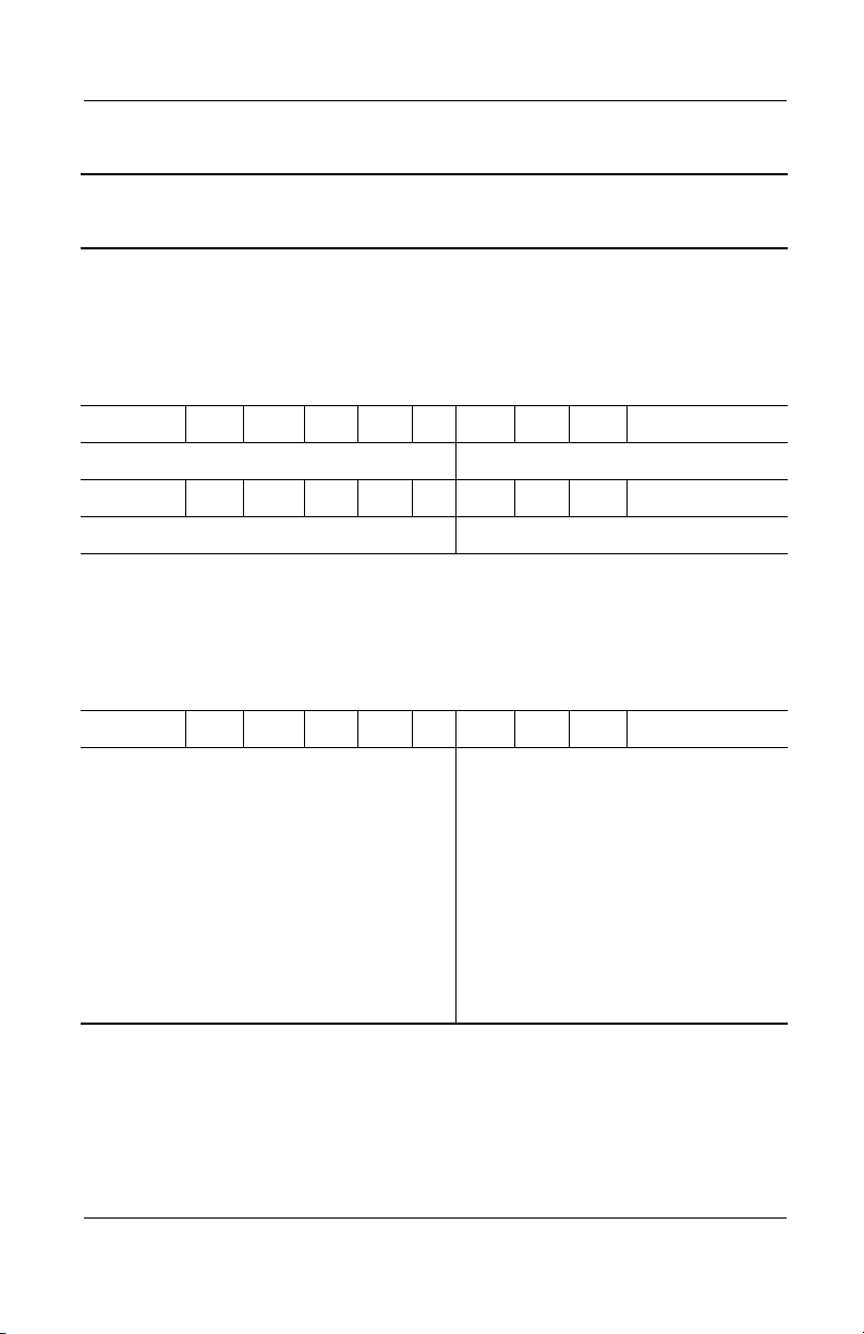
N800v P 200 P5 40 W C 25 O
French Canada 470044-432 United States 470044-406
The following Compaq Evo Notebook N800v models use config. code KSQZ
and feature:
■ TouchPad
■ 8-cell, 4.4 Ah Li ion battery pack
■ 32 MB of discrete video memory
■ 1-year warranty on parts and labor
N800v P 200 P5 40 W C 25 2
Belgium
Czech Republic
Denmark
European
International
France
Greece/Poland
Hungary
Israel
Italy
The Netherlands
470053-885
470053-886
470053-888
470053-889
470053-890
470053-892
470053-893
470053-894
470053-895
470053-896
Norway
Portugal
Russia
Saudi Arabia
Slovenia
Spain
Sweden/Finland
Switzerland
Tu r ke y
United Kingdom
470053-898
470053-899
470053-901
470053-884
470053-902
470053-903
470053-904
470053-905
470053-906
470053-907
Maintenance and Service Guide 1–13
Page 19

Product Description
Table 1-3
Compaq Evo Notebook N800v Models
N800v P 200 P5 40 W C 25 O
(Continued)
Belgium
Czech Republic
Denmark
European
International
France
Greece/Poland
Hungary
Israel
Italy
The Netherlands
N800v P 180 P5 40 W C 25 2
Belgium
Czech Republic
Denmark
European
International
France
Greece/Poland
Hungary
Israel
Italy
The Netherlands
470053-858
470053-859
470053-860
470053-861
470053-866
470053-867
470053-868
470053-869
470053-871
470053-873
470053-770
470053-771
470053-772
470053-775
470053-776
470053-779
470053-780
470053-781
470053-786
470053-787
Norway
Portugal
Russia
Saudi Arabia
Slovenia
Spain
Sweden/Finland
Switzerland
Tu r ke y
United Kingdom
Norway
Portugal
Russia
Saudi Arabia
Slovenia
Spain
Sweden/Finland
Switzerland
Tu r ke y
United Kingdom
470056-874
470053-875
470053-876
470053-877
470053-857
470053-878
470053-879
470053-880
470053-881
470053-882
470053-788
470053-789
470053-790
470053-769
470053-791
470053-795
470053-796
470053-797
470053-798
470053-800
1–14 Maintenance and Service Guide
Page 20

Table 1-3
Compaq Evo Notebook N800v Models
N800v P 180 P5 40 W C 25 O
(Continued)
Product Description
Belgium
Czech Republic
Denmark
European
International
France
Greece/Poland
Hungary
Israel
Italy
The Netherlands
N800v P 180 X5 30 V C 25 2
Belgium
Czech Republic
Denmark
European
International
France
Greece/Poland
Hungary
Israel
Italy
The Netherlands
470053-739
470053-740
470053-746
470053-747
470053-748
470053-749
470053-750
470053-751
470053-752
470053-753
470059-654
470059-655
470059-656
470059-657
470059-658
470059-659
470059-660
470059-661
470059-662
470059-664
Norway
Portugal
Russia
Saudi Arabia
Slovenia
Spain
Sweden/Finland
Switzerland
Tu r ke y
United Kingdom
Norway
Portugal
Russia
Saudi Arabia
Slovenia
Spain
Sweden/Finland
Switzerland
Tu r ke y
United Kingdom
470053-754
470053-755
470053-756
470053-738
470053-757
470053-758
470053-759
470053-760
470053-765
470053-766
470059-665
470059-666
470059-667
470059-653
470059-668
470059-669
470059-670
470059-671
470059-673
470059-674
Maintenance and Service Guide 1–15
Page 21

Product Description
Table 1-3
Compaq Evo Notebook N800v Models
N800v P 180 X4 30 V C 25 2
(Continued)
Belgium
Czech Republic
Denmark
European
International
France
Greece/Poland
Hungary
Israel
Italy
The Netherlands
N800v P 180 X4 30 V C 25 O
Belgium
Czech Republic
Denmark
European
International
France
Greece/Poland
Hungary
Israel
Italy
The Netherlands
470053-831
470053-836
470053-838
470053-839
470053-841
470053-842
470053-843
470053-844
470053-845
470053-846
470053-804
470053-806
470053-808
470053-809
470053-810
470053-811
470053-812
470053-813
470053-814
470053-815
Norway
Portugal
Russia
Saudi Arabia
Slovenia
Spain
Sweden/Finland
Switzerland
Tu r ke y
United Kingdom
Norway
Portugal
Russia
Saudi Arabia
Slovenia
Spain
Sweden/Finland
Switzerland
Tu r ke y
United Kingdom
470053-847
470053-848
470053-849
470053-850
470053-830
470053-851
470053-852
470053-853
470053-854
470053-855
470053-816
470053-817
470053-818
470053-803
470053-819
470053-820
470053-821
470053-822
470053-823
470053-827
1–16 Maintenance and Service Guide
Page 22
Table 1-3
Compaq Evo Notebook N800v Models
N800v P 170 P5 40 W C 25 2
(Continued)
Product Description
Belgium
Czech Republic
Denmark
European
International
France
Greece/Poland
Hungary
Israel
Italy
The Netherlands
N800v P 170 P5 40 W C 25 O
Belgium
Czech Republic
Denmark
European
International
France
Greece/Poland
Hungary
Israel
Italy
The Netherlands
470044-531
470044-532
470044-533
470044-534
470044-535
470044-536
470044-537
470044-538
470044-539
470044-540
470044-486
470044-488
470044-496
470044-501
470044-503
470044-505
470044-506
470044-507
470044-508
470044-511
Norway
Portugal
Russia
Saudi Arabia
Slovenia
Spain
Sweden
Switzerland
Tu r ke y
United Kingdom
Norway
Portugal
Russia
Saudi Arabia
Slovenia
Spain
Sweden
Switzerland
Tu r ke y
United Kingdom
470044-541
470044-542
470044-543
470044-530
470044-544
470044-545
470044-546
470044-547
470044-548
470044-549
470044-512
470044-514
470044-516
470044-483
470044-518
470044-520
470044-521
470044-523
470044-526
470044-527
Maintenance and Service Guide 1–17
Page 23
Product Description
Table 1-3
Compaq Evo Notebook N800v Models
N800v P 170 X4 30 V C 25 2
(Continued)
Belgium
Czech Republic
Denmark
European
International
France
Greece/Poland
Hungary
Israel
Italy
The Netherlands
N800v P 170 X4 30 V C 25 O
Belgium
Czech Republic
Denmark
European
International
France
French Canada
Greece/Poland
Hungary
Israel
Italy
The Netherlands
470044-710
470044-711
470044-712
470044-713
470044-714
470044-715
470044-716
470044-717
470044-718
470044-719
470044-551
470044-552
470044-553
470044-554
470044-555
470035-200
470044-556
470044-557
470044-558
470044-559
470044-560
Norway
Portugal
Russia
Saudi Arabia
Slovenia
Spain
Sweden
Switzerland
Tu r ke y
United Kingdom
Norway
Portugal
Russia
Saudi Arabia
Slovenia
Spain
Sweden
Switzerland
Tu r ke y
United Kingdom
United States
470044-720
470044-721
470044-722
470044-707
470044-723
470044-724
470044-725
470044-726
470044-727
470044-728
470044-561
470044-562
470044-563
470044-550
470044-564
470044-565
470044-566
470044-567
470044-568
470044-569
470035-202
1–18 Maintenance and Service Guide
Page 24

Table 1-3
Compaq Evo Notebook N800v Models
N800v P 160 P5 30 W C 25 O
(Continued)
Product Description
Belgium
Czech Republic
Denmark
European
International
France
Greece/Poland
Hungary
Israel
Italy
The Netherlands
N800v P 160 X4 20 V C 25 O
Belgium
Czech Republic
Denmark
European
International
France
French Canada
Greece/Poland
Hungary
Israel
Italy
The Netherlands
470035-759
470035-760
470035-763
470035-768
470035-770
470035-771
470035-773
470035-774
470035-776
470035-778
470035-207
470035-242
470035-246
470034-251
470035-255
470035-198
470035-257
470035-261
470035-263
470035-267
470035-269
Norway
Portugal
Russia
Saudi Arabia
Slovakia
Spain
Sweden/Finland
Switzerland
Tu r ke y
United Kingdom
Norway
Portugal
Russia
Saudi Arabia
Slovenia
Spain
Sweden/Finland
Switzerland
Tu r ke y
United Kingdom
United States
470035-779
470035-781
470035-782
470035-757
470035-784
470035-785
470035-787
470035-788
470035-790
470035-791
470035-270
470035-272
470035-273
470035-205
470035-275
470035-277
470035-279
470035-283
470035-286
470035-703
470035-195
Maintenance and Service Guide 1–19
Page 25

Product Description
Table 1-3
Compaq Evo Notebook N800v Models
The following Compaq Evo Notebook N800v models use config. code KSRZ
and feature:
■ TouchPad
■ 8-cell, 4.4 Ah Li ion battery pack
■ 32 MB of discrete video memory
■ 2-year warranty on parts and labor
N800v P 200 P5 40 W C 51 2
Germany 470053-908
N800v P 200 P5 40 W C 51 O
Germany 470053-883
N800v P 180 P5 40 W C 51 2
Germany 470053-801
N800v P 180 P5 40 W C 25 O
Germany 470053-767
N800v P 180 X4 30 V C 25 2
Germany 470053-856
(Continued)
N800v P 180 X4 30 V C 25 O
Germany 470053-829
N800v P 170 P5 40 W C 25 2
Germany 470045-606
N800v P 170 P5 40 W C 25 O
Germany 470045-605
1–20 Maintenance and Service Guide
Page 26
Product Description
Table 1-3
Compaq Evo Notebook N800v Models
N800v P 170 X4 30 V C 25 2
Germany 470045-608
N800v P 170 X4 30 V C 25 O
Germany 470045-607
N800v P 160 X4 20 V C 25 O
Germany 470035-291
N800v P 180 X5 30 V C 25 O
The following Compaq Evo Notebook N800v models use config. code LLYZ
and feature:
■ TouchPad
■ 8-cell, 4.4 Ah Li ion battery pack
■ 32 MB of discrete video memory
■ 1-year warranty on parts and labor
N800v P 180 X5 30 V C 25 O
(Continued)
Belgium
Czech Republic
Denmark
European
International
France
Greece/Poland
Hungary
Israel
Italy
The Netherlands
470059-634
470059-635
470059-636
470059-637
470059-638
470059-639
470059-640
470059-641
470059-642
470059-643
Norway
Portugal
Russia
Saudi Arabia
Slovenia
Spain
Sweden/Finland
Switzerland
Tu r ke y
United Kingdom
470059-644
470059-645
470059-646
470059-633
470059-647
470059-648
470059-649
470059-650
470059-651
470059-652
Maintenance and Service Guide 1–21
Page 27
Product Description
Table 1-4
Compaq Evo Notebook N800w Models
The following Compaq Evo Notebook N800w models use config. code LDF1
and feature:
■ Dual pointing device (TouchPad and pointing stick)
■ 8-cell, 4.4 Ah Li ion battery pack
■ 64 MB of discrete video memory
■ 3-year warranty on parts, labor, and on-site, next business day response
N800w P 220 U5 50 W C 51 2
French Canada 470043-588 United States 470043-584
N800w P 220 U5 50 W C 51 O
French Canada 470043-575 United States 470043-574
The following Compaq Evo Notebook N800w models use config. code LDFZ
and feature:
■ Dual pointing device (TouchPad and pointing stick)
■ 8-cell, 4.4 Ah Li ion battery pack
■ 64 MB of discrete video memory
■ 3-year warranty on parts and labor
N800w P 220 U5 50 W C 51 2
Asia Pacific
Australia
Belgium
European
International
France
Germany
Hong Kong
Italy
Japan
Korea
470043-608
470043-606
470043-592
470047-493
470043-596
470043-597
470043-611
470043-598
470051-459
470043-612
Latin America
The Netherlands
People’s
Republic
of China
Spain
Sweden/Finland
Switzerland
Ta i wa n
United Kingdom
470043-605
470043-599
470043-609
470043-600
470051-457
470043-602
470043-610
470043-604
1–22 Maintenance and Service Guide
Page 28
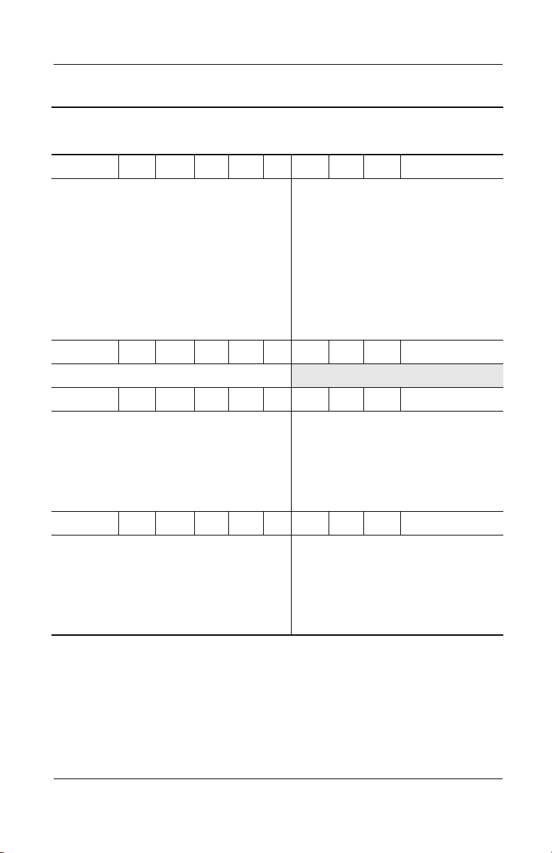
Table 1-4
Compaq Evo Notebook N800w Models
N800w P 220 U5 50 W C 51 O
(Continued)
Product Description
Asia Pacific
Australia
Belgium
European
International
France
Germany
Hong Kong
Italy
Korea
N800
w P 200 P5 50 D C 51 2
Japan 470051-463
N800w P 200 P5 40 W C 25 2
Belgium
European
International
France
Germany
Italy
N800w P 200 P5 40 W C 25 O
Belgium
European
International
France
Germany
Italy
470043-590
470043-589
470043-576
470047-495
470043-578
470043-579
470043-594
470043-580
470043-595
470043-614
470047-496
470043-615
470043-616
470043-617
470043-623
470047-497
470043-624
470043-625
470043-626
Latin America
The Netherlands
People’s
Republic
of China
Sweden/Finland
Spain
Switzerland
Ta i wa n
United Kingdom
The Netherlands
Spain
Sweden/Finland
Switzerland
United Kingdom
The Netherlands
Spain
Sweden/Finland
Switzerland
United Kingdom
470043-587
470043-581
470043-591
470051-460
470043-583
470043-585
470043-593
470043-586
470043-618
470043-619
470051-461
470043-620
470043-621
470043-633
470043-634
470051-462
470043-635
470043-636
Maintenance and Service Guide 1–23
Page 29
Product Description
Table 1-4
Compaq Evo Notebook N800w Models
The following Compaq Evo Notebook N800w model uses config. code LMBZ
and features:
■ Dual pointing device (TouchPad and pointing stick)
■ 8-cell, 4.4 Ah Li ion battery pack
■ 64 MB of discrete video memory
■ 3-year warranty on parts, labor, and on-site, next business day response
N800w P 220 U5 50 W C 51 O
French Canada 470052-422 United States 470052-361
N800w P 220 U5 50 W C 51 2
French Canada 470052-421 United States 470052-128
The following Compaq Evo Notebook N800w model uses config. code LMBZ
and features:
■ Dual pointing device (TouchPad and pointing stick)
■ 8-cell, 4.4 Ah Li ion battery pack
■ 64 MB of discrete video memory
■ 3-year warranty on parts and labor
(Continued)
N800W P 200 P5 40 W C 25 2
Norway 470060-060
N800W P 200 P5 40 W C 25 O
Norway 470060-061
1–24 Maintenance and Service Guide
Page 30

Product Description
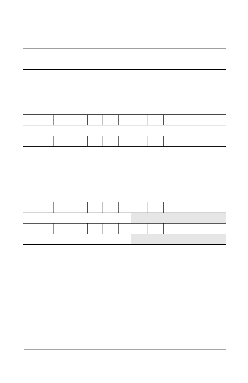
Table 1-5
Compaq Presario 2800 Models
The following Compaq Presario 2800 models use config. code KSQZ and
feature:
■ Diskette drive
■ TouchPad
■ 8-cell, 4.4 Ah Li ion battery pack
■ 64 MB of discrete video memory
■ 1-year warranty on parts and labor
N800w P 220 U5 50 W C 51 2
Asia Pacific
Australia
Belgium
Denmark
European
470052-392
470052-390
470052-362
470052-363
470052-364
Latin America
The Netherlands
Norway
People’s
International
France
Germany
Hong Kong
Italy
Japan
Korea
N800
w P 220 U5 50 W C 51 O
Asia Pacific
Australia
Belgium
Denmark
European
470052-365
470052-366
470052-397
470052-367
470052-401
470052-399
470052-416
470052-415
470052-402
470052-403
470052-404
Spain
Sweden/Finland
Switzerland
Ta i wa n
United Kingdom
Latin America
The Netherlands
Norway
People’s
International
France
Germany
Hong Kong
Italy
Japan
Korea
470052-405
470052-406
470052-419
470052-408
470059-058
470052-420
Spain
Sweden/Finland
Switzerland
Ta i wa n
United Kingdom
470052-388
470052-368
470060-058
470052-393
Republic
of China
470052-369
470052-375
470052-385
470052-396
470052-387
470052-414
470052-409
470060-059
470052-417
Republic
of China
470052-410
470052-411
470052-412
470052-418
470052-413
Maintenance and Service Guide 1–25
Page 31

Product Description
Table 1-5
Compaq Presario 2800 Models
P2838 P 220 P5 50 W C 25 E
Taiwan 470048-547
P2868 P 220 P5 40 Z C 25 E
Korea 470057-643
P2832 P 220 P5 40 W C 51 E
Hong Kong 470048-542
P2838 P 220 X5 40 W C 51 E
Asia Pacific 470047-539 Australia 470047-533
P2844 P 220 X4 40 W C 25 E
Asia Pacific 470050-912
P2830 P 200 U5 50 W C 51 E
Asia Pacific 470045-996 Australia 470045-995
P2867 P 200 P5 40 Z C 25 E
(Continued)
Korea 470057-642
P2822 P 200 P5 40 W C 51 E
Hong Kong 470044-692
P2827 P 200 P5 40 W C 25 E
Taiwan 470044-697
P2837 P 200 P5 40 V C 25 E
Taiwan 470048-546
P2845 P 200 X5 40 W C 51 E
Korea 470051-466 Thailand 470051-465
P2837 P 200 X5 40 W C 25 E
Asia Pacific
India
470047-516
470050-915
Korea
Thailand
470048-533
470047-515
1–26 Maintenance and Service Guide
Page 32

Table 1-5
Compaq Presario 2800 Models
P2871 P 200 X5 30 V C 25 E
Hong Kong 470057-646
P2831 P 200 X5 40 V C 25 E
(Continued)
Product Description
People’s Republic
of China
P2840 P 200 X4 40 W C 51 E
Hong Kong 470050-910
P2866 P 200 X4 30 Z C 25 E
Korea 470057-641
P2820 P 190 U5 40 W C 51 E
Asia Pacific
Korea
P2840 P 190 P5 40 W C 51 E
Korea 470048-534
P2825 P 190 P5 40 W C 51 E
European
International
France
Greece/Poland
P2820 P 190 P5 40 W C 25 E
Korea 470044-683
P2826 P 190 P5 30 W C 25 E
470047-505
470044-580
470044-581
470044-575
470045-992
470045-993
Thailand 470044-579
Saudi Arabia
Switzerland
Tu r ke y
470044-574
470046-565
470046-566
Taiwan 470044-696
2830 P 190 X5 40 V C 25 E
People’s Republic
of China
470047-504
Maintenance and Service Guide 1–27
Page 33

Product Description
Table 1-5
Compaq Presario 2800 Models
2836 P 190 X5 30 W C 25 E
(Continued)
Asia Pacific
India
P2870 P 190 X5 30 V C 25 E
Hong Kong 470057-645
P2869 P 190 X5 30 D C 25 E
Hong Kong 470057-644
P2820 P 190 X4 40 W C 25 E
People’s Republic
of China
P2865 P 190 X4 30 V C 25 E
Korea 470057-640
P2832 P 190 X4 30 V C 25 E
People’s Republic
of China
P2864 P 190 X4 30 D C 25 E
Korea 470057-639
P2820 P 180 U5 40 W C 51 E
Asia Pacific
Korea
470047-512
470048-514
470044-698
470051-464
470036-651
470037-983
Thailand 470047-513
Thailand 470037-984
P2828 P 180 P5 40 W C 51 E
Korea 470044-630
P2821 P 180 P5 40 W C 51 E
Hong Kong 470038-884
P2821 P 180 P5 40 W C 51 E
Australia 470044-686
1–28 Maintenance and Service Guide
Page 34

Table 1-5
Compaq Presario 2800 Models
P2810 P 180 P5 40 W C 51 E
(Continued)
Product Description
People’s Republic
of China
P2830 P 180 P5 40 W C 25 E
Australia 470047-518
P2823 P 180 P5 40 W C 25 E
India 470044-625
P2815 P 180 P5 40 W C 25 E
Australia 470037-986
P2820 P 180 P5 40 R C 25 E
Taiwan 470036-661
P2822 P 180 X5 40 W C 25 E
France 470046-890
P2863 P 180 X5 40 D C 25 E
Korea 470057-638
P2831 P 180 X4 40 W C 25 E
Hong Kong 470048-541
P2835 P 180 X4 30 W C 25 E
Asia Pacific
Hong Kong
470037-116
470047-511
470048-532
Thailand 470047-509
P2821 P 180 X4 30 W C 25 E
Hong Kong 470044-691
P2821 P 180 X4 30 V C 25 E
People’s Republic
of China
470044-699
Maintenance and Service Guide 1–29
Page 35

Product Description
Table 1-5
Compaq Presario 2800 Models
P2814 P 170 P5 40 W C 51 E
Australia 470036-653 Korea 470037-985
P2816 P 170 P5 30 W C 51 E
(Continued)
European
International
France
Greece/Poland
Hungary
Israel
P2808 P 170 P5 30 W C 51 O
European
International
P2817 P 170 P5 30 V C 25 E
Taiwan 470036-660
P2818 P 170 X5 40 W C 25 E
France 470040-192
P2806 P 170 X4 40 V C 25 E
People’s Republic
of China
P2816 P 170 X4 30 W C 25 E
Taiwan 470037-123
P2818 P 160 P5 40 W C 25 E
India 470036-647
470034-897
470034-898
470034-900
470034-902
470034-904
470036-402
470036-655
Russia
Saudi Arabia
Switzerland
Tu r ke y
United Kingdom
470034-910
470034-893
470034-962
470034-924
470034-925
P2817 P 160 X4 40 W C 25 E
Hong Kong 470037-371
P2819 P 160 X4 30 V C 25 E
Hong Kong 470037-372
1–30 Maintenance and Service Guide
Page 36

Table 1-5
Compaq Presario 2800 Models
P2804 P 160 X4 30 V C 25 E
(Continued)
Product Description
People’s Republic
470036-654
of China
The following Compaq Presario 2800 models use config. code KSQZ and
feature:
■ Diskette drive
■ TouchPad
■ 8-cell, 4.4 Ah Li ion battery pack
■ 32 MB of discrete video memory
■ 1-year warranty on parts and labor
P2820 P 200 X5 40 W C 51 E
United States 470045-990
P2836 P 200 X4 40 V C 25 E
Taiwan 470048-545
P2839 P 190 X4 40 V C 25 E
Taiwan 470050-109
P2811 P 180 X5 40 W C 51 E
United States 470037-370
P2841 P 180 X5 30 W C 25 E
Korea 470048-535
P2821 P 180 X5 30 W C 25 E
Asia Pacific 470044-583 Thailand 470044-582
P2820 P 180 X5 30 W C 25 E
European
International
Greece/Poland
Hungary
Israel
470044-571
470044-572
470047-875
470044-573
Russia
Saudi Arabia
Switzerland
Tu r ke y
470046-887
470044-570
470052-338
470046-562
Maintenance and Service Guide 1–31
Page 37

Product Description
Table 1-5
Compaq Presario 2800 Models
P2821 P 180 X5 30 W C 25 O
(Continued)
European
International
P2834 P 180 X4 40 V C 25 E
Taiwan 470048-544
2843 P 180 X4 30 V C 25 E
Hong Kong 470048-538 Korea 470048-539
P2825 P 180 X4 30 V C 25 E
Taiwan 470044-695
2839 P 180 X4 30 V C 12 E
Asia Pacific 470052-501 India 470047-520
P2830 P 180 X4 30 D C 25 E
Korea 470048-540
P2833 P 180 X4 20 V C 25 E
Taiwan 470048-543
P2825 P 170 X5 30 W C 25 E
Korea 470044-627
P2819 P 170 X5 30 W C 25 E
Asia Pacific 470037-119 Thailand 470037-988
470047-498
P2824 P 170 X5 30 V C 12 E
India 470044-626
P2826 P 170 X5 30 R C 25 E
Korea 470044-628
P2820 P 170 X5 20 W C 25 E
United States 470052-500
1–32 Maintenance and Service Guide
Page 38

Product Description
Table 1-5
Compaq Presario 2800 Models
P2827 P 170 X5 20 V C 25 E
Korea 470044-629
P2830 P 170 X4 30 W C 25 E
Saudi Arabia 470044-576 Turkey 470046-569
P2828 P 170 X4 30 W C 25 E
Hong Kong 470045-997
P2837 P 170 X4 30 W C 25 O
Turkey 470048-188
P2835 P 170 X4 30 V C 25 E
European
International
P2832 P 170 X4 30 V C 25 E
Korea 470046-895
470044-578 Saudi Arabia 470044-577
(Continued)
P2829 P 170 X4 30 V C 25 E
Taiwan 470046-901
P2820 P 170 X4 30 V C 25 E
Hong Kong 470044-690
P2831 P 170 X4 30 D C 25 E
Korea 470046-897
P2822 P 170 X4 20 W C 25 E
Asia Pacific 470044-624 Thailand 470044-623
P2820 P 170 X4 20 W C 25 E
United States 470052-499
P2824 P 170 X4 20 V C 25 E
Taiwan 470044-694
Maintenance and Service Guide 1–33
Page 39

Product Description
Table 1-5
Compaq Presario 2800 Models
P2823 P 170 X4 20 R C 25 E
Australia 470044-688
P2829 P 170 X4 20 D C 25 E
Korea 470044-631
P2823 P 170 X4 20 D C 25 E
Taiwan 470044-693
P2810 P 160 P5 40 W C 51 E
Asia Pacific 470033-264 Korea 470033-266
P2802 P 160 P5 40 W C 51 E
People’s Republic
of China
P2810 P 160 P5 40 R C 25 E
Hong Kong 470033-190 Taiwan 470033-186
470033-179
(Continued)
P2818 P 160 X5 30 W C 25 E
Korea 470037-982
P2811 P 160 X5 30 W C 25 E
European
International
France
Greece/Poland
Hungary
Israel
P2806 P 160 X5 30 W C 25 O
European
International
P2816 P 160 X5 30 V C 12 E
India 470036-646
470034-949
470034-950
470034-951
470034-952
470034-953
470036-400
Russia
Saudi Arabia
Switzerland
Tu r ke y
United Kingdom
470034-955
470034-947
470034-958
470034-959
470034-960
1–34 Maintenance and Service Guide
Page 40

Product Description
Table 1-5
Compaq Presario 2800 Models
P2817 P 160 X5 30 R C 25 E
Korea 470037-980
P2811 P 160 X5 20 W C 25 E
Switzerland 470037-978
P2816 P 160 X5 20 V C 25 E
Korea 470037-979
P2817 P 160 X4 30 W C 25 E
France 470040-689
P2813 P 160 X4 30 W C 25 E
Hong Kong 470038-960
P2815 P 160 X4 30 V C 25 E
Hong Kong 470041-601 Taiwan 470036-659
P2813 P 160 X4 30 R C 25 E
(Continued)
Australia 470036-652
P2817 P 160 X4 20 W C 25 E
Saudi Arabia 470038-963
P2814 P 160 X4 20 W C 25 E
Asia Pacific 470037-987 Thailand 470036-656
P2801 P 160 X4 20 W C 25 E
Turkey 470043-744
P2801 P 160 X4 20 V C 25 E
European
International
France
Greece/Poland
Hungary
Israel
470034-911
470034-912
470034-913
470034-915
470034-916
Russia
Saudi Arabia
Switzerland
Tu r ke y
United Kingdom
470034-919
470034-903
470034-961
470034-922
470034-923
Maintenance and Service Guide 1–35
Page 41

Product Description
Table 1-5
Compaq Presario 2800 Models
P2804 P 160 X4 20 V C 25 O
(Continued)
European
International
P2812 P 160 X4 20 R C 25 E
Australia 470040-833
P2815 P 160 X4 20 D C 25 E
Asia Pacific 470041-560 Korea 470036-648
P2812 P 160 X4 20 D C 25 E
Taiwan 470036-658
P2810 P 150 P5 40 W C 51 E
Australia 470033-262
P2809 P 150 P5 40 W C 25 E
India 470033-265
P2815 P 150 P5 30 W C 51 E
Czech Republic
European
International
France
Greece/Poland
Hungary
Israel
Portugal
470036-398
470033-225
470033-226
470033-227
470033-228
470033-229
470033-232
470033-233
Russia
Saudi Arabia
Slovenia
Spain
Switzerland
Tu r ke y
United Kingdom
470033-239
470033-222
470033-240
470033-241
470033-242
470033-244
470033-245
P2805 P 150 P5 30 W C 25 E
Hong Kong 470033-191 Taiwan 470033-185
P2803 P 150 P5 30 W C 25 E
Hong Kong 470033-199 Taiwan 470033-183
P2807 P 150 X5 30 W C 25 E
Asia Pacific 470033-170 Korea 470033-173
1–36 Maintenance and Service Guide
Page 42

Product Description
Table 1-5
Compaq Presario 2800 Models
P2804 P 150 X5 30 V C 25 E
Hong Kong 470033-198 Taiwan 470033-184
P2806 P 150 X5 30 R C 25 E
Asia Pacific 470033-176 Korea 470033-174
P2801 P 150 X4 40 V C 25 E
People’s Republic
of China
P2802 P 150 X4 30 V C 25 E
Hong Kong 470033-200 Taiwan 470033-182
P2805 P 150 X4 30 R C 25 E
Australia 470033-267
P2812 P 140 X5 30 W C 25 E
Sweden/Finland 470035-708
470033-178
(Continued)
P2810 P 140 X5 30 W C 25 E
Czech Republic
European
International
France
Greece/Poland
Hungary
Israel
Portugal
P2804 P 140 X5 30 V C 25 E
India 470033-269
470033-192
470033-193
470033-194
470033-195
470033-196
470033-207
470033-208
Russia
Saudi Arabia
Slovenia
Spain
Switzerland
Tu r ke y
United Kingdom
470033-209
470033-189
470033-210
470033-211
470033-212
470033-213
470033-214
Maintenance and Service Guide 1–37
Page 43

Product Description
Table 1-5
Compaq Presario 2800 Models
P2805 P 140 X5 20 W C 25 E
(Continued)
Czech Republic
European
International
France
Greece/Poland
Hungary
Israel
Portugal
P2805 P 140 X5 20 V C 25 E
Asia Pacific 470033-268 Korea 470033-270
P2812 P 140 X4 40 W C 25 E
Asia Pacific 470035-188
P2811 P 140 X4 30 V C 25 E
Asia Pacific 470035-189
P2801 P 140 X4 30 V C 25 E
Hong Kong 470033-205 Taiwan 470033-181
P2800 P 140 X4 30 V C 25 E
People’s Republic
of China
P2801 P 140 X4 30 V C 12 E
India 470033-259
470033-135
470033-136
470033-137
470033-138
470033-139
470033-140
470033-141
470033-177
Russia
Saudi Arabia
Slovenia
Spain
Switzerland
Tu r ke y
United Kingdom
470033-143
470033-133
470033-144
470033-145
470033-146
470033-147
470033-148
1–38 Maintenance and Service Guide
Page 44

Table 1-5
Compaq Presario 2800 Models
P2810 P 140 X4 20 W C 25 E
(Continued)
Product Description
Latin America 47033-256 Latin America
(NAFTA)
P2802 P 140 X4 20 W C 25 E
Spain 470035-707
P2800 P 140 X4 20 V C 25 E
Czech Republic
European
International
France
Greece/Poland
Hungary
Israel
Portugal
P2800 P 140 X4 20 D C 25 E
Asian Pacific
Hong Kong
P2800 P 140 X4 20 R C 25 E
Australia 470033-168
470033-111
470033-112
470033-113
470033-114
470033-115
470033-116
470033-117
470033-258
470033-206
Russia
Saudi Arabia
Slovenia
Spain
Switzerland
Tu r ke y
United Kingdom
Korea
Ta i wa n
470034-524
470033-118
470033-110
470033-119
470033-120
470033-121
470033-122
470033-123
470033-261
470033-180
and
470033-260
Maintenance and Service Guide 1–39
Page 45

Product Description
Table 1-5
Compaq Presario 2800 Models
The following Compaq Presario 2800 models are available in the United States
and feature:
■ TouchPad pointing device
■ 8-cell, 4.0 Ah Li ion battery pack
■ 32 MB discrete video memory
■ 1-year warranty on parts and labor
P2800 P 170 P5 30 W C 25 E 281630-001
(Continued)
This model includes a MultiPort 802.11b wireless
communication device, MultiBay battery pack, and
config. code
KSQ1
diskette drive.
P2810 P 150 P5 30 W C 51 E 470033-094
This model includes a MultiPort 802.11b wireless
communication device and a MultiBay battery pack.
config. code
KSQ3
P2800 P 140 X5 30 W C 51 E 470033-089
config. code
KSQ2
P2801 P 140 X5 30 W C 38 E 470034-500
config. code
KSQ4
P2805 P 140 X4 20 W C 25 E 470034-503
config. code
KSQ5
1–40 Maintenance and Service Guide
Page 46

Product Description
Table 1-5
Compaq Presario 2800 Models
The following Compaq Presario 2800 models use config. code KSRZ
and feature:
■ Diskette drive
■ TouchPad pointing device
■ 8-cell, 4.0 Ah Li ion battery pack
■ 32 MB discrete video memory
■ 2-year warranty on parts and labor
P2821 P 180 X5 30 W C 51 E
Denmark 470046-568
P2820 P 180 X5 30 W C 25 E
(Continued)
Germany
Portugal
470045-609
470045-610
Spain 470045-611
P2836 P 180 X4 30 W C 25 E
Spain 470045-615
P2811 P 160 X5 30 W C 25 E
Belgium
Denmark
Germany
Italy
The Netherlands
470034-946
470034-945
470034-944
470034-943
470034-942
Norway
Portugal
Spain
Sweden/Finland
P2812 P 160 X4 20 W C 25 E
Spain 470038-387
P2801 P 160 X4 20 V C 25 E
Belgium
Denmark
Germany
Italy
470034-926
470034-927
470034-929
470034-931
The Netherlands
Norway
Sweden/Finland
470034-940
470041-458
470040-193
470034-938
470034-933
470034-934
470034-936
Maintenance and Service Guide 1–41
Page 47

Product Description
Table 1-5
Compaq Presario 2800 Models
P2815 P 150 P5 30 W C 25 E
(Continued)
Belgium
Denmark
Germany
Italy
P2810 P 140 X5 30 W C 25 E
Belgium
Denmark
Germany
Italy
P2805 P 140 X5 20 V C 25 E
Belgium
Denmark
Germany
Italy
P2800 P 140 X4 20 V C 25 E
Belgium
Denmark
Germany
Italy
470033-246
470033-247
470033-250
470033-252
470033-215
470033-216
470033-217
470033-218
470033-149
470033-150
470033-151
470033-152
470033-124
470033-125
470033-126
470033-127
The Netherlands
Norway
Sweden/Finland
The Netherlands
Norway
Sweden/Finland
The Netherlands
Norway
Sweden/Finland
The Netherlands
Norway
Sweden/Finland
470033-253
470033-254
470034-319
470033-219
470033-220
470034-318
470033-153
470033-154
470034-317
470033-128
470033-131
470033-459
1–42 Maintenance and Service Guide
Page 48

Product Description
Table 1-5
Compaq Presario 2800 Models
The following Compaq Presario 2800 models use config. code KSRZ and
feature:
■ Diskette drive
■ TouchPad pointing device
■ 8-cell, 4.4 Ah Li ion battery pack
■ 64 MB discrete video memory
■ 2-year warranty on parts and labor
P2825 P 190 P5 40 W C 51 E
(Continued)
Denmark
Germany
470046-888
470045-613
Italy
Sweden/Finland
P2826 P 190 P5 40 W C 51 O
European
470047-500
International
P2822 P 180 X5 40 W C 25 E
Sweden/Finland 470047-503
P2816 P 170 P5 30 W C 51 E
Belgium
Denmark
Germany
Italy
470034-928
470034-930
470034-932
470034-935
The Netherlands
Norway
Sweden/Finland
P2817 P 160 X5 30 W C 25 E
Sweden/Finland 470039-466
470045-614
470046-889
470034-937
470034-939
470034-941
Maintenance and Service Guide 1–43
Page 49

Product Description
Table 1-5
Compaq Presario 2800 Models
The following Compaq Presario 2800 models use config. code LLXZ and
feature:
■ Diskette drive
■ TouchPad
■ 8-cell, 4.4 Ah Li ion battery pack
■ 64 MB of discrete video memory
■ 1-year warranty on parts and labor
P2884 P 240 U5 50 W C 51 E
Korea 470060-036
P2875 P 240 P5 50 W C 51 E
Asia Pacific 470060-021 India 470060-022
P2880 P 240 P5 50 W C 25 E
Taiwan 470060-030
P2873 P 220 U5 40 Z C 51 E
Korea 470059-057
P2872 P 220 P5 40 Z C 51 E
(Continued)
Australia 470059-054
P2860 P 220 P5 40 Z C 51 E
Hong Kong 470054-680
P2878 P 220 P5 40 W C 51 E
Hong Kong 470060-026
P2886 P 220 X5 40 W C 25 E
People’s Republic of
470060-039
China
P2874 P 220 X5 40 W C 25 E
India 470060-017
1–44 Maintenance and Service Guide
Page 50

Table 1-5
Compaq Presario 2800 Models
P2883 P 220 X5 40 V C 25 E
Korea 470060-035
P2859 P 220 X5 40 V C 25 E
(Continued)
Product Description
People’s Republic
of China
P2885 P 220 X4 40 W C 25 E
People’s Republic of
China
P2858 P 200 P5 40 Z C 51 E
Korea 470054-678
2877AP P 200 P5 40 W C 25 E
Hong Kong 470060-025
P2857 P 200 X5 40 Z C 25 E
Asia Pacific
India
2876AP P 200 X5 30 V C 25 E
Hong Kong 470060-024
P2856 P 200 X4 40 V C 25 E
People’s Republic
of China
2879AP P 200 X4 30 V C 25 E
Taiwan 470060-027
2882AP P 200 X4 30 D C 25 E
470054-679
470060-038
470054-675
470054-676
470054-673
Ta i wa n
Thailand
470054-677
470054-674
Korea 470060-034
Maintenance and Service Guide 1–45
Page 51

Product Description
Table 1-5
Compaq Presario 2800 Models
P2855 P 190 X5 40 Z C 25 E
(Continued)
Asia Pacific
Hong Kong
India
470054-669
470054-672
470054-670
Ta i wa n
Thailand
470054-671
470054-668
The following Compaq Presario 2800 models use config. code LLXZ and
feature:
■ Diskette drive
■ TouchPad
■ 8-cell, 4.4 Ah Li ion battery pack
■ 32 MB of discrete video memory
■ 1-year warranty on parts and labor
P2854 P 190 X5 30 Z C 25 E
Hong Kong 470054-666 Korea 470054-667
P2853 P 190 X5 30 V C 25 E
Hong Kong 470054-665 Korea 470057-637
P2852 P 190 X4 30 V C 25 E
Korea 470054-664
P2851 P 190 X4 30 D C 25 E
Korea 470054-663
P2850 P 190 X4 30 D C 12 E
Asia Pacific
India
470054-660
470054-661
Thailand 470054-659
1–46 Maintenance and Service Guide
Page 52

Product Description
Table 1-5
Compaq Presario 2800 Models
The following Compaq Presario 2800 models are available in North America
and feature:
■ TouchPad pointing device
■ 8-cell, 4.0 Ah Li ion battery pack
■ 32 MB discrete video memory
■ 1-year warranty on parts and labor
P2811 P 160 X5 30 W C 25 E
Canada (English) 470037-115 French Canada 470037-114
P2810 P 150 P5 40 W C 51 E
French Canada 470033-095 United States 470033-096
P2800 P 140 X5 30 W C 25 E
French Canada 470033-090 United States 470033-091
(Continued)
Maintenance and Service Guide 1–47
Page 53

Product Description
1.2 Features
■ The following processors are available, varying by notebook
model:
❏ Intel Mobile Pentium 4 2.4-, 2.2-, 2.0-, 1.9-, 1.8-, 1.7-,
1.6-, 1.5-, or 1.4-GHz processor with SpeedStep
technology, with 256-KB integrated L2 cache
or
❏ Intel Mobile Pentium 4 2.0-, 1.8-, 1.6-, or 1.5-GHz
processor (non-SpeedStep technology), with 256-KB
integrated L2 cache
■ ATI Mobile Radeon 9000 or ATI P7 graphics controller with
32 to 64 MB of shared SDRAM and 4X AGP graphics card,
varying by notebook model
■ 128-MB high-performance Synchronous DRAM (SDRAM),
expandable to 1.0 GB
■ Microsoft Windows 2000, Windows XP Home, or
Windows XP Professional, varying by notebook model
■ 15.0-inch UXGA (1600 × 1200), SXGA+ (1400 × 1050), or
XGA (1024 × 768), or 14.1-inch XGA (1024 × 768),
TFT display with over 16.7 million colors, varying by
notebook model
■ Full-size Windows 98 keyboard with:
❏ TouchPad pointing device (Presario 2800 and
Evo Notebook N800c models)
❏ TouchPad and point stick (Evo Notebook N800c
models only)
■ Network interface card (NIC) integrated on the system board,
with a mini PCI V.92 modem
■ Integrated wireless support of 802.11b and Bluetooth devices
through MultiPort
■ Support for one Type I or II PC Card slot with support for
both 32-bit CardBus and 16-bit PC Cards
■ External 65 W AC adapter with power cord
1–48 Maintenance and Service Guide
Page 54

Product Description
■ 8-cell lithium ion (Li ion) battery pack
■ 50-, 40-, 30-, or 20-GB high-capacity hard drive, varying by
notebook model
■ Support for the following drives through the MultiBay:
❏ 1.44-MB diskette drive
❏ 24X Max CD-ROM drive
❏ 8X Max CD-RW drive
❏ 8X Max DVD-ROM drive
❏ 8X Max DVD-CDRW combination drive
❏ 40- or 30-GB hard drive
❏ LS-120 drive
❏ 8-cell battery pack
■ JBL Pro stereo speakers with bass reflex
■ Dolby Digital certified sound
■ Connectors for:
❏ RJ-45 network
❏ RJ-11 modem
❏ Universal Serial Bus
❏ Parallel devices
❏ External monitor
❏ AC power
❏ Stereo line out/headphone
❏ Mono microphone
❏ S-video
❏ Port replicator
❏ Infrared
Maintenance and Service Guide 1–49
Page 55

Product Description
1.3 Clearing a Password
If the notebook you are servicing has an unknown password,
follow these steps to clear the password. These steps also
clear CMOS:
1. Prepare the notebook for disassembly (refer to Section 5.3,
“Preparing the Notebook for Disassembly,” for more
information).
2. Remove the real time clock (RTC) battery (refer to
Section 5.17, “Disk Cell RTC Battery”).
3. Wait approximately five minutes.
4. Replace the RTC battery and reassemble the notebook.
5. Connect AC power to the notebook. Do not reinsert any
battery packs at this time.
6. Turn on the notebook.
All passwords and all CMOS settings have been cleared.
1–50 Maintenance and Service Guide
Page 56

1.4 Power Management
The notebook comes with power management features that
extend battery operating time and conserve power. The notebook
supports the following power management features:
■ Standby
■ Hibernation
■ Setting customization by the user
■ Hotkeys for setting level of performance
■ Smart battery that provides an accurate battery power gauge
■ Battery calibration
■ Lid switch Standby/resume
■ Power/Standby button
■ Advanced Configuration and Power Management (ACP)
compliance
Product Description
Maintenance and Service Guide 1–51
Page 57

Product Description
1.5 Notebook External Components
The external components on the front and right side of the
notebook are shown in Figure 1-2 and described in Table 1-6.
.
Figure 1-2. Front and Right Side Components
1–52 Maintenance and Service Guide
Page 58

Product Description
Table 1-6
Front and Right Side Components
Item Component Function
1 Stereo speakers (2) Produce stereo sound.
2 Power/Standby light On: Power is turned on.
Off: Power is turned off.
Blinking: Notebook is in Standby mode.
3 Display release latch Opens the notebook.
4 Battery light On: A battery pack is charging.
Blinking: A battery pack that is the only
available power source has reached a
low-battery condition.
5 Battery bay Accepts an 8-cell lithium ion (Li ion)
battery pack.
6 Hard drive bay Supports the removable primary hard drive.
The hard drive is secured to the notebook
by one screw.
7 Vent Allows airflow to cool internal components.
CAUTION: To prevent damage, the notebook shuts down if an
Ä
overheating condition occurs. Do not block the cooling vent.
Avoid placing the notebook on a blanket, rug, or other flexible
surface that may cover the vent area.
8 Security cable slot Attaches an optional security cable to the
notebook.
Maintenance and Service Guide 1–53
Page 59

Product Description
The notebook rear panel and left side components are shown in
Figure 1-3 and described in Table 1-7.
Figure 1-3. Rear Panel and Left Side Components
Table 1-7
Rear Panel and Left Side Components
Item Component Function
1 Vent Allows airflow to cool internal components.
CAUTION: To prevent damage, the notebook shuts down if an
Ä
overheating condition occurs. Do not block the cooling vent.
Avoid placing the notebook on a blanket, rug, or other flexible
surface that may cover the vent area.
2 Infrared port Provides wireless communication between
the notebook and another infraredequipped device using an infrared beam.
3 Parallel connector Connects a parallel device.
1–54 Maintenance and Service Guide
Page 60

Table 1-7
Rear Panel and Left Side Components
Item Component Function
Product Description
(Continued)
4 External monitor
connector
5 S-Video connector Connects a television, VCR, camcorder,
6 USB connectors (2) Connect USB 2.0- and 1.1-compliant
7 RJ-11 modem jack Connects the modem cable to an internal
8 RJ-45 network jack Connects the network cable. A network
9 DC power jack Connects any one of the following:
10 Mono microphone jack Connects a monoaural microphone,
11 Stereo speaker/
headphone jack
12 PC Card slot Supports a 32-bit (CardBus) or 16-bit
Connects an external monitor or overhead
projector.
or overhead projector.
devices.
modem. A modem cable is included with
internal modem models.
cable is not included with the notebook.
■ AC adapter
■ Optional automobile power
adapter/charger
■ Optional aircraft power adapter
disabling the built-in microphone.
Connects stereo speakers, headphones,
headset, or television audio.
PC Card.
13 PC Card eject button Ejects a PC Card from the PC Card slot.
14 MultiBay Accepts MultiBay devices, such as a
diskette drive, optical drive, hard drive,
or optional battery pack.
Maintenance and Service Guide 1–55
Page 61

Product Description
The notebook keyboard components are shown in Figure 1-4 and
described in Table 1-8.
Figure 1-4. Keyboard Components
1–56 Maintenance and Service Guide
Page 62

Table 1-8
Keyboard Components
Item Component Function
Product Description
1 F1 through F12
function keys
2 Num lock key On: Num lock is on and the internal keypad
3 Internal keypad Converts keys to numeric keypad.
4 Cursor control keys Move the cursor around the screen.
5Windows
application key
6 Windows logo keys Display the Windows Start menu.
7
Fn key Used with hotkeys to perform preset hotkey
Perform preset functions.
is enabled.
Displays a menu when using a Microsoft
application. The menu is the same one that
is displayed by pressing the right mouse
button.
functions.
Maintenance and Service Guide 1–57
Page 63

Product Description
The notebook top components are shown in Figure 1-5 and
described in Table 1-9.
Figure 1-5. Top Components
Table 1-9
Top Components
Item Component Function
1 Display lid switch Turns off the notebook display if the
notebook is closed while on.
2 Power light On: Power is turned on.
Blinking: Notebook is in Standby mode. The
power light also blinks if a battery pack that
is the only available power source reaches
a low-battery condition.
3 Num lock light On: Num lock is on and the internal keypad
is enabled.
4 Easy Access
Buttons (3)
1–58 Maintenance and Service Guide
Provide quick access to the Internet. Refer
to the
Hardware Guide
notebook for information about these
buttons.
that ships with the
Page 64

Product Description
Table 1-9
Top Components
Item Component Function
5 Power button Turns on the notebook. Use the operating
system Shut Down command to turn off the
notebook.
6 Digital audio button Launches Windows Media Player to play
MP3 music.
7 Volume control buttons Adjust the volume of the stereo speakers.
8 Caps lock light On: Caps lock is on.
9 Drive indicator light Turns on when the hard drive, CD-, or
DVD-ROM drive is accessed.
10 Microphone Allows for audio input.
11 TouchPad Moves the mouse cursor, selects, and
activates.
12 TouchPad buttons Function like the left and right mouse
buttons on an external mouse.
13 EasyScroll Scrolls the screen left, right, up, and down.
(Continued)
14 Battery power light On: A battery pack is charging.
Blinking: A battery pack that is the only
available power source has reached a
low-battery condition.
15 Power/Standby light On: Power is turned on.
Off: Power is turned off.
Blinking: Notebook is in Standby mode.
Maintenance and Service Guide 1–59
Page 65

Product Description
The external components on the bottom of the notebook are
shown in Figure 1-6 and described in Table 1-10.
Figure 1-6. Bottom Components
Table 1-10
Bottom Components
Item Component Function
1 Vent Allows airflow to cool internal
CAUTION: To prevent damage, the notebook shuts down if
Ä
an overheating condition occurs. Do not block the cooling
vent. Avoid placing the notebook on a blanket, rug, or other
flexible surface that may cover the vent area.
2 Connector cover Protects the parallel, external
3 Docking connector Connects the notebook to an
1–60 Maintenance and Service Guide
components.
monitor, external keyboard/mouse,
and USB connectors.
optional port replicator.
Page 66

Table 1-10
Bottom Components
Item Component Function
(Continued)
Product Description
4 Mini PCI communications
compartment
5 MultiBay Accepts a diskette drive, optical
6 MultiBay release switch Releases the MultiBay device from
7 Serial number Identifies the notebook; needed
8 Memory expansion
compartment
9 Battery pack release switch Releases the battery pack from
10 Battery bay Accepts an 8-cell lithium ion
11 Hard drive bay Supports the primary hard drive.
12 Hard drive retention screw Secures the hard drive to the
Contains the mini PCI
modem card.
drive, hard drive, or battery pack.
the connector.
when you call Compaq customer
support.
Covers the memory expansion
compartment that contains two
memory expansion slots for
memory expansion boards.
the battery compartment.
(Li ion) battery pack.
The hard drive is secured to the
notebook by one screw.
notebook.
Maintenance and Service Guide 1–61
Page 67

Product Description
1.6 Design Overview
This section presents a design overview of key parts and features
of the notebook. Refer to Chapter 3, “Illustrated Parts Catalog,”
to identify replacement parts, and Chapter 5, “Removal and
Replacement Procedures,” for disassembly steps. The system
board provides the following device connections:
■ Memory expansion board
■ Hard drive
■ Display
■ Keyboard/TouchPad or pointing stick
■ Audio
■ Intel Mobile Pentium 4 processors with SpeedStep
technology
■ Fan
■ PC Card
■ Modem or modem/NIC
The notebook uses an electrical fan for ventilation. The fan is
controlled by a temperature sensor and is designed to turn on
automatically when high temperature conditions exist. These
conditions are affected by high external temperatures, system
power consumption, power management/battery conservation
configurations, battery fast charging, and software applications.
Exhaust air is displaced through the ventilation grill located on
the left side of the notebook.
CAUTION: To properly ventilate the notebook, allow at least a
Ä
7.6 cm (3-inch) clearance on the left and right sides of the
notebook.
1–62 Maintenance and Service Guide
Page 68

Troubleshooting
WARNING: Only authorized technicians trained by Compaq should
Å
repair this equipment. All troubleshooting and repair procedures
are detailed to allow only subassembly/module level repair.
Because of the complexity of the individual boards and
subassemblies, no one should attempt to make repairs at the
component level or to make modifications to any printed wiring
board. Improper repairs can create a safety hazard. Any indication
of component replacement or printed wiring board modification may
void any warranty or exchange allowances.
2.1 Computer Setup and Diagnostics Utilities
The notebook features two Compaq system management utilities:
■ Computer Setup—A system information and customization
utility that can be used even when your operating system is
not working or will not load. This utility includes settings that
are not available in Windows.
2
Maintenance and Service Guide 2–1
Page 69

Troubleshooting
■ Compaq Diagnostics—A system information and diagnostic
utility that is used within your Windows operating system.
Use this utility whenever possible to:
❏ Display system information.
❏ Test system components.
❏ Troubleshoot a device configuration problem in
Windows 2000, Windows XP Professional, or
Windows XP Home.
It is not necessary to configure a device connected to a USB
✎
connector on the notebook or an optional docking base.
Using Computer Setup
Information and settings in Computer Setup are accessed from
the File, Security, or Advanced menus:
1. Turn on or restart the notebook. Press
F10 = ROM Based Setup message is displayed in the
lower-left corner of the screen.
❏ To change the language, press F2.
❏
To view navigation information, press F1.
❏
To return to the Computer Setup menu, press esc.
2. Select the File, Security, or Advanced menu.
3. To close Computer Setup and restart the notebook:
❏ Select File > Save Changes and Exit and press enter.
or
❏ Select File > Ignore Changes and Exit and press enter.
4. When you are prompted to confirm your action, press F10.
2–2 Maintenance and Service Guide
F10 while the
Page 70

Troubleshooting
Selecting from the File Menu
Table 2-1
File Menu
Select To Do This
System Information ■ View identification information about the
notebook, a docking base, and any battery
packs in the system.
■ View specification information about the
processor, memory and cache size, and
system ROM.
Save to Floppy Save system configuration settings to a diskette.
Restore from Floppy Restore system configuration settings from a
diskette.
Restore Defaults Replace configuration settings in Computer
Setup with factory default settings. (Identification
information is retained.)
Ignore Changes and Exit Cancel changes entered during the current
session, then exit and restart the notebook.
Save Changes and Exit Save changes entered during the current
session, then exit and restart the notebook.
Maintenance and Service Guide 2–3
Page 71

Troubleshooting
Selecting from the Security Menu
Table 2-2
Security Menu
Select To Do This
Setup Password Enter, change, or delete a setup password.
(The setup password is called an administrator
password in Compaq Computer Security, a
program accessed from the Windows Control
Panel.)
Power-on Password Enter, change, or delete a power-on password.
DriveLock Passwords Enable/disable DriveLock; change a DriveLock
User or Master password.
DriveLock Settings are accessible only
✎
when you enter Computer Setup by
turning on (not restarting) the notebook.
Password Options
Password options can be
selected only when a
power-on password has
been set.
Device Security Enable/Disable:
System IDs Enter identification numbers for the notebook,
*Not applicable to SuperDisk LS-120 drives.
2–4 Maintenance and Service Guide
Enable/Disable:
■ QuickLock
■ QuickLock on Standby
■ QuickBlank
To enable QuickLock on Standby or
✎
QuickBlank, you must first enable
QuickLock.
■ Ports or diskette drives*
■ Diskette write*
■ CD-ROM or diskette startup
Settings for a DVD-ROM can be
✎
entered in the CD-ROM field.
a docking base, and all battery packs in the
system.
Page 72

Troubleshooting
Selecting from the Advanced Menu
Table 2-3
Advanced Menu
Select To Do This
Language Change the Computer Setup language.
Boot Options Enable/Disable:
■ QuickBoot, which starts the notebook more
quickly by eliminating some startup tests.
(If you suspect a memory failure and want
to test memory automatically during startup,
disable QuickBoot.)
■ MultiBoot, which sets a startup sequence
that can include most bootable devices and
media in the system.
Device Options
■ Enable/disable the embedded numeric
keypad at startup.
■ Enable/disable multiple standard pointing
devices at startup. (To set the notebook to
support only a single, usually nonstandard,
pointing device at startup, select Disable.)
■ Enable/disable USB legacy support for a
USB keyboard. (When USB legacy support
is enabled, the keyboard works even when a
Windows operating system is not loaded.)
■ Set an optional external monitor or overhead
projector connected to a video card in a
docking base as the primary device.
(When the notebook display is set as
secondary, the notebook must be shut down
before undocking from a docking base.)
Maintenance and Service Guide 2–5
Page 73

Troubleshooting
Table 2-3
Advanced Menu
Select To Do This
(Continued)
Device Options
(continued)
■ Change the parallel port mode from EPP
(Enhanced Parallel Port [default]) to
standard, bidirectional, EPP or ECP
(Enhanced Capabilities Port).
■ Set video-out mode to NTSC (default), PAL,
NTSC-J, or PAL-M.*
■ Enable/disable all settings in the SpeedStep
window. (When Disable is selected, the
notebook runs in Battery Optimized mode.)
■ Specify how the notebook recognizes
multiple identical docking bases that are
identically equipped. (Select Disable to
recognize the docking bases as a single
docking base; select Enable to recognize
the docking bases individually, by serial
number.)
■ Enable/disable the reporting of the
processor serial number by the processor
to the software.
HDD Self Test Options Run a quick comprehensive self test on hard
drives in the system that support the test
features.
*Video modes vary even within regions. However, NTSC is common in North
America; PAL, in Europe, Africa, and the Middle East; NTSC-J, in Japan; and
PAL-M, in Brazil. Other South and Central American regions may use NTSC,
PAL, or PAL-M.
2–6 Maintenance and Service Guide
Page 74

2.2 Using Compaq Diagnostics
When you access Compaq Diagnostics, a scan of all system
components is displayed on the screen before the Compaq
Diagnostics window opens.
You can display more or less information from anywhere within
Compaq Diagnostics by selecting Level on the menu bar.
Compaq Diagnostics is designed to test Compaq components.
If non-Compaq components are tested, the results may be
inconclusive.
Obtaining, Saving, or Printing Configuration Information
1. Access Compaq Diagnostics by selecting Start > Settings >
Control Panel > Compaq Diagnostics.
2. Select Categories, then select a category from the drop-down
list.
❏ To save the information, select File > Save As.
Troubleshooting
❏ To print the information, select File > Print.
3. To close Compaq Diagnostics, select File > Exit.
Maintenance and Service Guide 2–7
Page 75

Troubleshooting
Obtaining, Saving, or Printing Diagnostic Test Information
1. Access Compaq Diagnostics by selecting Start > Settings >
Control Panel > Compaq Diagnostics.
2. Select the Test tab.
3. In the scroll box, select the category or device you want
to test.
4. Select a test type:
❏ Quick Test—Runs a quick, general test on each device
in a selected category.
❏ Complete Test—Performs maximum testing on each
device in a selected category.
❏ Custom Test—Performs maximum testing on a selected
device.
◆ To run all tests for your selected device, select the
Check All button.
◆ To run only the tests you select, select the Uncheck
All button, then select the checkbox for each test you
want to run.
2–8 Maintenance and Service Guide
Page 76

Troubleshooting
5. Select a test mode:
❏ Interactive Mode—Provides maximum control over the
testing process. You determine whether the test was
passed or failed and may be prompted to insert or remove
devices.
❏ Unattended Mode—Does not display prompts. If errors
are found, they are displayed when testing is complete.
6. Select the Begin Testing button.
7. Select a tab to view a test report:
❏ Status tab—Summarizes the tests run, passed, and failed
during the current testing session.
❏ Log tab—Lists tests run on the system, the number of
times each test has run, the number of errors found on
each test, and the total run time of each test.
❏ Error tab—Lists all errors found in the notebook with
their error codes.
8. Select a tab to save the report:
❏ Log tab—Select the Log tab Save button.
❏ Error tab—Select the Error tab Save button.
9. Select a tab to print the report:
❏ Log tab—Select File > Save As, then print the file from
your folder.
Maintenance and Service Guide 2–9
Page 77

Troubleshooting
2.3 Troubleshooting Flowcharts
Tabl e 2 - 4
Troubleshooting Flowcharts Overview
Flowchart Description
2.1 Initial troubleshooting
2.2 No power, part 1
2.3 No power, part 2
2.4 No power, part 3
2.5 No power, part 4
2.6 No video, part 1
2.7 No video, part 2
2.8 Nonfunctioning docking station
2.9 No operating system (OS) loading
2.10 No OS loading from hard drive, part 1
2.11 No OS loading from hard drive, part 2
2.12 No OS loading from hard drive, part 3
2.13 No OS loading from diskette drive
2.14 No OS loading from CD- or DVD-ROM drive
2.15 No audio, part 1
2.16 No audio, part 2
2.17 Nonfunctioning device
2.18 Nonfunctioning keyboard
2.19 Nonfunctioning pointing device
2.20 No network or modem connection
2–10 Maintenance and Service Guide
Page 78

Flowchart 2.1—Initial Troubleshooting
Begin
troubleshooting.
N
Is there
power?
Y
N
Beeps,
LEDs, or error
messages?
Y
N
Is there video?
(no boot)
Y
N
Is the OS
loading?
Y
N
Is there
sound?
Y
Go to
Section 2.2,
No Power.
Check
LED board,
speaker
connections.
Go to
Section 2.6,
No Video.
Go to
Section 2.9,
No OS Loading.
Go to
Section 2.15,
No Audio.
All drives
working?
Y
Keyboard/
pointing
device
working?
Y
Connecting
to network
or modem?
Y
End
Troubleshooting
N
Section 2.17,
Nonfunctioning
N
Section 2.18,
Nonfunctioning
or Section 2.19,
Nonfunctioning
Pointing Device.
N
Section 2.20,
No Network or
Go to
Device.
Go to
Keyboard,
Go to
Modem.
Maintenance and Service Guide 2–11
Page 79

Troubleshooting
Flowchart 2.2—No Power, Part 1
No Power
(power LED
is off).
Remove from
docking station
(if applicable).
N
Power up
on battery
power?
*Reset
power.
Y
N
Power up
on AC
power?
*Reset
power.
Y
Y
Power up
in docking
station?
Done
N
1. Reseat the power cables in the docking
station and at the AC outlet.
2. Ensure the AC power source is active.
3. Ensure that the power strip is working.
YN
Power up
Done
in docking
station?
N
Power up
on battery
power?
Go to
Section 2.3,
No Power,
Part 2.
Y
N
Power up
on AC
power?
Go to
Section 2.4,
No Power,
Part 3.
Y
*NOTES:
1. On some models there is a separate
reset button.
2. On some models the notebook may be
reset using the Standby switch and
either the lid switch or the main power
switch.
Go to
Section 2.8,
Nonfunctioning
Docking Station.
2–12 Maintenance and Service Guide
Page 80

Flowchart 2.3—No Power, Part 2
Continued from
Section 2.2,
No Power, Part 1.
Visually check for
debris in battery
socket and clean
if necessary.
Y
Troubleshooting
Power on?
N
Check battery by
recharging,
moving it to
another notebook,
or replacing it.
Power on?
Y
Done
Done
N
Replace
power supply
(if applicable).
N
Go to
Power on?
Section 2.4,
No Power,
Part 3.
Y
Done
Maintenance and Service Guide 2–13
Page 81

Troubleshooting
Flowchart 2.4—No Power, Part 3
Continued from
Section 2.3,
No Power, Part 2.
Plug directly
into AC outlet.
Y
Power LED
on?
N
Reseat AC adapter
in notebook and
at power source.
Power on?
N
Power outlet
active?
Y
Replace
power cord.
Power on?
Done
Y
Done
N
Try different
outlet.
Internal or
external AC
adapter?
Internal
Section 2.5,
No Power,
Y
Done
External
Replace external
AC adapter.
N
Go to
Power on?
Part 4.
Y
Done
N
2–14 Maintenance and Service Guide
Page 82

Flowchart 2.5—No Power, Part 4
Continued from
Section 2.4,
No Power, Part 3.
Open
notebook.
Troubleshooting
Loose or
damaged
parts?
N
notebook and
retest.
Power on?
Y
Close
Done
Y
Reseat loose
components and
boards and
replace damaged
items.
N
Replace the following items (if applicable).
Check notebook operation after each
replacement:
1. Internal DC-DC converter*
2. Internal AC adapter
3. Processor board*
4. System board*
*NOTE: Replace these items as a set to
prevent shorting out among components.
Maintenance and Service Guide 2–15
Page 83

Troubleshooting
Flowchart 2.6—No Video, Part 1
No Video.
Docking
Station
Stand-alone
or Docking
Station?
Go to
Section 2.7,
No Video, Part 2.
*NOTE: To change from internal to
external display, use the hotkey
combination.
Stand-alone
Y
Internal or
external
display*?
External
Adjust
brightness.
Internal
Y
Video OK? Done
N
Check for bent
pins on cable.
N
Video OK?
Adjust
brightness.
Video OK? Done
N
A
Press lid
switch to ensure
operation.
Y
Video OK? Done
N
Replace the following one at a time. Test after each replacement.
1. Cable between notebook and notebook display (if applicable)
2. Inverter board (if applicable)
3. Display
4. System board
N
Try
another
display.
Internal and
external
video OK?
Replace
system
board.
YY
Done
2–16 Maintenance and Service Guide
Done
Page 84

Flowchart 2.7—No Video, Part 2
Continued from
Section 2.6,
No Video, Part 1.
Remove
notebook from
docking station,
if connected.
Troubleshooting
Adjust
display
brightness.
N
Video OK?
No Video, Part 1.
Y
Check that notebook is properly
seated in docking station, for
bent pins on cable, and for
monitor connection.
Y
Video OK?
N
Adjust external
monitor display.
Go to “A” in
Section 2.6,
Done
Check brightness
of external
monitor.
Video OK?
N
Try another
external
monitor.
Internal
and external
video OK?
N
Go to Section 2.8,
Nonfunctioning
Docking Station.
Y
Done
Y
Done
Maintenance and Service Guide 2–17
Page 85

Troubleshooting
Flowchart 2.8—Nonfunctioning Docking Station
(if applicable)
Nonfunctioning
Docking Station.
Reseat power
cord in docking
station and
power outlet.
Check voltage
setting on
docking station.
Reset monitor
cable connector at
docking station.
Docking
station
operating?
N
Remove
notebook, reseat
all internal parts,
and replace any
damaged items in
docking station.
Reinstall
notebook into
docking station.
Y
Docking
station
operating?
Done
N
Y
Done
Replace the following docking station
components one at a time. Check
notebook operation after each
replacement.
1. Power supply
2. I/O board
3. Backplane board
4. Switch box
5. Docking motor mechanism
2–18 Maintenance and Service Guide
Page 86

Troubleshooting
Flowchart 2.9—No Operating System (OS) Loading
No OS
Loading.*
Reseat power
cord in docking
station and
power outlet.
No OS loading
from hard drive,
go to
Section 2.10.
No OS loading
from diskette
drive, go to
Section 2.13.
No OS loading
from CD- or
DVD-ROM drive,
go to
Section 2.14.
No OS loading
from network,
go to
Section 2.20.
*NOTE: Before beginning troubleshooting,
always check cable connections, cable
ends, and drives for bent or damaged pins.
Maintenance and Service Guide 2–19
Page 87

Troubleshooting
Flowchart 2.10—No OS Loading from Hard Drive, Part 1
OS not
loading from
hard drive.
Nonsystem
disk message?
N
Reseat
external
hard drive.
OS loading?
N
Boot
from
CD?
Y
Check the setup
utility for correct
booting order.
Y
Go to
Section 2.11,
No OS Loading
from Hard Drive,
Part 2.
Y
Done
N
N
Go to
Boot
from
diskette?
Y
Section 2.13,
No OS
Loading from
Diskette Drive.
N
Boot
from
hard drive?
Y
Done
Change boot
priority through
the setup utility
and reboot.
Boot
from
hard drive?
N
Go to
Section 2.17,
Nonfunctioning
Device.
Y
2–20 Maintenance and Service Guide
Page 88

Troubleshooting
Flowchart 2.11—No OS Loading from Hard Drive, Part 2
Continued from
Section 2.10,
No OS Loading
from Hard Drive,
Part 1.
CD or
diskette in
drive?
Y
Remove
diskette and
reboot.
N
1. Replace hard
drive.
2. Replace system
board.
N
Run FDISK.
Reseat
hard drive.
Hard drive
accessible?
Y
Done
Boot
from
hard drive?
N
Boot
from diskette
drive?
Y
Hard drive
accessible?
Y
Go to
Section 2.12,
No OS Loading
from Hard Drive,
Part 3.
Y
N
N
Done
Go to
Section 2.13,
No OS Loading
from Diskette
Drive.
Done
Hard drive
partitioned?
Y
Hard drive
formatted?
Y
Y
Notebook
booted?
Go to
Section 2.12,
No OS Loading
from Hard Drive,
Part 3.
N
Create partition,
then format hard
drive to bootable
C:\ prompt.
N
Format hard drive
and bring to
a bootable
C:\ prompt.
Load OS using
Restore CD
(if applicable).
N
Maintenance and Service Guide 2–21
Page 89

Troubleshooting
Flowchart 2.12—No OS Loading from Hard Drive, Part 3
Continued from
Section 2.11,
No OS Loading
from Hard Drive,
Part 2.
N
System
files on hard
drive?
Y
Install OS
and reboot.
Virus
on hard
drive?
N
Run SCANDISK
and check for
bad sectors.
Can bad
sectors
be fixed?
Y
Fix bad
sectors.
Y
Clean virus.
OS
loading from
hard drive?
Y
Done
N
Y
Diagnostics
on diskette?
Replace
hard drive.
N
N
Replace
hard drive.
Run diagnostics
and follow
recommendations.
N
Boot from
hard drive?
Replace
hard drive.
Y
Done
2–22 Maintenance and Service Guide
Page 90

Troubleshooting
Y
Flowchart 2.13—No OS Loading from Diskette Drive
OS not loading
from
diskette drive.
Nonsystem
disk message?
Boot
from another
device?
Y
Diskette
drive enabled
in the setup
utility?
Y
Y
N
N
Reseat
diskette drive.
Go to
Section 2.17,
Nonfunctioning
Device.
Enable drive
and cold boot
notebook.
OS
loading?
N
Bootable
diskette
in drive?
YN
Check diskette
for system files.
Try different
diskette.
Nonsystem
disk error?
N
Done
N
Install bootable
diskette and
reboot notebook.
Y
1. Replace
diskette drive.
2. Replace system
board.
Y
Clear CMOS.
Diskette
drive boot
order?
Change boot
priority using
the setup utility.
Maintenance and Service Guide 2–23
Refer to Section
1.2, “Clearing a
Password,” for
instructions.
Go to
Section 2.17,
Nonfunctioning
Device.
OS
loading?
NN
Y
Done
Page 91

Troubleshooting
Y
N
Flowchart 2.14—No OS Loading from CD- or
DVD-ROM Drive
No OS
Loading from
CD- or
DVD-ROM Drive.
Boots from
CD or DVD?
N
Reseat
drive.
N
Y
N
Y
Disc
in drive?
Install
bootable disc.
Done
Boots from
CD or DVD?
Booting
from another
device?
Y
Y
N
Bootable
disc in
drive?
Try another
bootable disc.
Done
Go to
Section 2.17,
Nonfunctioning
Device.
Install bootable
disc and
reboot
notebook.
Y
Booting
order
correct?
N
Correct boot
order using
the setup utility.
2–24 Maintenance and Service Guide
Clear CMOS.
Refer to Section
1.2, “Clearing a
Password,” for
instructions.
Go to
Section 2.17,
Nonfunctioning
Device.
Page 92

Flowchart 2.15—No Audio, Part 1
Y
Turn up audio
No Audio.
internally or
externally.
N
Troubleshooting
Audio? Done
Notebook in
docking station
(if applicable)?
N
Go to
Section 2.16,
No Audio, Part 2.
Y
Undock
Replace the following docking station
components one at a time as applicable.
Check after each change.
1. Reseat docking station audio cable.
2. Replace audio cable.
3. Replace speaker.
4. Replace docking station audio board.
5. Replace backplane board.
6. Replace I/O board.
Go to
Section 2.17,
Nonfunctioning
Device.
N
Internal
audio?
Y
Y
Audio? Done
N
Go to
Section 2.16,
No Audio, Part 2.
Maintenance and Service Guide 2–25
Page 93

Troubleshooting
Flowchart 2.16—No Audio, Part 2
Continued from
Section 2.15,
No Audio, Part 1.
N
Audio
driver in OS
configured?
Reload
audio drivers.
Y
N
Correct
drivers for
application?
Load drivers and
set configuration
in OS.
Y
Connect to
external
speaker.
Replace audio
board and
Audio?
YN
speaker
connections
in notebook
(if applicable).
Audio? Done
1. Replace internal speakers.
2. Replace audio board (if applicable).
3. Replace system board.
YN
2–26 Maintenance and Service Guide
Page 94

Flowchart 2.17—Nonfunctioning Device
Nonfunctioning
Device.
Reseat
device.
Unplug the nonfunctioning device from
the notebook, inspect cables and plugs for
bent or broken pins or other damage.
Y
Clear
CMOS.
Any physical
device detected?
N
Troubleshooting
Fix or
replace
broken item.
Reattach device.
Close notebook,
plug in power,
and reboot.
Possible bad
hard drive.
Replace drive.
Go to
Section 2.9,
No OS Loading.
N
Device
boots
properly?
Y
Done
Maintenance and Service Guide 2–27
Possible bad NIC.
Replace card.
If integrated NIC,
replace system
board.
Possible bad
diskette drive.
Replace drive.
Device
boots
properly?
Y
Done
N
Page 95

Troubleshooting
Flowchart 2.18—Nonfunctioning Keyboard
Keyboard
not operating
properly.
Connect notebook
to good external
keyboard.
N
External
device
works?
Replace
system
board.
Y
Reseat internal
keyboard
connector
(if applicable).
N
OK?
Replace internal
keyboard or
cable.
Y
Y
Done Done
OK?
N
Replace
system
board.
2–28 Maintenance and Service Guide
Page 96

Troubleshooting
Flowchart 2.19—Nonfunctioning Pointing Device
Pointing device
not operating
properly.
Connect notebook
to good external
pointing device.
N
External
device
works?
Replace
system
board.
Y
Reseat internal
pointing device
connector
(if applicable).
N
OK?
Replace internal
pointing device
or cable.
Y
Y
Done Done
OK?
N
Replace
system
board.
Maintenance and Service Guide 2–29
Page 97

Troubleshooting
Flowchart 2.20—No Network or Modem Connection
No network
or modem
connection.
N
Y
N
Replace jack
or have jack
activated.
Connect
to nondigital
line.
Reload
drivers and
reconfigure.
Y
OK?
Done
N
Network
or modem
jack active?
Y
Digital
line?
N
NIC/modem
configured
in OS?
Y
Disconnect all
power from
the notebook
and open.
Replace
NIC/modem
(if applicable).
Y
Reseat
NIC/modem
(if applicable).
OK? Done
N
Replace
system
board.
2–30 Maintenance and Service Guide
Page 98

Illustrated Parts Catalog
This chapter provides an illustrated parts breakdown and a
reference for spare part numbers and option part numbers.
3.1 Serial Number Location
When ordering parts or requesting information, provide the
notebook serial number and model number located on the bottom
of the notebook (Figure 3-1).
3
Figure 3-1. Serial Number Location
Maintenance and Service Guide 3–1
Page 99

Illustrated Parts Catalog
3.2 Notebook System Major Components
Figure 3-2. Notebook System Major Components
3–2 Maintenance and Service Guide
Page 100

Spare Parts: Notebook System Major Components
Item Description
1 Displays
Contain parts with carbon finish for use with Evo Notebook N800c,
N800v, and N800w models
15-inch, UXGA WVA
15-inch, UXGA
15-inch, SXGA+
15-inch, XGA
14-inch, XGA
Contain parts with silver finish for use with Presario 2800 models
Illustrated Parts Catalog
Table 3-1
Spare Part
Number
322511-001
286872-001
286871-001
286870-001
286869-001
15-inch, UXGA WVA
15-inch, UXGA
15-inch, SXGA+
15-inch, XGA
14-inch, XGA
MultiPort cover
322510-001
285265-001
285264-001
285263-001
285262-001
289037-001
Maintenance and Service Guide 3–3
 Loading...