

Page 1

b
Reference Guide
CompaqColor Monitors Series 5500, 7500,
7550, 9500
Document Part Number: 266189-001
January 2002
Page 2

© 2002 Compaq Computer Corporation.
Compaq and the Compaq logo are trademarks of Compaq Information Technologies Group, L.P.
Compaq shall not be liable for technical or editorial errors or omissions contained herein. The information in
this document is provided “as is” without warranty of any kind and is subject to change without notice. The
warranties for Compaq products are set forth in the express limited warranty statements accompanying such
products. Nothing herein should be construed as constituting an additional warranty.
Compaq service tool software, including associated documentation, is the property of and contains
confidential technology of Compaq Computer Corporation. Service customer is hereby licensed to use the
software only for activities directly relating to the delivery of, and only during the term of, the applicable
services delivered by Compaq or its authorized service provider. Customer may not modify or reverse
engineer, remove, or transfer the software or make the software or any resultant diagnosis or system
management data available to other parties without Compaq’s or its authorized service provider’s consent.
Upon termination of the services, customer will, at Compaq’s or its service provider’s option, destroy or
return the software and associated documentation in its possession.
WARNING: Text set off in this manner indicates that failure to follow directions could
Å
result in bodily harm or loss of life.
CAUTION: Text set off in this manner indicates that failure to followdirectionscouldresult
Ä
in damage to equipment or loss of information.
T e xt set of f in this manner indicates important information the user should mak e
✎
note of.
Reference Guide
First Edition (January 2002)
Document Part Number: 266189-001
Page 3

Contents
Introduction
Kit Contents . . . . . . . . . . . . . . . . . . . . . . . . . . . . . . . . . . . . . . . . . . . . . . . . . . . . . . . . . . 1–1
Safety and Maintenance Guidelines
Safety Guidelines . . . . . . . . . . . . . . . . . . . . . . . . . . . . . . . . . . . . . . . . . . . . . . . . . . . . . . 2–1
Power Requirements . . . . . . . . . . . . . . . . . . . . . . . . . . . . . . . . . . . . . . . . . . . . . . . . 2–1
Important Safety Information. . . . . . . . . . . . . . . . . . . . . . . . . . . . . . . . . . . . . . . . . . 2–1
Maintenance Guidelines . . . . . . . . . . . . . . . . . . . . . . . . . . . . . . . . . . . . . . . . . . . . . . . . . 2–1
Removing the Monitor Base . . . . . . . . . . . . . . . . . . . . . . . . . . . . . . . . . . . . . . . . . . 2–3
Installation
Monitor Base Installation . . . . . . . . . . . . . . . . . . . . . . . . . . . . . . . . . . . . . . . . . . . . . . . . 3–1
Monitor Installation . . . . . . . . . . . . . . . . . . . . . . . . . . . . . . . . . . . . . . . . . . . . . . . . . . . . 3–2
Speaker Installation. . . . . . . . . . . . . . . . . . . . . . . . . . . . . . . . . . . . . . . . . . . . . . . . . . . . . 3–3
Attaching the Speakers to the Monitor. . . . . . . . . . . . . . . . . . . . . . . . . . . . . . . . . . . 3–4
Speaker Security Lock . . . . . . . . . . . . . . . . . . . . . . . . . . . . . . . . . . . . . . . . . . . . . . . 3–5
Operation
Information Files. . . . . . . . . . . . . . . . . . . . . . . . . . . . . . . . . . . . . . . . . . . . . . . . . . . . . . . 4–1
Front Panel Controls. . . . . . . . . . . . . . . . . . . . . . . . . . . . . . . . . . . . . . . . . . . . . . . . . . . . 4–1
On-Screen Display . . . . . . . . . . . . . . . . . . . . . . . . . . . . . . . . . . . . . . . . . . . . . . . . . . . . . 4–2
On-Screen Display Functions. . . . . . . . . . . . . . . . . . . . . . . . . . . . . . . . . . . . . . . . . . 4–3
Monitor Messages. . . . . . . . . . . . . . . . . . . . . . . . . . . . . . . . . . . . . . . . . . . . . . . . . . . . . . 4–5
No Signal Message. . . . . . . . . . . . . . . . . . . . . . . . . . . . . . . . . . . . . . . . . . . . . . . . . . 4–5
Out of Frequency Range Message . . . . . . . . . . . . . . . . . . . . . . . . . . . . . . . . . . . . . . 4–5
Using the Energy Saver Mode . . . . . . . . . . . . . . . . . . . . . . . . . . . . . . . . . . . . . . . . . . . . 4–6
Troubleshooting
Solving Common Problems . . . . . . . . . . . . . . . . . . . . . . . . . . . . . . . . . . . . . . . . . . . . . A–1
Using the World Wide Web . . . . . . . . . . . . . . . . . . . . . . . . . . . . . . . . . . . . . . . . . . . . . A–3
Preparing to Call Technical Support. . . . . . . . . . . . . . . . . . . . . . . . . . . . . . . . . . . . . . . A–3
Technical Specifications
Compaq 5500/15” Series Monitor . . . . . . . . . . . . . . . . . . . . . . . . . . . . . . . . . . . . . . . . B–1
Compaq 7500/17” Series Monitor . . . . . . . . . . . . . . . . . . . . . . . . . . . . . . . . . . . . . . . . B–3
Compaq 7550/17” Flat CRT Monitor. . . . . . . . . . . . . . . . . . . . . . . . . . . . . . . . . . . . . . B–4
Compaq 9500/19” Series Monitor . . . . . . . . . . . . . . . . . . . . . . . . . . . . . . . . . . . . . . . . B–6
Reference Guide i
Page 4

Contents
Agency Regulatory Notices
Federal Communications Commission Notice . . . . . . . . . . . . . . . . . . . . . . . . . . . . . . . C–1
Modifications . . . . . . . . . . . . . . . . . . . . . . . . . . . . . . . . . . . . . . . . . . . . . . . . . . . . . C–1
Cables. . . . . . . . . . . . . . . . . . . . . . . . . . . . . . . . . . . . . . . . . . . . . . . . . . . . . . . . . . . C–1
Declaration of Conformity for Products
Marked with FCC Logo, United States Only . . . . . . . . . . . . . . . . . . . . . . . . . . . . . . . . C–1
Canadian Notice . . . . . . . . . . . . . . . . . . . . . . . . . . . . . . . . . . . . . . . . . . . . . . . . . . . . . . C–2
Avis Canadien . . . . . . . . . . . . . . . . . . . . . . . . . . . . . . . . . . . . . . . . . . . . . . . . . . . . C–2
European Union Notice . . . . . . . . . . . . . . . . . . . . . . . . . . . . . . . . . . . . . . . . . . . . . . . . C–2
EPA Energy Star Compliance. . . . . . . . . . . . . . . . . . . . . . . . . . . . . . . . . . . . . . . . . . . . C–2
Power Cord Set Requirements . . . . . . . . . . . . . . . . . . . . . . . . . . . . . . . . . . . . . . . . . . . C–2
TCO‘99 Requirements
Environmental Requirements . . . . . . . . . . . . . . . . . . . . . . . . . . . . . . . . . . . . . . . . . . . . D–2
Flame Retardants . . . . . . . . . . . . . . . . . . . . . . . . . . . . . . . . . . . . . . . . . . . . . . . . . . D–2
Cadmium . . . . . . . . . . . . . . . . . . . . . . . . . . . . . . . . . . . . . . . . . . . . . . . . . . . . . . . . D–2
Mercury . . . . . . . . . . . . . . . . . . . . . . . . . . . . . . . . . . . . . . . . . . . . . . . . . . . . . . . . . D–3
CFCs (Freons) . . . . . . . . . . . . . . . . . . . . . . . . . . . . . . . . . . . . . . . . . . . . . . . . . . . . D–3
Lead . . . . . . . . . . . . . . . . . . . . . . . . . . . . . . . . . . . . . . . . . . . . . . . . . . . . . . . . . . . . D–3
ii Reference Guide
Page 5

Your microprocessor-based, digitally controlled color monitor is a high-performance and
easy-to-use product. It employs the latest on-screen menu technology.
Kit Contents
Your monitor kit should contain:
■ CRT monitor
■ Monitor Base (pre-attached on selected models)
■ AC power cord (selected models)
■ Speakers (selected models)
■ Speaker power adapter (selected models)
■ Documentation kit
1
Introduction
Reference Guide 1–1
Page 6

Safety and Maintenance Guidelines
Safety Guidelines
Power Requirements
Refer to the “Power Cord Set Requirements” section in “Agency Regulatory Notice,” for
information on the correct power cord set for this device.
Important Safety Information
2
Å
Å
Ä
WARNING: To reduce the risk of electric shock or damage to your equipment, do not disable the
power cord grounding feature. Thisequipment is designed to be connected to a grounded
(earthed) power outlet that is easily accessible tothe operator. The grounding plug is animportant
safety feature.
WARNING: For your safety, be sure that the power outlet you plug the power cord into is easily
accessible and located as close to the equipment as possible. When you need to disconnect the
power to the equipment, unplug thepower cord from the power outlet by grasping the plug firmly.
Never pull on the cord.
CAUTION: For the protection of your monitor, as well as your computer, connect all power cords
for your computer and its peripheral devices (suchas a monitor, printer, scanner) to someform of
surge protection device such as a power strip or Uninterruptible Power Supply (UPS). Not all
power strips provide surge protection; the power stripsmust be specifically labeledas having this
ability.Use a power strip whose manufacturer offers a Damage Replacement Policy so you can
replace your equipment if surge protection fails.
Maintenance Guidelines
To enhance the performance and extend the life of your monitor, follow these guidelines:
■ Do not open your monitor cabinet or attempt to service this product yourself. If your
monitor is not operating properly, or has been dropped or damaged, first unplug your
monitor from the power outlet, then contact your Compaq authorized dealer, reseller, or
service provider.
■ Adjust only those controls that are discussed in the operating instructions.
■ Place your monitor at least 3 inches (76 mm) away from walls or other enclosures.
■ Use only a power source and connection appropriate for this monitor , as indicated on the
label/back plate of the monitor.
Reference Guide 2–1
Page 7
Safety and Maintenance Guidelines
■ Be sure the total ampere rating of the products connected to the outlet does not exceed
the current rating of the electrical outlet, and the total ampere rating of the products
connected to the cord does not exceed the rating of the cord. Look on the power label to
determine the ampere rating (AMPS or A) for each device.
■ Install your monitor near an outlet that you can easily reach. Disconnect the monitor by
grasping the plug firmly and pulling it from the outlet. Never disconnect the monitor by
pulling the cord.
■ Turn your monitor off when not in use. You can substantially increase the life of your
monitor by using a screen saver program and turning off the monitor when not in use.
■ Unplug your monitor from the wall outlet before cleaning. Do not use liquid cleaners or
aerosol cleaners. Use a damp cloth for cleaning. If the screen requires additional
cleaning, use an antistatic CRT screen cleaner.
Ä
CAUTION: Do not usebenzene, thinner, ammonia, or anyother volatile substances to clean your
monitor or the screen. These chemicals may damage the cabinet finish as well as the screen.
■ Slots and openings in the cabinet are provided for ventilation. These openings must not
be blocked or covered. Never push objects of any kind into cabinet slots or other
openings.
■ Do not place plants on top of your monitor. Water or dirt from the plant may get into the
vents.
■ Do not drop your monitor or place it on an unstable surface.
■ Do not allow anything to rest on the power cord. Do not walk on the cord.
■ Keep your monitor in a well-ventilated area, aw ay from excessi ve light, heat or moisture.
Keep your monitor away from high-capacity transformers, electric motors, and other
devices with strong magnetic fields.
■ In a two-monitor system, place your monitors as far apart from one another as possible to
lessen interference between them.
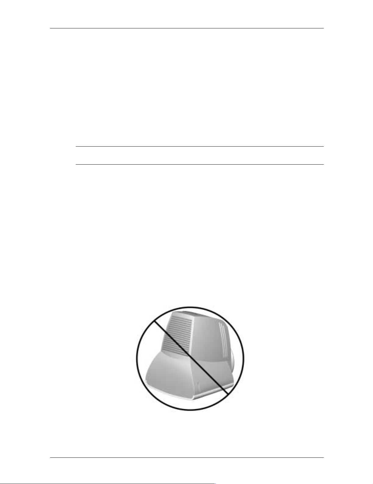
■ Do not place the monitor face down. Damage could result to the front panel controls or
the monitor screen.
2–2 Reference Guide
Page 8

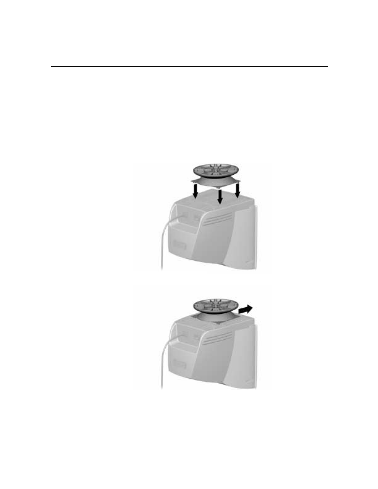
Removing the Monitor Base
In the event that you need to disassemble the base from the monitor, follow these
instructions:
1. If you must remove the base attachment, release the catch and slide the base toward the
back of your monitor.
2. Lift the base up and away from your monitor.
Safety and Maintenance Guidelines
Reference Guide 2–3
Page 9
MonitorBaseInstallation
On some monitors, the base must be attached prior to monitor installation. If you need to
attach the base, follow these steps:
1. Align the hooks on the base with the sock ets on the bottom of the monitor and attach the
base.
3
Installation
2. Push the base toward the front of the monitor until it stops.
Reference Guide 3–1
Page 10

Installation
Monitor Installation
Before installing your monitor, place it in a convenient, well-ventilated location near your
computer.
1. Turn off the power to your computer and other peripheral devices.
2. Connect the video cable (blue connector) 1 from the back of the monitor to the blue
15-pin connector on the back of the computer. Tighten the cable screws to secure the
cable to the connector.
Ä
CAUTION: To avoid damaging the video cable, ensure that the cable aligns with the
15-pin connector. Do not force the cable onto the connector.
3. Connect the power cord 2 to the back of the monitor, then connect the power cord to a
power outlet.
4. Power on your computer and monitor.
✎
If your monitor fails to function properly, refer to “Troubleshooting.”
5. If necessary, adjust the front panel monitor controls according to your personal
preference. See “Front Panel Controls” for detailed information.
Your monitor installation is now complete.
3–2 Reference Guide
Page 11

Speaker Installation
Selected monitors come with speakers which must be installed. If you need to install your
speakers, follow these steps:
1. Place the control speaker 1 and the other speaker 2 on either side of your monitor.
2. Attach the speaker power cable 3 to the black connector on the back of the control
speaker 1, then connect the AC adapter 4 into an electrical wall outlet.
3. Insert the white connector 5 from the other speak er 2 into the white port on the back of
the control speaker 1.
4. Attach the green connector 6 from the control speaker 1 to the green port on the back of
your computer.
Installation
You can attach your speakers to your monitor or place them on an even surface next to your
monitor. To attach the speakers, see the next section, “Attaching the Speakers to the
Monitor.”
Reference Guide 3–3
Page 12
Installation
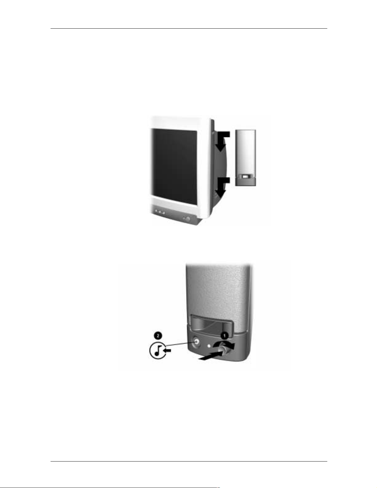
Attaching the Speakers to the Monitor
To attach the speakers to the sides of your monitor, follow these steps:
1. Rotate the thumbwheel, located on the side of the speak er, up to extend the speaker hook
mechanism
2. Align the hooks with the slots in the monitor.
3. Gently insert the hooks into the slots and slide down into place.
4. Turn the power/volume button 1 on the front of the speaker clockwise to power on the
speakers and adjust the speaker volume.
5. To use an MP3 or CD audio device with your speakers, connect the audio device cable to
the audio input jack 2 on the speaker . You must use a mini-stereo cable (3.5 mm/3.5mm
plug) to connect the audio device to the speaker.
3–4 Reference Guide
Page 13

Speaker Security Lock
If your monitor has speakers, the speakers can be locked to the sides of the monitor. To use
the Speaker Security Lock, follow these steps:
1. Grasp the front cloth-covered grill firmly at the sides and remove from the speaker, then
locate the security lock screw, which can be found in the top inner corner of the speaker.
2. Attach the speaker to the side of the monitor as described in the “Speaker Installation
section.”
3. Using a Phillips screwdriver, loosen the security lock screw, but do not remove it.
4. Slide the security lock out from the speaker until it engages the slot in the side of the
monitor.
Installation
5. Once the lock is in place in the side of the monitor, tighten the security lock screw to
secure the speaker to the monitor.
6. Reattach the grill to the speaker.
7. Repeat this process for the other speaker.
Reference Guide 3–5
Page 14

Information Files
The CD-ROM included with this monitor contains two data files that must be installed onto
your computer: an .INF file and an .ICM file.
The .INF file designates software and defines monitor resources used b y Microsoft W indo ws
to ensure monitor compatibility with the graphics adapter in your computer.
The .ICM file provides color matching consistency between your monitor screen and your
printer. Once installed, this file is activated by graphics programs that have this
color-matching feature.
To install these files on your computer:
1. Insert the Software and Reference Guide CD-ROM in your computer's optical drive.
2. When the CD-ROM menu launches, select Install INF and ICM Files.
3. To get the latest .INF and .ICM files, download them from the Compaq Web site. Access
http://www.compaq.com/support/files/monitors/index.html and select your monitor model to
download the appropriate files.
4
Operation
Front Panel Controls
Reference Guide 4–1
Page 15

Operation
Front Panel Controls
Item Icon Name Function
Select Launches on-screen displays, selects functions and
1
Left Adjustment Moves backward through menu options or decreases
2
Right Adjustment Moves forward through menu options or increases
3
Power/LED Controls power to themonitor. The LED on the power button
4
adjustments, and exits menus and On-Screen Display.
adjustment levels.
adjustment levels.
indicates the state of the monitor.
On-Screen Display
The On-Screen Display (OSD) adjusts the screen image based on your viewing preferences.
To access the OSD, do the following:
1. If the monitor is not already on, press the Power button to turn on the monitor.
2. Press the Select button to display the On-Screen Display menu. A screen similar to this
one appears. For a description of the icons that appear on the screen, see “On-Screen
Display Functions” later in this chapter.
✎
4–2 Reference Guide
different. See “On-Screen Display Functions” for a features list for your model.
Not all OSD features are available on all models. The OSD for your monitor may be
Page 16
3. To move to a function, press the Right-Adjustment or Left-Adjustment button on the
front panel of your monitor until the function is highlighted.
4. Press the Select button on the monitor choose the function.
5. The adjustment window displays. Press the Right-Adjustment or Left-Adjustment
buttons to increase (Right) or decrease (Left) the level of adjustment.
6. Press Select to save the new adjustment.
7. To exit the On-Screen Display, select the Exit icon and press the Select button once.
On-Screen Display Functions
Use the Right-Adjustment and Left-Adjustment buttons found on the front control panel of
your monitor to adjust these functions.
Operation
✎
The shaded area indicates that this function is available in the model indicated.
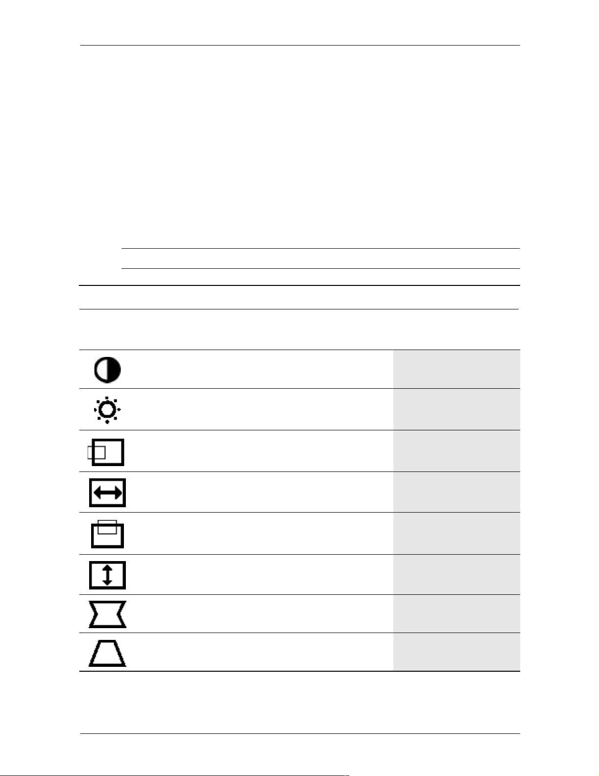
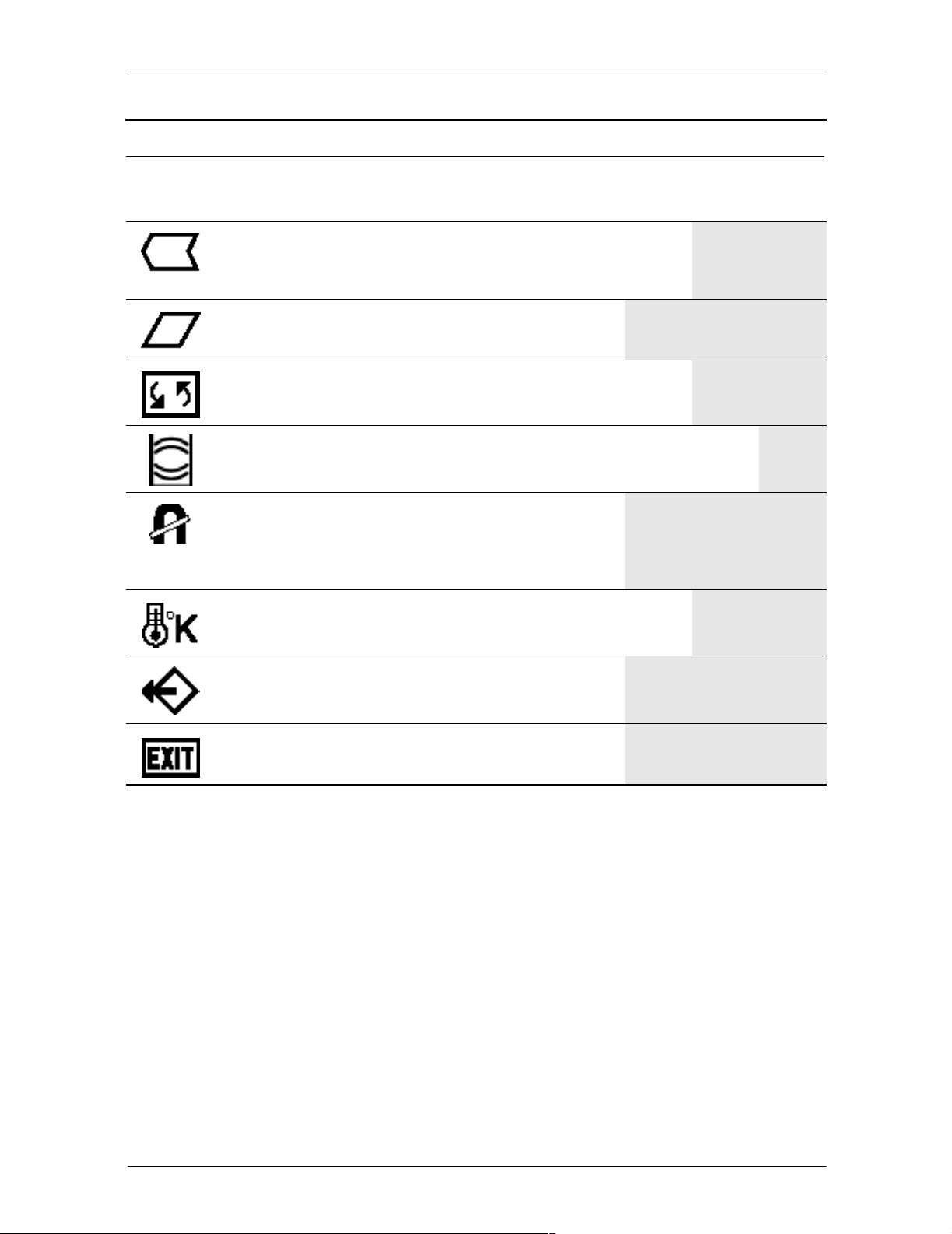
On-Screen Display Icons and Functions
Icon Function Description 5500
Contrast Right-Adjustment increases thecontrast and
Left-Adjustment decreases the contrast.
Brightness Right-Adjustment increases the brightness
and Left-Adjustment decreases the
brightness.
Horizontal
Position
Horizontal
Size
Vertical
Position
Right-Adjustment moves the image to the
right and Left-Adjustment moves the image
to the left.
Right-Adjustment increases the horizontal
size and Left-Adjustment decreases the
horizontal size.
Right-Adjustment moves the image up and
Left-Adjustment moves the image down.
7500
&
7550 9500
Vertical Size Right-Adjustmentincreases the vertical size
and Left-Adjustment decreases the vertical
size.
Pincushion Right-Adjustment makes the image sides
convex and Left-Adjustment makes the
image concave.
Trapezoid Right-Adjustment adjusts the image so the
top is larger and Left-Adjustment adjusts the
image so that the bottom is larger.
Reference Guide 4–3
Page 17
Operation
On-Screen Display Icons and Functions (Continued)
Icon Function Description 5500
Pin Balance Right-Adjustment moves the top and bottom
of the imageto the right and Left-Adjustment
moves the top and bottom of the image to the
left.
7500
&
7550 9500
Parallelogram
Tilt (Rotation) Right-Adjustment tilts the sides of the image
Moire Right-Adjustment increases the Moire
Degauss This control demagnetizes the screen to
Right-Adjustment tilts the sides of the image
to the right and Left-Adjustment tilts the sides
of the image to the left.
to the right and Left-Adjustment tilts the sides
of the image to the left.
correction and Left-Adjustment decreases
the Moire correction.
reduce color impurities.
Compaq suggests you not degauss
more than once within a 30-minute
period of time.
Color Temp Right-Adjustment selects the color
temperature to the right and Left-Adjustment
selects the color temperature to the left.
Reset This control resets the monitor to factory
default values.
Exit This control exits the OSD menu.
4–4 Reference Guide
Page 18

Monitor Messages
No Signal Message
Operation
If a No Signal message displays on your monitor, check to be sure your video cable is
properly connected and ensure that your computer is powered on.
Out of Frequency Range Message
If an Out of Frequency Range message displays on your monitor, your video resolution
and/or refresh rate are set higher than the levels your monitor supports.
To change the video resolution or refresh rate on your monitor, follow these steps:
1. Restart your computer.
2. Enter Safe Mode on your computer. Refer to your computer’s operating system Help for
instructions on entering Safe Mode.
Reference Guide 4–5
Page 19

Operation
3. Change your display settings to a supported setting (see “Technical Specifications”).
4. Restart your computer so that the new settings take effect.
Using the Energy Saver Mode
Your monitor is designed to meet strict Environmental Protection Agency (EPA) Energy Star
requirements for reduced power consumption. Using a combination of hardware and
software functions, this energy-saving feature allows your computer to control your
monitor’s power consumption and reduce your monitor’s power state when not in use.
Power Management Status for 5500/15” Series Monitors
(CV, MV, S)
LED
State
On Green < 80 watts Normal Operation
Sleep Amber < 5 watts Monitor screen is blank. High
Color
Power
Consumption Description
voltage is off. Heater voltage is
off. There is a brief warm-up
period before returning to full
power mode.
Power Management Status for 7500 and 7550/17” Series Monitors
(CV,MV,S,FS,V)
LED
State
On Green < 100 watts Normal Operation
Sleep Amber < 5 watts Monitor screen is blank. High
Color
Power
Consumption Description
voltage is off. Heater voltage is
off. There is a brief warm-up
period before returning to full
power mode.
Power Management Status for 9500/19” Series Monitors
(MV, S)
LED
State
On Green < 130 watts Normal Operation
Sleep Amber < 5 watts Monitor screen is blank. High
4–6 Reference Guide
Color
Power
Consumption Description
voltage is off. Heater voltage is
off. There is a brief warm-up
period before returning to full
power mode.
Page 20

Operation
✎
Your monitor’s energy saver feature works only when your monitor is connected to a
computer that also has energy saver features.
The Energy Saver utility, with its energy saving features, is available with all Microsoft
Windows operating systems. Some features are also available in DOS. Refer to your
computer’s user guide for instructions on setting energy saver features (also referred to as
power management features).
Reference Guide 4–7
Page 21

Solving Common Problems
The following table lists possible problems, the possible cause of each problem, and the
recommended solutions.
Problem Possible Cause Solution
Screen is blank. Power cord is disconnected. Connect the power cord.
Power switch is off. Turn on power.
A
Troubleshooting
Video cable is improperly
connected.
Screen blanking utility is
active.
Image appears
blurred, indistinct, or
too dark.
Color is abnormal. A magnetic object may be
Image is too large or
too small.
Brightness and contrast are
too low.
nearby.
Monitor may have been
moved or inadvertently
bumped.
Horizontal width may need
adjustment.
Connect video cable properly.
Depress any key on the
keyboard or move the mouse.
Press the SELECT button to
access the On-Screen
Display. Select the Brightness
and/or Contrast icons to
adjust as needed.
Move the object farther away.
Press the SELECT button to
access the On-Screen
Display. Select Degauss to
activate.
Compaq suggests you not
degauss more than once
within a 30-minute period of
time.
Press the SELECT button to
access the On-Screen
Display. Select H. Size to
adjust as needed.
Vertical height may need
adjustment.
Image is not
centered.
Reference Guide A–1
Horizontal position may need
adjustment.
Press the SELECT button to
access the On-Screen
Display. Select V. Size to
adjust as needed.
Press the SELECT button to
access the On-Screen
Display. Select H. Position to
adjust as needed.
Page 22

Problem Possible Cause Solution
Vertical position may need
adjustment.
“No Signal” is
displayed on screen.
“Out of Frequency” is
displayed on screen.
Monitor video cable is
disconnected.
Video resolution and/or
refresh rate are set higher
than what your monitor
supports.
No speaker power. Speaker power cord is
disconnected.
Power button on right-side
speaker may be off.
Press the SELECT button to
access the On-Screen
Display. Select V. Position to
adjust as needed.
Connect the 15-pin monitor
video cable to the computer.
Be sure that the computer
power is on.
Restart your computer and
enter Safe Mode. Change
your settings to a supported
setting (see “Technical
Specifications”). Restart your
computer so that the new
settings take effect.
Check all speaker power
connections and make sure
they are properly connected.
Turn the power button
clockwise on the front
of the right-side speaker.
Speaker LED should
illuminate.
No sound from
speakers.
Speaker audio plug may be
disconnected from the back
of the computer.
Make sure your audio input
jack (green connector) is
plugged into the back of your
computer.
Mute button may be
activated.
Select the Speaker icon on
your computer screen and
deselect Mute.
Volume may be too low. Increase volume by using
keyboard volume control or
clicking on the Speaker icon
on your computer screen and
increasing the volume level.
Volumemayalsobeadjusted
on the speaker.
A–2 Reference Guide
Page 23

Problem Possible Cause Solution
No sound from left
speaker.
Monitor is
overheating.
Speaker audio cable is
disconnected.
Left speaker balance may
need to be adjusted.
There is not enoughair space
to allow proper ventilation.
Using the World Wide Web
Support services are available on the Internet through the Compaq Support F o rum. You can
either browse the postings as a guest, or register as a user and submit your own questions.
Compaq responds to questions within one business day.
To access the Compaq Support Forum, go to the Compaq Web site at:
Make sure the speaker
connection from the left-side
speaker is connected to the
rear of the right-side speaker.
Select the Speaker icon
located on your Windows
desktop and adjust the
left-right balance accordingly.
Leave at least 3 inches (76
mm) of ventilation space
around the monitor, and do
not place objects on top ofthe
monitor.
http://www.compaq.com
Preparing to Call Technical Support
If you cannot solve a problem using the troubleshooting tips in this section, you may need to
call technical support. Have the following information available when you call:
■ The monitor
■ Monitor model number
■ Serial number for the monitor
■ Purchase date on invoice
■ Conditions under which the problem occurred
■ Error messages received
■ Hardware configuration
■ Hardware and software you are using
Reference Guide A–3
Page 24

Technical Specifications
Compaq 5500/15” Series Monitor
5500 CV, MV, S
Screen Size 15” (38 cm) visual diagonal
Dot Pitch 0.28 mm (Diagonal)
Display Area Default 199 x 265 (mm) typical
Display Colors Infinite
B
Viewable screen size 13.8” (35 cm)
Display Resolutions
640 x 480
640 x 480
640 x 480
720 x 400
800 x 600
800 x 600
1024 x 768
Synchronization (Horizontal) 30 to 54 KHz
Synchronization (Vertical) 50 to 120 Hz
Max Pixel Clock 70 MHz Max.
Input Signal Video RGB Analog Sync. TTL
Video Cable 15-pin D-sub connector
Power Input Voltage Frequency 100 to 240V AC
Inrush Current 30 amps @ 120V
Power Consumption 80 W (Max.)
Dimension (W x H x D) Unpacked
w/attached base
Refresh Rates
60 Hz
75 Hz
85 Hz
70 Hz
75 Hz
85 Hz (preferred resolution)
60 Hz (maximum resolution)
Separate
50 +
3to60+3Hz
60 amps @ 220V
14.4 x 15.7 x 16.5 inches
(maximum)
365 x 400 x 418 mm (maximum)
Weight 29 lb Max.
13 kg Max.
Operating Temperature 50
Reference Guide B–1
o
Fto95oF
o
10
Cto35oC
Page 25

Technical Specifications
5500 CV, MV, S (Continued)
o
-30
o
Fto140oF
Cto60oC
Storage Temperature -22
Humidity 20% to 80% (non-condensing)
Altitude Up to 10,000 ft./3048 meters
TCO’99 Some models meet TCO’99
MPRII Some models meet MPRII
Plug and Play Yes
B–2 Reference Guide
Page 26

Compaq 7500/17” Series Monitor
7500 CV, MV, S
Screen Size 17” (43 cm) visual diagonal
Dot Pitch 0.28 mm (Diagonal)
Display Area Default 234 x 312 (mm) typical
Display Colors Infinite
Technical Specifications
Viewable screen size 16” (40.6 cm)
Display Resolutions
640 x 480
640 x 480
640 x 480
720 x 400
800 x 600
800 x 600
1024 x 768
1024 x 768
1280 x 1024
Synchronization (Horizontal) 30 to 70 KHz
Synchronization (Vertical) 50 to 140 Hz
Max Pixel Clock 110MHz Max.
Input Signal Video RGB Analog Sync. TTL
Video Cable 15-pin D-sub connector
Power Input Voltage Frequency 100 to 240V AC
Inrush Current 30 amps @ 120V
Power Consumption 100 W (Max.)
Refresh Rates
60 Hz
75 Hz
85 Hz
70 Hz
75 Hz
85 Hz
75 Hz
85 Hz (preferred user resolution)
60 Hz (maximum resolution)
Separate
50 +
3to60+3Hz
60 amps @ 220V
Dimension (W x H x D) Unpacked
w/attached base
Weight 38 lb Max.
Operating Temperature 50
Storage Temperature -22
Humidity 20% to 80% (non-condensing)
Altitude Up to 10,000 ft./3048 meters
TCO’99 Some models meet TCO’99
MPRII Some models meet MPRII
Plug and Play Yes
Reference Guide B–3
16.6 x 17 x 17.5 inches (maximum)
410 x 432 x 445 mm (maximum)
17 kg Max.
o
Fto95oF
o
10
Cto35oC
o
Fto140oF
o
-30
Cto60oC
Page 27

Technical Specifications
Compaq 7550/17” Flat CRT Monitor
7550 FS, V
Screen Size 17” (43 cm) visual diagonal
Dot Pitch 0.25 to 0.28 mm (variable)
Display Area Default 234 x 312 (mm) typical
Display Colors Infinite
Display Resolutions
640 x 480
640 x 480
640 x 480
720 x 400
800 x 600
800 x 600
1024 x 768
1024 x 768
1280 x 1024
1600 x 1200
Viewable screen size 16” (40.6 cm)
Anti-Glare Coating
Refresh Rates
60 Hz
75 Hz
85 Hz
70 Hz
75 Hz
85 Hz
75 Hz
85 Hz (preferred user resolution)
75 Hz
65 Hz (maximum resolution)
Synchronization (Horizontal) 30 to 86 KHz
Synchronization (Vertical) 50 to 140 Hz
Max Pixel Clock 180 MHz Max.
Input Signal Video RGB Analog Sync. TTL
Separate
Video Cable 15-pin D-sub connector
Power Input Voltage Frequency 100 to 240V AC
50 +
3to60+3Hz
Inrush Current 30 amps @ 120V
60 amps @ 220V
Power Consumption 100 W (Max.)
Dimension (W x H x D) Unpacked
w/attached base
Weight 42 lb Max.
Operating Temperature 50
Storage Temperature -22
16.1 x 17 x 17.4 inches (maximum)
410 x 432 x 442 mm (maximum)
19 kg Max.
o
Fto95oF
o
10
Cto35oC
o
Fto140oF
o
-30
Cto60oC
Humidity 20% to 80% (non-condensing)
Altitude Up to 10,000 ft./3048 meters
B–4 Reference Guide
Page 28

7550 FS, V (Continued)
TCO’99 Some models meet TCO’99
MPRII Some models meet MPRII
Plug and Play Yes
Technical Specifications
Reference Guide B–5
Page 29

Technical Specifications
Compaq 9500/19” Series Monitor
9500 MV, S
Screen Size 19” (48 cm) visual diagonal
Dot Pitch 0.26 mm (Diagonal)
Display Area Default 264 x 352 (mm) typical
Display Colors Infinite
Viewable screen size 18” (46 cm)
Anti-Glare Coating
0.22 mm (Horizontal)
Display Resolutions
640 x 480
640 x 480
720 x 400
800 x 600
800 x 600
1024 x 768
1024 x 768
1280 x 1024
1280 x 1024
1600 x 1200
Synchronization (Horizontal) 30 to 96 KHz
Synchronization (Vertical) 50 to 160 Hz
Max Pixel Clock 210 MHz Max.
Input Signal Video RGB Analog Sync. TTL
Video Cable 15-pin D-sub connector
Power Input Voltage Frequency European Models: 200 to 240V AC
Inrush Current 30 amps @ 120V
Refresh Rates
60 Hz
85 Hz
70 Hz
75 Hz
85 Hz
75 Hz
85 Hz
75 Hz
85 Hz (preferred user resolution)
75 Hz (maximum resolution)
Separate
Other Models: 100 to 240V AC
50 +
3to60+3Hz
60 amps @ 220V
Power Consumption 130 W (Max.)
Dimension (W x H x D) Unpacked
w/attached base
Weight 44 lb Max.
Operating Temperature 50
Storage Temperature -22
B–6 Reference Guide
17.9 x 18.5 x 18.7 inches
(maximum)
455 x 470 x 475 mm (maximum)
20 kg Max.
o
Fto95oF
o
10
Cto35oC
o
Fto140oF
o
-30
Cto60oC
Page 30

9500 MV, S (Continued)
Humidity 20% to 80% (non-condensing)
Altitude Up to 10,000 ft./3048 meters
TCO’99 Some models meet TCO’99
MPRII Some models meet MPRII
Plug and Play Yes
Technical Specifications
Reference Guide B–7
Page 31

Agency Regulatory Notices
Federal Communications Commission Notice
This equipment has been tested and found to comply with the limits for a Class B digital
device, pursuant to Part 15 of the FCC Rules. These limits are designed to provide
reasonable protection against harmful interference in a residential installation. This
equipment generates, uses, and can radiate radio frequency energy and, if not installed and
used in accordance with the instructions, may cause harmful interference to radio
communications. However, there is no guarantee that interference will not occur in a
particular installation. If this equipment does cause harmful interference to radio or
television reception, which can be determined by turning the equipment off and on, the user
is encouraged to try to correct the interference by one or more of the following measures:
■ Reorient or relocate the receiving antenna.
■ Increase the separation between the equipment and the receiver.
■ Connect the equipment into an outlet on a circuit different from that to which the
receiver is connected.
C
■ Consult the dealer or an experienced radio or television technician for help.
Modifications
The FCC requires the user to be notified that any changes or modifications made to this
device that are not expressly approved by Compaq Computer Corporation may void the
user's authority to operate the equipment.
Cables
Connections to this device must be made with shielded cables with metallic RFI/EMI
connector hoods to maintain compliance with FCC Rules and Regulations.
Declaration of Conformity for Products
Marked with FCC Logo, United States Only
This device complies with Part 15 of the FCC Rules. Operation is subject to the following
two conditions: (1) this device may not cause harmful interference, and (2) this device must
accept any interference received, including interference that may cause undesired operation.
For questions regarding your product, contact:
Compaq Computer Corporation
P. O. Box 692000, Mail Stop 530113
Houston, Texas 77269-2000
Or, call - 1-800- 652-6672 (1-800-OK COMPAQ)
For questions regarding this FCC declaration, contact:
Reference Guide C–1
Page 32

Agency Regulatory Notices
Compaq Computer Corporation
P. O. Box 692000, Mail Stop 510101
Houston, Texas 77269-2000
Or, call - (281) 514-3333
To identify this product, refer to the Part, Series, or Model number found on the product.
Canadian Notice
This Class B digital apparatus meets all requirements of the Canadian Interference-Causing
Equipment Regulations.
Avis Canadien
Cet appareil numérique de la classe B respecte toutes les exigences du Règlement sur le
matériel brouilleur du Canada.
European Union Notice
Products bearing the CE marking comply with the EMC Directive (89/336/EEC) and the
Low Voltage Directive (73/23/EEC) issued b y the Commission of the European Community,
and if this product has telecommunication functionality, the R&TTE Directive (1999/5/EC).
Compliance with these directives implies conformity to the following European Norms (in
parentheses are the equivalent international standards and regulations):
■ EN 55022 (CISPR 22)—Electromagnetic Interference
■ EN55024 (IEC61000 - 4-2,3,4,5,6,8,11) —Electromagnetic Immunity
■ EN61000-3-2 (IEC61000-3-2)—Power Line Harmonics
■ EN61000-3-3 (IEC61000-3-3)—Power Line Flicker
■ EN 60950 (IEC60950)—Product Safety
EPAEnergyStarCompliance
Monitors that are marked with the Energy Star Logo meet the requirements of the EPA
Energy Star program. As an Energy Star Partner, Compaq Computer Corporation has
determined that this product meets the Energy Star guidelines for energy efficiency. Specific
details on using the Energy Saving features can be found in the energy saver or power
management section of the computer manual.
Power Cord Set Requirements
The power cord used with your monitor must be rated for the product and for the voltage and
current marked on the product's electrical ratings label. The voltage and current rating of the
cord should be greater than the voltage and current rating marked on the product. In addition,
the cross section of the wire must be a minimum of 0.75 mm
the cord must be between 6 feet (1.8 m) and 12 feet (3.6 m). If you have questions about the
type of power cord to use, contact your Compaq authorized service provider.
²
or 18AWG, and the length of
C–2 Reference Guide
Page 33

Agency Regulatory Notices
A power cord should be routed so that it is not likely to be walked on or pinched by items
placed upon it or against it. Particular attention should be paid to the plug, electrical outlet,
and the point where the cord exits from the product. The monitor power supply is provided
with Automatic Line Switching (ALS). This feature allows the monitor to operate on input
voltages between 100-120V or 220-240V.
The power cord set (flexible cord or wall plug) received with the monitor meets the
requirements for use in the country where you purchased the equipment. For more
information on power cord set requirements, contact your Compaq authorized dealer , reseller
or service provider.
Reference Guide C–3
Page 34

D
TCO‘99 Requirements
You have just purchased a TCO'99 approved and labelled product. Your choice has provided
you with a product developed for professional use. Your purchase has also contributed to
reducing the burden on the environment and also to the further development of
environmentally adapted electronics products.
Why do we have environmentally labelled computers?
In many countries, environmental labelling has become an established method for
encouraging the adaptation of goods and services to the environment. The main problem, as
far as computers and other electronics equipment are concerned, is that environmentally
harmful substances are used both in the products and during their manufacture. Since it is not
so far possible to satisfactorily recycle the majority of electronics equipment, most of these
potentially damaging substances sooner or later enter nature.
There are also other characteristics of a computer, such as energy consumption levels, that
are important from the viewpoints of both the work (internal) and natural (external)
environments. Since all methods of electricity generation have a negative effect on the
environment (for example, acidic and climate-influencing emissions, radioactive waste), it is
vital to save energy. Electronics equipment in offices is often left running continuously and
thereby consumes a lot of energy.
What does labelling involve?
This product meets the requirements for the TCO'99 scheme which provides for international
and environmental labelling of personal computers. The labelling scheme was de veloped as a
joint effort by the TCO (The Swedish Confederation of Professional Employees), Svenska
Naturskyddsforeningen (The Swedish Society for Nature Conservation) and Statens
Energimyndighet (The Swedish National Energy Administration).
Approval requirements cover a wide range of issues: environment, ergonomics, usability,
emission of electric and magnetic fields, energy consumption and electrical and fire safety.
The environmental demands impose restrictions on the presence and use of heavy metals,
brominated and chlorinated flame retardants, CFCs (freons) and chlorinated solvents, among
other things. The product must be prepared for recycling and the manufacturer is obligated to
have an environmental policy which must be adhered to in each country where the company
implements its operational policy.
Reference Guide D–1
Page 35

TCO‘99 Requirements
The energy requirements include a demand that the computer and/or display, after a certain
period of inactivity, shall reduce its power consumption to a lower level in one or more
stages. The length of time to reactivate the computer shall be reasonable for the user.
Labelled products must meet strict environmental demands, for example, in respect of the
reduction of electric and magnetic fields, physical and visual ergonomics and good usability.
Below you will find a brief summary of the environmental requirements met by this product.
The complete environmental criteria document may be ordered from:
TCO Development
SE-114 94 Stockholm, Sweden
Fax: +46 8 782 92 07
Email (Internet): development@tco.se
Current information regarding TCO'99 approved and labelled products may also be obtained
via the Internet, using the address:
http://www.tco-info.com
Environmental Requirements
Flame Retardants
Flame retardants are present in printed circuit boards, cables, wires, casings and housings.
Their purpose is to prevent, or at least to delay the spread of fire. Up to 30% of the plastic in
a computer casing can consist of flame retardant substances. Most flame retardants contain
bromine or chloride, and those flame retardants are chemically related to another group of
environmental toxins, PCBs. Both the flame retardants containing bromine or chloride and
the PCBs are suspected of giving rise to sev ere health effects, including reproducti v e damage
in fish-eating birds and mammals, due to the bioaccumulative processes. Flame retardants
have been found in human blood and researchers fear that disturbances in foetus
development may occur.
The relevant TCO'99 demand requires that plastic components weighing more than 25 grams
must not contain flame retardants with organically bound bromine or chlorine. Flame
retardants are allowed in the printed circuit boards since no substitutes are available.
Bioaccumulative is defined as substances which accumulate within living
✎
organisms.
Cadmium
Cadmium is present in rechargeable batteries and in the color-generating layers of certain
computer displays. Cadmium damages the nervous system and is toxic in high doses. The
relevant TCO'99 requirement states that batteries, the color-generating layers of display
screens and the electrical or electronics components must not contain any cadmium.
Cadmium is a heavy metal that is Bioaccumulative.
✎
D–2 Reference Guide
Page 36

Mercury
Mercury is sometimes found in batteries, relays and switches. It damages the nervous system
and is toxic in high doses. The relevant TCO'99 requirement states that batteries may not
contain any mercury. It also demands that mercury is not present in any of the electrical or
electronics components associated with the labelled unit. There is however one exception.
Mercury is, for the time being, permitted in the back light system of flat panel monitors as
there today is no commercially available alternative. TCO aims on removing this exception
when a mercury free alternative is available.
Mercury is a heavy metal that is Bioaccumulative.
✎
CFCs (Freons)
The relevant TCO'99 requirement states that neither CFCs nor HCFCs may be used during
the manufacture and assembly of the product. CFCs (freons) are sometimes used for washing
printed circuit boards. CFCs break down ozone and thereby damage the ozone layer in the
stratosphere, causing increased reception on earth of ultraviolet light with e.g. increased risks
of skin cancer (malignant melanoma) as a consequence.
TCO‘99 Requirements
Lead
✎
Lead can be found in picture tubes, display screens, solders and capacitors. Lead damages
the nervous system and in higher doses, causes lead poisoning. The relevant TCO´99
requirement permits the inclusion of lead since no replacement has yet been developed.
Lead is a heavy metal that is Bioaccumulative.
Reference Guide D–3
 Loading...