

Page 1

Infortrend
External RAID Controller & Subsystem
Generic Operation Manual
Revision 1.61
Firmware Version: 3.31
Page 2

Asia Pacific
(International hea dquarter)
Infortrend Technology, Inc.
8F, No. 102 Chung-Shan Rd., Sec. 3
Chung-Ho City, Taipei Hsien, Taiwan
Tel: (886)-2-2226-0126
Fax: (886)-2-2226-0020
sales@infortrend.com.tw
support@infortrend.com.tw
www.infortrend.com.tw
Americas
Infortrend Corporation
3150 Coronado Drive, Unit C
Santa Clara, CA 95054, USA
Tel: (408) 988-5088
Fax: (408) 988-6288
sales@infortrend.com
support@infortrend.com
www.infortrend.com
China
Infortrend Technology, Limited
Room 1236 Tower C Corporate Square
No. 35 Financial Street Xicheng District
Beijing China 100032
Tel: (86)-10-88091540
Fax: (86)-10-88092126
sales@infortrend.com.cn
support@infortrend.com.cn
www.infortrend.com.cn
Copyright © 2003
This Edition First Published 2003
All rights reserved. No part of this publication may be
reproduced, transmitted, transcribed, stored in a retrieval
system, or translated into any language or computer language,
in any form or by any means, electronic, mechanical, magnetic,
optical, chemical, manual or otherwise, without the prior
written consent of Infortrend Tec hnology, Inc.
Disclaimer
Infortrend Technology makes no representations or warr anties
with respect to the contents hereof and specifically disclaims
any implied warranties of merchantability or fitness for any
particular purpose. Furthermore, Infortrend Technology
reserves the right to revise this publication and to make
changes from time to time in the content hereof without obligation to notify any person of such revisions or changes.
Product specifications are also subject to change without
notice.
Europe
Infortrend Europe Limited
Ground Floor, Chancery House
St. Nicholas Way, Sutton,
Surrey, SM1 1JB, United Kingdom
Tel:+44-(0)20 8770 1838
Fax:+44-(0)20 8770 7409
sales@infortrend-europe.com
support@infortrend-europe.com
www.infortrend-europe.com
Trademarks
Infortrend and the Infortrend logo are registered trademarks
and SentinelRAID, EonRAI D, EonStor, RAIDWatch, and other
names prefixed with “IFT” are trademarks of Infortrend
Technology, Inc.
PowerPC is a registered trademark of International Business
Machines Corporation and Motorola Inc.
ii
Page 3

DEC and Alpha are registered trademarks of Compaq
Computer Corp. (formerly of Digital Equipment Corporation).
Microsoft, Windows, Windows NT and MS- DOS a re r egistered
trademarks of Microsoft Corporation in the U.S. and other
countries.
Novell and NetWare are registered trademarks of Novell, Inc.
in the U.S. and other countries.
SCO, OpenServer, and UnixWare are trademarks or registered
trademarks of The Santa Cruz Operation, Inc. in the U.S. and
other countries.
Solaris is a trademark of SUN Microsystems, Inc.
UNIX is a registered trademark of The Open Group in the U.S.
and other countries. All other names, brands, products or
services are trademarks or registered trademarks of their
respective companies.
RMA Policy
Please visit our websites
(www.infortrend.com/www.infortrend.com.tw/ww.infortrend.com.cn/
www.infortrend-europe.com) where our RMA policy is given a
detailed explanation.
Supported Models
This manual supports the following Infortrend
controllers/subsystems:
• SentinelRAID: SCSI-based external RAID controllers
(including the 5.25” full-height and 1U canister
configuration)
• EonRAID: Fibre-based external RAID controllers
(including the 5.25” full-height and 1U canister
configuration)
• EonStor: subsystems that come with SCSI or Fibre host
channels.
• IFT-6230 and 6330 series ATA RAID subsystems.
Printed in Taiwan
iii
Page 4

Table of Contents
Chapter 1 RAID Functions: An Introduction
1.1 Logical Drive...................................................................................................1
1.2 Logical Volume...............................................................................................1
What is a logical volume?..................................................................................1
1.3 RAID Levels.....................................................................................................2
What are the RAID levels? ................................................................................ 2
NRAID................................................................................................................3
JBOD.................................................................................................................3
RAID 0...............................................................................................................4
RAID 1...............................................................................................................4
RAID (0+1).........................................................................................................4
RAID 3...............................................................................................................5
RAID 5...............................................................................................................5
1.4 Spare Drives ...................................................................................................6
Global and Local Spare Drives..........................................................................6
1.5 Identifying Drives...........................................................................................8
Flash Selected SCSI Drive................................................................................8
Flash All SCSI Drives ........................................................................................ 8
Flash All but Selected Drives.............................................................................8
1.6 Rebuild ............................................................................................................9
Automatic Rebuild and Manual Rebuild.............................................................9
1. Automatic Rebuild ........................................................................................9
2. Manual Rebuild...........................................................................................10
3. Concurrent Rebuild in RAID (0+1)..............................................................11
1.7 Logical Volume (Multi-Level RAID)............................................................. 12
What is a logical volume?................................................................................12
Spare drives assigned to a logical volume? ....................................................14
Limitations:.......................................................................................................15
Partitioning - partitioning the logical drive or partitioning the logical volume? .15
Different write policies within a logical volume?............................................... 16
RAID expansion with logical volume?..............................................................16
Different controller settings using logical volume? .......................................... 16
A logical volume with logical drives of different levels?...................................17
Multi-level RAID systems.................................................................................17
Chapter 2 RAID Planning
2.1 Considerations...............................................................................................1
2.2 Configuring the Array:................................................................................... 5
2.2.1 Starting a RAID System...........................................................................5
2.3 Operation Theory ...........................................................................................7
2.3.1 I/O Channel, SCSI ID, and LUN .............................................................. 7
2.3.2 Grouping Drives into an Array .................................................................7
2.3.3 Making Arrays Available to Hosts............................................................ 9
2.4 Tunable Parameters.....................................................................................10
Chapter 3 Accessing the Array through Serial Port and Ethernet
3.1 RS-232C Serial Port....................................................................................... 1
iv
Page 5

3.1.1 Configuring RS-232C Connection via Front Panel ..................................2
3.1.2 Starting RS-232C Terminal Emulation.....................................................3
3.2 Out-of-Band via Ethernet..............................................................................4
What Is the “Disk Reserved Space?”.................................................................4
Other Concerns..................................................................................................5
Web-Based Management..................................................................................5
Requirements.....................................................................................................5
3.2.1 Connecting Ethernet Port:........................................................................5
3.2.2 Configuring the Controller........................................................................6
3.2.3 NPC Onboard ..........................................................................................9
The SNMP_TRAP section ...............................................................................10
The EMAIL section...........................................................................................10
The BROADCAST section...............................................................................10
Chapter 4 LCD Screen Messages
4.1 The Initial Screen............................................................................................1
4.2 Quick Installation Screen...............................................................................1
4.3 Logical Drive Status.......................................................................................2
4.4 Logical Volume Status...................................................................................3
4.5 SCSI Drive Status ...........................................................................................4
4.6 SCSI Channel Status......................................................................................5
4.7 Controller Voltage and Temperature ............................................................6
4.8 Cache Dirty Percentage .................................................................................7
4.9 View and Edit Event Logs..............................................................................7
Chapter 5 LCD Keypad Operation
5.1 Power on RAID Enclosure ............................................................................1
5.2 Caching Parameters......................................................................................1
Optimization Modes ...........................................................................................1
Optimization Mode and Stripe Size....................................................................2
Optimization for Random or Sequential I/O .......................................................3
Write-Back/Write-Through Cache Enable/Disable ............................................3
5.3 View Connected Drives:................................................................................5
5.4 Creating a Logical Drive................................................................................6
Choosing a RAID Level:.....................................................................................6
Choosing Member Drives: .................................................................................6
Logical Drive Preferences:.................................................................................6
Maximum Drive Capacity:..................................................................................7
Spare Drive Assignments: .................................................................................7
Disk Reserved Space: .......................................................................................7
Write Policy:.......................................................................................................7
Initialization Mode: .............................................................................................7
Stripe Size:.........................................................................................................8
Beginning Initialization........................................................................................8
5.5 Creating a Logical Volume..........................................................................10
Initialization Mode ............................................................................................10
Write Policy......................................................................................................10
5.6 Partitioning a Logical Drive/Logical Volume .............................................12
5.7 Mapping a Logical Volume/Logical Drive to Host LUN.............................13
5.8 Assigning Spare Drive and Rebuild Settings.............................................14
Adding a Local Spare Drive .............................................................................14
Adding a Global Spare Drive............................................................................15
Rebuild Settings...............................................................................................15
v
Page 6

5.9 Viewing and Editing Logical Drives and Drive Members.........................16
Deleting a Logical Drive...................................................................................16
Deleting a Partition of a Logical Drive.............................................................. 17
Assigning a Name to a Logical Drive...............................................................18
Rebuilding a Logical Drive...............................................................................18
Regenerating Logical Drive Parity...................................................................19
Media Scan......................................................................................................20
Write Policy......................................................................................................21
5.10 Viewing and Editing Host LUNs................................................................. 22
Viewing and Deleting LUN Mappings..............................................................22
Pass-through SCSI Commands ......................................................................22
5.11 Viewing and Editing SCSI Drives...............................................................23
Scanning New SCSI Drive...............................................................................23
Identifying a Drive............................................................................................ 24
Deleting Spare Drive (Global / Local Spare Drive) .......................................... 25
5.12 Viewing and Editing SCSI Channels .........................................................25
Redefining Channel Mode...............................................................................25
Setting a SCSI Channel’s ID - Host Channel...................................................26
Viewing IDs......................................................................................................26
Adding a Channel ID........................................................................................26
Deleting a Channel ID......................................................................................27
Setting a SCSI Channel’s Primary ID - Drive Channel ...................................27
Setting a SCSI Channel’s Secondary ID - Drive Channel ...............................28
Setting Channel Bus Terminator .....................................................................28
Setting Transfer Speed....................................................................................29
Setting Transfer Width..................................................................................... 30
Viewing and Editing SCSI Target - Drive Channel ..........................................30
Slot Number.....................................................................................................31
Maximum Synchronous Transfer Clock ..........................................................31
Maximum Transfer Width................................................................................ 31
Parity Check .................................................................................................... 32
Disconnecting Support.....................................................................................32
Maximum Tag Count ....................................................................................... 32
Restore to Default Setting................................................................................33
5.13 System Functions ....................................................................................... 34
Mute Beeper....................................................................................................34
Change Password ........................................................................................... 34
Changing Password.........................................................................................34
Disabling Password.........................................................................................35
Reset Controller...............................................................................................35
Shutdown Controller........................................................................................35
Controller Maintenance....................................................................................36
Saving NVRAM to Disks.................................................................................. 36
Restore NVRAM from Disks............................................................................36
5.14 Controller Parameters................................................................................. 37
Controller Name ..............................................................................................37
LCD Title Display Controller Name..................................................................37
Password Validation Timeout..........................................................................37
Controller Unique Identifier..............................................................................37
Controller Date and Time ................................................................................38
Time Zone .......................................................................................................38
Date and Time.................................................................................................39
5.15 SCSI Drive Utilities......................................................................................40
SCSI Drive Low-level Format .......................................................................... 40
SCSI Drive Read/Write Test............................................................................ 41
vi
Page 7

Chapter 6 Terminal Screen Messages
6.1 The Initial Screen............................................................................................1
6.2 Main Menu.......................................................................................................2
6.3 Quick Installation............................................................................................2
6.4 Logical Drive Status.......................................................................................4
6.5 Logical Volume Status...................................................................................5
6.6 SCSI Drive Status ...........................................................................................6
6.7 SCSI Channel’s Status...................................................................................7
6.8 Controller Voltage and Temperature ............................................................9
6.9 Viewing Event Logs on the Screen.............................................................10
Chapter 7 Terminal Operation
7.1 Power on RAID Enclosure .............................................................................1
7.2 Caching Parameters.......................................................................................1
Optimization Modes ...........................................................................................1
Optimization Mode and Stripe Size....................................................................3
Optimization for Random or Sequential I/O .......................................................3
Write-Back/Write-Through Cache Enable/Disable ............................................3
7.3 Viewing the Connected Drives......................................................................4
7.4 Creating a Logical Drive.................................................................................5
Choosing a RAID Level:.....................................................................................6
Choosing Member Drives: .................................................................................6
Logical Drive Preferences:.................................................................................6
Maximum Drive Capacity:..................................................................................6
Assign Spare Drives: .........................................................................................7
Disk Reserved Space ........................................................................................7
Logical Drive Assignments:................................................................................7
Write Policy........................................................................................................7
Initialization Mode ..............................................................................................8
Stripe Size..........................................................................................................8
7.5 Creating a Logical Volume...........................................................................10
7.6 Partitioning a Logical Drive/Logical Volume .............................................11
7.7 Mapping a Logical Volume to Host LUN ....................................................13
7.8 Assigning Spare Drive, Rebuild Settings...................................................15
Adding Local Spare Drive ................................................................................15
Adding a Global Spare Drive............................................................................16
7.9 Viewing and Editing Logical Drive and Drive Members ...........................16
Deleting a Logical Drive...................................................................................17
Deleting a Partition of a Logical Drive..............................................................17
Assigning a Name to a Logical Drive...............................................................17
Rebuilding a Logical Drive ...............................................................................18
Regenerating Logical Drive Parity....................................................................19
Media Scan......................................................................................................19
Write Policy......................................................................................................20
7.10 Viewing and Editing Host LUNs..................................................................21
Viewing or Deleting LUN Mappings .................................................................21
Edit Host-ID/WWN Name List..........................................................................21
Pass-through SCSI Commands.......................................................................21
7.11 Viewing and Editing SCSI Drives................................................................22
Scanning New Drive.........................................................................................23
Slot Number.....................................................................................................23
Drive Entry .......................................................................................................23
Identifying Drive ...............................................................................................23
vii
Page 8

Deleting Spare Drive (Global / Local Spare Drive) .......................................... 24
7.12 Viewing and Editing SCSI Channels ..........................................................25
Redefining Channel Mode...............................................................................25
Viewing and Editing SCSI IDs - Host Channel ................................................26
Viewing and Editing SCSI IDs .........................................................................26
Adding a SCSI ID (Primary/Secondary Controller ID) .....................................26
Deleting an ID.................................................................................................. 27
Setting a Primary Controller’s SCSI ID - Drive Channel..................................27
Setting a Secondary Controller’s SCSI ID - Drive Channel .............................28
Setting Channel Terminator.............................................................................28
Setting a Transfer Speed.................................................................................28
Drive Channel.................................................................................................. 28
Setting the Transfer Width............................................................................... 29
Viewing and Editing SCSI Target / Drive Channel........................................... 30
Slot Number.....................................................................................................30
Maximum Synchronous Transfer Clock ..........................................................31
Maximum Transfer Width................................................................................ 31
Parity Check .................................................................................................... 31
Disconnecting Support.....................................................................................32
Maximum Tag Count ....................................................................................... 32
Data Rate.........................................................................................................32
7.13 System Functions ........................................................................................ 34
Mute Beeper....................................................................................................34
Change Password ........................................................................................... 34
Changing the Password...................................................................................35
Setting a New Password..................................................................................35
Disabling the Password...................................................................................36
Reset Controller...............................................................................................36
Shutdown Controller........................................................................................36
7.14 Controller Parameters.................................................................................. 37
Controller Name ..............................................................................................37
LCD Title Display Controller Name..................................................................37
Saving NVRAM to Disks.................................................................................. 38
Restore NVRAM from Disks............................................................................38
Password Validation Timeout..........................................................................39
Controller Unique Identifier..............................................................................39
Set Controller Date and Time..........................................................................41
Time Zone .......................................................................................................41
Date and Time.................................................................................................41
7.15 Drive Information..........................................................................................42
View Drive Information.....................................................................................42
SCSI Drive Utilities ..........................................................................................42
SCSI Drive Low-level Format .......................................................................... 43
SCSI Drive Read/Write Test............................................................................ 44
Chapter 8 Fibre Operation
8.1 Overview .........................................................................................................1
8.2 Major Concerns ..............................................................................................2
8.3 Supported Features ....................................................................................... 4
Fibre Chip..........................................................................................................4
Multiple Target IDs:............................................................................................4
Drive IDs:........................................................................................................... 5
In-band Fibre and S.E.S. Support:.....................................................................5
8.4 Configuration: Host and Drive Parameters .................................................6
Channel Mode: .................................................................................................. 6
viii
Page 9

Primary and Secondary Controller IDs:..............................................................6
Redundant Controller Cache Coherency Channel (RCC Channel):..................7
View Channel WWN..........................................................................................7
View Device Port Name List (WWPN)...............................................................8
View and Edit Fibre Drive...................................................................................8
User-Assigned ID (Scan SCSI Drive) ................................................................8
View Drive Information.......................................................................................9
View and Edit Host-Side Parameters.................................................................9
1. Fibre Channel Connection Type:................................................................10
View and Edit Drive-Side Parameters..............................................................10
2. Drive-Side Dual Loop:.................................................................................10
Controller Unique Identifier ..............................................................................11
Controller Communications over Fibre Loops .................................................12
8.5 Multi-Host Access Control: LUN Filtering..................................................14
Creating LUN Masks........................................................................................15
WWN Name List..............................................................................................16
Logical Unit to Host LUN Mapping...................................................................16
LUN Mask (ID Range) Configuration: ..............................................................18
Filter Type: Include or Exclude.........................................................................18
Access Mode: Read Only or Read/Write.........................................................19
Sample Configuration: .....................................................................................20
Configuration Procedure:.................................................................................20
Chapter 9 Advanced Configuration
9.1 Fault Prevention..............................................................................................1
S.M.A.R.T. .........................................................................................................1
9.1.1 Clone Failing Drive:..................................................................................2
Replace after Clone: ..........................................................................................2
Perpetual Clone: ................................................................................................3
9.1.2 S.M.A.R.T. (Self-Monitoring, Analysis and Reporting Technology ) ........5
Configuration Procedure....................................................................................7
Enabling the S.M.A.R.T. Feature.......................................................................7
Examining Whether Your Drives Support S.M.A.R.T. .......................................7
Using S.M.A.R.T. Functions...............................................................................8
9.2 Host-side and Drive-side SCSI Parameters ...............................................11
Foreword: SCSI Channel, SCSI ID and LUN...................................................11
9.2.1 Host-side SCSI Parameters...................................................................11
Maximum Concurrent Host LUN Connection (“Nexus” in SCSI): ....................11
Number of Tags Reserved for each Host-LUN Connection: ...........................12
Maximum Queued I/O Count: ..........................................................................13
LUNs per Host SCSI ID ...................................................................................13
LUN Applicability:.............................................................................................13
Peripheral Device Type:...................................................................................14
In-band (SCSI or Fibre):...................................................................................14
Peripheral Device Type Parameters for Various Operating Systems:.............15
Cylinder/Head/Sector Mapping:.......................................................................16
9.2.2 Drive-side Parameters:..........................................................................18
SCSI Motor Spin-Up.........................................................................................18
SCSI Reset at Power-Up.................................................................................19
Disk Access Delay Time ..................................................................................20
SCSI I/O Timeout.............................................................................................20
Maximum Tag Count (Tag Command Queuing) .............................................21
Detection of Drive Hot Swap Followed by Auto Rebuild..................................22
SAF-TE and S.E.S. Enclosure Monitoring .......................................................22
Periodic Drive Check Time ..............................................................................22
ix
Page 10

Idle Drive Failure Detection ............................................................................. 23
Periodic Auto-Detect Failure Drive Swap Check Time....................................23
9.3 Monitoring and Safety Mechanisms...........................................................25
Dynamic Switch Write-Policy...........................................................................25
View Peripheral Device Status ........................................................................25
Controller Auto-Shutdown - Event Trigger Option ...........................................26
9.4 Disk Array Parameters................................................................................. 27
Rebuild Priority.................................................................................................27
Verification on Writes.......................................................................................28
Chapter 10 Redundant Controller
10.1 Operation Theory ......................................................................................10-1
10.1.1 Setup Flowchart................................................................................10-2
10.1.2 Considerations Related to Physical Connection...............................10-2
SCSI-Based Controllers................................................................................10-2
Fibre-Based Controllers................................................................................10-3
10.1.3 Grouping Hard Drives and LUN Mapping.........................................10-4
Logical Drive, Logical Volume, and Logical Partitions..................................10-5
System Drive Mapping:.................................................................................10-6
Primary and Secondary IDs..........................................................................10-6
Mapping........................................................................................................10-7
10.1.4 Fault-Tolerance ................................................................................10-8
What Is a Redundant Controller Configuration?...........................................10-8
How does Failover and Failback Work?.......................................................10-9
A. Channel Bus............................................................................................10-9
B. Controller Failover and Failback............................................................10-11
C. Active-to-Active Configuration:..............................................................10-11
D. Traffic Distribution and Failover Process ..............................................10-12
Symptoms...................................................................................................10-13
Connection:.................................................................................................10-13
10.2 Preparing Controllers .............................................................................10-14
10.2.1 Requirements: ................................................................................10-14
Cabling Requirements:...............................................................................10-14
Controller Settings:.....................................................................................10-15
10.2.2 Limitations.......................................................................................10-16
10.2.3 Configurable Parameters................................................................10-16
Primary or Secondary.................................................................................10-16
Active-to-Active Configuration ....................................................................10-17
Active-to-Standby Configuration.................................................................10-17
Cache Synchronization...............................................................................10-17
Battery Support...........................................................................................10-17
10.3 Configuration...........................................................................................10-19
10.3.1 Via Front Panel Keypad..................................................................10-20
Redundant Configuration Using Automatic Setting ....................................10-20
Enable Redundant Controller .....................................................................10-20
Autoconfig...................................................................................................10-20
2. Controller Unique ID...............................................................................10-20
Redundant Configuration Using Manual Setting.........................................10-21
1. Enable Redundant Controller .................................................................10-21
2. Controller Unique ID...............................................................................10-21
Starting the Redundant Controllers ............................................................10-22
Creating Primary and Secondary ID...........................................................10-22
Drive Channel.............................................................................................10-22
Host Channel..............................................................................................10-23
Assigning a Logical Drive/Logical Volume to the Secondary Controller.....10-23
x
Page 11

Mapping a Logical Drive/Logical Volume to the Host LUNs .......................10-24
Front Panel View of Controller Failure........................................................10-25
When and how is the failed controller replaced?........................................10-25
10.3.2 Via Terminal Emulation...................................................................10-26
Redundant Configuration Using Automatic Setting.....................................10-26
Redundant Configuration Using Manual Setting.........................................10-28
Creating Primary and Secondary ID ...........................................................10-29
Assigning Logical Drives to the Secondary Controller................................10-29
Mapping a Logical Drive/Logical Volume to the Host LUNs .......................10-31
Terminal Interface View of Controller Failure..............................................10-32
What will happen when one of the controllers fails?...................................10-32
10.3.3 When and How Is the Failed Controller Replaced?........................10-32
Forcing Controller Failover for Testing........................................................10-34
RCC Status (Redundant Controller Communications Channel) .................10-35
Secondary Controller RS-232.....................................................................10-35
Remote Redundant Controller ....................................................................10-35
Cache Synchronization on Write-Through..................................................10-35
Chapter 11 Record of Settings
11.1 View and Edit Logical Drives.........................................................................1
Logical Drive Information ...................................................................................1
Partition Information...........................................................................................2
11.2 View and Edit Logical Volumes.......................................................................3
Logical Volume Information ...............................................................................3
Partition Information...........................................................................................3
11.3 View and Edit Host LUN’s ................................................................................4
LUN Mappings ...................................................................................................4
Host-ID/WWN Name List...................................................................................4
11.4 View and Edit SCSI Drives ...............................................................................6
11.5 View and Edit SCSI Channels..........................................................................7
11.6 View and Edit Configuration Parameters .......................................................8
Communication Parameters..............................................................................8
PPP Configuration..............................................................................................8
Caching Parameters ..........................................................................................9
Host Side SCSI Parameters ..............................................................................9
Drive Side SCSI Parameters .............................................................................9
Disk Array Parameters.....................................................................................10
Redundant Controller Parameters ...................................................................10
Controller Parameters......................................................................................10
11.7 View and Edit Peripheral Devices..................................................................11
Set Peripheral Device Entry.............................................................................11
Define Peripheral Device Active Signal............................................................11
View System Information .................................................................................11
11.8 Save NVRAM to Disk, Restore from Disk......................................................12
11.9 RAID Security: Password...............................................................................12
RAID Security...................................................................................................12
Chapter 12 Array Expansion
12.1 Overview ...........................................................................................................1
12.2 Mode 1 Expansion: ..........................................................................................4
Adding Drives to a Logical Drive........................................................................4
Add-Drive Procedure .........................................................................................4
12.3 Mode 2 Expansion: ..........................................................................................7
xi
Page 12

Copy and Replace Drives with Drives of Larger Capacity.................................7
Copy and Replace Procedure............................................................................7
12.4 Making Use of the Added Capacity: Expand Logical Drive......................... 9
12.5 Expand Logical Volume................................................................................11
12.6 Configuration Example: Volume Extension in Windows 2000
®
Server....12
Appendix A LCD Keypad Navigation Map
Appendix B Firmware Functionality
Specifications ...........................................................................................................1
Basic RAID Management:........................................................................................1
Advanced Features:..................................................................................................2
Caching Operation: ..................................................................................................3
RAID Expansion:....................................................................................................... 4
On-line RAID Expansion...........................................................................................4
Fibre Channel Support:............................................................................................ 5
S.M.A.R.T. Support:.................................................................................................. 6
Redundant Controller:..............................................................................................6
Data Safety:...............................................................................................................7
System Security:....................................................................................................... 8
Environment Management: .....................................................................................9
SAF-TE/S.E.S. support.............................................................................................9
User Interface:......................................................................................................... 10
RAIDWatch on-board..............................................................................................10
RS-232C Terminal...................................................................................................10
Remote Manageability:...........................................................................................10
JBOD-Specific:........................................................................................................ 11
Others:.....................................................................................................................11
Appendix C System Functions: Upgrading Firmware
Upgrading Firmware.................................................................................................1
New Features Supported with Firmware 3.21........................................................1
Background RS-232C Firmware Download: ..........................................................1
Redundant Controller Rolling Firmware Upgrade:................................................1
Redundant Controller Firmware Sync-version:.....................................................2
Upgrading Firmware Using In-band SCSI + RAIDWatch Manager....................... 2
Upgrading Firmware Using RS-232C Terminal Emulation ...................................4
Appendix D Event Messages
xii
Page 13

Functional Table of Contents
This functional table of contents helps you to quickly locate the
descriptions of firmware fu nc tions.
Chapter 1 Functional Description
Identifying Drives 1-8
1.4.2
Flash Selected SCSI Drive 1-8
Flash All SCSI Drives 1-8
Flash All but Selected Drives 1-8
Automatic rebuild and manual rebuild 1-9
1.4.3
Automatic rebuild 1-9
Manual rebuild 1-10
Concurrent Rebuild in RAID (0+1) 1-11
1.4.4
Chapter 3 Out-of-Band via Serial Port and
Ethernet
Communication Parameters:
configuring RS-232 connection
Configuring Ethernet connection: reserved sp ace and portIP3-6
NPC Onboard 3-9
Chapter 4 LCD Screen Messages
View and Edit Event Logs 4-7
Page number
Page number
3-1
Page number
Chapter 5 /
Chapter 7
5.2/7.2
5.3/7.3
5.4/7.4
5.5/7.5
Starting RAID via the LCD
Panel/Terminal Emulation
Starting RAID Configuration
Caching Parameters 5-1/7-1
Optimization mode and stripe size 5-2/7-3
Optimization for sequential or random I/O 5-3/7-3
Write-Back/Write-Through Cache Enable/Disable 5-3/7-3
Viewing Connected Drives 5-5/7-4
Creating a Logical Drive 5-6/7-5
Choosing a RAID Level 5-6/7-6
Choosing Member Drives 5-6/7-6
Maximum Drive Capacity 5-7/7-6
Spare Drive Assignments 5-7/7-7
Logical Drive Assignments 7-7
Disk Reserved Space 5-7/7-7
Write Policy 5-7/7-7
Initialization Mode 5-7/7-8
Stripe Size 5-8/7-8
Creating a Logical Volume 5-10/7-10
Initialization Mode 5-10/7-10
Page number:
LCD/ Terminal
xiii
Page 14

xiv
5.6/7.6
5.7/7.7
5.8/7.8
5.9/7.9
5.10/7.10
5.11/7.11
5.12/7.12
5.13/7.13
5.14/7.14
Write Policy 5-10/7-10
Partitioning a Logical Drive/Logical Volume 5-12/7-11
Mapping a Logical Drive/Logical Volume to Host LUN 5-13/7-13
Assigning Spare Drive, Rebuild Settings 5-14/7-15
Adding a Local Spare Drive 5-14/7-15
Adding Global Spare Drive 5-15/7-16
(Logical Drive) Rebuild Settings 5-15
Viewing and Editing Logical Drives and Drive
Members
Deleting a Logical Drive 5-16/7-17
Deleting a Partition of a Logical Drive 5-17/7-17
Assigning a Logical Drive Name 5-18/7-17
Rebuilding a Logical Drive 5-18/7-18
Regenerating Logical Drive Parity 5-19/7-19
Media Scan 5-20/19
Write Policy 5-21/20
Viewing and Editing Host LUNs
Viewing and Deleting LUN Mappings 5-22/7-21
Pass-through SCSI Commands 5-22/7-21
Viewing and Editing SCSI Drives
Scanning a New SCSI Drive 5-23/7-23
Identifying a Drive 5-24/7-23
Deleting Spare Drive (Global/Local S pare Drive) 5-25/7-24
Viewing and Editing SCSI Channels
Viewing and Re-defining Channel Mode 5-25/7-25
Setting Channel ID/Host Channel 5-26/7-26
Viewing channel ID 5-26/7-26
Adding a Channel ID 5-26/7-26
Deleting a Channel ID 5-27/7-27
Setting a Channel’s Primary ID/Drive Channel 5-27/7-27
Setting a Channel’s Secondary ID/Drive Channel 5-28/7-28
Setting a SCSI Channel’s Terminator 5-28/7-28
Setting the Transfer Speed 5-29/7-28
Setting the Transfer Width 5-30/7-29
Viewing and Editing a SCSI Target/Drive Channel 5-30/7-30
Slot Number 5-31/7-30
Maximum Synchronous Transfer Clock 5-31/7-31
Maximum Transfer Width 5-31/7-31
Parity Check 5-32/7-31
Disconnecting Support 5-32/7-32
Maximum Tag Count 5-32/7-32
Restoring the Default Setting (SCSI Bus) 5-33
Data Rate 7-32
System Functions
Mute Beeper 5-34/7-34
Change Password 5-34/7-34
Disabling the Password 5-35/7-36
Reset Controller 5-35/7-36
Shutdown Controller 5-35/7-36
Saving Configuration Data
Saving NVRAM to Disks 5-36/7-38
Restore NVRAM from Disks 5-36/7-38
Controller Parameters
Controller Name 5-37/7-37
LCD Title Display Controller Name 5-37/7-37
Time Zone 5-38/7-41
Date and Time 5-39/7-41
Setting Password
5-16/7-16
5-22/7-21
5-23/7-22
5-25/7-25
5-34/7-34
5-37/7-37
Page 15

5.15/7.15
Password Validation Timeout 5-37/7-39
Controller Unique Identifier
SCSI Drive Utilities
Low-level format 5-40/7-43
Read/Write test 5-41/7-44
5-37/7-39
5-40/7-42
Chapter 8 Fibre Operation
Host and Drive Parameters
8.5
View and Edit Fibre Channel
Channel Mode 8-6
Primary and Secondary Controller IDs 8-6
Communications Channel (for cache co herency) 8-7
View Channel WWN 8-7
View Device Port Name List (WWPN) 8-8
View and Edit Fibre Drives
User-Assigned ID (Scan Fibre Drive) 8-8
View Drive Information 8-9
View and Edit Host-side Parameters 8-9
Fibre Connection Types 8-10
View and Edit Drive-side Parameters 8-10
Connecting Drives with Dual Loop 8-10
Controller Unique Identifier 8-11
Controller Communications over Fibre Loops 8-12
Multi-host Access Control: LUN Filtering
8.5
Creating LUN Masks 8-15
WWN Name List 8-16
Logical Unit to Host LUN Mapping 8-16
LUN Mask (ID Range) Configuration 8-18
Filter Type: Include or Exclude 8-18
Access Mode: Read Only or Read/Write 8-19
Configuration Procedure 8-20
Page number
8-6
8-6
8-8
8-14
Chapter 9 Advanced Configurations
9.1 Fault Prevention
Clone Failing Drive 9 -2
Replace after Clone 9-2
Perpetual Clone 9-3
S.M.A.R.T. with enhanced features
9.1.2
S.M.A.R.T. Features (Enablin g S.M.A.R.T.) 9-7
“Detect Only” 9-7
"Detect, Perpetual Clone" 9-7
“Detect, Clone + Replace” 9-8
9.2 Host-side & Drive-side SCSI Parameters
Host-side SCSI Parameters
9.2.1
Number of Tags Reserved for each Host-LUN
Connection
Maximum Queued I/O Count 9-13
LUNs per Host SCSI ID 9-13
LUN Applicability 9-13
Peripheral Device Type 9-14
In-band SCSI/Fibre 9-14
Peripheral Device Type for Various Operating Systems 9-15
Peripheral Device Type Settings 9-15
Page number
9-1
9-5
9-11
9-11
9-12
xv
Page 16

Cylinder/Head/Sector Mapping 9-16
Drive-side Parameters
9.2.2
SCSI Motor Spin-up 9-18
SCSI Reset at Power-up 9-19
Disk Access Delay Time 9-20
SCSI I/O Timeout 9-20
Maximum Tag Count (Tag Command Queuing) 9-21
Detection of Drive Hot Swap Followed by Auto Rebuild 9-22
SAF-TE and S.E.S. Enclosure Monitoring 9-22
Periodic Drive Check Time 9-22
Idle Drive Failure Detection 9-23
Periodic Auto-Detect S wap Check Time 9-23
Monitoring and Safety M echanisms
9.3
Dynamic Switch Write-Policy 9-25
View Peripheral Device Status (enclosure modules) 9-25
Controller Auto-Shutdown – Event Trigger Option 9-26
Logical Drive Integrity - Disk Array Parameters
9.4
Rebuild Priority 9-27
Verification on Writes 9-28
9-18
9-25
9-27
Chapter 10 Redundant Controller Configuration
10.3 Configuration
10.3.1
10.3.2
10.3.3
Via Front Panel Keypad
Redundant Configuration Using Automatic Setting 10-20
Redundant Configuration Using Manual Setting 10-21
Starting the Redundant Controllers 10-22
Creating Primary and Secondary IDs 10-22
Assigning a Logical Drive/Logical Volume to the
Secondary Controller
Mapping a Logical Drive/Logi cal Volume to the Host
LUNs
Front Panel View of Controller Failure 10-25
When and How is the Failed Controller Replaced 10-25
Via Terminal Emulation
Redundant Configuration Using Automatic Setting 10-26
Redundant Configuration Using Manual Setting 10-28
Creating Primary and Secondary IDs 10-29
Assigning a Logical Drive/Logical Volume to the
Secondary Controller
Mapping a Logical Drive/Logi cal Volume to the Host
LUNs
Terminal View of Controller Failure 10-32
When and How is the Failed Controller Replaced 10-34
Forcing Controller Failure for Testing 10-35
RCC status (RCC channels) 10-35
Secondary Controller RS-232 10-35
Remote Redundant Controller 10-35
Cache Synchronization on Write-Through 10-35
Page number:
LCD/Terminal
10-19
10-20
10-23
10-24
10-26
10-29
10-31
Chapter 12 Array Expansion
12.1 RAID Expansion
12.2 Mode 1 Expansion: Adding Drive to a logical drive
xvi
Page number
12-1
12-4
Page 17

12.3 Mode 2 Expansion: Copy & Replace Drive with drives
of larger capacity
Expand Logical Drive (Making use of the added
12.4
capacity)
Expand Logical Volume 12-11
12.5
Example: RAID Expansion in Windows 2000 12-12
12.6
12-7
12-9
Appendix C Controller Maintenance
Upgrading Firmware
New Feature s Supported wit h Firmware 3.21
Background RS-232 Firmware Download C-1
Redundant Controller Rolling Firmware Download C-1
Redundant Controller Firmware Sync-version C-2
Upgrading Firmware Using In-band SCSI +
RAIDWatch Manager
Establish the In-band SCSI connection in RAIDWatch
Manager
Upgrade Both Boot Record and Firmware Binaries C-3
Upgrade the Firmware Binary Only C-4
Upgrading Firmware Using RS-232 Terminal
Emulation
Establishing the connection for the RS-232 Terminal
Emulation
Upgrading Both Boot Record and Firmware Binaries
Upgrading the Firmware Binary Only C-6
Page number:
C-1
C-1
C-2
C-2
C-4
C-5
C-5
xvii
Page 18

List of Tables
Chapter 1
Table 1 - 1 RAID Levels..................................................................................1-2
Chapter 2
Table 2 - 1 RAID Levels..................................................................................2-4
Table 2 - 1 Controller Parameter Settings....................................................2-10
Chapter 8
Table 8 - 1 Supported Configurations with Redundant Controller:............................. 8-8
Chapter 9
Table 9 - 1 Peripheral Device Type Parameters .........................................9-15
Table 9 - 2 Peripheral Device Type Settings: ..............................................9-16
Table 9 - 3 Cylinder/Head/Sector Mapping under Sun Solaris....................9-16
Chapter 10
Table 10 - 1 ID Mapping Status (Normal Operation)..................................10-10
Table 10 - 2 ID Mapping Status (Controller Failed) ....................................10-10
xviii
List of Figures
Chapter 1
Figure 1 - 1 Logical Drive................................................................................1-1
Figure 1 - 2 NRAID.........................................................................................1-3
Figure 1 - 3 JBOD...........................................................................................1-3
Figure 1 - 4 RAID 0.........................................................................................1-4
Figure 1 - 5 RAID 1.........................................................................................1-4
Figure 1 - 6 RAID (0+1)..................................................................................1-4
Figure 1 - 7 RAID 3.........................................................................................1-5
Figure 1 - 8 RAID 5.........................................................................................1-5
Figure 1 - 9 Local (Dedicated) Spare .............................................................1-6
Figure 1 - 10 Global Spare .............................................................................1-6
Figure 1 - 11 Global Spare Rebuild................................................................1-6
Figure 1 - 13 Automatic Rebuild.....................................................................1-9
Figure 1 - 14 Manual Rebuild .......................................................................1-10
Figure 1 - 15 Logical Volume........................................................................1-12
Figure 1 - 16 Logical Drive Composed of 24 Drives.....................................1-13
Figure 1 - 17 Logical Volume with 4 Logical Drives......................................1-13
Figure 1 - 18 Logical Volume with Drives on Different Channels.................1-14
Page 19

Chapter 2
Figure 2 - 1 Optimization Setting.....................................................................2-3
Figure 2 - 2 Array Configuration Process........................................................2-5
Figure 2 - 3 SCSI ID/LUNs..............................................................................2-7
Figure 2 - 4 Connecting Drives .......................................................................2-7
Figure 2 - 5 Physical locations of drive members ...........................................2-8
Figure 2 - 6 Partitions in Logical Configurations .............................................2-8
Figure 2 - 7 Mapping Partitions to Host ID/LUNs............................................2-9
Figure 2 - 8 Mapping Partitions to LUNs under ID..........................................2-9
Chapter 5
Figure 5 - 1 Drive Space Allocated to the Last Partition ...............................5-17
Chapter 7
Figure 7 - 1 Drive Space Allocated to the Last Partition ...............................7-17
Chapter 8
Figure 8 - 1 Storage Pool..............................................................................8-14
Figure 8 - 2 Host-LUN Mapping....................................................................8-15
Figure 8 - 3 LUN Mask..................................................................................8-15
Figure 8 - 4 LUN Filtering - Configuration Sample........................................8-20
Chapter 9
Figure 9 - 1 SCSI ID/LUNs............................................................................9-11
Chapter 10
Figure 10 - 1 Redundant Controller Configuration Flowchart .......................10-2
Figure 10 - 2 Dual-Controller Using SCSI-Based Controllers.......................10-2
Figure 10 - 3 Dual-Controller Configuration Using Fibre-Based Controllers.10-3
Figure 10 - 4 Grouping Hard Drives..............................................................10-6
Figure 10 - 5 Partitioning of Logical Units.....................................................10-6
Figure 10 - 6 Mapping System Drives (Mapping LUNs) ...............................10-7
Figure 10 - 7 Mapping System Drives (IDs)..................................................10-8
Figure 10 - 8 Redundant Controller Channel Bus.........................................10-9
Figure 10 - 9 Controller Failover .................................................................10-10
Figure 10 - 10 Traffic Distribution................................................................10-12
Figure 10 - 11 Controller Failover ...............................................................10-13
Chapter 12
Figure 12 - 1 Logical Drive Expansion..........................................................12-3
Figure 12 - 2 Expansion by Adding Drive......................................................12-4
Figure 12 - 3 Expansion by Copy & Replace................................................12-7
xix
Page 20

About This Manual
This manual provides all of the nece ssary information tha t a system
administrator needs to configure and maintain one of Infortrend’s
external RAID controllers or subsystems. For hardware-related
information, please refer to the Hardware Manual that came with
your RAID controller. Also available is the User’s Manual for the
Java-based GUI RAID manager for remote and concurrent
management of RAID systems.
The order of the chapters is arranged in accordance with the steps
necessary for creating a RAID.
The terminal screen displays as well as the LCD messages may vary
when using controllers running different firmware versions.
Chapter 1 introduces basic RAID concepts and configurations,
including RAID levels, logical drives, spare drives,
and the use of logical volumes. It is recommended
that users unfamiliar with RAID te chnologies should
read this chapter before creating a configuration.
Chapter 2 tells the user how to begin with a RAID. At the
beginning of this chapter, we raise some basic
questions of which the user should know the
answers prior to creating a RAID.
Chapter 3 teaches the user how to configure the RS-232C
terminal emulation interface and the connection
through a LAN port.
Chapter 4 helps the user to understand screen messages on the
LCD display.
Chapter 5 gives step-by-step instructions on creating a RAID
using the LCD keypad panel.
Chapter 6 teaches the user how to interpret the information
found on the RS-232 terminal emulation.
Chapter 7 gives step-by-step instructions on how to create a
RAID via the RS-232 session.
Chapter 8 includes all the Fibre channel-specific functions
implemented since the firmware release 3.12.
Chapter 9 provides the advanced options for RAID
configuration. Some of the new functions from
firmware release 3.11 and above are given the
detailed explanations in this chapter.
Chapter 10 addresses the concerns regarding the redundant
controller configuration and the configuration
process.
Chapter 11 provides the recording forms with which a system
administrator can make a record of his
configuration.
Chapter 12 shows how to expand a configured array or logical
volume.
xx
Page 21

Appendix A outlines the menu structure of the LCD front panel
operation.
Appendix B lists the important firmware features supported with
the firmware version, arranged in accordance with
the latest firmware version as of press date.
Appendix C teaches the user how to upgrade firmware and boot
record.
Appendix D lists all of the controller event messages.
Firmware Version & Other Information
Firmware version: 3.31E and above
Part number for this manual: M0000U0G16
Date: 6/25/03
Revision History:
Version 1.0:
Version 1.1:
Version 1.2:
Version 1.3:
initial release
•
added redundant c ontr oller configuration
•
Added host-side and drive-side SCSI
•
parameters
added S.M.A.R.T. with implemented Fault-
•
Prevention methods.
added system functions
•
added Fault-bus configuration to be
•
compatible with 3101 and 3102 series
added Host-side interface installation
•
details
added Event Messages for error message
•
identification
added all advanced functions available
•
since 2.23K and 3.11F upward
added a functional table of content for
•
quick searching functions
moved SCSI/Fibre Cable Specifications to
•
Hardware Manual
added Chapter 8 "Fibre Operation" for the
•
new functions available since firmware
release 3.12.
xxi
Page 22

Version 1.4: • added firmware features available with
firmware revisions 3.14, 3.15, and 3.21
• revised details about redundant controllers,
host LUN mapping, etc.
modified string definitions in Chapter 14
•
"In-band SCSI Drives and Utilities" section
Corrected descriptions of "Controller
•
Unique Identifier"
Added the configuration proc ess for out-of-
•
band configuration via LAN port
Version 1.5:
Removed Chapter 14
•
Revised the descriptions for some
•
functional items
• Added firmware features available from
revision 3.25
Version 1.61:
Added features available by revision 3.31
•
Removed Appendix E
•
Moved array expansion to Chapter 12
•
Added variable stripe size, write policy per
•
array
Added media scan
•
Added controller immediate array
•
availability, time zone, date and time
setting
Added IO channel diagnostics
•
Added controller Auto-Shutdown and
•
cache-flush mechanisms
Added system monitoring via enclosure
•
modules
Added disabling cache coherency using
•
write-through mode
Added descriptions about new firmware
•
utility items
Added details about enabling RAIDWatch
•
and its sub-modules via Ethernet port
xxii
Page 23

Chapter
Chapter
ChapterChapter
1
1
11
RAID Functions:
An Introduction
Redundant Arrays of Independent Disks, or RAID, offers the following
advantages: Availability, Capacity, and Performance. Choosing the
right RAID level and drive failure management can increase
Capacity and Performance, subsequently increasing Availability.
Infortrend's external RAID controllers provide complete RAID
functionality and enhanced drive failure management.
1.1 Logical Drive
Figure 1 - 1 Logical Drive
The advantages mentioned above are achieved by creating
“logical drives.” A logical drive is an array of independent
physical drives. The logical drive appears to the host as a
12
3
Logical Drive
contiguous volume, the same as a local hard disk drive does.
The following section describes the dif ferent methods to crea te
logical arrays of disk drives, such as spanning, mirroring and
data parity. These methods are referred to as “RAID levels.”
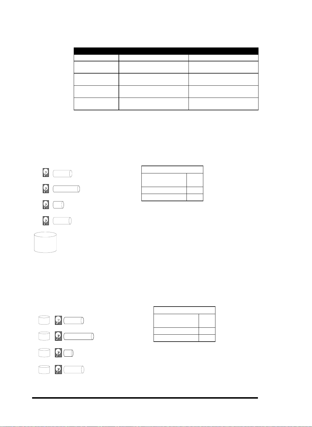
1.2 Logical Volume
What is a logical volume?
The concept of a logical volume is very similar to that of a logical
drive. A logical volume is the combination of one or several logica l
drives. These logical drives are combined into a larger capacity
using the RAID 0 method (striping). When data is written to a
logical volume, it is first broken into data segments and then striped
across different logical drives in a logical volume. Each logical drive
Functional Description
1-1
Page 24

then distributes data segments to its member drives according to the
specific RAID level it is composed of.
The member logical drives can be composed of the same RAID level
or each of a different RAID level. A logical volume ca n be divided
into a maximum of 64 partitions. Dur ing operation, the host sees a
non-partitioned logical volume or a pa rtition of a logical volume as
one single physical drive.
1.3 RAID Levels
RAID stands for Redundant Array of Independent Disks. Using a
RAID storage subsystem has the following advantages:
• Provides disk spanning by weaving all connected drives into
one single volume.
• Increases disk access speed by breaking data into several blocks
when reading/writing to several drives in parallel. With RA ID,
storage speed increases as more drives are added as the channel
bus allows.
• Provides fault-tolerance by mirr or ing or parity operation.
1-2
What are the RAID levels?
Table 1 - 1 RAID Levels
RAID Level Description Capacity Data Availability
NRAID
RAID 0
RAID 1 (0+1)
RAID 3
RAID 5
RAID 10
(Logical Volume)
RAID 30
(Logical Volume)
RAID 50
(Logical Volume)
NOTE: Drives on different channels can be included in a logical
drive and logical drives of different RAID levels can be used to
Non-RAID N
Disk Striping N ==NRAID
Mirroring Plus Striping (if
N>1)
Striping with Parity on
dedicated disk
Striping with interspersed
parity
Striping with RAID 1
logical drives
Striping with RAID 3
logical drives
Striping with RAID 5
logical drives
N/2 >>NRAID
==RAID 5
N-1 >>NRAID
==RAID 5
N-1 >>NRAID
==RAID 5
/ >>NRAID
>>RAID 5
/ >>NRAID
>>RAID 5
/ >>NRAID
>>RAID 5
Infortrend
Page 25
configure a logical volume. There are more combinations than
RAID 10, 30, and 50.
RAID Level Performance Sequential Performance Random
NRAID
RAID 0
RAID 1 (0+1)
RAID 3
RAID 5
NRAID
Disk Spanning
Figure 1 - 2 NRAID
Drive Drive
R: Highest
W: Highest
R: High
W: Medium
R: High
W: Medium
R: High
W: Medium
R: High
W: Highest
R: Medium
W: Low
R: Medium
W: Low
R: High
W: Low
2 GB Ha rd Drive
3 GB Ha rd Drive
1 GB Ha rd Drive
2 GB Ha rd Drive
2 + 3 + 1 + 2 = 8 G B
Logical Drive
Figure 1 - 3 JBOD
2 GB
3 GB
NRAID stands for Non-RAID. The capacity of all
the drives is combined to become one logical
drive (no block striping). In other words, the
capacity of the logical drive is the total capacity of
the physical drives. NRAID does not provide
data redundancy.
JBOD
Single Drive Control
2 GB Har d Dr iv e
3 GB Har d Dr iv e
NRAID
Minimum
1
Disks required
Capacity N
Redundancy No
JBOD
Minimum
Disks required
Capacity 1
Redundancy No
1
1 GB
2 GB
1 GB Har d Dr iv e
Functional Description
2 GB Har d Dr iv e
JBOD stands for Just a Bunch of Drives. The
controller treats each drive as a stand-alone
disk, therefore each drive is an independent
logical drive. JBOD does not provide data
redundancy.
1-3
Page 26
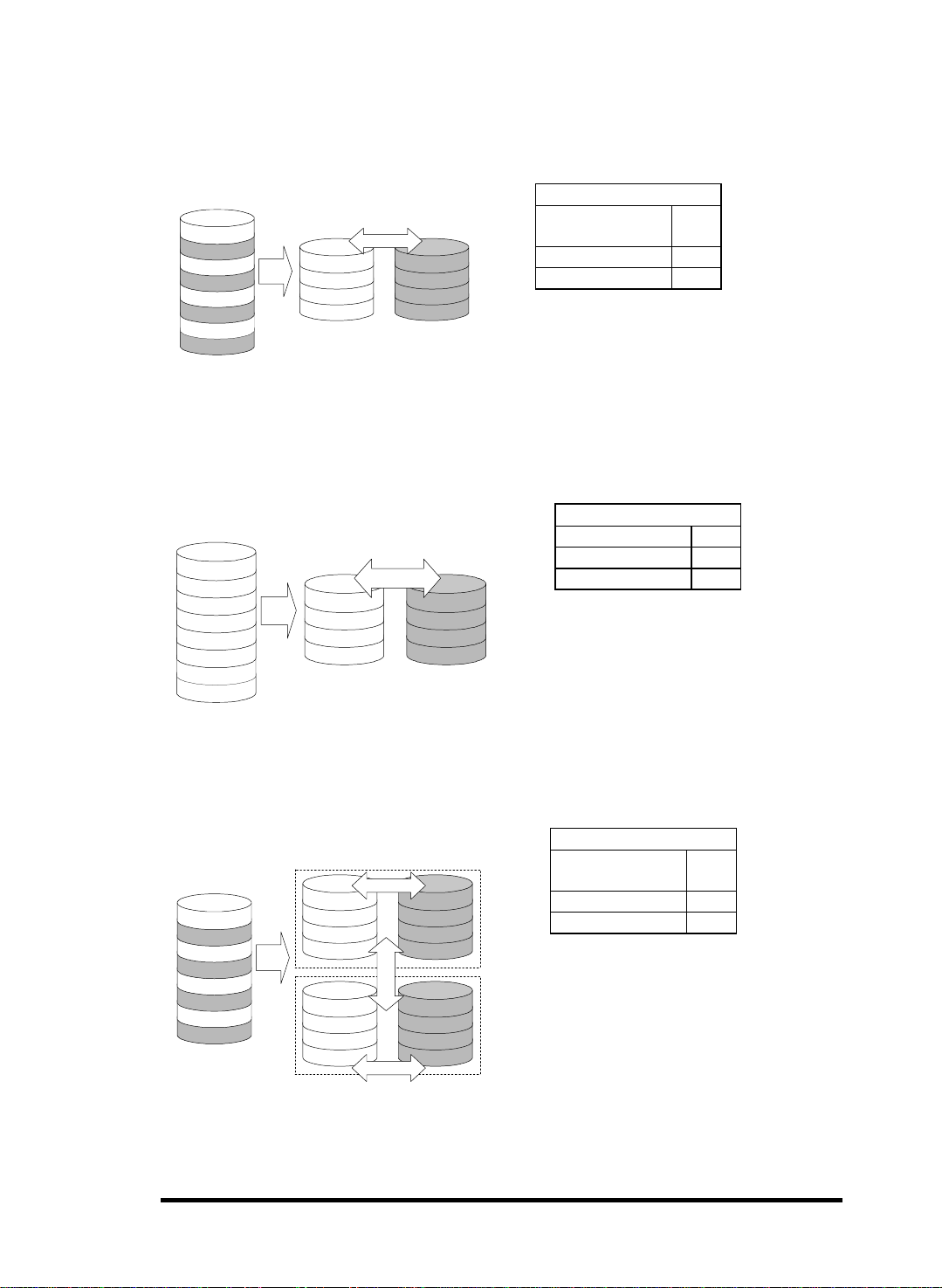
g
RAID 0
Disk Striping
Figure 1 - 4 RAID 0
Block 1
Block 2
Block 3
Block 4
Block 5
Block 6
Block 7
Block 8
Block 1
Block 3
Block 5
Block 7
RAID 1
Disk Mirroring
Figure 1 - 5 RAID 1
Block 2
Block 4
Block 6
Block 8
RAID 0
Minimum
2
Disks required
Capacity N
Redundancy No
RAID 0 provides the highest performance
but no redundancy. Data in the logical
drive is striped (distributed) across several
physical drives.
Logical Drive
Block 1
Block 2
Block 3
Block 4
Block 5
Block 6
Block 7
Block 8
Physical Disks
Block 1
Block 2
Block 3
Block 4
RAID (0+1)
Disk Striping with Mirroring
Figure 1 - 6 RAID (0+1)
Physical Disks
Logical Drive
Block 1
Block 1
Block 2
Block 3
Block 4
Block 5
Block 6
Block 7
Block 8
.
.
Block 3
Block 5
Block 7
.
.
Mirror 1
Mirror 3
Mirror 5
Mirror 7
.
.
Mirrorin
Striping
Mirror
Striping
Mirror 1
Mirror 2
Mirror 3
Mirror 4
Block 2
Block 4
Block 6
Block 8
.
.
Mirror 2
Mirror 4
Mirror 6
Mirror 8
.
.
RAID 1
Disks required 2
Capacity N/2
Redundancy Yes
RAID 1 mirrors the data stored in one
hard drive to another. RAID 1 can only
be performed with two hard drives. If
there are more than two hard drives,
RAID (0+1) will be performed
automatically.
RAID (0+1)
Minimum
4
Disks required
Capacity N/2
Redundancy Yes
RAID (0+1) combines RA ID 0 a nd RA ID 1 Mirroring and Striping. RAID (0+1) allows
multiple drive failure because of the full
redundancy of the hard drives. If there are
more than two hard drives assigned to
perform RAID 1, RAID (0+1) will be
automatically applied.
1-4
Infortrend
Page 27
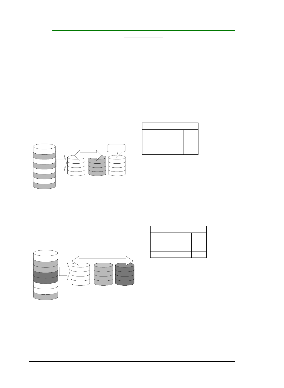
y
IMPORTANT!
•
“RAID (0+1)” will not appear in the list of RAID levels supported by th e
controller. If you wish to perform RAID 1, the controller will determine
whether to perform RAID 1 or RAID (0+1). This will depend on the
number of drives that has been selected for the logical d rive.
RAID 3
Disk Striping with Dedicated Parity Disk
Figure 1 - 7 RAID 3
Logical Drive
Block 1
Block 2
Block 3
Block 4
Block 5
Block 6
Block 7
Block 8
.
.
Block 1
Block 3
Block 5
Block 7
Ph
Striping
.
.
sical Disks
Block 2
Block 4
Block 6
Block 8
.
.
RAID 5
Striping with Interspersed Parity
Figure 1 - 8 RAID 5
Logical Drive Physical Disks
Block 1
Block 2
Block 3
Block 4
Block 5
Block 6
Block 7
Block 8
.
.
Striping + non-dedicated Parity
Block 1
Parity (3,4)
Block 6
Block 7
.
.
Block 2
Block 3
Parity (5,6)
Block 8
.
.
Dedicated
Parity
Parity (1,2)
Parity (3,4)
Parity (5,6)
Parity (7,8)
.
.
Parity (1,2)
Parity (7,8)
RAID 3
Minimum
3
Disks required
Capacity N-1
Redundancy Yes
RAID 3 performs Block Striping with
Dedicated Parity. One drive member is
dedicated to storing the parity data. When
a drive member fails, the controller can
recover/regenerate the lost data of the
failed drive from the dedicated parity
drive.
RAID 5
Minimum
3
Disks required
Capacity N-1
Redundancy Yes
RAID 5 is similar to RAID 3 but the
Block 4
Block 5
.
.
parity data is not stored in one
dedicated hard drive. Parity
information is interspersed across the
drive array. In the event of a failure, the
controller can recover/regenerate the
lost data of the failed drive from the
other surviving drives.
RAID 30 an RAID 50 are implemented as logical volumes,
please refer to the proceeding discussions for more details.
Functional Description
1-5
Page 28
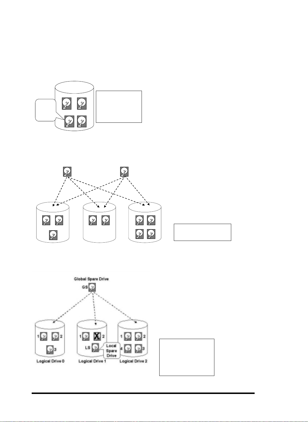
1.4 Spare Drives
Global and Local Spare Drives
Figure 1 - 9 Local (Dedicated) Spare
When one member
Local
Spare
Drive
12
X
LS
Logical Drive
drive fails, the Local
Spare Drive joins the
logical drive and
automatically starts
to rebuild.
3
Local Spare Drive is a standby drive
assigned to serve one specified logical
drive. When a member drive of this
specified logical drive fails, the Local
Spare Drive becomes a member drive
and automatically starts to rebuild.
Figure 1 - 10 Global Spare
Global Spare Drive
GS
12
3
Logical Drive 0
12
Logical Drive 1
Global Spare Drive
GS
Logical Drive 2
Figure 1 - 11 Global Spare Rebuild
Global Spare Drive not only
serves one specified logical
drive. When a member drive
from any of the logical drive
fails, the Global Spare Drive will
join that logical drive and
automatically starts to rebuild.
12
4
3
Global Spare Drives serve
any logical drive.
The external RAID controllers provide
both Local Spare Drive and Global
Spare Drive functions. On certain
occasions, applying these two
functions together will better fit
various needs. Take note though that
the Local Spare Drive always has
higher priority than the Global Spare
Drive.
1-6
When a member drive from
any logical drive fails, the
Global Spare Drive joins
that logical drive and
automatically starts to
rebuild.
Functional Description
Page 29
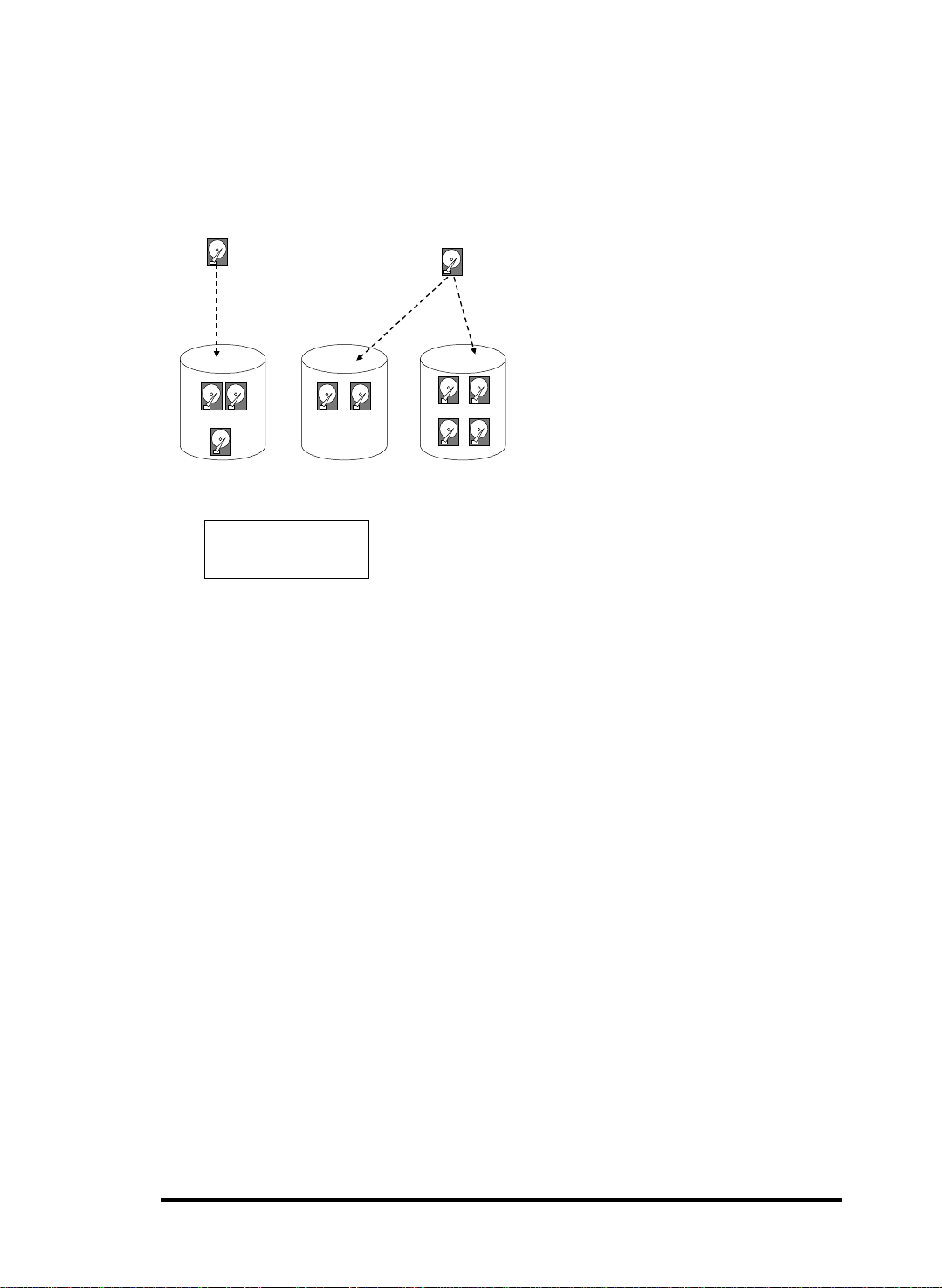
In the example shown below, the member of Logical Drive 0 are 9
GB drives, and the members in Logical Drives 1 and 2 are 4 GB
drives.
Figure 1 - 12 Mixing Local and Global Spares
Local Spare Drive
LS
(9GB)
12
(9GB)(9GB)
3
(9GB)
Logical Drive 0
A Local Spare always has
higher priority than a
Global Spare.
Global Sp ar e D r ive
GS
12
(4GB) (4GB)
Logical Drive 1
It is not possible for the 4 GB Global
Spare Drive to join Logical Drive 0
(4GB)
because of its insufficient capacity.
However, using a 9GB drive as the
Global Spare drive for a failed drive that
comes from Logical Drive 1 or 2 will
bring huge amount of excess capacity
since these logical drives require 4 GB
12
(4GB) (4GB)
4
(4GB) (4GB)
Logical Drive 2
only. In the diagram below, the 9 GB
Local Spare Drive will aid Logical Drive
3
0 once a drive in this logical drive f ails. If
the failed drive is in Logical Drive 1 or 2,
the 4 GB Global Spare drive will
immediately give aid to the failed drive.
Infortrend
1-7
Page 30
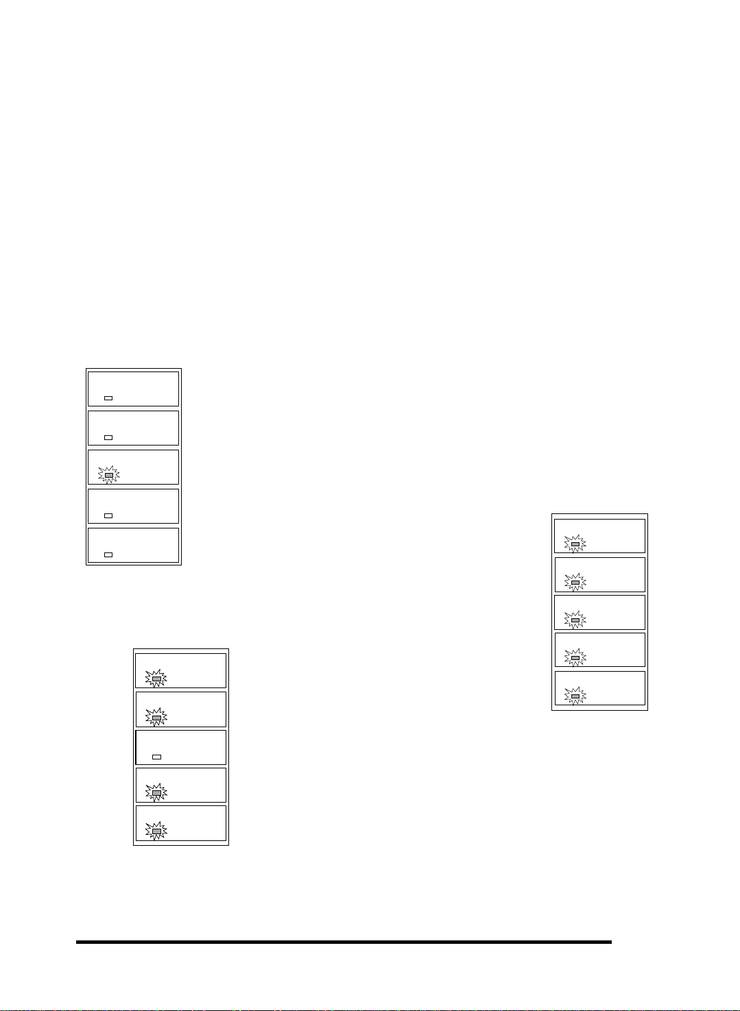
1.5 Identifying Drives
Assuming there is a failed drive in the RAID 5 logical drive, make it
a point to replace the failed drive with a new, healthy drive to keep
the logical drive working.
If, when trying to remove a failed drive you mistakenly remove
the wrong drive, you will no longer be able to access the logical
drive because you have inadequately failed another drive.
To prevent this from happening, the controller provides an easy way
to identify the faulty drive. By forcing certain drive LEDs to light
for a configurable period of time, the faulty drive can be identified,
and thus reducing the chance of removing the wrong drive. This
function is especially helpful in an installation site operating with
hundreds of drives.
R/W LED
Flash Selected SCSI Drive
R/W LED
LED Steadily ON
The Read/Write LED of the drive you selected will light steadily
for a configurable period of time, from 1 to 999 seconds.
R/W LED
R/W LED
LED
LED
LED
R/W
LED
LED
Flash All SCSI Drives
The Read/Write LEDs of all connected drives will
light for a configurable period of time. If the LED of
the defective drive did not light on the “Flash
Selected SCSI Drive” function, use “Flash All SCSI
Drives” to verify the fault. If the “Flash All SCSI
Drives” function is executed, and the defective drive’s
LED still does not respond, it can be a drive tray
problem or the drive is dead.
LED Steadil y ON
LED Steadil y ON
LED Steadil y ON
LED Steadil y ON
LED Steadil y ON
Flash All but Selected Drives
Except the selected drive, the Read/Write LEDs of all
connected drives will light for a configurable period of time ra nging
from 1 to 999 seconds. If an administrator can not be sure of the
exact location of specific drive, this function will help to indicate
where it is. This can prevent removal of the wrong drive when a
drive fails and is about to be replaced.
The drive identifying function can be selected from “Main
Menu”/”View and Edit SCSI Drives”/”Identify SCSI Drives.”
Functional Description
1-8
Page 31

1.6 Rebuild
Automatic Rebuild and Manual Rebuild
1. Automatic Rebuild
Figure 1 - 13 Automatic Rebuild
One member drive
fails in logical drive
Waiting for spare
drive to be added
or manual rebuild
Rebuild with Spare:
Any
local spare drive
assigned to logical
drive?
No
Any
global spare drive
assigned to logical
drive?
No
No
“Periodic
Auto-Detect Failure
Drive Swap Check Time”
enabled?
Yes
Has the
failed drive been
swapped?
Keep detecting if drive
has been swapped or
spare drive has been
No
added
When a member drive in a logical drive
Yes
Yes
Yes
Rebuild using the
local spare drive
Rebuild using the
global spare drive
Rebuild using the
swapped drive
fails, the controller will first examine whether there is a Local Spare
Drive assigned to this logical drive. If yes, rebuild is automatically
started.
If there is no Local Spare available, the controller will search for a
Global Spare. If there is a Global Spare, rebuild automatically
begins using the Global Spare.
1-9
Failed Drive Swap Detect:
If neither Local Spare Drive nor
Global Spare Drive is available, and the "Periodic Auto-Detect
Failure Drive Swap Check Time" is "Disabled," the controller will not
attempt to rebuild unless the user applies a forced-manual rebuild.
When the "Periodic Auto-Detect Failure Drive Swap Check Time" is
"Enabled" (i.e., a check time interval has been selected), the
controller will detect whether a faulty drive has been swapped (by
checking the failed drive's channel/ID). Once the failed drive has
been replaced by a healthy drive, the rebuild will begin
immediately.
Infortrend
Page 32

If the failed drive is not swapped but a local spare is added to the
p
logical drive, rebuild will begin with the spare.
If the S.M.A.R.T. function is enabled on drives and the reaction
scheme is selected for securing data on a failing drive, spare will
also be used for restoring data. Please refer to Chapter 9, Advanced
Functions, for more details.
2. Manual Rebuild
When a user applies forced-manual rebuild, the controller will f irst
examine whether there is any Local Spare assigned to the logical
drive. If yes, it will automatically start to rebuild.
If there is no Local Spare available, the controller will search for a
Global Spare. If there is a Global Spare, logical drive rebuild will be
automatically conducted.
Figure 1 - 14 Manual Rebuild
User applies
forced-manual
Any
Local Spare Drive
assigned to this
logical drive?
No
Any
Global Spare Drive
assigned to this
logical drive?
No
Has the failed drive
laced?
been re
No
Wait for
manual rebuild
Yes
Yes
Yes
Rebuild using the
Local Spare Drive
Rebuild using the
Global Spare Drive
Rebuild using the
replaced drive
I
If none of the spares are available, the controller will examine the
SCSI channel and ID of the failed drive. Once the failed drive has
been replaced by a healthy one, it starts to rebuild using the new
drive. If there is no available drive for rebuilding, the controller will
not attempt to rebuild until the user applies another forced-manual
rebuild.
Functional Description
1-10
Page 33

3. Concurrent Rebuild in RAID (0+1)
RAID (0+1) allows multiple drive failures and rebuild to be
concurrently conducted on more than one of its members. Drives
newly swapped must be scanned and set as Local Spares. These
drives will be used for rebuild at the same time (you do not need to
repeat the rebuild process for each member drive).
1-11
Infortrend
Page 34

1.7 Logical Volume (Multi-Level RAID)
What is a logical volume?
Figure 1 - 15 Logical Volume
…….
…….
…….
…….
…….
…….
Logical
Volume
Logical
Drive
…..
Logical
Drive
…..
Logical
Drive
…..
Physical Drive s
Physical Drive s
Physical Drive s
A logical volume is a combination of RAID 0 (Striping) and other
RAID levels. Data written to a logical volume is first broken into
smaller data segments and striped across different logical drives in a
logical volume. Each logical drive then distributes data segments to
its member drives according to its mirroring, parity, or striping
scheme. A logical volume can be divided into a maximum of eight
partitions. During normal operation, the host sees a non- partitioned
logical volume or a partition of a partitioned logical volume a s one
single physical drive.
The benefits of using a logical volume have been achieved by:
Extending the MTBF (mean time between failure) by using more
1.
redundancy drives (spare drives).
Decreasing the time to rebuild and reducing the chance of data
2.
loss by simultaneous drive failures because drives are included
in different drive groups using a multi-level logical structure.
Avoiding the chance of data loss by channel bus failure with
3.
flexible drive deployment.
As diagramed below, numerous drives can be included in a logical
drive, and one of them is used f or redundancy. By grouping these
drives into several logical drives, and then into a logical volume,
chance of failing two drives in a logical unit is greatly reduced. Each
logical drive can have one or more local spares. A failed drive can
be immediately replaced by a local spare, reducing the risk of losing
data if another should fa il soon afterwards.
Functional Description
1-12
Page 35

Figure 1 - 16 Logical Drive Composed of 24 Drives
RAID 5 Logical Drive
24 drives, 1 redundancy drive
Configuration A - One logical drive with all 24 drives
As illustrated above, Configuration A is a RAID 5 logical drive
consisting of 24 physical drives. Configuration B is a logica l volume
made of four RAID 5 logical drives.
Figure 1 - 17 Logical Volume with 4 Logical Drives
1-13
Configuration B can help to reduce the chance of encountering
points of failure:
a) Higher Redundancy: Configuration A has one dedicated spare,
while Configuration B allows the configuration of four spares. In
Configuration B, the risk of simultaneous drive failure in a logical
drive is significantly reduced than in Configuration A. The total
array capacity is comparatively smaller by the use of spares.
b) Less Rebuild Time: The time during rebuild is a time of hazard.
For example, a RAID 5 logical drive can only withstand single d rive
failure, if another drive fails during the rebuild process, data will be
lost. The time span for rebuilding a faulty drive should be
Infortrend
Page 36

minimized to reduce the possibility of having two drives to fail at
the same time.
Configuration A is a large logical drive and takes a long time to
rebuild. All members will be involved during the rebuild process.
In Configuration B, the time span is shorter beca use only 6 member s
will participate when rebuilding any of the logical drives.
c) Channel Failure Protection: Channel failure may sometimes
result from absurd matters like a cable failure. A channel failure
will cause multiple drives to fail at the same time and inevitably
lead to a fatal failure. Using a logical volume with drives coming
from different drive channels can get around this point of failure.
Figure 1 - 18 Logi cal Volume with Drives on Different
Channels
CH4
CH5
CH1
CH2
CH3
CH6
Functional Description
RAID 5
Logical
Drive
RAID 5
Logical
Logical
Volume
Logical Volume
24 drives, 4 redundancy drive
Configuration C - One logical volume with 4 logical drives
Drive
RAID 5
Logical
Drive
RAID 5
Logical
Drive
CH1/ID0
CH1/ID1
CH1/ID2
CH1/ID3
CH2/ID0
CH2/ID1
CH2/ID2
CH2/ID3
CH3/ID0
CH3/ID1
CH3/ID2
CH3/ID3
CH4/ID0
CH4/ID1
CH4/ID2
CH4/ID3
CH5/ID0
CH5/ID1
CH5/ID2
CH5/ID3
CH6/ID0
CH6/ID1
CH6/ID2
CH6/ID3
As illustrated above, should one of the drive channels fail, each
logical drive loses one of its members. Logical drives still have the
chance to rebuild its members. Data remains intact and the rebuild
can be performed after the failed channel is recovered. No access
interruptions to the logical volume will be experienced from the host
side.
Spare drives assigned to a logical volume?
A Local Spare can not be assigned to a L ogical Volume. If a drive
fails, it fails as a member of a logical drive; theref ore, the controller
allows Local Spare's assignment to logical drives rather than logical
volumes.
1-14
Page 37

Limitations:
The logical volume can not have any logical drive stated as "fatal
failed.” If there is any failed drive in any of its member logical
drives, controller will start to rebuild that logical drive. Should a ny
of the member logical drives fail fatally, the logical volume fails
fatally and data will not be accessible.
To avoid a logical volume failure:
Logical drives as members to a logical volume should be
1.
configured in RAID levels that provide redundancy - RAID
levels 1 (0+1), 3, or 5.
Rebuild the logical drive as soon as possible whenever a drive
2.
failure occurs. Use of local spares is recommended.
A logical drive should be composed of physical drives from
3.
different drive channels. Compose the logical drive with drives
from different drive channels to avoid the fatal loss of data
caused by bus failure.
Partitioning - partitioning the logical drive or partitioning the logical volume?
Once a logical drive has been divided into partitions, the logical
drive can no longer be used as a member of a logical volume. The
members of a logical volume should have one partition only with
the entire capacity.
If you want to use a partitioned logical drive for a logical volume,
delete the other partitions in this logical drive until there remains
one partition only with the entire capacity. Mind that deleting the
partition of the logical drive will also destroy all data. Da ta should
be backed up before making partition configuration.
When a logical drive is used as a member to a logica l volume, this
logical drive can no longer be partitioned in “View a nd Edit L ogical
Drives.” Instead, the Logical Volume can be partitioned into 8 in
“View and Edit Logical Volume.”
The procedure for partitioning a logical volume is the same as that
for partitioning a logical drive. After the logical volume has been
partitioned, map each partition to a host ID/LUN to make the
partitions available as individual drives.
1-15
Infortrend
Page 38

Different write policies within a logical volume?
As members of a logical volume, all logical drives will be forced to adopt a
consistent write policy. Whenever the write policy of a logical volume is
changed, for example, the corresponding setting in its members will also be
changed.
RAID expansion with logical volume?
The Logical Volume can also be expanded using the RAID
expansion function. The concept of expanding a logical volume is
similar to that of expanding a logical drive. To perform RAID
expansion on a logical drive, replace each member physical drive
with a drive of larger capacity or add a new drive, then perform
logical drive expansion to utilize the newly-added capacity. For
information about RAID expansion, please refer to Chapter 9
"Advanced Configurations."
To perform RAID expansion on a logical volume, expand each
member logical drive, then perform “RAID Expansion” on the
logical volume.
Steps to expand a Logical Volume:
1. Expand each member logical drive.
2. Expand the logical volume.
3. M ap the newly-added capacity ( in the form of a new par tition)
to a host LUN.
IMPORTANT!
•
If a logical unit has already been partitioned, and you wish to expand its
capacity, the added capacity will be appended to the last partition. You
will not be able to proceed with expansion using firmware version earlier
than 3.27 when the unit already has 8 partitions.
•
Unless you move your data and merge two of the partit ions, you will be
not allowed to expand your logical volume. This is a precautionary
limitation on logical unit expansion.
Different controller settings using logical volume?
Redundant Controller:
Without logical volume - logical drives can be assigned to the
primary or the secondary controller. The host I/Os directed to a
logical drive will be managed by the controller which owns the
Functional Description
1-16
Page 39

logical drive. If a controller fails, the host I/Os originally assigned
to the failed controller will be taken over by the existing controller.
When the controller fails back (failed controller being replaced by a
new one), logical drives will be returned to the replacement
controller in its original configuration.
With logical volume - logical volumes can also be assigned to
different controllers. The only difference is logical volumes will be
used as base units when shifting control during controller failure.
A logical volume with logical drives of different levels?
Multi-level RAID systems
1.
RAID (0+1)
controllers. It brings the benefits of RAID 1 (high availability)
and RAID 0 (enhanced I/O performance through striping).
Simply choose multiple drives (more than two) to compose a
RAID 1 logical drive, RAID (0+1) will be automatically
implemented.
2.
RAID (3+0)
implementation by its own rights. A logical volume is a logical
composition which stripes data across several logical drives (the
RAID 0 method). A logical volume with several RAID 3
members can be considered as a RAID (3+0), or RAID 53 as
defined in "The RAID Book" (from The RAID Advisory Board).
3.
RAID (5+0)
- this is a standard feature of Infortrend RAID
- a logical volume is a multi-level RAID
- a logical volume with several RAID 5 members.
1-17
Infortrend
Page 40

Chapter
Chapter
ChapterChapter
2
2
22
RAID Planning
This chapter summarizes the procedures and provides some useful
tools for first-time configuration:
2.1 Considerations: things you should know before setting
up
2.2 Configuring the
Array:
2.3 Operation Theory: the theory behind data bus and system
2.4 Functional Table of
Contents
the most common configuration
procedure
drive mapping
a useful tool that helps you to quickly
locate a firmware function
2.1 Considerations
After you understand the basic ideas behind RAID levels, you may
still be wondering about how to begin. Here are the answers to
some questions that may help you through the decision making.
1. How many physical drives do you have ?
When initially creating the drive groups, you should know how
many drives you have in your RAID system or in the JBOD
attached to the RAID controlling unit.
2. How many drives on each drive channel?
The optimal system planning is always a compromise between
pros and cons. As a general rule, the number of drives you
should connect on each channel equals the data bus bandwidth
divided by the maximum transfer rate you can get from each of
your hard drives. Knowing the mechanical performance of
your hard drives can help to determine how many drives
should be connected over a drive c hannel.
Always use fast and large drives of the same capacity for your
disk array. A logical drive composed of a n adequate number of
RAID Planning
2-1
Page 41

larger drives can be more efficient than that of many but
smaller drives.
3. How many drives would you like to appear to the
host computer?
It must be decided what capacity will be included in a logical
configuration of drives, be it a logical drive or a logical volume.
A logical configuration of drives will appear to the host as a
single capacity volume.
You may compose a large logical volume consisting of drives
on different drive channels, and have it partitioned into smaller
partitions. Each partition will appear as an independent
capacity volume. In a perf ormance -oriented configur ation, you
may configure the same number of drives into several RAID 0
logical drives just to get the most out of the array performance.
4. What kind of host application?
The frequency of read/write activities can vary from one host
application to another. The application can be a SQL server,
Oracle server, Informix, or other data base server of a
transaction-based nature. Applications like video playback a nd
video post-production editing require read/write activities of
larger files coming in a sequential order.
Choose an appropriate RAID level for what is the most
important for a given application – capacity, availability, or
performance. Before cr eating your RAID, you need to choose
an optimization scheme and optimize each array/contr oller for
your application. Stripe size and write policy can be adjusted
on a per logical drive basis.
5. Dual loop, hub, or switch?
Unpredictable situations like a cable coming loose can cause
system down time. Fibre channel dual loop or r edundant data
paths using flexible LUN mapping method can guarantee there
is no single point of failure. The use of Fibre channel hub or
switch makes cabling and topology more flexible. Change the
channel mode, connection type, a nd other assoc iated se ttings to
adjust the controller to your demands.
6.
2-2
Infortrend
Page 42

Optimization Mode
Figure 2 - 1 Optimi zat ion Setting
You should select an optimization scheme best suite d to your
applications before configuring a RAID array. Once the
optimization mode is selected, it will be applied to all arrays
managed by the RAID controller.
Two options are available: Sequential I/Os and Random I/Os.
You may refer to the “Caching Parameters” section in Chapter
5 and Chapter 7 for the stripe size variables and its relations
with RAID levels.
Numerous controller parameters are tuned for each
optimization mode. Although stripe size c an be adjusted on a
per logical drive basis, users are not encouraged to make a
change to the default values.
For example, smaller stripe sizes are ideal for I/Os that are
transaction-based and randomly accessed. However, using the
wrong stripe size can cause problems. When an array of the
4KB stripe size receives files of 128KB size, each drive will have
to write many more times to store data fragments of the size of
4KB.
Unlike the previous firmware versions, controller optimization
mode can be changed without changing the array stripe size.
The default values in optimization modes guarantee the
optimal performance for most applications. C onsult Table 2-2
for all the controller parameters that are related to system
performance and fault- tolerance.
7. What RAID level?
Different RAID levels provide varying levels of performance
and fault tolerance.
RAID Planning
2-3
Page 43

Table 2 - 1 RAID Levels
RAID Level Description Capacity Data Availability
NRAID Non-RAID N N/A
RAID 0 Disk Striping N ==NRAID
RAID 1 (0+1) Mirroring Plus Striping (if N>1) N/2 >>NRAID
==RAID 5
RAID 3 Striping with Parity on
dedicated disk
RAID 5 Striping with interspersed
parity
Logical
Volume
RAID Level Performance Sequential Performance Random
NRAID Drive Drive
RAID 0 R: Highest
RAID 1 (0+1) R: High
RAID 3 R: High
RAID 5 R: High
Logical Volume Depends on its members;
Striping one or more logical
drives of different RAID levels
W: Highest
W: Medium
W: Medium
W: Medium
see above
N-1 >>NRAID
==RAID 5
N-1 >>NRAID
==RAID 5
* Higher; depends
on its members
R: High
W: Highest
R: Medium
W: Low
R: Medium
W: Low
R: High
W: Low
Depends on its members
8. Any spare drives?
(Swap Drive Rebuild / Spare Drive Rebuild)
Spare drives allow for the unattended rebuilding of a failed
drive, heightening the degree of fault tolerance. If there is no
spare drive, data rebuild has to be manually initiated by
replacing a failed drive with a healthy one.
As is often ignored, a spare d rive (whethe r dedic ated or globa l)
must have a capacity no smaller than the members of a logical
drive.
9. Limitations?
Firmware 3.31 and above support 64-bit LBA. A maximum of
64TB capacity can be included in single logical drive.
Up to 128 members can be included in each logical drive.
Extreme array sizes can cause operational problems with
system backup and should be avoided.
2-4
Infortrend
Page 44

2.2
Configuring the Array:
2.2.1 Starting a RAID System
Here is a flowchart illustrating basic steps to be taken when
configuring a RAID system. Hardware installation should be
completed before any configuration takes place.
Figure 2 - 2 Array Configuration Process
Drives must be configured and the controller properly initialized
before a host computer can access the storage capacity.
1. Use the LCD panel, terminal program, or the RAIDWatch
manager to start configuring your array.
2. When powered on, the controller scans all the hard d rives that
are connected through the drive channels. If a hard drive is
connected after the controller completes initialization, use the
"Scan SCSI Drive" function to let the controller recognize its
presence.
3. Optimize controller's parameters for your applications.
4. Configure one or more logical drives to contain your hard drive s
based on the desired RAID level, and/or partition the logical
drive or logical volume into one or several partitions.
RAID Planning
2-5
Page 45

NOTE:
•
A "Logical Drive" is a set of drives grouped toget her to operate under a
given RAID level and it appears as a single contiguous volume. The
controller is capable of grouping drives into as many as 128 logical
drives, configured in the same or different RAID levels.
•
A total of 32 "Logic al Volumes" can be creat ed each from one or several
logical drives. A logical drive or logical volume can be divided into a
maximum of 64 "Partitions."
5. The next step is to make logical drives or storage partitions
available through the host ports. When associated with a host
ID or LUN number, each capacity volume appears as one
system drive. The host SCSI or Fibre adapter will recognize the
system drives after the host bus is re-initialized.
6. The last step is to save your configuration profile in the host
system drive or to the logical drives you created.
The controller is totally independent from host operating system.
Host operating system will not be able to tell whether the attached
storage is a physical hard drive or the virtual system drives created
by the RAID controller.
2-6
Infortrend
Page 46

2.3 Operation Theory
2.3.1 I/O Channel, SCSI ID, and LUN
Depending on the interface used by a RAID system, a SCSI drive
channel (SCSI bus) can connec t up to 15 drives ( excluding the RA ID
controller itself). A Fibre channel 125 drives in a loop. Each device
occupies one unique ID.
Figure 2 - 3 SCSI ID/LUNs
The figure on the left illustrates the idea of mapping a system
drive to host ID/LUN combinations. The host ID is like a
cabinet, and the drawers are the LUNs (LUN is short for Logical
Unit Number). Each cabinet (host ID) can have up to 32
drawers (LUNs). Data can be made av aila ble through one of the
LUNs of a host ID. Most host adapters treat a LU N like a nother
device.
2.3.2 Grouping Drives into an Array
Figure 2 - 4 Connecting Drives
The physical connection of a RAID controller should be similar to
the one shown above. Drives are conne cted through I/O paths that
have been designated as drive channels.
The next diagram shows two logical c onfigurations of drives and the
physical locations of its members. Using drives from different
channels can lower the risk of fatal failure if one of the drive
channels should fail. There is no limitation on the locations of
spares.
RAID Planning
2-7
Page 47

Figure 2 - 5 Physical locations of drive members
A drive can be assigned as the Local Spare Drive that serves one
specific logical drive, or as a Global Spare Drive that participates in
the rebuild of any logical drive. Spares automatica lly joins a logical
drive when a drive fails. Spares are not applicab le to logical drives
that have no data redundancy (NRAID and RAID 0).
Figure 2 - 6 Partitions in Logical Configurations
You may divide a logical drive or logical volume into partitions of
desired capacity, or use the entire capacity as single volume.
1. It is not a requirement to partition any logical configuration.
Partitioning helps to manage a massive capacity.
2. Note that a logical drive can not be includ ed in a logica l volume
if it has already been partitioned.
2-8
Infortrend
Page 48

2.3.3 Making Arrays Available to Hosts
Figure 2 - 7 Mapping Partitions to Host ID/LUNs
Host ID mapping is a process that associates a logical configuration
of drives with a host channel ID/LUN. To avail logical partitions on
host channel(s), map each par tition to a host ID or one of the LUNs
under host IDs. Each ID or LUN will appear to the host adapter as
one virtual hard drive.
There are alternatives in mapping for different purposes:
1. Mapping a logical configuration to IDs/LU Ns on different host
channels allows two host computers to access the same array.
This method is applicable when the array is shared in a
clustering backup.
2. Mapping partitions of an array to IDs/LUNs across separate
host channels can distribute workload over multiple data paths.
3. Mapping across separate host channels also helps to make use of
all bandwidth in a multi-path configuration. Firmware
automatically manages the process when one data path f ails a nd
the workload on the failed data path has to be shifted to the
existing data paths.
Figure 2 - 8 Mapping Partitions to LUNs under ID
RAID Planning
2-9
Page 49

2.4 Tunable Parameters
Fine-tune the controller and the array parameters for your host
applications. Although the factory defaults guarantee the optimize d
controller operation, you may refer to the table below to facilitate
tuning of your array. Some of the performance and fault-tolerance
settings may also be changed later during the preparation pr ocess of
your disk array.
Take this table as a check list and make sure you have each item set
to an appropriate value.
Table 2 - 2 Controller Parameter Settings
➀➀➀➀
➁➁➁➁
➂➂➂➂
Parameters that should be configured at the initial stage of system
configuration
Parameters that can be changed later
Non-critical
User-Defined
Parameters
Fault Management:
➀
Automatic Logical
Drive Rebuild - Spare
Drive
➀
S.M.A.R.T.
➂
Clone Failing Drive
➀
Rebuild Priority
➀
Verification on Write
➂
SDRAM ECC
➀
Event Notification
➀
System Events
Default Alternate Settings
Enabled when
Spare Drive is
available
Disabled Detect Only
Manual function Replace After Clone
Low (higher
priority requi re s
more system
resource)
Disabled On LD Initialization
Disabled Enabled
Reports to user
interface and
onboard alarm
System default Upper and Lower event triggering
RAID 1 + Local Spare
RAID 3 + Local Spare
RAID 5 + Local Spare
Global Spare
Perpetual Clo ne
Clone + Replace
Perpetual Clo ne
Low
Normal
Improved
High
On LD Rebuild
On Normal Drive Writes
Over Dial-out Modem
Over SNMP Trap
Over Java-Based Management
Software
thresholds configurable
2-10
Controller:
➀
Channel Mode
➀
Host and Drive channel IDs
➀
Controller Unique
Identifier
➁
Data rate
* Host, Drive, RCCOM, Drive +
Preset on
some
models
Auto Depends on problems solving
RCCOM
**
hex number from 0 to FFFFF (FW 3.25
and above)
RAID Planning
Page 50

➀
Date and time
➀
Time zone
Optimization Mode:
N/A
+ 8 hrs
➀
Write-back Cache
➀
Array stripe size
➀
Optimization for
Random/Sequential
➁
Array write policy
SCSI Parameters:
➀
Data Transfer Rate
➀
Maximum Tag Count
➀
Maximum Queued
I/O Count
➁
LUN’s per SCSI ID
➀
Periodic Drive Check
Time
➀
Periodic SAF-TE and
SES Device Check
Time
➀
Periodic Auto-Detect
Failure Drive Swap
Check Time
➀
Number of Host-LUN
Connection
➀
Tag per Host-LUN
Connection
➀
Wide Transfer
➀
Parity Check
Enabled Disabled
Related to controller general
setting
Sequential Either (sequential for LD larger than
512MB and can not be changed)
Related to controller general
setting
* Async. To 100.0MHz
32 1-128
32 32 to 1024
8Up to 32
Disabled Enabled
5 Disabled to 60 seconds
Disabled 5 to 60 seconds
32 1 to 1024
32 1 to 256
* Enabled/Disabled
Disabled Enabled
4KB to 256KB
W/B or W/T
Infortrend
Spin-Up Parameters:
➀
Motor Spin-Up
➀
Reset at Power-UP
➀
Initial Disk Access
Delay
Disabled Enabled
Enabled Disabled
* None to 75 seconds
Fibre Channel Parameters:
➀
Fibre Connection
Options
➀
Fibre Channel Dual-
Loop
➀
Host ID/WWN name
list
➀
LUN Filtering
➀
RCC through Fibre
channel
* Loop Only
Enabled Enabled by cabling
* User configurable
* Host Access Filter Control
* Dedicated or sharing drive channel(s)
Point-to-Point Only
Loop Preferred
Point-to-Point Preferred
Configurable - filter type - access
right - name
2-11
Page 51

Array Configuration:
➀
Disk reserved space
➁
Array assignment
➀
Array partitio ning
Others:
➂
Password
➂
LCD Display
Controller Name
256MB 64KB – backward compatible
Primary
controller
1Up to 64
N/A User-De fined; Password
N/A User-Defined
Secondary controller
Validation Timeout: 1 to Always
Check Configurable
RAID Planning
2-12
Page 52

Chapter
Chapter
ChapterChapter
3
3
33
Accessing the Array
through Serial Port and
Ethernet
3.1 RS-232C Serial Port
Infortrend’s controllers and subsystems can be configured via a PC
running a VT-100 terminal emulation program, or a VT-100
compatible terminal. RAID enclosures usually provide one or more
DB-9 RS-232C ports. Simply use an RS-232C cable to connect
between the controller/enclosure’s RS-232C port and the PC serial
(COM) port.
Make sure you use the included null modem (IFT-9011) to convert
the serial port signals. A null modem might have been provided
inside your enclosure. The Null Modem has the serial signals
swapped for connecting to a standa r d PC serial interface.
The following are guidelines on using the serial port:
• The serial port’s default is set at 38400 baud, 8 bit, 1 stop bit and
no parity. Use the COM1 serial port of the controller.
• In most ca ses, connecting RD, TD, and SG is enough to establish
the communication with a terminal.
• If you are using a PC as a terminal, any VT-100 terminal
emulation software will suffice. Microsoft
terminal emulation program as presented with the “(Hyper)
Terminal” icon in the Acce ssories window.
• For other details of connecting serial port, please refer to the
Hardware Manual that came with your controller.
®
Windows includes a
Out-of-Band via Serial Port and Ethernet
3-1
Page 53

3.1.1 Configuring RS-232C Connection via Front Panel
Take the following steps to change the baud rate using the front
panel keypad:
Press ENT for two seconds to enter the
Main Menu. Press ▼ or ▲ to select
"View and Edit Configuration ..", then
press ENT.
Select "Communication Parameters ..",
then press ENT.
Select "RS-232 Configuration ..", then
press ENT.
Select "COM1 Configuration ..", then
press ENT.
Select "Baud-rate 38400 ..", then press
ENT.
The baud rate default is 38400. If other
baud rate is preferred, press ▼ or ▲ to
select the baud rate, then press ENT for 2
seconds to confirm the selected baud
rate. Set identical baud rate to your
RAID array and your terminal computer.
View and Edit
Config Parms ↕
Communication
Parameters ..
RS-232C
Configuration ..
COM1
Configuration ..
Baud-rate 38400
..
Baud-rate 38400
Change to 19200?
3-2
• The following baud rates are available: 2400, 4800, 9600, 19200
and 38400.
• Terminal connection should work properly using the above
setting. You may check the following options in your COM port
configuration if you encounter problems:
1. “Comm Route Dir ..”: The communication route should be
configured as “direct to port” instead of “through PPP”.
2. “Term Emul. Enab ..”: Make sure the terminal function has
not been accidentally disabled.
Infortrend
Page 54

3.1.2 Starting RS-232C Terminal Emulation
The keys used when operating via the terminal are as follows:
←←←← →→→→ ↑↑↑↑ ↓↓↓↓
[Enter]
[Esc]
[Ctrl] [L]
To select options
To go to a submenu or to execute a selected option
To escape and go back to the previous menu
The controller will refresh the screen information
IMPORTANT!
•
If the RS-232C cable is connected while the controller is powered on, press
[Ctrl] [L] to refresh the screen information.
The initial screen appears when the controller finishes self-test and
is properly initialized. Use ↑↑↑↑ ↓↓↓↓ arrow keys to select terminal
emulation mode, then press [ENTER] to enter the Main Menu.
Choose a functional item from the ma in menu to begin configuring
your RAID.
Connecting Terminal
3-3
Page 55

3.2 Out-of-Band via Ethernet
The RAIDWatch manager software provides graphical interface to the
subsystem. Before you can access the RAID system using the software
manager, your must:
1. Create a reserved space on your array(s)
2. Set up the related TCP/IP configurations to enable the Ethernet
port and the http service
3. FTP RAIDWatch program files to the controller IP address
What Is the “Disk Reserved Space?”
RAIDWatch and Reserved Space:
•
There is no need to install the RAIDWatch program to your
management computer if you access the software using the controller
Ethernet port. In order to simplify the installation process, system
firmware already contains important software agents.
•
User’s configuration data and the manager’s main programs are kept in
a small section of disk space on each data drive. The segregated disk
space is called a “Disk Reserved Space.” When configuring a
logical drive, firmware automatically segregates a 256MB of
disk space from each of the member drives.
•
Because the manager’s main program is run from the reserved space on
drives, in the event of RAID controller failure, the manager interface
can “failover” to a counterpart controller. Operators’ access to the
system will not be interrupted.
3-4
Infortrend
Page 56

Other Concerns
Availability Concern:
For safety reason, it is better to create a reserved space on more than one
logical drive.
Whatever data is put into the reserved space, firmware will automatically
duplicate and distribute it to the reserved section on every data drive. Even
if one hard drive or one logical drive fails, an exact replica still resides on
other drives.
Web-Based Management
The controller firmware has embedded http server. Once properly
configured, the controller/subsystem’s Ethernet port behaves like an HTTP
server.
Requirements
1.
Controller/subsystem running
[3.25 onwards has embedded NPC (Notification Processing Center)
support]
Firmware revision 3.21 and above
2. Management Station:
Pentium or above compatible (or equivalent PC) running Windows NT
4/Windows 2000; Solaris 7 & 8 (SPARC, x86); AIX 4.3; or Red Hat
Linux 6.1 (kerne l v2.2.xx); Red H at 7/8, SUSE 7, WIN95/98 , or
Windows Me/XP
3.
Standard Web Browser.
4. A management station (computer) accessing RAIDWatch manager must
support:
- TCP/IP
Java Runtime:
-
it can be downloaded from SUN Microsystems’ web site.
a package is bundled with RAIDWatch installer or
5. A static IP address
3.2.1 Connecting Ethernet Port:
Use a LAN cable to connect the Ethernet port(s) on the subsystem’s RAID
controller unit(s). Use only shielded cable to avoid radiated emissions that
may cause interruptions. Connect the cable between controller’s LAN port
and a LAN port from your local network.
Connecting Terminal
3-5
Page 57

3.2.2 Configuring the Controller
To prepare the controller for using the RAIDWatch manager, do the
following:
1. Use a Terminal Emulator to Begin Configuration
Connect the subsystem’s serial port to a PC running a VT-100 terminal
emulation program or a VT -100 compatible terminal.
Make sure the included Null Modem is already attached to enclosure serial
port or the host computer’s COM port. The Null Modem converts the
serial signals for connecting to a standard PC serial interface. For more
details, please refer to the descriptions above in section 3.1.
2. Create a Reserved Space on Drives
3-6
Create one or more logical drives and the reserved space option will be
automatically available. The default size is 256MB, and it is recommended
to keep it as is. A reserved disk space will be formatted on every member
drives.
If you delete a logical drive later, the reserved space will remain intact.
Unless you manually remove the reserved space, data kept in it will be
unaffected. These drives can later be used to create a new logical drive
without making additional changes.
Infortrend
Page 58

When formatted, a meta-filesystem is created on the 256MB reserved
space. A drive configured with a reserved space will be stated as a
“formatted drive.”
3. Assign an IP Address to Ethernet Port:
Assign an IP address to the controller Ethernet port and specify the Net
Mask and gateway values. Power off your system and then power on again
for the configuration to take effect.
Select "View and Edit Configuration Parameters" from the main menu.
Select "Communication Parameters" -> "Internet Protocol (TCP/IP)" ->
press [ENTER] on the chip hardware address -> and then select "Set IP
Address."
Provide the IP address, NetMask, and Gateway values accordingly.
PING the IP address from your management computer to make sur e the link
is up and running.
4. FTP Manager Programs to the Controller IP
There are several RAIDWatch programs that need to be FTP’ed to the
controller IP address.
1. Necessary program files can be found in a zip file (GUI.zip) in the CD-
2. Open a DOS prompt. You may use an FTP program to complete the
Connecting Terminal
Address
ROM that came with your machine. Unzip “grem.htm”, “grem.jar”,
“grm.htm”, and “grm.jar” to your PC. Files are available in the
following directory: X:\Java where X is the CD-ROM letter.
same process. Key in “ftp xx.xx.xx.xx” (controller IP address).
3-7
Page 59

3. Login as “root” and there is no password for the first login. Press Enter
to skip password entry.
4. Use the “put” command to transfer the following files:
put grm.htm
put grm.jar
put grem.htm
put grem.jar
5. Proceed to install Java Run-time environment from the CD (If the
management station is a P4-based computer, it is required to install
Java JRE version1.3.1).
6. Reset the RAID subsystem using the Reset command for the
configuration to take effect.
5. Starting the Manager:
Start your web browser and enter the IP address assigned to the
controller followed by “grm.htm” as your URL (e.g.,
http://xx.xx.xx.xx/grm.htm).
Enter the IP address followed by “grem.htm” to start Event Monitor.
3-8
Infortrend
Page 60

3.2.3 NPC Onboard
NPC is short for Notification Processing Center, a sub-module for
use with system event notification.
To activate the NPC module, do the following:
1. Create an NPC configuration file (in a simple text file format)
using a text editor program.
2. Save it in the name of “agent.ini”
3. FTP it to the controller IP address, and then reset the controller
for the configuration to take effect.
Listed below is the sample configuration. Specify your
configuration using simple defining para me ters as shown below.
[SNMP_TRAP]
ENABLED=0 (1=on; 0=off)
SEVERITY=1
COMMUNITY=public
RECEIVER1=XXX.XXX.XXX.XXX,2 ("2" specifies the level of
events to be received by this receiver)
[EMAIL]
ENABLED=0
SEVERITY=1
SUBJECT=Event Message
SENDER_MAIL_BOX=XXXX@XXXXX.XXX
SMTP_SERVER=XXX.XXX.XXX.XXX
RECEIVER1=XXXX@XXXXX.XXX,3
RECEIVER2=XXXX@XXXXX.XXX,1
RECEIVER3=XXXX@XXXXX.XXX,2
RECEIVER4=XXXX@XXXXX.XXX,1
[BROADCAST]
ENABLED=0
SEVERITY=1
RECEIVER=XXX.XXX.XXX.XXX, 1
RECEIVER=XXX.XXX.XXX.XXX, 1
The configuration file is comprised of three maj or sections: SNMP, Email
and Broadcast. Each notifying method can be separately enabled or
disabled.
Connecting Terminal
NOTE:
NPC will be automatically activated if any of the notifier settings
(email, SNMP, or broadcast) is set to “enabled.”
3-9
Page 61

The SNMP_TRAP section
[SNMP_TRAP] – section header
[ENABLED] – 1=enabled, 0=disabled (applies to this section only)
[SEVERITY] - level of severity of the messages to be received:
1. notification, 2. warning, 3. alert. “1” covers events of all levels. “3”
sends only the most serious events.)
[COMMUNITY] – SNMP community name of the destination/ receiver
[RECEIVER] – The IP address of the receiver computer. Add additional
lines to specify multiple receivers. Up to 4 receivers can be configured.
The EMAIL section
[EMAIL] – section header
[ENABLED] – 1=enabled, 0=disabled (applies to this section only)
[SEVERITY] - level of severity of the messages to be received:
notification, 2. warning, 3. alert. “1” covers events of all levels. “3” sends
only the most serious events.)
[SUBJECT] – add a topic to email. This can be used to specify the location
of the RAID system, if there are many.
[SENDER_MAIL_BOX] – a valid email address to be used as the “from”
part of the email message.
[SMTP_SERVER] – SMTP server used to send email. IP address only, do
not enter a host name here.
[RECEIVER#] – receiver’s email address. The receiver’s number followed
by an “=” mark, an email address, “comma,” and the number to specify the
message severity level.
* * * *
3-10
The BROADCAST section
[BROADCAST] – section header
[ENABLED] – 1=enabled, 0=disabled (applies to this section only)
[SEVERITY] – level of severity of the messages to be received:
1. notification, 2. warning, 3. alert. “1” covers events of all levels. “3”
only the most serious events will be broadcast.)
[RECEIVER#] – The IP address of the receiver computer. Add additional
lines to specify multiple receivers. Up to 4 receivers can be configured.
Infortrend
Page 62

Chapter
Chapter
ChapterChapter
4
4
44
LCD Screen Messages
4.1 The Initial Screen
Product Model
Firmware Version
SR2500 v3.**
Ready
Status/Data Transfer Indicator
Status/Data Transfer Indicator:
Ready There is at least one logical drive or logical volume
mapped to a host ID/LUN.
No Host
LUN
❚❚❚❚❚❚❚❚❚❚❚❚
No logical drive created or the logical drive has not
yet been mapped to any host ID/LUN.
Indicates data transfer. Each block indicates
256Kbytes of data throughput.
4.2 Quick Installation Screen
Quick Logical
Drive Install
¯
Press [ENT] to create a logical drive, the controller will start
initialization of one logical drive with all the connected SCSI drives
and automatically map the logical drive to L UN 0 of the first host
channel. The “Quick Installation” can only be performed when
there is no Logical Drive.
LCD Screen Messages
4-1
Page 63

4.3 Logical Drive Status
Logical Drive
LG0 RAID5 DRV=3
LG=0 RAID5 DRV=3
2021MB GD SB=1
2021MB GD SB=1
Logical Drive status
Logical Drive:
RAID level:
Drive numbers:
Logical Drive status:
XxxxMB The capacity of this logical drive.
SB=x Standby drives available to this logical
xxxxMB INITING The logical drive is now initializing.
xxxxMB INVALID For firmware version before 3.31:
The Logical Drive number.
The RAID level used in this logical drive
The number of physical drives included in
this configuration.
drive. Except the spares dedicated to other
logical configurations, all spare drive(s) will
be counted in this field, including Global
and Local Spares.
The logical drive has been created with
“Optimization for Sequential I/O”, but the
current setting is “Optimization for
Random I/O.”
The logical drive has been created with
“Optimization for Random I/O,” but the
current setting is “Optimization for
Sequential I/O.”
Number of drivesRAID level
-OR-
4-2
Firmware version 3.31 has separate settings
for array optimization and array stripe size.
This message will not appear when the
optimization mode is changed.
xxxxMB GD SB=x The logical drive is in good condition.
xxxxMB FL SB=x One drive failed in this logical drive.
xxxxMB RB SB=x Logical Drive is rebuilding.
xxxxMB DRVMISS One of the drives is missing.
INCOMPLETE
ARRAY
Two or more drives failed in this logical
drive.
Infortrend
Page 64

4.4 Logical Volume Status
Logical Volume
Logical Volume
ID Status
LV=0 ID=09816DE9
00002021MB DRV=1
Volume capacity
Logical Volume:
DRV=x:
Logical Volume ID:
Logical Volume Status:
xxxMB
DRV=X:
Number of drives
The Logical Volume number.
The number of logical drive(s) contained
in this logical volume.
The unique ID number of the logical
volume (controller random generated).
The capacity of this logical volume.
The number of member logical drive(s) in
this logical volume.
4-3
Infortrend
Page 65

4.5 SCSI Drive Status
y
SCSI Channel
C=1 I=0 1010MB
C=1 I=0
LG=0 LN SEAGATE
LG=0 LN
Logical Drive
Number
Drive Status:
LG=x IN
LG=x LN
LG=x RB
LG=x SB
GlobalSB
NEW DRV
BAD DRV
ABSENT
MISSING
SB-MISS
SCSI ID
Drive Status
Initializing
On-line (already a member of a logical
configuration)
Rebuilding
Local Spare Drive
Global Spare Drive
New drive
Failed drive
Drive does not exist
Drive missing (drive was once there)
Spare drive missing
Drive Capacit
Drive Vendor
LCD Screen Messages
4-4
Page 66

4.6 SCSI Channel Status
Channel
Number
CH0=Host PID
CH0=Host =
SID=NA SXF=80.0M
Channel
Mode
SCSI ID
=*
SID=NA
Secondary Controller
SCSI ID Mapping
Channel Mode:
Host Host Channel mode
Drive Drive Channel mode
Default SCSI Bus Sync Clock:
80.0M The default setting of this channel is
80.0MHz in Sync hronous mode
Async The default setting of this SCSI channel
is in Asynchronous mode
Primary Controller SCSI ID Mapping:
* Multiple SCSI ID’s applied (Host
Channel mode only)
(ID number)
NA No SCSI ID applied (Drive Channel
Secondary Controller SCSI ID Mapping:
* Multiple SCSI ID’s applied (Host
(ID number)
NA No SCSI ID applied (Drive Channel
Primary Controller is using this SCSI
ID for host LUN mapping.
mode only)
Channel mode only)
Secondary Controller is using this SCSI
ID for host LUN mapping.
mode only)
Default Bus
Sync. Clock
4-5
Infortrend
Page 67

4.7 Controller Voltage and Temperature
p
Press ENT for two seconds to enter the
Main Menu. Press ▼ or ▲ to select
"View and Edit Peripheral Dev,” then
press ENT.
Press ▼ or ▲ to select "Ctlr Peripheral
Device Config..”, press ENT and then
choose “View Ctlr Periph Device
Status..”, then press ENT.
Press ▼ or ▲ to choose either “Voltage
Monitor”, or “Temperatur e Monitor”.
Select “Temperature and Voltage
Monitor” by pressing Enter. Press ▼
or ▲ to browse through the various
voltage and temperature statuses.
View and Edit
Peripheral Dev ↕
Ctlr Peripheral
Device Config..
View Ctlr Periph
Device Status..
Voltage Monitor
..
Temperature
Monitor ..
[+12V] 12.077V
O
eration Normal
[+5v] 4.938v
Operation Normal
[+3.3V] 3.384V
Operation Normal
C
[CPU] 43.5
in Safe Range
[+12v] 12.077v
Operation Normal
[CPU] 43.5
in Safe Range
[Board]46.5
in Safe Range
[Board1]46.5
in Safe Range
°
C
°
C
°
C
°
LCD Screen Messages
4-6
Page 68

4.8 Cache Dirty Percentage
The LCD panel indicates the cache dirty percentage. The ambercolored “busy” light blinking on front panel also indicates that the
cache is being accessed.
4.9 View and Edit Event Logs
Press ENT for two seconds to enter the
Main Menu. Press ▼ or ▲ to select "View
and Edit Event Logs,” then press ENT.
Press ▼ or ▲ to browse through the
existing event log items.
To delete a specified item and all events
prior to this event, press ENT for 2
seconds.
View and Edit
Event Logs ↑
UPS Power
Failure Detected
Press 2 Seconds
to Clear Events
IMPORTANT!
•
The event log will be cleared after the cont roller is powered off or reset.
4-7
Infortrend
Page 69

Chapter
Chapter
ChapterChapter
5
5
55
LCD Keypad Operation
5.1 Power on RAID Enclosure
Before you start to configure a RAID system, make sure that
hardware installation is completed before any configuration takes
place. Power on your RAID enclosure.
5.2 Caching Parameters
Optimization Modes
Mass storage applications can be categorized into two a ccording to
its read/write characteristics: database and video/imaging. To
optimize the controller for these two categories, the controller has
two embedded optimization modes with controller behaviors
adjusted to different read/write parameters. They are the
Optimization for Random I/O and the Optimization for Sequentia l
I/O.
Limitations:
modes.
1. You can select the stripe size of each array (logica l drive) during
the initial configuration. However, changing stripe size is only
recommended for experienced engineers who have tested the
effects tuning stripe sizes for different applications.
2. The array stripe size can only be changed during the initial
configuration process.
3. Once the controller optimization mode is applied, access to
different logical drives in a RAID system will follow the same
optimized pattern. You can change the optimization mode later
without having to re-organize your arr ay.
There are limitations on the use of optimization
Front Panel Operation
5-1
Page 70

Database and Transaction-based Applications:
This kind of applications usually include SQL server, Oracle server,
Informix, or other data base se rvices. These applications keep the
size of each transaction d own to the minimum, so that I/Os can be
rapidly processed. Due to its transaction-based nature, these
applications do not read or write a bunch of data in a sequential
order. Access to data occur s ra ndomly. T he tra nsact ion size usua lly
ranges from 2K to 4K. Transaction performance is measured in
“I/Os per second” or “IOPS.”
Video Recording/Playback and Imaging Applications:
This kind of applications usually includes video playback, video
post-production editing, or other similar applications. These
applications have the tendency to read or write large files from and
into storage in a sequential order. The size of each I/O can be 128K,
256K, 512K, or up to 1MB. The efficiency of these applications is
measured in “MB/Sec.”
When an array works with applications such as video or image
oriented applications, the application reads/writes from the drive a s
large-block, sequential threads instead of small and randomly
accessed files.
The controller optimization modes have read-ahead buffer and
other R/W characteristics tuned to obtain the best perf ormance for
these two major application categories.
Optimization Mode and Stripe Size
Each controller optimization mode has pr eset values for the stripe
size of arrays created in different RAID levels. If you want a
different value for your array, you may change the controller
optimization mode, reset the controller, and then go back to create
the array. Once the array is created, stripe size can not be
changed.
Using the default value should be sufficient for most applications.
Opt. For Sequential I/O Opt. for Random I/O
RAID0 128 32
RAID1 128 32
RAID3 16 4
RAID5 128 32
5-2
Infortrend
Page 71

Optimization for Random or Sequential I/O
Select from main menu “View and Edit
Config Parms,” “Caching Parameters,”
and press ENT. Choose “Optimization for
Random I/O” or “Optimization for
Sequential I/O,” then press ENT for two
seconds to confirm. Press ESC to leave
and the setting will take effect after the
controller is restarted.
Caching
Parameters ..
Optimization I/O
Random ..
Optimization for
Sequential I/O?
IMPORTANT!
•
The original 512GB threshold on array optimization mode is canceled. If
the size of an array is larger than 16TB, only the optimization for
sequential I/O can be applied. Logical drives of this size are not practical;
therefore, there is actually no limitation on the optimization mode and
array capacity.
Write-Back/Write-Through Cache Enable/Disable
As one of the submenus in "Caching
Parameters," this option controls the
cached write function. Press ENT to
enable or disable “Write-Back Cache.”
Press ENT for two seconds to confirm.
The current status will be displayed on the
LCD.
Write-Back Cache
Enabled ..
The Write-through mode is safer if your
controller is not configured in a redundant
pair and there is no battery backup.
Write-back caching can dramatically improve write performance by
caching the unfinished writes in memory and let them be committed
to drives in a more efficient manner. In the event of power failure, a
battery module can hold cached data for days. In the event of
controller failure, data cached in the failed controller has an exact
replica on its counterpart controller and therefore remains intact.
Front Panel Operation
Disable Write
-Back Cache ?
5-3
Page 72

IMPORTANT!
•
Every time you change the Caching Parameters, you must reset the
controller for the chang es to take effect.
•
In the Redundant Controller configuration, write-back will only be
applicable when there is a synchronized cache channel between partner
controllers.
5-4
Infortrend
Page 73

5.3 View Connected Drives:
A RAID system consists of many physical drives that can be
modified and configured as the members of one or several logical
drives.
Press the front panel ENT button for
two seconds to enter the Main Menu.
Use ▼ or ▲ to navigate through the
menus. Choose "View and Edit SCSI
Drives," then press ENT.
Use ▼ or ▲ to scroll down the list of
connected drives’ information sc r eens.
You may first examine whether there is any drive installed but not
shown here. If there is a drive installed but not listed, the drive may
be defective or not installed correctly, please check your enclosure
installation and contact your system vendor .
Press ENT on a drive. Choose "View
Drive Information" by pressing ENT.
Use ▼ or ▲ to navigate through the
screens.
The Revision Number of the selected
SCSI drive will be shown. Press ▼ to
see other information.
Other information screens include
"Serial Number" and "Disk Capacity"
(displayed in blocks- each block equals
512K Bytes).
View and Edit
SCSI Drives
C=2 I=0 1010MB
New DRV SEAGATE
View Drive
Information ..
Revision Number:
0274
•
Drives of the same brand/model/capacity might not have the same block
number.
•
The basic read/write unit of a hard drive is block. If members of a logical
drive have different block numbers (capacity), the smallest block number
will be taken as the maximum capacity to be used in every drive.
Therefore, use drives of the same capacity.
•
You may assign a Local/Global Spare Drive to a logical drive whose
members has a block number equal or smaller than the Local/Global
Spare Drive but you should not do the reverse.
Front Panel Operation
IMPORTANT!
5-5
Page 74

5.4 Creating a Logical Drive
To create a logical drive, press ENT for
two seconds to enter the Main Menu.
Use ▼ or ▲ to navigate through the
menus. Choose "View and Ed it L ogica l
Drives," and then press ENT.
Press ▼ or ▲ to select a logical drive
entry, then press ENT for two seconds
to proceed. "LG" is short for Logical
Drive.
Choosing a RAID Level:
Press ▼ or ▲ to choose the desired
RAID level, then press ENT for two
seconds. "TDRV" (Total Drives) refers
to the number of available SCSI drives.
Choosing Member Drives:
Press ENT for two seconds, a message,
“RAID X selected To Select drives”,
will prompt. Confirm your selection
by pressing ENT.
View and Edit
Logical Drives
LG=0
Not Defined ?
TDRV=4 Create
LG Level=RAID5 ?
RAID X Selected
To Select drives
Press ENT, then use ▼ or ▲ to browse
through the available drives. Press
ENT again to select/deselect the
drives. An asterisk (*) mark will appear
on the selected drive(s). To deselect a
drive, press ENT again on the selected
drive. The (*) mark will disappear.
"C=1 I=0" refers to "C hannel 1, SCSI ID
0".
After all the desired drives have been
selected, press ENT for two seconds to
continue. Press ▼ or ▲ to choose
“Create Logical Drive,” then press
ENT for two seconds to start
initializing the logical drive.
Logical Drive Preferences:
You may also choose “Change Logical
Drive Parameter,” then press ENT to
change related parameters before
initializing the logical drive.
C=1 I=0 1010MB
NEW DRV SEAGATE
Create Logical
Drive ?
Change Logical
Drive Parameter?
5-6
Infortrend
Page 75

Maximum Drive Capacity:
Choose “Maximum Drive Capacity,”
then press ENT. The maximum drive
capacity refers to the maximum
capacity that will be used in each
member drive.
Use ▼ and ▲ to change the maximum
size that will be used on each drive.
Spare Drive Assignments:
Local Spare Drive can also be assigned
here. Press ▼ or ▲ to choose “Spare
Drive Assignments,” then press ENT.
Available drives will be listed. Use ▼
or ▲ to browse through the drive list,
then press ENT to select the drive you
wish to use as the Local Spare Drive.
Press ENT again for two seconds.
Disk Reserved Space:
This menu allows you to change the
size of disk reserved space. Default is
256MB. We recommended using the
default value.
Maximum Drive
Capacity ..
MaxSiz= 1010MB
Set to 1010MB?
Spare Drive
Assignments ..
C=1 I=15 1010MB
*LG=0 SL SEAGATE
Disk Rev. Space
256MB ..
Choices are 256MB and 64KB. With 64KB, logical drives are
backward compatible to RAID controllers running earlier firmware
versions. Press ENT and use the ▼ or ▲ keys to choose the size you
prefer. You may also refer to Appendix E for more details about
disk reserved space.
Write Policy:
This menu allows you to set the
caching mode policy for this specific
logical drive. “Default” is a neutral
value that is coordinated with the
controller’s caching mode setting.
Other choices are “Write-Back” and
“Write-Through.”
Write Policy
Default ..
Initialization Mode:
This menu allows you to determine if
the logical drive is immediately
accessible. If the Online method is
used, data can be written onto it before
the array’s initialization is completed.
Initialization
Mode Online..
Front Panel Operation
5-7
Page 76

Users may proceed with array
configuration, e.g., including this array
in a logical volume.
Array initialization can take a long time especially for those
comprised of large capacity. Setting to “Online” means the arra y is
immediately accessible and that the controller will complete the
initialization when IO demands become less intensive.
Stripe Size:
This menu allows you to change the
array stripe size. Setting to an
incongruous value can severely drag
the performance. This item should
only be changed when you can be sure
of the performance gains it might bring
you.
Listed below are the default values for an array. The default value
for stripe size is determined by controller Optimization Mode and
the RAID level chosen for an array.
Opt. for Sequential I/O Opt. for Random I/O
RAID0 128 32
RAID1 128 32
RAID3 16 4
RAID5 128 32
Stripe size
Default ?
When you are done with setting logical drive preferences, press ESC
and use your arrow keys to select “Create Logical Drive?”. Press
ENT for two seconds to proceed.
Beginning Initialization
Press ESC to return to the previous
menu. Use ▼ or ▲ to choose “Create
Logical Drive,” then press ENT for two
seconds to start initializing the logical
drive.
The On-Line Mode:
If online initialization method is
applied, the array will be available for
use immediately. The array
initialization runs in the background
while data can be written onto it and
users can continue configuring the
RAID system.
Create Logical
Drive ?
LG=0 Creation
Completed!
5-8
Infortrend
Page 77

The Off-Line Mode:
The controller will start to initialize the
array parity if using the “Off-line”
mode. Note that if NRAID or RAID 0
is selected, initialization time is short
and completes almost immediately.
The logical drive’s information displays
when the initialization process is
completed. If “On-line” mode is
adopted, array information will be
displayed immediately.
Initializing090%
Please Wait!
LG=0 Initializat
Ion Completed
LG=0 RAID5 DRV=3
2012MB GD SB=0
Front Panel Operation
5-9
Page 78

5.5 Creating a Logical Volume
Press ENT for two seconds to enter the
Main Menu. Press ▼ or ▲ to select
"View and Edit Logical Volume," then
press ENT.
Press ▼ or ▲ to select an undefined
entry for logical volume, then press
ENT for two seconds to proceed. "LV"
is short for Logical Volume.
Proceed to select one or more logical
drives. Press ENT to proceed. “LD” is
short for Logical Drive.
Use ▼ or ▲ to browse through the
logical drives. Press ENT again to
select/deselect the drives. An asterisk
(*) mark will appear when the logical
drive is selected. After all the desired
logical drive(s) have been selected,
press ENT for two seconds to continue.
Two submenus will appear.
View and Edit
Logical Volume ↕
LV=0
Not Defined ?
LV=0 Selected To
Select LD Drives?
LG0 RAID5 DRV=3
2021MB GD SB=0
Initialization Mode
Array initialization can take a long
time especially for those comprised of
large capacity. Setting to “Online”
means the array is immediately
accessible and that the controller will
complete the initialization when IO
demands become less intensive.
Write Policy
This menu allows you to set the
caching mode policy for this specific
logical volume. “Default” is a neutral
value that is coordinated with the
controller’s caching mode setting.
Other choices are “Write-Back” and
“Write-Through.”
When finished with setting the
preferences, press ENT for two
Initialization
Mode Online..
Write Policy
Default ..
5-10
Infortrend
Page 79

seconds to display the confirm box.
Press ENT for two seconds to start
initializing the logical volume.
The logical volume has been
successfully created.
Press ESC to clear the message.
Another message will prompt, press
ESC to clear it.
Create
Logical Volume ?
Lv=0 Creation
Completed
Lv=0 ID=07548332
0024488MB DRV=2
Logical volume information will be
displayed below.
Logical Volume Assignment
If you have two controllers, you may
choose to assign this logical volume to
the secondary controller. The
assignment can be done during or afte r
the initial configuration.
If the redundant controller func tion has
been enabled, secondary controller IDs
assigned to IO channels, the
assignment menus should appear as
listed on the right.
If settings related to redundant
controllers have not been
accomplished, you may find the option
after the volume is successfully created.
Create Logical
Volume Successed
Change Logical
Volume Params ?
Logical Volume
Assignments ..
Red Ctlr Assign
to Sec. Ctlr ?
Logical Volume
Assignment ..
Press ENT on a configured logical
volume. Use arrow keys to select
“Logical Volume Assignment..”, and
press ENT to proceed. Press ENT for
two seconds to confirm.
Press ESC, and the LCD will display
the logical volume’s information when
initialization is finished
Front Panel Operation
Red Ctlr Assign
to Sec. Ctlr ?
LV=0 ID=685AE502
2021MB DRV=1
.
5-11
Page 80

5.6 Partitioning a Logical Drive/Logical Volume
Partitioning, as well as the creation of logical volume, are not the
requirements for creating a RAID system. The configuration
processes for partitioning a logical drive are the same as those for
partitioning a logical volume.
Press ENT for two seconds to enter the
Main Menu. Press ▼ or ▲ to select
"View and Edit Logical Volume," then
press ENT.
Press ▼ or ▲ to select a logical volume,
then press ENT.
Press ▼ or ▲ to select “Partition
Logical Volume,” then press ENT.
The total capacity of the logical volume
will be displayed as the first partition
(partition 0). Press ENT for two
seconds to change the size of the first
partition.
Use ▼ or ▲ to change the number of
the flashing digit, (see the arrow mark)
then press ENT to move to the next
digit. After changing all the digits,
press ENT for two seconds to confirm
the capacity of this partition. You may
also use arrow keys to move down to
the next partition.
The rest of the drive space will be
automatically allocated as the last
partition. You may go on to create up
to 32 partitions using the same method
as described above.
View and Edit
Logical Volume ↕
LV=0 ID=685AE502
2021MB DRV=1
Partition
Logical Volume..
LV=0 Part=0:
2021MB ?
LV=0 Part=0:
2021MB
LV=0 Part=0:
700MB ?
LV=0 Partition=1
1321MB ?
5-12
Press ESC for several times to go back
to the main menu.
Infortrend
Page 81

5.7 Mapping a Logical Volume/Logical
Drive to Host LUN
The process of mapping a logical drive is identical to that of
mapping a logical volume. The process of mapping a logical volume
is used as an example.
Press ENT for two seconds to enter the
Main Menu. Press ▼ or ▲ to select
"View and Edit Host Luns," then press
ENT.
Note some details before proceeding:
1. A logical group of drives (logical drive/logical volume)
previously assigned to the primary controller can not be mapped
to a secondary ID. Neither ca n those assigned to the seconda ry
controller be mapped to a primary ID.
2. For a SCSI-based controller, ID 7 is reserved for the controller
itself. If there are two controllers, controllers might occupy ID 6
and ID 7. Please check your system Hardware Manual for
details on preserved IDs.
Press ▼ \or ▲ to select a configured
host ID, and then press ENT for two
seconds to confirm. IDs are available
as Primary or Secondary Controller
IDs.
Press ▼ or ▲ to select the type of
logical configuration. Available
choices are “Map to Logical Volume,”
“Map to Logical Drive,” or “Map to
Physical Drive.” Confirm your choice
by pressing ENT.
View and Edit
Host Luns ↕
CH=0 ID=000
Pri. Ctlr ..
Map to
Logical Volume ?
Press ▼ or ▲ to select a LUN number,
then press ENT to proceed.
Press ENT for two seconds to confirm
the selected LUN mapping.
Press ▼ or ▲ to select a partition from
the logical volume. Press ENT for two
seconds to map the selected partition
to this LUN. If the logical
configuration has not been part itioned,
Front Panel Operation
CH=0 ID=0 LUN=0
Not Mapped
Map Host LUN ?
LV=0 ID=685AE502
2021MB DRV=1
LV=0 PART=0
700MB ?
5-13
Page 82

you can map the whole capacity to a
host LUN.
Mapping information will be displayed
on the subsequent screen. Press ENT
for two seconds to confirm the LUN
mapping.
With any of the Host ID/LUN successfully associated with a logical
capacity, the “No Host LUN” message in the main menu will change
to “Ready.”
If you want to create more host IDs, please move to section 5.11 for
more details on channel mode a nd channel IDs setting.
CH=0 ID0 LUN0
MAP to LV=0 PRT=0?
5.8 Assigning Spare Drive and Rebuild Settings
Adding a Local Spare Drive
Press ENT for two seconds to enter the
Main Menu. Press ▼ or ▲ to select
"View and Edit SCSI Drives," then
press ENT.
View and Edit
SCSI Drives ↕
5-14
SCSI drive information will be
displayed on the LCD. Press ▼ or ▲ to
select a drive that is stated as “NEW
DRV” or “USED DRV” that has not
been assigned to any logical drive, as
spare drive or failed drive, then press
ENT to select it.
Press ▼ or ▲ to select “Add Local
Spare Drive,” then press ENT.
Press ▼ or ▲ to select the logical drive
where the Local Spare Drive will be
assigned, then press ENT for two
seconds to confirm.
The message “Add Local Spare Drive
Successful” will be displayed on the
LCD.
C=2 I=4 1010MB
NEW DRV SEAGATE
Add Local Spare
Drive ..
LG0 RAID5 DRV=3
2012MB GD SB=0
Add Local Spare
Drive Successful
Infortrend
Page 83

Adding a Global Spare Drive
Press ENT for two seconds to enter the
Main Menu. Press ▼ or ▲ to select
"View and Edit SCSI Drives," then
press ENT.
SCSI drive information will be
displayed on the LCD. Press ▼ or ▲ to
select a SCSI drive that has not been
assigned to any logical drive yet, then
press ENT.
Press ▼ or ▲ to select “Add Global
Spare Drive,” then press ENT.
Press ENT again for two seconds to
add the spare drive. The message
“Add Global Spare Drive Successful”
will be displayed on the LCD.
Rebuild Settings
View and Edit
SCSI Drives ↕
C=2 I=4 1010MB
NEW DRV SEAGATE
Add Global Spare
Drive ..
Add Global Spare
Drive Successful
Press ENT for two seconds to enter the
Main Menu. Press ▼ or ▲ to select
"View and Edit Config Parms," then
press ENT.
Press ▼ or ▲ to select “Disk Array
Parameters,” then press ENT.
Press ▼ or ▲ to select “Rebuild
Priority Low,” then press ENT. “Low”
refers to the temporary setting.
Press ENT again and the abbreviation
mark “..” will change to question mark
“?”. Press ▼ or ▲ to select priority
“Low,” “Normal,” “Improved,” or
“High”.
Press ENT to confirm and the question
mark “?” will turn into “
”.
..
View and Edit
Config Parms ↕
Disk Array
Parameters..
Rebuild Priority
Low ..
Rebuild Priority
Low ?
Rebuild Priority
High ..
5-15
Infortrend
Page 84

NOTE:
•
The rebuild priority determines how much of controller resources is
conducted when rebuilding a logical drive. The default setting of the
rebuild priority is “LOW.” Rebuild will have smaller impact on host I/O
access, but rebuild will take a longer time to complete. Changing the
rebuild priority to a higher level you will have a faster reb uild, but will
certainly increase the Host I/O response time. The default setting “LOW”
is recommended.
5.9 Viewing and Editing Logical Drives and Drive Members
Press ENT for two seconds to enter the
Main Menu. Press ▼ or ▲ to select
"View and Edit Logical Drives..,” then
press ENT.
Press ▼ or ▲ to select the logical dr ive,
then press ENT.
Press ▼ or ▲ to select “View SCSI
Drives..", then press ENT .
Press ▼ or ▲ to scroll through the list
of member drives.
Deleting a Logical Drive
Press ENT for two seconds to enter the
Main Menu. Press ▼ or ▲ to select
"View and Edit Logical Drives," then
press ENT.
Press ▼ or ▲ to select a logical drive,
then press ENT.
View and Edit
Logical Drives ↕
LG0 RAID5 DRV=3
2012MB GD SB=1
View SCSI Drives
..
C=1 I=0 1010MB
LG=0 LN SEAGATE
View and Edit
Logical Drives ↕
LG0 RAID5 DRV=3
2012MB GD SB=1
Press ▼ or ▲ to select “Delete Logical
Drive," then press ENT .
Press ENT for two seconds to delete.
The selected logical drive has now
been deleted.
Front Panel Operation
Delete Logical
Drive ..
LG=0
Not Defined ?
5-16
Page 85

Deleting a Partition of a Logical Drive
Press ENT for two seconds to enter the
Main Menu. Press ▼ or ▲ to select
"View and Edit Logical Drives..,” then
press ENT.
Press ▼ or ▲ to select a logical drive,
then press ENT.
Press ▼ or ▲ to choose “Partition
Logical Drive," then press ENT.
The first partition’s information will be
shown on the LCD. Press ▼ or ▲ to
browse through the existing partitions
in the logical drive. Select a partition
by pressing ENT for two seconds.
Use ▼ or ▲ to change the number of
the flashing digit to “0," then press
ENT to move to the next digit. After
changing all the digits, press ENT for
two seconds.
The rest of the drive space will be
automatically allocated to the last
partition as diagrammed below.
View and Edit
Logical Drives ↕
LG0 RAID5 DRV=3
2012MB GD SB=1
Partition
Logical Drive ..
LG=0 Partition=1
200MB ?
LG=0 Partition=1
300MB ?
LG=0 Partition=2
600MB ?
Figure 5 - 1 Drive Space Allocated to the Last Partition
Logical Drive
1000MB
Partition 0 - 100MB
Partition 1 - 200MB
Partition 2 - 300MB
Partition 3 - 400MB
Delete
Partition 1
Logical Drive
1000MB
Partition 0 - 100MB
Partition 1 - 300MB
• The capacity of the deleted
partitions will be added to
the last partition.
Partition 2 - 600MB
=
400 + 200
WARNING!
•
Whenever there is a partition chang e, data will be erased, and all host LUN
mappings will be removed. T herefore, every tim e the size of a pa rtition has
been changed, it is necessary to re-co nfigure all host LU N mapp ings of the
associated partitio ns.
Front Panel Operation
5-17
Page 86

Assigning a Name to a Logical Drive
Press ENT for two seconds to enter the
Main Menu. Press ▼ or ▲ to select
"View and Edit Logical Drives..," then
press ENT.
Press ▼ or ▲ to select a logical drive,
then press ENT.
Press ▼ or ▲ to select “Logical Drive
Name," then press ENT.
Press ▼ or ▲ to change the character of
the flashing cursor. Press ENT to
move the cursor to the next space. The
maximum number of characters for a
logical drive name is 25.
Rebuilding a Logical Drive
If you want the controller to auto-detect a replacement drive, make
sure you have the following items set to enabled:
1. Periodic Drive Check Time
2. Periodic Auto-Detect Failure Drive Swap Check Time
View and Edit
Logical Drives ↕
LG0 RAID5 DRV=3
2012MB GD SB=1
Logical Drive
Name ..
Enter LD Name:
_
These two configuration options can be found under “V iew and Ed it
Configuration Parameters” -> “ Drive-Side SCSI Parameters”.
Press ENT for two seconds to enter the
Main Menu. Press ▼ or ▲ to select
"View and Edit Logical Drives..", then
press ENT.
Press ▼ or ▲ to select the logical d rive
that has a failed member, then press
ENT.
Press ▼ or ▲ to select “Rebuild Logical
Drive," then press ENT.
Press ENT for two seconds to start
rebuilding the logical drive.
The rebuilding progress will be
displayed (as a percentage) on the
LCD.
Front Panel Operation
View and Edit
Logical Drives ↕
LG0 RAID5 DRV=3
2012MB FL SB=0
Rebuild Logical
Drive ..
Rebuild Logical
Drive ?
Rebuilding 25%
Please Wait!
5-18
Page 87

When rebuilding is already started or
the logical drive is being rebuilt by a
Local Spare Drive or Global Spare
Drive, choose “Rebuild Progress” to
see the rebuild progress.
IMPORTANT!
•
The Rebuild function will appear only if a logical drive (with RAID level 1,
3 or 5) has a failed member.
•
Use the "Identify Drive" function to check the exact location of a failed
drive. Removing the wrong drive may cause a logical drive to fail and data
loss is unrecoverable.
Regenerating Logical Drive Parity
LG0 RAID5 DRV=3
2012MB RB SB=0
Rebuild Progress
..
If no verifying method is applied to data writes, this function can be
manually performed to ensure that parity errors can be mended.
From the Main Menu, press ▼ or ▲ to
select "View and Edit Logical Drives."
If you have more than one logical drive,
use the ▼ or ▲ to select the logical drive
you would like to check the parity for;
and then press ENT.
Press ▼ or ▲ to select "Regenerate Parity"
and then press ENT.
To stop the regeneration process, press
ESC and enter the submenu to select
“Abort Regenerate Parity”.
View and Edit
Logical Drives
LG0 RAID5 DRV=3
4095MB GD SB=0
Regenerate
Parity ..
Abort Regenerate
Parity ..
IMPORTANT!
•
If Parity Regenerating process is stopped by a drive failure, the process
cannot restart until the log ical drive is rebuilt.
5-19
Infortrend
Page 88

Media Scan
Media Scan is used to examine drives and is able to detect the
presence of bad blocks. If any data blocks have not been properly
committed, data from those blocks are automatically recalculated,
retrieved and stored onto undamaged sectors. If bad blocks are
encountered on yet another drive during the rebuild process, the
block LBA (Logical Block Address) of those bad blocks will be
shown. If rebuild is carried out under this situation, rebuild will
continue with he unaffected sectors, salvaging a majority of the
stored data.
From the Main Menu, press ▼ or ▲ to
select "View and Edit Logical Drives".
The first logical drive displays. If you
have more than one logical drive, use
the ▼ or ▲ keys to select the logical
drive you want to scan; and then press
ENT.
Press ▼ or ▲ to select "Media Scan"
and then press ENT.
Press ENT again to display the first
configuration option. Press ENT on it
and use arrow keys to select an option.
Press ENT to confirm the change on
priority level.
Use arrow keys to move one level
down to another option, “Iteration
Count”. This option determines how
many times the scan is performed on
the logical drive. If set to the
continuous, the scan will run in the
background continuously until it is
stopped by user.
View and Edit
Logical Drives
LG0 RAID5 DRV=3
4095MB GD SB=0
Media Scan
..
Priority
Normal ..
Priority
To High ?
Iteration Count
Single ..
Iteration Count
to Continuous ?
Press ENT on your option to confirm.
Press ENT for two seconds to display
the confirm message, press ENT to
start scanning the array.
Front Panel Operation
Execute Media
Scanning ?
5-20
Page 89

Write Policy
From the Main Menu, press ▼ or ▲ to
select "View and Edit Logical Drives".
The first logical drive displays. If you
have more than one logical drive, use
the ▼ or ▲ keys to select the logical
drive you want to change the write
policy of; and then press ENT.
Use arrow keys to select "Write Policy"
and then press ENT.
The Write-Back cache setting is configurable on a per array basis.
Setting to the default value means the array setting is coordinated
with the controller’s general setting. The controller’s general setting
option can be found in “View and Edit Config Parms” - > “Caching
Parameters” -> “Write-Back Cache”. Note that cached writes are
lost if power failure should occur unless cached data has been
duplicated to a partner controller and a battery is supporting cache
memory.
View and Edit
Logical Drives
LG0 RAID5 DRV=3
4095MB GD SB=0
Write Policy
..
Write Policy
Write-Back ?
5-21
Infortrend
Page 90

5.10 Viewing and Editing Host LUNs
Viewing and Deleting LUN Mappings
Press ENT for two seconds to enter the
Main Menu. Press ▼ or ▲ to select
"View and Edit Host Luns", then press
ENT.
Press ▼ or ▲ to select a host ID, then
press ENT to proceed.
Press ▼ or ▲ to browse through the
LUN number and its LUN mapping
information.
Press ENT on the LUN you wish to
delete.
Press ENT for two seconds to confirm
deletion. The deleted LUN has now
been unmapped.
For LUN Filtering functions, e.g., Create Host Filter Entry, Edit HostID/WWN Name List, please refer to Chapter 8 “Fibre Operation.”
View and Edit
Host Luns ↕
CH=0 ID=002
Sec. Ctlr ..
CH=0 ID=0 LUN=0
Mapto LG0 PRT0
Delete CH0 ID0
LUN=00 Mapping ?
CH=0 ID=0 LUN=0
Not Mapped
Pass-through SCSI Commands
Pass-through SCSI commands facilitate functions like download ing
firmware for drives or devices (not controller firmware), setting
SCSI drive mode parameters, or monitoring a SAF-TE/S.E.S. device
directly from the host. To perform such a function, the S CSI device
must be mapped to a host SCSI ID.
From the Main Menu, press ▼ or ▲ to
select "View and Edit Host LUNs."
If you have primary and secondary
controllers, use the ▼ or ▲ to select the
controller for the device that you
would like to map.
Press ▼ or ▲ to choose to map a SCSI
ID to "Physical Drive" or other device
and then press ENT.
Front Panel Operation
View and Edit
Host Luns
Map Channel=0
ID=0 Pri Ctlr ?
Map to
Physical Drive ?
5-22
Page 91

WARNING!
•
Pass-through SCSI Com mands are only intended to perform maint enance
functions for a drive or device on the drive side. Do not perform any
destructive command s to a disk drive (i.e., any commands tha t write data
to a drive media). If a disk drive is a spare drive or a member of a logical
drive, such a destructive command may cause a data inconsistency.
•
When a drive/device is mapped to a host SCSI ID so that Pass-through
SCSI Commands can be used, the data on that drive/device will not be
protected by the controller. Users who employ Pass-through SCSI
Commands to perform any write co mmands to drive media do so at their
own risk.
5.11 Viewing and Editing SCSI Drives
Scanning New SCSI Drive
Press ENT for two seconds to enter the
Main Menu. Press ▼ or ▲ to select
"View and Edit SCSI Drives," then
press ENT.
SCSI drive information will be
displayed on the LCD. Press ENT on a
drive. Use ▼ or ▲ to select “Scan New
SCSI Drive," then press ENT again.
Press ▼ or ▲ to select a SCSI channel,
then press ENT for two seconds.
Press ▼ or ▲ to select a SCSI ID, then
press ENT for two seconds.
The information of the scanned SCSI
drive will be displayed on the LCD.
If the drive was not detected on the
selected SCSI channel and ID, the LCD
will display “Scan Fail!”
View and Edit
SCSI Drives ↕
Scan new SCSI
Drive ..
Scan Channel=1 ?
Scan Channel=1
ID= 01 ?
C=1 I=0 1010MB
NEW DRV SEAGATE
Scan Channel=1
ID=1 Scan Fail!
5-23
Infortrend
Page 92

An empty drive entry is added for this
channel/SCSI ID for enclosure
management. The drive status is
“ABSENT.”
C=1 I=1 ABSENT
To clear the empty drive entry, press
ENT and use arrow keys to select
“Clear Drive Status,” then press ENT
to proceed.
Press ENT for two seconds to confirm
the drive entry’s deletion. Information
of other drives will be displayed
instead.
Identifying a Drive
Press ENT for two seconds to enter the
Main Menu. Press ▼ or ▲ to select
"View and Edit SCSI Drives," then
press ENT.
SCSI drive information will be
displayed. Press ▼ or ▲ to select a
SCSI drive, then press ENT.
Press ▼ or ▲ to select “Identify Drive,”
then press ENT to continue.
Clear Drive
Status ..
Clear Drive
Status ?
View and Edit
SCSI Drives ↕
C=1 I=0 1010MB
GlobalSB SEAGATE
Identify Drive
..
Press ▼ or ▲ to select “Flash All
Drives”, “Flash Selected Drive”, or
“Flash All But Selected Drive”. Press
ENT for two seconds to flash the
read/write LEDs of all the connected
drives.
Or, press ▼ or ▲ to select “Flash
Selected SCSI Drives," then press ENT
for two seconds to flash the read/write
LED of the selected drive. The
read/write LED will light for a
configurable time period from 1 to 999
seconds.
Front Panel Operation
Flash All
Drives ?
Flash Selected
SCSI Drives ?
Flash all But
Selected Drives?
5-24
Page 93

Deleting Spare Drive (Global / Local Spare Drive)
Press ENT for two seconds to enter the
Main Menu. Press ▼ or ▲ to select
"View and Edit SCSI Drives," then
press ENT.
SCSI drive information will be
displayed on the LCD. Press ▼ or ▲ to
select the spare drive you wish to
delete, then press ENT.
Press ▼ or ▲ to select “Delete Spare
Drive," then press ENT to continue.
Press ENT for two seconds to delete
the spare drive.
View and Edit
SCSI Drives ↕
C=1 I=0 1010MB
GlobalSB SEAGATE
Delete Spare
Drive ..
Delete Spare
Drive Successful
5.12 Viewing and Editing SCSI Channels
Redefining Channel Mode
Press ENT for two seconds to enter the
Main Menu. Press ▼ or ▲ to select
"View and Edit SCSI Channels," then
press ENT.
Channel information will be displayed.
Press ▼ or ▲ to browse through the
information of all channels. Press ENT
on the channel you wish the channel
mode changed.
Press ▼ or ▲ to select “Redefine
Channel Mode,” then press ENT.
Press ENT for two seconds to change
the channel mode.
The new setting will be displayed.
View and Edit
SCSI Channels ↕
CH0=Host PID=0
SID=NA SXF=20.0M
Redefine Channel
Mode ..
Redefine? CHL=0
To=Drive Channel
CH0=Drive PID=7
SID=NA SXF=20.8M
5-25
Infortrend
Page 94

IMPORTANT!
•
Every time you change channel mode, you must reset the controller for the
changes to take effect.
Setting a SCSI Channel’s ID - Host Channel
Viewing IDs
Press ENT for two seconds to enter the
Main Menu. Press ▼ or ▲ to select
"View and Edit SCSI Channels," then
press ENT.
Channel information will be displayed.
Press ENT on the host channel you
wish the ID changed.
Press ▼ or ▲ to select “Set SCSI
Channel ID," then press ENT.
Press ▼ or ▲ to browse through the
existing ID settings. Press ENT on any
to continue.
Adding a Channel ID
Press ENT on a host channel, on “Set
SCSI Channel ID”, and then on an
existing ID.
View and Edit
SCSI Channels ↕
CH0=Host PID=0
SID=NA SXF=20.0M
Set SCSI Channel
ID ..
CHL=0 ID=0
Primary Ctrl ..
Press ▼ or ▲ to choose “Add Cha nnel
SCSI ID", then press ENT.
Press ▼ or ▲ to choose “Primary
Controller” or “Secondar y Controller”,
then press ENT for two seconds to
confirm.
Press ▼ or ▲ to choose the SCSI ID you
wish to add, then press ENT for two
seconds to complete the process.
Front Panel Operation
Add Channel
SCSI ID ..
Primary
Controller ?
Add CHL=0 ID=2
Primary Ctlr ?
5-26
Page 95

Deleting a Channel ID
Press ENT on an existing host channel
ID you want to delete. Press ▼ or ▲ to
choose “Delete Channel SC SI ID," then
press ENT.
Press ENT for two seconds to confirm.
Delete Channel
SCSI ID ..
Delete ID=2
Primary Ctlr ?
IMPORTANT!
•
Every time you make changes to channel IDs, you must reset the
controller for the configuration to take effect.
•
The reserved IDs for SCSI-ba sed controllers are shown below:
Single controller configuration (S CSI-based controllers):
Drive channels – “7”
Redundant controller configuration:
Drive channels – “8” and “9”
For IDs reserved in different controller configurations, please refer to t he
hardware manual that came with your system. For controllers
connected through back-end PCBs, firmware can detect its board type
and automatically apply the p reset IDs. There is no need to set IDs for
these models.
5-27
•
In single controller mode, you should set the Secondary Co ntroller’s ID
to “NA.” If a secondary controller exists, you need to set a n ID for it o n
each of your drive channels.
•
Multiple target IDs can be applied to Host channels while each Drive
channel has only one or two IDs (in redundant mode).
•
At least a controller’s ID has to be present on each channel bus.
Setting a SCSI Channel’s Primary ID - Drive Channel
Press ENT for two seconds to enter the
Main Menu. Press ▼ or ▲ to select
"View and Edit SCSI Channels," then
press ENT.
View and Edit
SCSI Channels ↕
Infortrend
Page 96

Channel information will be displayed.
Press ENT on the drive channel you
wish the ID changed.
CH1=Drive PID=7
SID=NA SXF=80.0M
Press ▼ or ▲ to select “Set SCSI
Channel Pri. Ctlr ID..”, then press
ENT.
Press ▼ or ▲ to select a new ID, then
press ENT for two seconds to confirm.
Set SCSI Channel
Pri. Ctlr ID ..
Set Pri. Ctlr
ID= 7 to ID: 8 ?
Setting a SCSI Channel’s Secondary ID - Drive Channel
Press ENT for two seconds to enter the
Main Menu. Press ▼ or ▲ to select
"View and Edit SCSI Channels," then
press ENT.
Channel information will be displayed.
Press ENT on the drive channel you
wish the ID changed.
Press ▼ or ▲ to select “Set SCSI
Channel Sec. Ctlr ID..”, then press
ENT.
View and Edit
SCSI Channels ↕
CH1=Drive PID=7
SID=NA SXF=20.0M
Set SCSI Channel
Sec. Ctlr ID ..
Press ▼ or ▲ to select a new ID, then
press ENT for two seconds to confirm.
Setting Channel Bus Terminator
Press ENT for two seconds to enter the
Main Menu. Press ▼ or ▲ to select
"View and Edit SCSI Channels," then
press ENT.
Channel information will be displayed.
Press ▼ or ▲ to select a channel. Press
ENT on a channel you wish the
terminator mode changed.
Press ▼ or ▲ to select “Set SCSI
Channel Terminator,” then press ENT.
Front Panel Operation
Set Sec. Ctlr
ID=NA to ID: 9 ?
View and Edit
SCSI Channels ↕
CH0=Host PID=0
SID=NA SXF=20.0M
Set SCSI Channel
Terminator ..
5-28
Page 97

Its current status will be displayed on
the LCD. Press ENT to continue.
SCSI Terminator
Enabled ..
Press ENT again for two seconds to
change the terminator mode to the
alternate setting.
•
You can use terminator jumpers on t he controller board to control SCSI
bus termination of the SentinelRAID series controllers. When using
jumpers to control, firmware termination setting must be disabled. To
disable SCSI termination of a SCSI bus, th e associat ed term inator jump ers
must be left open, and firm w a re setting must be disabled.
Setting Transfer Speed
Transfer speed refe rs to the SCSI bus speed in synchronous mode.
Asynchronous mode is also available in this option setting. In
Ultra/Ultra Wide SCSI, the maximum synchronous speed is
20.8Mhz.
CHL=0 Disable
Terminator ?
IMPORTANT!
Press ENT for two seconds to enter the
Main Menu. Press ▼ or ▲ to select
"View and Edit SCSI Channels," then
press ENT.
Channel information will be displayed.
Press ▼ or ▲ to select a channel. Press
ENT on the channel you wish the
transfer speed changed.
Press ▼ or ▲ to select “Set Transfer
Speed," then press ENT.
The current speed of this SCSI c hannel
will be displayed. Press ▼ or ▲ to
select the desired speed, then press
ENT for two seconds to confirm.
View and Edit
SCSI Channels ↕
CH0=Host PID=0
SID=NA SXF=80.0M
Set Transfer
Speed ..
CHL=0 Clk=80.0M
Change to=40.0M?
IMPORTANT!
•
Every time you change the Transfer Speed, you must reset the controller
for the changes to take effect.
5-29
Infortrend
Page 98

Setting Transfer Width
The controller supports 8-bit SCSI and 16-bit SCSI. Enable “Wide
Transfer” to use the 16-bit SCSI function. Disabling “Wide Transfer”
will limit the channel transfer speed to 8-bit SCSI.
Press ENT for two seconds to enter the
Main Menu. Press ▼ or ▲ to select
"View and Edit SCSI Channels," then
press ENT.
Channel information will be displayed.
Press ▼ or ▲ to browse through the
channels. Press ENT on the channel
you wish the transfer width changed.
Press ▼ or ▲ to select “Set Transfer
Width," then press ENT.
The current mode will be displayed.
Press ENT to continue.
Press ENT again for two seconds.
IMPORTANT!
View and Edit
SCSI Channels ↕
CH0=Host PID=0
SID=NA SXF=20.0M
Set Transfer
Width ..
Wide Transfer
Enabled ..
Disable
Wide Transfer ?
•
Every time you change the SCSI Transfer Width, you must reset the
controller for the changes to take effect.
Viewing and Editing SCSI Target - Drive Channel
Press ENT for two seconds to enter the
Main Menu. Press ▼ or ▲ to select
"View and Edit SCSI Channels," then
press ENT.
SCSI channel information will be
displayed on the LCD. Press ENT on
the drive channel you wish the SCSI ID
changed.
Front Panel Operation
View and Edit
SCSI Channels ↕
CH1=Drive PID=7
SID=NA SXF=20.0M
View and Edit
SCSI Target ..
5-30
Page 99

Press ▼ or ▲ to select “View and Edit
SCSI Target,” then press ENT.
Press ▼ or ▲ to select a SCSI target,
then press ENT.
SCSI Target
CHL=1 ID=0 ..
Slot Number
To set the Slot number of the SCSI
target, choose “Slot Assignment, " then
press ENT. The current slot number
will be displayed.
Press ▼ or ▲ to change the slot
number, then press ENT for two
seconds.
Slot Assignment
Default No Set..
Slot Assignment
Set to # 9 ?
Maximum Synchronous Transfer Clock
Press ▼ or ▲ to select a SCSI target,
then press ENT.
To set the maximum synchronous
clock of this SCSI target, choose “Max.
Synchronous Xfer Clock," then press
ENT. The current clock setting will be
displayed on the LCD.
Press ▼ or ▲ to change the clock, then
press ENT for two seconds.
Maximum Transfer Width
Press ▼ or ▲ to select a SCSI target,
then press ENT.
To set the maximum transfer width of
this SCSI target, choose “Max. Xfer
Narrow Only” or “Max. Xfer Wide
Supported,” then press ENT. The
SCSI Target
CHL=1 ID=0 ..
Max Synchronous
Xfer Clock# 12..
Period Factor
Def= 12 to --?
SCSI Target
CHL=1 ID=0 ..
Max Xfer Wide
Supported ..
5-31
Infortrend
Page 100

current clock setting will be displayed
on the LCD.
Press ENT for two seconds to change
the setting.
Parity Check
Press ▼ or ▲ to select a SCSI target,
then press ENT.
Max Xfer Narrow
Only ?
SCSI Target
CHL=1 ID=0 ..
Choose “Parity Check," then press
ENT. The current clock setting will be
displayed on the LCD.
Press ENT for two seconds to change
the setting.
Disconnecting Support
Press ▼ or ▲ to select a SCSI target,
then press ENT.
Choose “Disconnect Support," then
press ENT. The current clock setting
will be displayed on the LCD.
Press ENT for two seconds to change
the setting.
Parity Check
Enabled ..
Disable
Parity Checking?
SCSI Target
CHL=1 ID=0 ..
Disconnect
Support Enabled
Disable Support
Disconnect ?
Maximum Tag Count
Press ▼ or ▲ to select a SCSI target,
then press ENT.
Choose “Max Tag Count," then press
ENT. The current clock setting will be
displayed on the LCD.
Press ▼ or ▲ to change the setting,
then press ENT for two seconds to
change the setting.
Front Panel Operation
SCSI Target
CHL=1 ID=0 ..
Max Tag Count:
Default( 32) ..
Tag Cur=32
Set to:Default ?
5-32
 Loading...