

Page 1

Page 2

Page 3
Welcome to I+ME ACTIA !
Before acquainting you with your new I+ME Hardware
we would first like to thank you for purchasing our
product. We are extremely pleased that you have
chosen to place your trust in I+ME ACTIA and will do
our best to satisfy whatever needs you may have. The
following is a brief explanation highlighting our
background, areas of expertise and general product
lines. This products and the list of our world-wide
branch offices show that you have found a competent
partner in I+ME ACTIA.
Since its foundation in 1986, I+ME ACTIA has made
quite a name for itself. Our employees are dedicated to
producing high-quality solutions in the field bus and
multiplexed systems sectors. The knowledge of our
experts allows to develop a spectrum of products which
have been used in the automotive fie ld as well as in
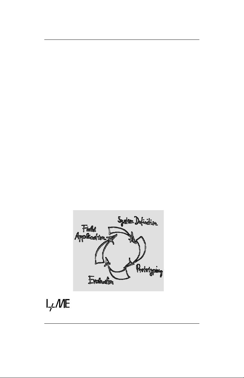
general industrial environments. Our products can be
used in all phases of system development: system
definition, prototyping, evaluation and field application.
Informatik und MikroElektronik
Page 4
Whether your professional background is into industryprocess-control or development and test tools, we offer
six product groups to fulfill your sophisticated needs.
Tried and tested under the most severe conditions the
automotive industry has to offer, our products have
proved themselves again and again.
Our six products groups are:
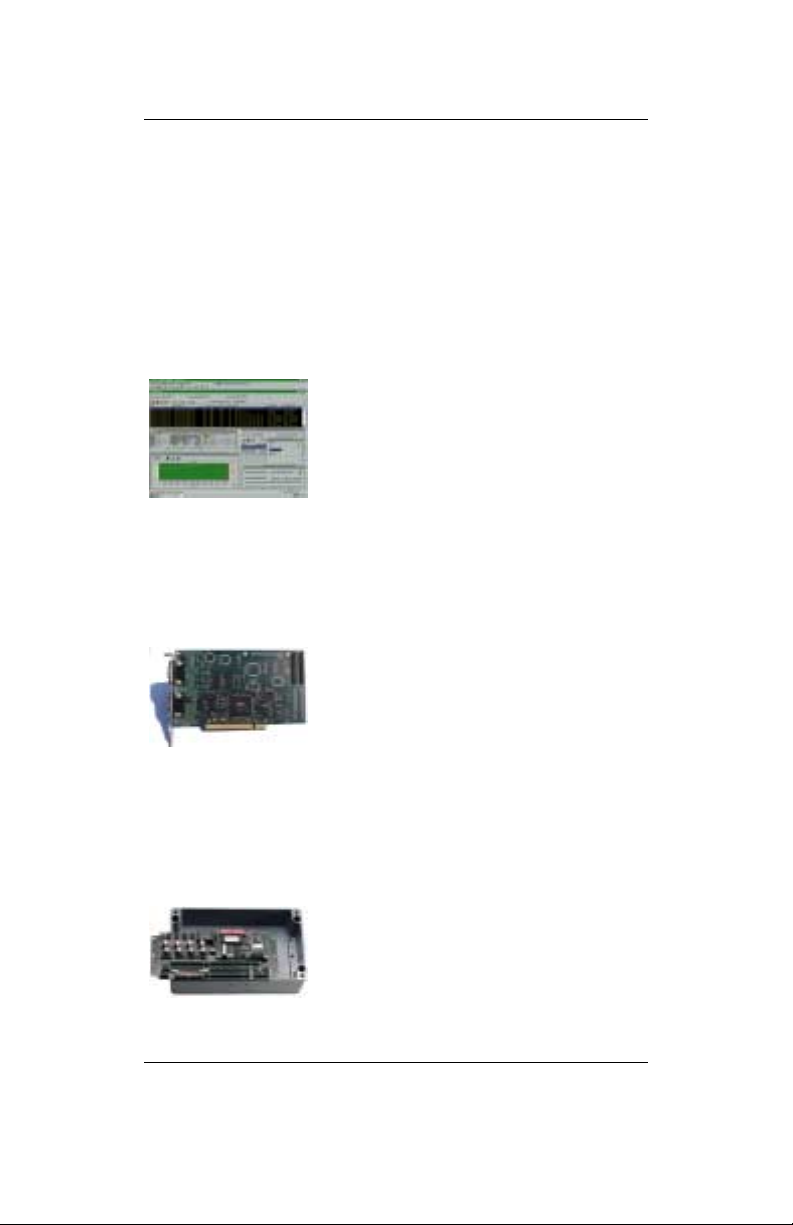
1 CAN System Test & Design Tools
Support of various user application phases: Learning, prototyping, testing and evaluation of
networked systems. Comfortable
Real-Time simulation of message
transfer characteristics in CAN
networks. Tools for mobile
diagnosis and tests.
2 CAN PC Interfaces
Easy interfacing betwe en PCs,
Laptops, notebooks and networks
with automotive fieldbus – protocols. Available for all PC standard
interfaces such as ISA-slot, PCI,
backplane, RS232, Centronics
and PCMCIA. Development of
applications under DOS/Windows according to RealTime requirements is supported
3 CAN Industrial I/O
NiPC is an intelligent hardware
concept for sensor / actuator inter-
facing. A modular architecture al-
lows the flexible change target
micro controllers for process
control.
Page 5
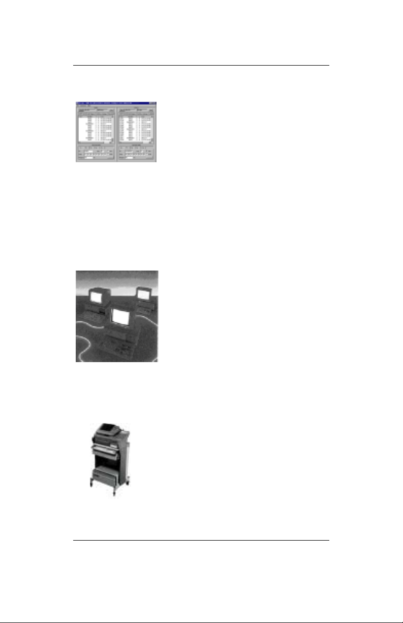
4 CAN System Application Software
Enabling Real-Time system
modeling, testing of networked
systems as well as application
support. Offering basic services
for network communication which
is applicable for various
processors and programming
languages. Facilitating the application interface for
distributed industrial process control according to the
CAL standard by CiA. Support of Windows 3.1,
Windows 95 & NT.
5 CAN System Know How
Promoting the understanding of
various network protocols in
practice. Understanding of CAN
networks with CAL in practice.
Developing HW/SW solutions for
customer specific problems. We
offer CAN / CAL workshops and
in-house seminars to enable CAN
users to benefit from I+ME
ACTIA’s extensive knowledge.
6 Automotive Diagnostics
Assistance during the development
phases. Diagnostic tools for quality
control in production lines as well as
after sales diagnostic, control and
servicing tools are provided to
manufacturers, suppliers and dealers
of the car industry by I+ME ACTIA.
If you have any questions concerning our products or
you look for specific solutions within our product groups,
Page 6

don’t hesitate to call us and benefit from I+ME’s
extensive knowledge - your need is our desire.
Our merger with the french corporation ACTIA in 1995
allowed us to become a powerful supplier for the
European automotive industry. ACTIA products include
diagnostic systems for automotive service and
maintenance as well as development and production of
high-quality on-board electronics. joining forces with
ACTIA has enabled I+ME to better service it’s
international customers not only in Europe, but
throughout the world.
Headquarter: Office Stuttgart:
I+ME ACTIA GmbH I+ME ACTIA GmbH
Rebenring 33 Zettachring 4, 1.OG
38106 Braunschweig 70567 Stuttgart
Germany Germany
T: +49 531 38701 0 T: +49 711 72874 45
F::+49 531 38701 88 F: +49 711 72874 46
WORLDWIDE REPRESENTATIVES
ACTIA INC.
SI-KWADRAAT
NOHAU UK LTD.
AiXIA SA
NOHAU ELEK. AB
ACTIA SA
I+ME
INDUSTRADE AG
DAIWA SANKO
Page 7

I+ME ACTIA Representatives
SI-KWADRAAT ACTIA SA
Nuenen, Netherlands Toulouse, France
T: +31 40 2631185 T: +33 05 61176161
F: +31 40 2838092 F: +33 05 61554231
NOHAU ELEK. AB ACTIA INC.
Malmö, Sweden Bedford, Texas USA
T: +46 40 592200 T: +1 817 5710435
F: +46 40 592229 F: +1 817 3559513
If needed, please contact our associates below.
ATAL SPOL SRO ACTIA DO BRASIL
Tabor, Czech Rep. Porte Alegre, Brazil
T: +420 361 251791 T: +55 51 9699802
F: +420 361 23043 F: +55 51 3411989
ATON SYSTEMS SA ACVIBUS SA
France Mexico
T: +33 01 42071800 T: +525 368 6169
F: +33 01 42078555 F: +525 368 5646
VIDEOBUS SA
Madrid, Spain
T: +34 1 5001950
F: +34 1 5000607
Page 8

Manual
NetPorty II
Contents
1 Introduction......................................... 1-1
1.1 Your I+ME NetPorty II ......................................1-2
1.2 System Requirements ......................................1-4
1.3 Delivery Contents .............................................1-5
1.3.1 Standard................................................1-5
1.3.2 Supplementary Support ........................1-5
1.4 Technical Specifications...................................1-6
2 Installation........................................... 2-1
2.1 Overview...........................................................2-2
2.2 Installing the Hardware.....................................2-2
2.3 Installing the Software ......................................2-4
2.3.1 If you start at serial port ........................2-4
2.3.2 If you start at parallel port .....................2-5
3 Hardware.............................................3-1
3.1 Micro controller.................................................3-2
3.2 Memory.............................................................3-3
3.2.1 NetPorty II internal buffers:...................3-3
3.3 Protocol Interface .............................................3-4
3.4 Physical Interface .............................................3-5
3.5 Optical interface................................................3-5
3.6 Connector.........................................................3-6
3.6.1 9pol sub-min-D male.............................3-6
3.6.1.1 1 CAN Channel..................................3-6
3.6.1.2 More than 1 CAN Channel ................3-8
3.6.2 25pol sub-min-D male.........................3-10
3.6.3 Cable set for serial connection............3-11
3.6.4 Power Supply......................................3-12
4 Troubleshooting & Techn. Support... 4-1
4.1 What to do if you have problems......................4-2
4.1.1 Solutions for all parts ... ........................4-3
4.1.2 Solutions for PCMCIA...........................4-4
1.1.1 Non-Supported PCMCIA Drives ...........4-5
4.1.3 Solutions for NetPorty II........................4-6
Page 9

5 Glossary.............................................. 5-1
6 Literature............................................. 6-1
A LevelX API
B LevelX Demos
C PcCANControl
Administration of Document
Document version: 1.05
Page 10

Page 11

Your I+ME NetPorty II. Overview,
Systemrequirements, Delivery contents and s.o.
1 Introduction
Page 12

Introduction
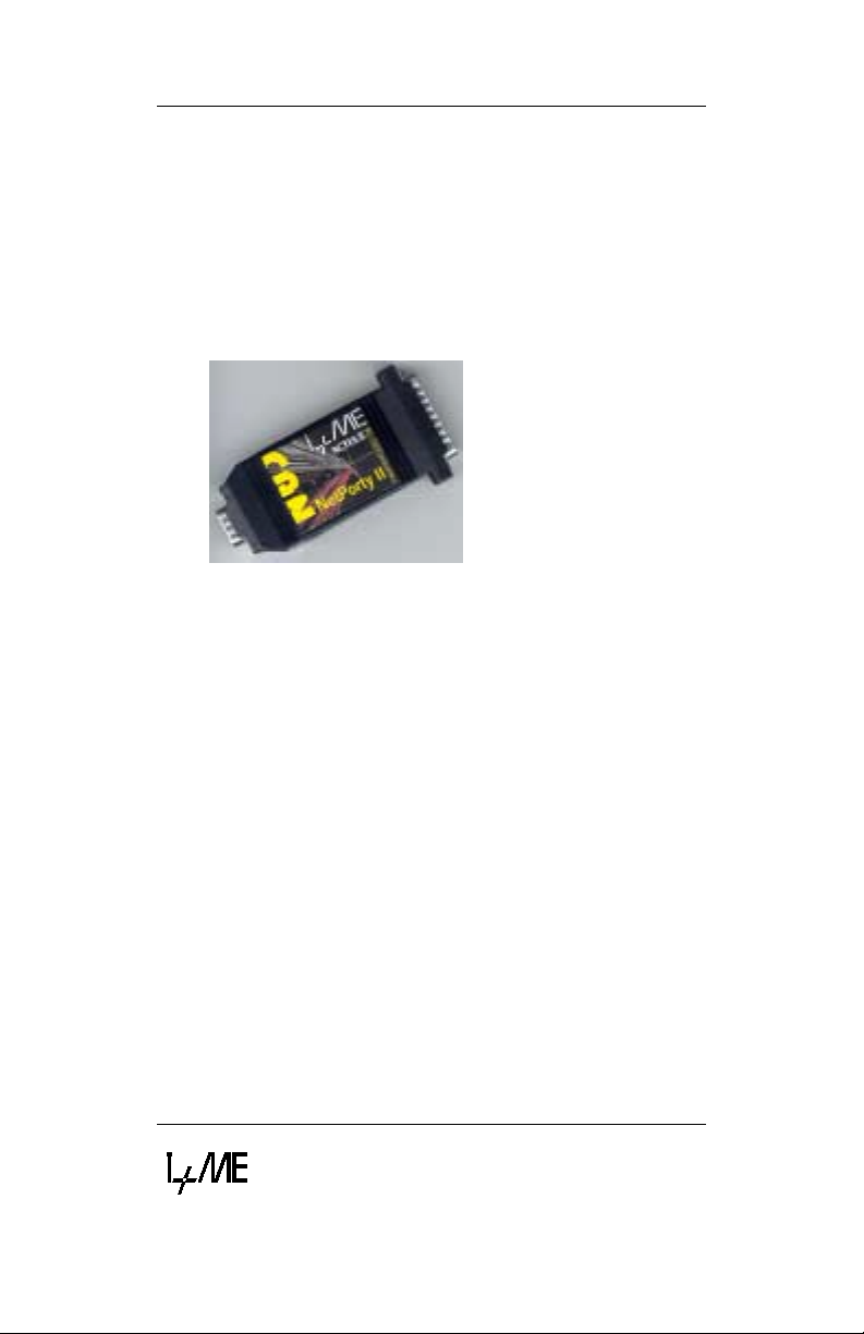
Your I+ME NetPorty II
1.1 Your I+ME NetPorty II
The NetPorty II is an improved portable network
adapter. It is designed to connect devices with RS232
or Centronics interfac e to t he C AN bus . With its features
it is an ideal general purpose har dware for industrial and
automotive analyzes and diagnostics.
With NetPorty II you can visualize bus-traffic and
configure components with in a CAN network. It en ables
you to transfer sof tware from or to control com ponents.
The data can be exporte d to readable by standard PC
programs like Excel. In t his way the user can generate
statistic diagrams, etc. to analyze the CAN
communication.
In the I+ME standard s oftware you can s et bus spec ific
values. For transmitted or rec eived data it is possible to
assign fix display to one CAN message.
In addition to the above mentioned features you can
transfer your own progr ams to NetPorty II b y the use of
the RS232 link. The download utilities are included as
well as sample programs.
The NetPorty II can optionally be equipped with an
UART for automotive diagnosis. In this case it is a
converter RS 232 or Centronics to ISO 9141 (K-Line).
Working with the parallel port is 2 ..5 times fas ter as the
serial port access. The speed depends on the PC
speed.
Version 1.03
1-2
Page 13

Your I+ME NetPorty II
Introduction
I+ME ACTIA is always eager to full fill the needs of our
customers. If problems should occur, please refer to
Troubleshooting. If the problem persists, then feel free
to contact our after-sales support hotline using the
following number:
After-sales service
* I+ME ACTIA GmbH
Rebenring 33
D-38106 Braunschweig
Germany.
Tel: ++ 49 (531) 38 701 38
Fax: ++ 49 (531) 38 701 88
e-mail : info@ime-actia.de
Version 1.03
1-3
Page 14

Introduction
System Requirements
1.2 System Requirements
PC requirements:
• standard PC with RS232 or Centronics (EPP 1.7 or
1.9) interface
• other device with standard RS232 interface (used
signals described in chapter Hardware)
Version 1.03
1-4
Page 15
Delivery Contents
1.3 Delivery Contents
1.3.1 Standard
Your NetPorty II delivery package
(Order code: IME 1602401) includes:
• 1 NetPorty II
• 1 System user manual (hardware/software)
• Transfer tools to NetPorty II
Introduction
• LevelX software driver for design of 32 bit Windows
applications (Windows '95 and Windows NT),
including sample programs running on standard
firmware
• PCCANControl for Windows, Windows '95 and
Windows NT version
• RS232 adapter cable set
1.3.2 Supplementary Support
• Power supply
• Different cables for protocol interfacing (on request)
Version 1.03
1-5
Page 16

Introduction
Technical Specifications
1.4 Technical Specifications
General Characteristics of NetPorty II
Processor 80C165, @36,84MHz
Protocol Interface 1 x SJA1000, @ 16 MHz
1 x 82527, @16MHz
1 x UART
Physical Interface CAN: according to ISO 11898
(PCA 82C251)
Memory 512 x 16 KByte RAM,
128 x 8 KByte Flash
Temperature Range 0° .. .+ 55 °C
Connector 9pin sub-min-D
CAN according to CiA/DS 102
Housing plastic, protection class IP30
Display 3 DUO-LED
Dimensions 95.5 mm x 41 mm x 20 mm
Power Supply 7 - 32 V DC external power
supply jack or via CAN bus
connector,
typically max.500 mA at 7 V
DC with physical interface
PCA 82C251
Version 1.03
1-6
Page 17

Technical Specifications
Introduction
Options
Memory 64 KB EPROM instead of flash
Physical interface: ISO Low Speed (ISO 11519)
Diagnosis Channel ISO 9141 physical interface
CAN CAN optional galvanic
disconnect
Cable 1 m Cable for adaptation
Power supply 230 V/AC to regulated 8 V/DC
110 V/AC to regulated 8 V/DC
Firmware Individual firmware on request
Version 1.03
1-7
Page 18

Page 19

Installing your NetPorty II. Step by step installation
procedures for hardware and software.
2 Installation
Page 20

Installation
Overview
2.1 Overview
This chapter gives detailed information about installing
the NetPorty II hardware and about the necessary
software drivers which make NetPorty II access
possible.
The NetPorty II is delivered with access driver and
applications for Windows 95 and Windows NT. To get
your NetPorty II operational follow the installation guide
lines.
2.2 Installing the Hardware
To install the hardware you should connect the
NetPorty II to the serial or to the parallel port of your PC.
If the NetPorty II operates at the serial port of the PC
the adapter cable will be used to get the right signals.
Plug in the 25 pin D-Sub connector of the adapter cable
to the NetPorty II and the 9 pin D-Sub connector to the
serial interface of the PC.
The NetPorty II can operate at the parallel port which
must be configured as EPP
2
ECP
.mode is not supported.
1
(V1.7 or V1.9) mode.
Make sure that the right interrupts are used in the
systems configuration and the BIOS settings.
1
EPP: Enhanced Parallel Port
2
ECP: Extended Capabilities Port
Version 1.03
2-2
Page 21

Installing the Hardware
pply
S23
Installation
It is also necessary to connect the NetPorty II with a
power supply. Therefore an external power unit can be
used to supply the NetPorty II via the power connector
or via the 9 Pin D-Sub CAN-connector.
CAN
Power
su
Serial
R
Centronics
2
If all connections are done NetPorty II is operational and
the next step is the software installation.
Version 1.03
2-3
Page 22

Installation
Installing the Software
2.3 Installing the Software
2.3.1 If you start at serial port
Driver installation:
1 Insert the CD. The setup programm will start
automatic, if not please start the program
“START.EXE” in root path.
2 Go to "Software Installation"
3 Choose your operating system, is important.
4 Choose your hardware component at the selection
box then press "Start Installation". If the file is started
(*.com file), follow the steps on the screen. If
necessay type in the password.
5 If password is correct software will be installed
successful.
Application installation:
1 Insert the CD. The setup programm will start
automatic, if not please start the program
“START.EXE” in root path.
2 Go to "Software Installation"
3 Choose your operating system, is important.
4 Choose PcCANControl component at the selection
box then press "Star t Ins ta lla ti on ". If the file is s tarted
(*.com file), follow the steps on the screen. If
necessay type in the password.
5 Start PcCANControl, select “create a new project”
and the NetPorty II hardware, at this case “Porty2COM1” or “Porty2-COM2”. After the selection the
necessary NetPorty II software is activated on your
PC. For further information see also chapter about
PcCANControl.
It is not necessary to install a driv er. The software works
with the standard Win32 serial communication services
with 115200bps, 8 bits, no parity, 1 stop bit.
Version 1.03
2-4
Page 23

Installing the Software
Installation
Problems:
It is possible you chose an incorrect COM port. Start
PcCANControl again and choose an other COM port.
2.3.2 If you start at parallel port
1 Make sure that your PC parallel por t uses the EPP-
mode. You have to control it under BIOS setup. In
this version the NetPorty II supported the EPP
versions 1.7 and 1. 9. If neces sary conf igure your PC
and re-start it.
2 Follow steps 1-5 under chapter 2.3.1.
3 Configure the right driver. Change to directory
“.. / I+ME ACTIA / CANctrl-PTY / ParDrv95
(.. / ParDrvNT) and start the batch-file Drvinst.bat
4 At this point you ha ve to reboot your PC to start t he
right driver.
5 Install PcC ANContro l, follow steps 1-5 under chapter
2.3.1 Application installation.
Problems: (see also chapter troubleshootings)
You start PcCANControl but the connection doesn’t
work:
For parallel port usage it is necessary to have the EPPloader-firmware (BOOTLOAD.H86) in the NetPorty II Flash-EPROM.
All Porty's are delivered with this loader but it is possible
that you have overwritten it by your own firmware.
In this case it is possible to download the EPP-firmware
again into the NetPorty II -Flash.
Version 1.03
2-5
Page 24

Installation
Installing the Software
This software is a Win32-Console-Application and runs
under Win95 and WinNT.
Usage:
- Connect your NetPorty II with one serial port.
- If you do not use COM1 please change it into the file
L.BAT.
-Start L.BAT.
- If you get error messages like
"BSL: no response from the target hardware"
it is possible that you have used the wrong COM
port.
- If you get the message below
"-- COMx Loading bootload.h86..Ready"
without any error message in the next line, all
activities are correct finished
- Leave the software with pressing the ESC key,
sometimes Alt X does not work.
Info:
The program LDFSER.EXE is a loader that burns
firmware in the Porty-Flash and also it is a serial monitor
to display firmware print-outs.
The serial parameter are 115200,8,n,1.
I+ME also can deliver a loader to start firmware in the
RAM and a little firmware demo (Keil-C).
Please contact us if you want to develop your own
firmware.
Version 1.03
2-6
Page 25

The technical components, there specifications and the
way they work together.
3 Hardware
Page 26

Hardware
Micro controller
3.1 Micro controller
The I+ME NetPorty II includes the 16-bit Siemens
80C165 micro controller on a piggy back. The
controller’s clock frequency is 36,84MHz.
The following recourses are used:
Port 2.14 [EX6IN] SJA1000
Port 2.15 [EX7IN] 82527 / 16CS550
CS0-CS1 Memory
CS2-CS3 Protocol interface
CS4 LED latch
Version 1.03
3-2
Page 27

Hardware
Memory
3.2 Memory
The I+ME NetPorty II is equipped with
Flash (CS0) 128 KByte (x 8 bit)
SRAM (CS1) 512 KByte (x 16 bit)
Optional it can be equipped with
Flash 512 KByte (x 8 bit) and
RAM 128 Kbyte (x 16 bit)
3.2.1 NetPorty II internal buffers:
To avoid lost data (CAN is faster than the
communication chan nels to the PC) the transfer- objects
are buffered in the NetPorty II. The biggest buffer is
between CAN reception and the communication
channel to the PC (448k Byte). If you have man y traffic
on the CAN-bus and the buff er is full it takes a time of
several minutes to transfer the data to t he PC. You can
control this with the 2nd NetPorty II LED that blinks
faster while the data transfer.
Version 1.03
3-3
Page 28

Hardware
Protocol Interface
3.3 Protocol Interface
The product has two CAN protocol chips at a frequency
of 16 MHz. The SJA1000 chip is connected to the 9 pin
D-SUB connector with the CiA pinning. The optional
82527 is also connected to the 9 pin D-Sub connector
without physical line driver .
The C165 uses the CS2 signal to select the SJA1000.
The NetPorty II can be equipped with a second CAN
channel. Therefore a 82527 will be mounted on the
PCB. The C165 uses the CS3 signal to select the
82527.
If 2 CAN channels are used there is no standard pinning
at the D-Sub connector. The physical line driver for the
second CAN channel is available via the connecting
cable (not included in standard delivery contents) and
can be used optional by your special app lic a tion.
In stade of the second CAN channel a diagnosis
channel can be used. Therefor an UART 16CS550 can
be mounted on the PCB instead of the 82527. The
C165 uses the CS3 signal to select the UART.
The physical line driver for the ISO 9141 interfacing can
be ordered separately
Version 1.03
3-4
Page 29

Hardware
Physical Interface
3.4 Physical Interface
NetPorty II has the transceiver chip 82C251 (according
to ISO 11898) as physical interf ac e. It is not galvanic
disconnect. The standard physical interface is linked to
the SJA1000, the Output Control Register must be set
to 0xFA.
To connect the second CAN channel or the ISO 9141
channel an optional physical line driver have to be
ordered.
3.5 Optical interface
State of LED during download firmware:
At serial download: no fixed state.
At parallel download LED 1 green
LED 2 green (flashing)
State of LED during work:
Color LED 1 LED 2 LED 3
Red - - Bus off
green Life cycle flash Flashing during
RS232/Parallel
data transfer
2. Data transfer 3. BUS on/off1.Life cycle flash
Bus on
Version 1.03
3-5
Page 30

Hardware
Connector
3.6 Connector
3.6.1 9pol sub-min-D male
3.6.1.1 1 CAN Channel
The CAN connector is based on the CiA standard if only
one CAN channel is used. It is a 9pol sub-min-D male
connector.
Figure 3-1 Standard CAN Connector
Pins 1, 4 and 8 are not used by NetPorty II
Version 1.03
3-6
Page 31

Hardware
Connector
Pin Signal Description
1 nc not connected
2 CAN_L CAN_L bus line (dominant low)
3 CAN_GND CAN ground
(connected on the cable shield)
4 nc not connected
5 CAN_SHIELD CAN ground
(connected on the cable shield)
6 POWER_GND power supply input ground
7 CAN_H CAN_H bus line (dominant
high)
8 nc not connected
9 POWER_V+ power supply input +7..32V
The power input and the CAN lines are galvanic
disconnect with a limit to ± 50V. There is an internal
transzorb diode to limit the disconnect voltage.
If you don't need a galvanic disconnect, the pin 6 can be
connected to pin 3 or 5.
The POWER_GND pin 6 is not connected with the CiA
standard bus in every system. If the tool does not work,
pin 6 could have to get connected to the power supply
ground!
Version 1.03
3-7
Page 32

Hardware
Connector
3.6.1.2 More than 1 CAN Channel
The pinning is different if more than one CAN channel is
used.
Figure 3-2 Pinning for more than 1 CAN channel
Version 1.03
3-8
Page 33

Hardware
Connector
Pin Signal Description
1 Uni_Out2 Connected to Port 6.7
2 CAN_L CAN_L bus line (dominant low)
3 CAN_GND CAN ground
(connected on the cable shield)
4 Uni_Out0 Connected to Port 6.5 or UART
Rx or CAN2 RX
0
5 CAN_SHIELD CAN ground
(connected on the cable shield)
6 POWER_GND power supply input ground
7 CAN_H CAN_H bus line (dominant
high)
8 Uni_Out1 Connected to Port 6.6 or UART
Tx or CAN2 TX
0
9 POWER_V+ power supply input +7..32V
Pin 1, 4 and 8 are used to provide the additional signals
for the second CAN channel or the UART. In standard
version the inputs are protected.
Port 6.5, Port 6.6 and Port 6.7 are used as additional
signal line. In case of standard version the ports are
protected.
Version 1.03
3-9
Page 34

Hardware
Connector
3.6.2 25pol sub-min-D male
To connect the NetPorty II with the PC it is possible to use the
Centronics (LPT) port directly or to use the adapter cable to
use the RS232 (COM) port. In both cases the pinning of the
25pol sub-min-D male is the same.
Connector definition:
Pin I/O Usage Description
1 Input Parallel Strobe
2 Input Parallel D0
3 Input Parallel D1
4 Input Parallel D2
5 Input Parallel D3
6 Input Parallel D4
7 Input Parallel D5
8 Input Parallel D6
9 Input Parallel D7
10 Output Parallel /acknlg
11 Output Parallel Busy
12 Output Parallel Paper em pty
13 Output Parallel Slct
14 Input Parallel /autofd
15 Output Parallel /error
16 Input Both
17 Input Parallel / slct in
18 X Both Ground
19 Input Serial TX (PC -> Porty)
20 Output Serial RX (Porty -> PC)
21 Input Serial RTS
22 Output Serial CTS
23 Input Serial Free input (DTR)
24 Output Serial DSR
25 Input Serial Free input (as serial master it can be used as
high -> RESET; low -> Operational
/init DTR (Porty RESET in): switch level 2.5V
input range -40..+40V, low speed 10ms
A weak pull-up and pull-down is necessary to
define with special mounting whether the
reset line is active or not if this line is not
connected.
CD or RI)
and also optional power input source
Version 1.03
3-10
Page 35

3.6.3 Cable set for serial connection
Cable length: 30cm
25 pin female 9 pin female Signal
23 1 CD
20 2 Rx
19 3 Tx
16 4 DTR
18 5 GND
24 6 DSR
21 7 RTS
22 8 CTS
25 9 RI
Hardware
Connector
Version 1.03
3-11
Page 36
Hardware
Connector
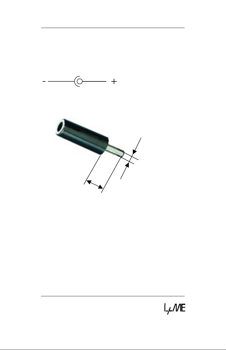
3.6.4 Power Supply
The NetPorty II can be powered by an external power
supply Therefore the connector is specified for the
power supply jack below:
The power connector is a DC3.5/1.3 mm type. That
means the internal diameter is 1.3mm.
Ø3,5mm
min. 9,0mm
Figure 3-3 Power Connector for NetPorty II
Version 1.03
3-12
Page 37

Common problems and how to solve them. How to get
in touch with our after-sales support experts if you so
desire.
4 Troubleshooting &
Techn. Support
Page 38

Troubleshooting &
Techn. Support
What to do if you have problems
4.1 What to do if you have problems
First and foremost, please read Installation very closely
and make sure that you performed your installation
exactly as described.
For developers:
The Key is often used in developing en vir onments in
combination with the API and/or DLL. If the
PcCANControl software is functioning properly, then
there is no problem with general CAN access. You
should check your usage of the API of DLL.
If the PcCANControl software is not functioning, please
consult the list of common problems below and their
possible solutions.
Version 1.03
4-2
Page 39

Troubleshooting &
What to do if you have problems
Techn. Support
4.1.1 Solutions for all parts ...
The system crashes after choose the hardware at
PcCANControl:
The selected memory area is not free, or the
selected interrupt is being used by another
application. Make sure that no conflicts exist on
your system. If you get a blue screen under Win
NT it is most likely that a memory or IRQ conflict
is occur.
PcCANControl launches correctly, but CAN access
is not possible:
Check the transceiver cable and CAN
connectors. If a connector is not correctly
plugged, connect it right. If the sub-min-D
connectors at the end of the cables are hot,
remove the Key and call I+ME.
If you use higher baudrates, remember to
protect the end of line with resistors [120Ohm]
Version 1.03
4-3
Page 40

Troubleshooting &
Techn. Support
What to do if you have problems
4.1.2 Solutions for PCMCIA
The system crashes after the installation of the Key
client:
The selected memory area is not free, or the
selected interrupt is being used by another
application. Refer to Installation.
The system crashes when the Key is inserted or
removed:
The selected memory area is not free, or the
selected interrupt is being used by another
application. Refer to Installation.
Windows will not launch after the installation of the
client and services:
Make sure that there is a memory area reserved
in the SYSTEM.INI file. The selected memory
area is not free, or the selected interrupt is being
used by another application. Refer to Installation.
The acknowledge sound after inserting or removing
the Key is sounded twice:
There are two se rvices installed on your system.
One can be found in the CONFIG.SYS and the
other in the device manager. In the device
manager, under the topic PCMCIA, you can
disable one of the services.
The Key is not inserted and PcCANControl starts
with the message: I+ME CARD not available or drive
not ready.
Insert the Key.
Version 1.03
4-4
Page 41

Troubleshooting &
What to do if you have problems
Techn. Support
The Key is inserted and PcCANControl starts with
the message: I+ME CARD not available or drive not
ready.
Some aspect of the resource allocation is wrong.
Refer to Installation for more information.
1.1.1 Non-Supported PCMCIA Drives
In the current version there are some PCMCIA drives
which are incompatible with the PCMCIA Key. Today,
as a general rule, some PCI connected drives result in
compatibility problems. The following is a list of known
incompatible drives and any laptops which are known to
use these drives.
Drive Known Laptops Using Drive
Cirrus Logic
PCIC compatible
SIEMENS NIXDORF Scenic Mobile 700
COMPAQ Armada
Version 1.03
4-5
Page 42

Troubleshooting &
Techn. Support
What to do if you have problems
4.1.3 Solutions for NetPorty II
You start PcCANControl but the connection doesn’t
work correct:
For parallel port usage it is necessary to have the
EPP-loader-firmwar e (BOO TLO AD.H86) in the
NetPorty II -Flash-EPROM. All Porty's are
delivered with this loader!
You have overwrite the delivered EPP-Loader by
your own firmware.
In this case it is possible to download the EPPfirmware again into the NetPorty II -Flash. This
software is a Win32-Console-Application and
runs under Win95 and WinNT.
How to use:
- Connect your NetPorty II with one serial port.
- If you do not use COM1 please change it into
the file L.BAT.
-Start L.BAT.
If you get an error messages like
"BSL: no response from the target hardware"
it is possible that you have used the wrong
COM port.
- If you get the message below
"-- COMx Loading bootload.h86..Ready"
without any error message in the next line, all
activities are correct finished
- Leave the software with pressing the ESC key,
sometimes Alt X does not work.
Info:
The program LDFSER.EXE is a loader that burns
firmware in the Porty-Flash and also it is a serial monitor
The serial parameter are 115200,8,n,1. I+ME also can
deliver a loader to start firmware in the RAM and a little
firmware demo (Keil-C). Please contact us if you want to
develop your own firmware.
Version 1.03
4-6
Page 43

Troubleshooting &
What to do if you have problems
Techn. Support
The NetPorty II doesn’t work under parallel port:
Use the right EPP mode on BIOS. It can be only
one of the EPP modes work with one Win-System
together. In past we find out that EPP 1.7 is
necessary for Win9x and EPP 1.9 is necessary
for Win NT. Please try out the right mode.
Using a printer and NetPorty II under Win NT:
If you use NetPorty II under NT note that you are
not able to print!
Using a printer and NetPorty II under Win 9x:
If you use NetPorty II under Win9x the normal
printer driver is active but it can make prob le ms
while printing with the active driver.! One way to
solve this problem is to load the firmware into the
flash of the NetPorty II.
Version 1.03
4-7
Page 44

Troubleshooting &
Techn. Support
What to do if you have problems
If you encounter difficulties which are not discussed in
the manual, or if you need more help than is offered in
Installation and Troubleshooting, please call our
after-sales service. Our experts will do their best to
solve whatever problem you might have.
Version 1.03
4-8
Page 45

For better understanding...
5 Glossary
Page 46

Glossary
Glossary
Adapter
A piece of hardware which
contains one or more PCMCIA
sockets.The Adapter contains
the interface between the
Socket Controller and the Host
System.
AUTOEXEC.BAT
A set of commands in the form
of a batch file program that are
automatically executed by DOS
to help configure your system
when you Boot-Up your
computer.
BIOS
An abbreviation for Basic
Input/Output System. A set of
instructions/routines stored in
ROM. These routines work
closely with hardware devices
(memory chips, disk drives and
monitor) to input and output
interrupt requests indicating
when a device is ready to
accept or send data.
CONFIG.SYS
A system configuration command file that contains installable device drivers, memory
management commands and
control files that DOS accesses
and uses when your system
starts up.
I/O
An abbreviation for lnput
Output. Refers to the sending
(input) and receiving (output) of
data through an 110 channel in
the CPU. Example: The
keyboard inputs data to the 110
channel in the CPU that in turn
is output to the monitor.
IRQ
An abbreviation for Interrupt
Request. A signal sent by a
device and routed through the
BIOS indicating when a device
is ready to accept or send data.
PCMCIA
Personal Computer Memory
Card International Association,
a trade association of leading
hardware and software
vendors, established to adopt a
set of standards pertaining to
adapter slots and PC cards for
portable PC accessories.
Slot
A receptacle on a micro,
portable, laptop or palmtop
computer that is used to insert
and operate PCMCIA PC
Cards. Also referred to as a
Socket.
Socket
Same as Slot (see above).
DPRAM
Dual Ported Random Access
Memory. The data for
communication between PC
and CANcard are exchange via
a DPRAM.
5-2
Page 47

Socket-Controller
A PC system hardware
component that manages the
operation of PCMCIA sockets in
conjunction with system
software.
SYSTEM.INI
A Windows initialization file
(similar to the CONFIG.SYS file
for DOS) that contains Windows
device drivers, commands and
settings you can use to
customize Windows for your
system's hardware.
Upper-Memory
Memory area within the PC
address space between 640 KB
and 1 MB. This area is used by
hardware devices like graphics
controller. The DPRAM of the
CANcard is located in the
Upper Memory.
Glossary
V 1.00
5-3
Page 48

Page 49

For more informations ...
6 Literature
Page 50

Literature
Literature
[1] SAB 80C167CR User Manual
Siemens AG.
[2] SAB C167CR Description of the
On-chip CAN-Module
Siemens AG.
[3] CiA DS 102-1CAN in Automation e.V
6-2
 Loading...