

Page 1

HSZ80 Array Controller ACS Version 8.3
Configuration and CLI Reference Guide
First Edition (December 1998)
Part Number EK-HSZ80-RG. A01/388222-001
Compaq Computer Corporation
Page 2

While Compaq Computer Corpo ration belie v es the informat ion included in this manual i s correct as of th e date
of publication, it is subject to change without notice. Compaq makes no representations that the interconnection of its products in the manner described in this document will not infringe existing or future patent rights,
nor do the descriptions contained in this document imply the granting of licenses to make, use, or sell equipment or software in accordance with the description. No respon sibi lity is assumed for the use or reliabili ty of
firmware on equipment not supplied by Compaq or its affiliated companies. Possession, use, or copying of the
software or firmware described in this documentation is authorized only pursuant to a valid written license
from Compaq, an authorized sublicensor, or the identified licensor.
Commercial Computer Software, Computer Software Documentation and Technical Data for Commercial
Items are licensed to the U.S. Government with Compaq’s standard commercial license and, when applicable,
the rights in DFAR 252.22 7 70 15 , "Tec hn ic al Da ta -C omm erc ia l I te ms."
© 1998 Compaq Computer Corporation.
All rights reserved. Printed in U.S.A.
Compaq, the Compaq logo, DIGITAL, DIGITAL UNIX, DECconnect, HSZ, HSG, StorageWorks, VMS,
OpenVMS Registered in the United States Patent and Trademark Office.
UNIX is a registered trademark in the United States and other countries exclusively through X/Open Company
Ltd. Windows NT is a registered trademark of the Microsoft Corporation. Sun is a registered trademark of Sun
Microsystems, Inc. Hewlett-Packard, TACHYON, and HP-UX are registered trademarks of the Hewlett-Packard Company. IBM and AIX are registered trademarks of International Business Machines Corporation. All
other trademarks and registered trademarks are the property of their respective owners.
This equipment has been tested and found to comply with the limits for a Class A digital device, pursuant to
Part 15 of the FCC Rules. These limits are designed to provide reasonable protection against harmful interference when the equipment is operated in a commercial environment. This equipment generates, uses and can
radiate radio frequency energy and, if not installed and used in accordance with the manuals, may cause harmful interference to radio communications. Operation of this equipment in a residential area is likely to cause
harmful interference in which case the user will be required to correct the interference at his own expense.
Restrictions apply to the use of the local-connection port on this series of controllers; failure to observe these
restrictions may result in harmful interference. Always disconnect this port as soon as possible after completing the setup operation. Any changes or modifications made to this equipment may void the user's authority to
operate the equipment.
Warning!
This is a Class A product. In a domestic environment this product may cause radio interference in which case
the user may be required to take adequate measures.
Achtung!
Dieses ist ein Gerät der Funkstörgrenzwertklasse A. In Wohnbereichen können bei Betrieb dieses Gerätes
Rundfunkstörungen auftreten, in welchen Fällen der Benutzer für entsprechende Gegenmaßnahmen verantwortlich ist.
Attention!
Ceci est un produit de Classe A. Dans un environnement domestique, ce produit risque de créer des interférences radioélectriques, il appartiendra alors à l'utilisateur de prendre les mesures spécifiques appropriées.
Page 3
JAPAN
USA
This equipment gener ates, uses, an d may emit r adio fr equenc y en er gy. The equip ment ha s been ty pe test ed and
found to comply with the limits for a Class A digital device pursuant to Part 15 of FCC rules, which are
designed to provide reasonable protection against such radio frequency interference. Operation of this equi pment in a residential area may cause interference in which case the user at his own expense will be required to
take whatever measures may be requir e d to correct the interference. Any modifications to this device - unless
expressly approved by the manufacturer - can void the user’ s authority to operate this equipment under part 15
of the FCC rules.
Page 4

Page 5

About This Guide
Getting Help. . . . . . . . . . . . . . . . . . . . . . . . . . . . . . . . . . . . . . . . . . . . . . . . . . . . . . . . xv
Precautions. . . . . . . . . . . . . . . . . . . . . . . . . . . . . . . . . . . . . . . . . . . . . . . . . . . . . . . . xvi
Conventions . . . . . . . . . . . . . . . . . . . . . . . . . . . . . . . . . . . . . . . . . . . . . . . . . . . . . . xviii
Required Tools. . . . . . . . . . . . . . . . . . . . . . . . . . . . . . . . . . . . . . . . . . . . . . . . . . . . . . xx
Related Publications . . . . . . . . . . . . . . . . . . . . . . . . . . . . . . . . . . . . . . . . . . . . . . . . xxi
Revision History . . . . . . . . . . . . . . . . . . . . . . . . . . . . . . . . . . . . . . . . . . . . . . . . . . xxii
Chapter 1
General Description
Typical Installation . . . . . . . . . . . . . . . . . . . . . . . . . . . . . . . . . . . . . . . . . . . . . . . . . 1–2
Summary of HSZ80 Features . . . . . . . . . . . . . . . . . . . . . . . . . . . . . . . . . . . . . . . . . 1–5
The HSZ80 Array Controller. . . . . . . . . . . . . . . . . . . . . . . . . . . . . . . . . . . . . . . . . . 1–7
Cache Module . . . . . . . . . . . . . . . . . . . . . . . . . . . . . . . . . . . . . . . . . . . . . . . . . . . . 1–18
External Cache Battery . . . . . . . . . . . . . . . . . . . . . . . . . . . . . . . . . . . . . . . . . . . . . 1–29
Chapter 2
Configuring an HSZ80 Array Controller
Introduction . . . . . . . . . . . . . . . . . . . . . . . . . . . . . . . . . . . . . . . . . . . . . . . . . . . . . . . 2–2
Configuring an HSZ80 Array Controller. . . . . . . . . . . . . . . . . . . . . . . . . . . . . . . . . 2–3
Setting the PVA Module ID Switch . . . . . . . . . . . . . . . . . . . . . . . . . . . . . . . . . . . . 2–25
Establishing a Local Connection to the Controller . . . . . . . . . . . . . . . . . . . . . . . . 2–26
Selecting a Failover Mode. . . . . . . . . . . . . . . . . . . . . . . . . . . . . . . . . . . . . . . . . . . 2–29
Enabling Mirrored Write-Back Cache. . . . . . . . . . . . . . . . . . . . . . . . . . . . . . . . . . 2–31
Setting SCSI Target ID Numbers. . . . . . . . . . . . . . . . . . . . . . . . . . . . . . . . . . . . . . 2–33
Using Preferred ID Numbers. . . . . . . . . . . . . . . . . . . . . . . . . . . . . . . . . . . . . . . . . 2–35
v
Compaq HSZ80 Array Controller ACS Version 8.3 Configuration and CLI Reference Guide
Page 6

vi
Chapter 3
Creating Storagesets
Introduction . . . . . . . . . . . . . . . . . . . . . . . . . . . . . . . . . . . . . . . . . . . . . . . . . . . . . . . 3–2
Planning and Configuring Storagesets. . . . . . . . . . . . . . . . . . . . . . . . . . . . . . . . . . . 3–4
Creating a Storageset and Device Profile . . . . . . . . . . . . . . . . . . . . . . . . . . . . . . . . 3–5
Determining Storage Requirements. . . . . . . . . . . . . . . . . . . . . . . . . . . . . . . . . . . . . 3–7
Choosing a Storageset Type. . . . . . . . . . . . . . . . . . . . . . . . . . . . . . . . . . . . . . . . . . . 3–8
Cloning Data for Backup. . . . . . . . . . . . . . . . . . . . . . . . . . . . . . . . . . . . . . . . . . . . 3–20
Backing Up Your Subsystem Configuration . . . . . . . . . . . . . . . . . . . . . . . . . . . . . 3–25
Node IDs . . . . . . . . . . . . . . . . . . . . . . . . . . . . . . . . . . . . . . . . . . . . . . . . . . . . . . . . 3–30
Assigning Unit Numbers for Host Access to Storagesets . . . . . . . . . . . . . . . . . . . 3–32
Creating a Storageset Map. . . . . . . . . . . . . . . . . . . . . . . . . . . . . . . . . . . . . . . . . . . 3–34
Planning Partitions. . . . . . . . . . . . . . . . . . . . . . . . . . . . . . . . . . . . . . . . . . . . . . . . . 3–40
Choosing Switches for Storagesets and Devices . . . . . . . . . . . . . . . . . . . . . . . . . . 3–42
RAIDset Switches . . . . . . . . . . . . . . . . . . . . . . . . . . . . . . . . . . . . . . . . . . . . . . . . . 3–43
Mirrorset Switches. . . . . . . . . . . . . . . . . . . . . . . . . . . . . . . . . . . . . . . . . . . . . . . . . 3–45
Device Switches. . . . . . . . . . . . . . . . . . . . . . . . . . . . . . . . . . . . . . . . . . . . . . . . . . . 3–48
Initialize Switches . . . . . . . . . . . . . . . . . . . . . . . . . . . . . . . . . . . . . . . . . . . . . . . . . 3–51
Unit Switches. . . . . . . . . . . . . . . . . . . . . . . . . . . . . . . . . . . . . . . . . . . . . . . . . . . . . 3–58
Chapter 4
Configuring Storagesets
Introduction . . . . . . . . . . . . . . . . . . . . . . . . . . . . . . . . . . . . . . . . . . . . . . . . . . . . . . . 4–2
Configuring with the Command Console LUN. . . . . . . . . . . . . . . . . . . . . . . . . . . 4–19
Configuring Units with Multiple Hosts. . . . . . . . . . . . . . . . . . . . . . . . . . . . . . . . . 4–23
Moving Storagesets . . . . . . . . . . . . . . . . . . . . . . . . . . . . . . . . . . . . . . . . . . . . . . . . 4–35
Page 7

Chapter 5
CLI Commands
CLI Overview . . . . . . . . . . . . . . . . . . . . . . . . . . . . . . . . . . . . . . . . . . . . . . . . . . . . . 5–2
ADD DISK . . . . . . . . . . . . . . . . . . . . . . . . . . . . . . . . . . . . . . . . . . . . . . . . . . . . . . . 5–7
ADD MIRRORSET. . . . . . . . . . . . . . . . . . . . . . . . . . . . . . . . . . . . . . . . . . . . . . . . 5–11
ADD PASSTHROUGH. . . . . . . . . . . . . . . . . . . . . . . . . . . . . . . . . . . . . . . . . . . . . 5–16
ADD RAIDSET. . . . . . . . . . . . . . . . . . . . . . . . . . . . . . . . . . . . . . . . . . . . . . . . . . . 5–19
ADD SPARESET . . . . . . . . . . . . . . . . . . . . . . . . . . . . . . . . . . . . . . . . . . . . . . . . . 5–23
ADD STRIPESET. . . . . . . . . . . . . . . . . . . . . . . . . . . . . . . . . . . . . . . . . . . . . . . . . 5–24
ADD UNIT . . . . . . . . . . . . . . . . . . . . . . . . . . . . . . . . . . . . . . . . . . . . . . . . . . . . . . 5–27
CLEAR_ERRORS CLI . . . . . . . . . . . . . . . . . . . . . . . . . . . . . . . . . . . . . . . . . . . . . 5–35
CLEAR_ERRORS controller INVALID_CACHE. . . . . . . . . . . . . . . . . . . . . . . . 5–36
CLEAR_ERRORS device-name UNKNOWN . . . . . . . . . . . . . . . . . . . . . . . . . . . 5–38
CLEAR_ERRORS unit-number LOST_DATA. . . . . . . . . . . . . . . . . . . . . . . . . . . 5–40
CLEAR_ERRORS unit-number UNWRITEABLE_DATA . . . . . . . . . . . . . . . . . 5–42
CONFIGURATION RESET . . . . . . . . . . . . . . . . . . . . . . . . . . . . . . . . . . . . . . . . . 5–44
CONFIGURATION RESTORE . . . . . . . . . . . . . . . . . . . . . . . . . . . . . . . . . . . . . . 5–45
CONFIGURATION SAVE . . . . . . . . . . . . . . . . . . . . . . . . . . . . . . . . . . . . . . . . . . 5–47
CREATE_PARTITION . . . . . . . . . . . . . . . . . . . . . . . . . . . . . . . . . . . . . . . . . . . . . 5–48
DELETE container-name . . . . . . . . . . . . . . . . . . . . . . . . . . . . . . . . . . . . . . . . . . . 5–51
DELETE FAILEDSET . . . . . . . . . . . . . . . . . . . . . . . . . . . . . . . . . . . . . . . . . . . . . 5–53
DELETE SPARESET . . . . . . . . . . . . . . . . . . . . . . . . . . . . . . . . . . . . . . . . . . . . . . 5–54
DELETE unit-number . . . . . . . . . . . . . . . . . . . . . . . . . . . . . . . . . . . . . . . . . . . . . 5–55
DESTROY_PARTITION. . . . . . . . . . . . . . . . . . . . . . . . . . . . . . . . . . . . . . . . . . . . 5–57
DIRECTORY. . . . . . . . . . . . . . . . . . . . . . . . . . . . . . . . . . . . . . . . . . . . . . . . . . . . . 5–59
HELP . . . . . . . . . . . . . . . . . . . . . . . . . . . . . . . . . . . . . . . . . . . . . . . . . . . . . . . . . . . 5–60
INITIALIZE . . . . . . . . . . . . . . . . . . . . . . . . . . . . . . . . . . . . . . . . . . . . . . . . . . . . . 5–62
LOCATE . . . . . . . . . . . . . . . . . . . . . . . . . . . . . . . . . . . . . . . . . . . . . . . . . . . . . . . . 5–67
vii
Compaq HSZ80 Array Controller ACS Version 8.3 Configuration and CLI Reference Guide
Page 8

viii
MIRROR . . . . . . . . . . . . . . . . . . . . . . . . . . . . . . . . . . . . . . . . . . . . . . . . . . . . . . . . 5–70
POWEROFF . . . . . . . . . . . . . . . . . . . . . . . . . . . . . . . . . . . . . . . . . . . . . . . . . . . . . 5–74
REDUCE . . . . . . . . . . . . . . . . . . . . . . . . . . . . . . . . . . . . . . . . . . . . . . . . . . . . . . . . 5–77
RENAME. . . . . . . . . . . . . . . . . . . . . . . . . . . . . . . . . . . . . . . . . . . . . . . . . . . . . . . . 5–81
RESTART controller . . . . . . . . . . . . . . . . . . . . . . . . . . . . . . . . . . . . . . . . . . . . . . 5–83
RETRY_ERRORS unit-number UNWRITEABLE_DATA . . . . . . . . . . . . . . . . . 5–85
RUN. . . . . . . . . . . . . . . . . . . . . . . . . . . . . . . . . . . . . . . . . . . . . . . . . . . . . . . . . . . . 5–86
SELFTEST controller . . . . . . . . . . . . . . . . . . . . . . . . . . . . . . . . . . . . . . . . . . . . . 5–89
SET controller . . . . . . . . . . . . . . . . . . . . . . . . . . . . . . . . . . . . . . . . . . . . . . . . . . . 5–91
SET device-name . . . . . . . . . . . . . . . . . . . . . . . . . . . . . . . . . . . . . . . . . . . . . . . . 5–102
SET EMU . . . . . . . . . . . . . . . . . . . . . . . . . . . . . . . . . . . . . . . . . . . . . . . . . . . . . . 5–105
SET FAILEDSET . . . . . . . . . . . . . . . . . . . . . . . . . . . . . . . . . . . . . . . . . . . . . . . . 5–108
SET FAILOVER . . . . . . . . . . . . . . . . . . . . . . . . . . . . . . . . . . . . . . . . . . . . . . . . . 5–110
SET mirrorset-name . . . . . . . . . . . . . . . . . . . . . . . . . . . . . . . . . . . . . . . . . . . . . . 5–112
SET MULTIBUS_FAILOVER . . . . . . . . . . . . . . . . . . . . . . . . . . . . . . . . . . . . . . 5–118
SET NOFAILOVER . . . . . . . . . . . . . . . . . . . . . . . . . . . . . . . . . . . . . . . . . . . . . . 5–120
SET NOMULTIBUS_FAILOVER . . . . . . . . . . . . . . . . . . . . . . . . . . . . . . . . . . . 5–122
SET RAIDset-name . . . . . . . . . . . . . . . . . . . . . . . . . . . . . . . . . . . . . . . . . . . . . . . 5–124
SET unit-number . . . . . . . . . . . . . . . . . . . . . . . . . . . . . . . . . . . . . . . . . . . . . . . . 5–128
SHOW . . . . . . . . . . . . . . . . . . . . . . . . . . . . . . . . . . . . . . . . . . . . . . . . . . . . . . . . . 5–136
SHUTDOWN controller . . . . . . . . . . . . . . . . . . . . . . . . . . . . . . . . . . . . . . . . . . . 5–143
UNMIRROR . . . . . . . . . . . . . . . . . . . . . . . . . . . . . . . . . . . . . . . . . . . . . . . . . . . . 5–145
Page 9

Appendix A
System Profiles
Device Profile . . . . . . . . . . . . . . . . . . . . . . . . . . . . . . . . . . . . . . . . . . . . . . . . . . . . A–2
Storageset Profile. . . . . . . . . . . . . . . . . . . . . . . . . . . . . . . . . . . . . . . . . . . . . . . . . . A–3
Enclosure Template . . . . . . . . . . . . . . . . . . . . . . . . . . . . . . . . . . . . . . . . . . . . . . . . A–4
Appendix B
Controller Specifications
Physical and Electrical Specifications for the Controller . . . . . . . . . . . . . . . . . . . B–2
Environmental Specifications . . . . . . . . . . . . . . . . . . . . . . . . . . . . . . . . . . . . . . . . B–3
Glossary
Index
ix
Compaq HSZ80 Array Controller ACS Version 8.3 Configuration and CLI Reference Guide
Page 10

Page 11

Figures
Basic Building Block . . . . . . . . . . . . . . . . . . . . . . . . . . . . . . . . . . . . . . . . . . . . . . . 1–3
Bridging the Gap Between the Host and Its Storage Subsystem . . . . . . . . . . . . . . 1–7
HSZ80 Array Controller . . . . . . . . . . . . . . . . . . . . . . . . . . . . . . . . . . . . . . . . . . . . . 1–9
Parts Used in Configuring the HSZ80 Array Controller . . . . . . . . . . . . . . . . . . . 1–10
Optional Maintenance Port Cable for a Terminal Connection . . . . . . . . . . . . . . . 1–12
Location of Controllers and Cache Modules . . . . . . . . . . . . . . . . . . . . . . . . . . . . 1–13
HSZ80 Controller Operator Control Panel (OCP) . . . . . . . . . . . . . . . . . . . . . . . . 1–14
Cache Module . . . . . . . . . . . . . . . . . . . . . . . . . . . . . . . . . . . . . . . . . . . . . . . . . . . . 1–19
ECB for Dual-Redundant Controller Configurations . . . . . . . . . . . . . . . . . . . . . . 1–30
Cabling for a Single-Controller Configuration . . . . . . . . . . . . . . . . . . . . . . . . . . . . 2–5
Cabling for a Dual-Redundant Controller Configuration in
Transparent Failover . . . . . . . . . . . . . . . . . . . . . . . . . . . . . . . . . . . . . . . . . . . . . 2–10
Cabling for a Dual-Redundant Controller Configuration in
Multiple-Bus Failover . . . . . . . . . . . . . . . . . . . . . . . . . . . . . . . . . . . . . . . . . . . . 2–16
SCSI Target ID Numbers on the Controller Device Bus and PVA Settings in
an Extended Subsystem . . . . . . . . . . . . . . . . . . . . . . . . . . . . . . . . . . . . . . . . . . . 2–25
PC/Terminal to Maintenance Port Connection . . . . . . . . . . . . . . . . . . . . . . . . . . . 2–27
“This Controller” and “Other Controller” . . . . . . . . . . . . . . . . . . . . . . . . . . . . . . 2–28
Host SCSI Bus and Controller Device Bus . . . . . . . . . . . . . . . . . . . . . . . . . . . . . 2–33
Units Created from Storagesets, Partitions, and Drives . . . . . . . . . . . . . . . . . . . . . 3–3
Storageset Profile . . . . . . . . . . . . . . . . . . . . . . . . . . . . . . . . . . . . . . . . . . . . . . . . . . 3–6
Striping Lets Several Disk Drives Participate in Each I/O Request . . . . . . . . . . . . 3–9
Distribute Members across Ports . . . . . . . . . . . . . . . . . . . . . . . . . . . . . . . . . . . . . 3–11
Mirrorsets Maintain Two Copies of the Same Data . . . . . . . . . . . . . . . . . . . . . . . 3–13
First Mirrorset Members on Different Buses . . . . . . . . . . . . . . . . . . . . . . . . . . . . 3–14
Parity Ensures Availability; Striping Provides Good Read Performance . . . . . . . 3–16
Striping and Mirroring in the Same Storageset . . . . . . . . . . . . . . . . . . . . . . . . . . 3–18
CLONE Steps for Duplicating Unit Members . . . . . . . . . . . . . . . . . . . . . . . . . . . 3–21
xi
Compaq HSZ80 Array Controller ACS Version 8.3 Configuration and CLI Reference Guide
Page 12

xii
Storageset Map . . . . . . . . . . . . . . . . . . . . . . . . . . . . . . . . . . . . . . . . . . . . . . . . . . . 3–35
PTL Naming Convention . . . . . . . . . . . . . . . . . . . . . . . . . . . . . . . . . . . . . . . . . . . 3–37
PTL Addressing in an Extended Configuration . . . . . . . . . . . . . . . . . . . . . . . . . . 3–38
Locating Devices using PTLs . . . . . . . . . . . . . . . . . . . . . . . . . . . . . . . . . . . . . . . . 3–39
Partitioning a Single-Disk Unit . . . . . . . . . . . . . . . . . . . . . . . . . . . . . . . . . . . . . . 3–40
Chunk Size Larger than the Request Size . . . . . . . . . . . . . . . . . . . . . . . . . . . . . . . 3–52
Chunk Size Smaller than the Request Size . . . . . . . . . . . . . . . . . . . . . . . . . . . . . . 3–53
Setting Host Modes . . . . . . . . . . . . . . . . . . . . . . . . . . . . . . . . . . . . . . . . . . . . . . . 4–25
Accessing Units on a Given Port . . . . . . . . . . . . . . . . . . . . . . . . . . . . . . . . . . . . . 4–27
Accessing Units with the Host Port’s SCSI ID Number . . . . . . . . . . . . . . . . . . . . 4–29
Accessing Units through Port Access and the Host Port’s SC SI ID Number . . . 4–31
Assigning Units through Multiple Host Adapters . . . . . . . . . . . . . . . . . . . . . . . . 4–33
Moving a Storageset from one Subsystem to Another . . . . . . . . . . . . . . . . . . . . . 4–35
Page 13

Tables
Basic Building Blocks List . . . . . . . . . . . . . . . . . . . . . . . . . . . . . . . . . . . . . . . . . . 1–4
Summary of Controller Features . . . . . . . . . . . . . . . . . . . . . . . . . . . . . . . . . . . . . 1–5
HSZ80 Array Controller . . . . . . . . . . . . . . . . . . . . . . . . . . . . . . . . . . . . . . . . . . . . . 1–9
Description of Parts . . . . . . . . . . . . . . . . . . . . . . . . . . . . . . . . . . . . . . . . . . . . . . 1–10
Parts of the Optional Maintenance Port Cable . . . . . . . . . . . . . . . . . . . . . . . . . . . 1–12
Cache Module Memory Configurations . . . . . . . . . . . . . . . . . . . . . . . . . . . . . . . 1–18
Location of Cache Module Parts . . . . . . . . . . . . . . . . . . . . . . . . . . . . . . . . . . . . . 1–19
Cache Policies and Cache Module Status . . . . . . . . . . . . . . . . . . . . . . . . . . . . . . 1–23
Resulting Cache Policies and ECB Status . . . . . . . . . . . . . . . . . . . . . . . . . . . . . 1–25
ECB Capacity Based on Memory Size . . . . . . . . . . . . . . . . . . . . . . . . . . . . . . . . . 1–29
Location of Parts . . . . . . . . . . . . . . . . . . . . . . . . . . . . . . . . . . . . . . . . . . . . . . . . . . 1–30
Location of Parts for a Single Controller Configuration . . . . . . . . . . . . . . . . . . . 2–5
Location of Parts for Transparent Failover . . . . . . . . . . . . . . . . . . . . . . . . . . . . . 2–11
Location of Parts for Multiple-Bus Failover . . . . . . . . . . . . . . . . . . . . . . . . . . . . 2–17
Controller Limitations for RAIDsets . . . . . . . . . . . . . . . . . . . . . . . . . . . . . . . . . . . 3–3
A Comparison of Different Kinds of Storagesets . . . . . . . . . . . . . . . . . . . . . . . . . . 3–8
Unit Numbering Examples . . . . . . . . . . . . . . . . . . . . . . . . . . . . . . . . . . . . . . . . . . 3–33
Maximum Chunk Sizes for a RAIDset . . . . . . . . . . . . . . . . . . . . . . . . . . . . . . . . . 3–54
UNIT Switches for Storagesets . . . . . . . . . . . . . . . . . . . . . . . . . . . . . . . . . . . . . . 3–58
Recall and Edit Command Keys . . . . . . . . . . . . . . . . . . . . . . . . . . . . . . . . . . . . . . . 5–4
Unit Numbering Examples . . . . . . . . . . . . . . . . . . . . . . . . . . . . . . . . . . . . . . . . . . . 5–5
ADD UNIT Switches for Storagesets . . . . . . . . . . . . . . . . . . . . . . . . . . . . . . . . . . 5–28
Poweroff Switch Settings . . . . . . . . . . . . . . . . . . . . . . . . . . . . . . . . . . . . . . . . . . 5–75
SET controller Switches . . . . . . . . . . . . . . . . . . . . . . . . . . . . . . . . . . . . . . . . . . . 5–91
Maximum SCSI-Bus Lengths for Given Data Transfer Rate . . . . . . . . . . . . . . . 5–100
EMU Set Point Temperatures . . . . . . . . . . . . . . . . . . . . . . . . . . . . . . . . . . . . . . 5–106
SET UNIT Switches for Existing Containers . . . . . . . . . . . . . . . . . . . . . . . . . . . 5–129
Controller Specifications . . . . . . . . . . . . . . . . . . . . . . . . . . . . . . . . . . . . . . . . . . . .B–2
xiii
Compaq HSZ80 Array Controller ACS Version 8.3 Configuration and CLI Reference Guide
Page 14

xiv
Optimum Operating Environmental Specifications . . . . . . . . . . . . . . . . . . . . . . . .B–3
Maximum Operating Environmental Specifications . . . . . . . . . . . . . . . . . . . . . . .B–4
Maximum Nonoperating Environmental Specifications . . . . . . . . . . . . . . . . . . . .B–4
Page 15

About This Guide
This book describes the features of the HSZ80 Array Controller, configuration
procedures for the controller and storagesets running Array Controller Software
(ACS) 8.3Z, and the CLI commands used in configuring.
This book does not contain information about the operating environments to which
the controller may be connected, nor does it contain detailed information about
subsystem enclosures or their components. See the documentation that accompanied
those peripherals for information about them.
Getting Help
If you have a pro blem and ha ve exhaus ted the in formation i n this referen ce guide, you
can get further information and other help in the following locations.
Compaq Website
The Compaq Website has information on this product as well as the latest drivers and
Flash ROM images. You can access the Compaq website by logging on to the Internet
at http://www.compaq.com.
xv
Te lephone Numbers
For Compaq technical support:
In the United States and Canada, call 1-800-652-6672.
For Compaq technical support phone numbers outside the United States and Canada,
visit the Compaq Website at: http://www.compaq.com.
Compaq HSZ80 Array Controller ACS Version 8.3 Configuration and CLI Reference Guide
Page 16

xvi About This Guide
Precautions
Follow these precautions when you’re carrying out the procedures in this book.
Electrostatic Discharge Precautions
Static electricity collects on all nonconducting material, such as paper, cloth, and
plastic. An electrostatic discharge (ESD) can easily damage a controller or other
subsystem component even though you may not see or feel the discharge. Follow
these precautions whenever you’re servicing a subsystem or one of its components:
■ Always use an ESD wrist strap when servicing the controller or other
components in the subsystem. Make sure that the strap contacts bare skin and fits
snugly, and that its grounding lead is attached to a bus that is a verified earth
ground.
■ Before touching any circuit board or component, always touch a verifiable earth
ground to discharge any static electricity that may be present in your clothing.
■ Always keep circuit boards and components away from nonconducting material.
■ Always keep clothing away from circuit boards and components.
■ Always use antistatic bags and grounding mats for storing circuit boards or
components during replacement procedures.
■ Always keep the ESD cover over the program card when the card is in the
controller. If you remov e the card, put it in its original carrying case. Never touch
the contacts or twist or bend the card while you’re handling it.
■ Do not touch the connector pins of a cable when it is attached to a component or
host.
Component Precaution
System components referenced in this manual comply to regulatory standards
documented herein. Use of other components in their place may violate country
standards, negate regulatory compliance, or invalidate the warranty on your product.
Page 17

VHDCI Cable Precautions
All of the cables to the controller, cache module, and external cache battery use veryhigh-density cable interconnect connectors (VHDCI). These connectors have
extraordinarily small mating surfaces that can be adversely affected by dust and
movement.
Use the following precautions when you’re connecting cables that use VHDCI
connectors:
■ Clean the mating surfaces with a blast of clean air.
■ Mate the connectors by hand, then tighten the retaining screws to 1.5 inch-
pounds—approximately 1/4 additional turn after the connectors have fully mated.
■ Test the assembly by gently pulling on the cable, which should not produce
visible separation.
Maintenance Port Precautions
The maintenance port generates, uses, and radiates radio-frequency energy through
cables that are connected to it. This energy may interfere with radio and television
reception. Do not leav e a cable connected to this po rt when you’re not communicating
with the controller.
xvii
Compaq HSZ80 Array Controller ACS Version 8.3 Configuration and CLI Reference Guide
Page 18

xviii About This Guide
Conventions
This book uses the following typographical conventions and special notices to help
you find what you’re looking for.
Typographical Conventions
Convention Meaning
ALLCAPS Command syntax that must be entered exactly as shown
and for commands discussed within text, for example:
SET FAILOVER COPY=OTHER_CONTROLLER
“Use the SHOW SPARESET command to show the contents of
the spareset.”
Monospaced Screen display.
Sans serif italic
italic Reference to other books, for example: “See
.
.
.
“this controller” The controller serving your current CLI session through a
“other controller” The controller in a dual-redundant pair that’s connected
Command variable or numeric value that you supply, for
example:
SHOW
RAIDset-name
set this_controller id=
details.”
Indicates that a portion of an example or figure has been
omitted.
local or remote terminal.
to the controller serving your current CLI session.
or
(n,n,n,n,)
....
for
Page 19

Special Notices
This book doesn’t contain detailed descriptions of standard safety procedures.
Howev er , it does contain warnings for proced ures that could cause personal injury and
cautions for procedures that could damage the controller or its related components.
Look for these symbols when you’re carrying out the procedures in this book:
xix
WARNING: A warning indicates the presence of a hazard that can cause
personal injury if you do not observe the precautions in the text.
CAUTION: A caution indicates the presence of a hazard that might damage hardware, corrupt software, or cause a loss of data.
IMPORTANT: An
essential to the completion of a task. Users can disregard information in a note
and still complete a task, but they should not disregard an important note.
NOTE: A note provides additional information that’s related to the completion of an
instruction or procedure.
important
note is a type of note that provides information
Compaq HSZ80 Array Controller ACS Version 8.3 Configuration and CLI Reference Guide
Page 20

xx About This Guide
Required Tools
You’ll need the following tools to service the controller, cache module, external cache
battery (ECB), the Power Verification and Addressing (PVA) module and the I/O
module:
■ A flathead screwdriver for loosening and tightening the I/O module retaining
screws.
■ A small phillips screwdriver for loosening and tightening the GLM access door
screws.
■ An antistatic wrist strap.
■ An antistatic mat on which to place modules during servicing.
■ A Storage Building Block (SBB) Extractor for removing StorageWorks building
blocks. This tool is not required, but it will enable you to perform more
efficiently.
Page 21

Related Publications
The following table lists some of the Compaq StorageWorks documents related to the
use of the controller, cache module, external cache battery, graphical user interface,
and the subsystem.
Document Title Part Number
BA370 Enclosure Rack Template (Compaq 42U Rack) 355224-001 EK-RKTMP-TP
Command Console Version 2.1 HSZ80 User’s Guide 388725-001 AA-RF9TA-TE
Disaster Tolerant Solutions Getting Started Guide for
DIGITAL UNIX
Disaster Tolerant Solutions User’s Guide for DIGITAL
UNIX
External Cache Battery Shelf Installation Card
(Compaq 42U Rack)
Hardware Configuration Poster for HSZ80 388724-001 EK-HSZ80-CP
HSZ80 Array Controller ACS V8.3 for DIGITAL UNIX
CD-ROM
HSZ80 Array Controller ACS V8.3 for DIGITIAL UNIX
Release Notes
HSZ80 Array Controller ACS V8.3 for IBM-AIX Release
Notes
HSZ80 Array Controller ACS V8.3 for OpenVMS Release
Notes
HSZ80 Array Controller ACS V8.3 Maintenance and
Service Guide
HSZ80 Array Controller Illustrated Parts Map 388220-001 EK-HSZ80-MP
Installation Card (Compaq 42U Rack) 355210-001 EK-H80RM-IC
Installing a Ferrite Bead on a Host Bus N/A EK-SWXES-IG
The RAIDBOOK—A Source for RAID Technology N/A RAID Advisory Board
RA8000/ESA12000 HSZ80 ACS V8.3 for DIGITAL UNIX
Installation Reference Manual
N/A AA-RC3CA-TE
N/A EK-SWXDT-OP
355222-001 EK-HSECB-IC
N/A AG-RFA0A-BE
388713-001 AA-RF9YA-TE
388711-001 AA-RFALA-TE
388712-001 AA-RFAEA-TE
388221-001 EK-HSZ80-SV
388701-001 AA-RF9ZA-TE
xxi
Compaq HSZ80 Array Controller ACS Version 8.3 Configuration and CLI Reference Guide
Page 22

xxii About This Guide
Document Title Part Number
RA8000/ESA12000 HSZ80 ACS V8.3 for DIGITAL UNIX
Quick Setup Guide
RA8000/ESA12000 HSZ80 ACS V8.3 for IBM-AIX
Installation Reference Manual
RA8000/ESA12000 HSZ80 ACS V8.3 for IBM-AIX Quick
Setup Guide
RA8000/ESA12000 HSZ80 ACS V8.3 for OpenVMS
Installation Reference Manual
RA8000/ESA12000 HSZ80 ACS V8.3 for OpenVMS Quick
Setup Guide
RA8000/ESA12000 Storage Subsystem User’s Guide 387404-001 EK-SMCPR-UG
Rail Mounting Installation Card (Compaq 42U Rack) 355223-001 EK-H8RMB-IC
Ultra SCSI RAID Enclosure (DS-BA370 Series) User’s
Guide
Warranty Terms and Conditions N/A EK-HSXSW-WC
388700-001 AA-RF9XA-TE
388710-001 AA-RFAMA-TE
388709-001 AA-RFAKA-TE
388733-001 AA-RFAFA-TE
388732-001 AA-RFADA-TE
387403-001 EK-BA370-UG
Revision History
This is a new document.
Page 23

Chapter 1
General Description
This chapter illustrates and describes in general terms your subsystem an d its major
components: the HSZ80 Array Controller, its cache module, and its external cache
battery (E CB).
1–1
Compaq HSZ80 Array Controller ACS Version 8.3 Configuration and CLI Reference Guide
Page 24

1–2 General Description
Typical Installation
Figure shows the major components, or basic building blocks, of the storage
subsystem that is comprised of the following:
■ One BA370 rack-mountable enclosure.
■ Two controllers, each supported by a cache module.
■ Two External Cache Batteries (ECBs) in one Storage Building Block (SBB),
which provide backup power to the cache modules during a primary power
failure.
■ One environmental monitoring unit (EMU) that monitors the subsystem’s
environment and alerts the controller of equipment failures that could cause an
abnormal environment.
■ One Power Verification and Addressing (PVA) module that provides a unique
address to each enclosure in an extended subsystem.
■ Six I/O modules that integrate the SBB shelf with either an 8-bit single-ended,
16-bit single-ended, or 16-bit differential SCSI bus
■ Two cache modules, which support nonvolatile memory and dynamic cache
policies to protect the availability of its unwritten (write-back) data
Page 25

1–3
16
15
13
12
2x
10
9
2x
8
2x
14
11
1
2
3
4
5
Figure 1–1. Basic Building Block
Compaq HSZ80 Array Controller ACS Version 8.3 Configuration and CLI Reference Guide
6
7
CXO6742A
Page 26

1–4 General Description
Item Description
1 BA370 rack-mountable enclosure
2 Cooling fan
3 Power cable kit
4 I/O module
5 SCSI hub, 3 port
6 SCSI hub, 5 port
7 SCSI hub, 9 port, upgrade
8 Cache module
9 HSZ80 controller
10 PVA module
11 EMU
12 AC input module
13 180-watt power supply
14 Disk drive, 4 GB, 7200
15 Power cable
16 ECB, dual (shown)
Table 1–1 Basic Building Blocks List
Disk drive, 9 GB, 7200
Disk drive, 18 GB, 7200
Disk drive, 9 GB, 10K
Disk drive, 18 GB, 10K
ECB, single (not shown)
Page 27

Summary of HSZ80 Features
Table 1–2 summarizes the features of the controller:
Table 1–2 Summary of Controller Features
Feature Supported
Topology Dual host port Ultra SCSI
Host protocol SCSI-2, Limited SCSI-3
Host bus interconnect Wide Ultra SCSI, Differential
Number of host ports 2 on Wide Ultra SCSI, Differential
Device protocol SCSI-2
Device bus interconnect Wide Ultra SCSI, Single-ended
Number of SCSI device ports (or I/O modules) 6 Wide Ultra SCSI, Single-ended
Number of SCSI device targets per port 12
Maximum number of SCSI target devices 72 Ultra SCSI disks
RAID levels supported 0, 1, 0+1, 3/5
Cache module memory sizes supported 64 MB, 128 MB, 256 MB, 512 MB
Maximum cache module size 512 MB
PCMCIA program card software upgrades Yes
Device warm swap Yes
Exercisers available for testing disks Yes
Maximum number of RAID-5 storagesets 20
Maximum number of RAID-5 and RAID-1 storagesets 30
Maximum number of RAID-5, RAID-1, and RAID-0
storagesets
Maximum number of units presented to the host 128
Maximum number of partitions per storageset 8
Maximum members per mirrorset 6
Maximum number of members per RAID-5 storageset 14
1–5
45
Compaq HSZ80 Array Controller ACS Version 8.3 Configuration and CLI Reference Guide
Page 28

1–6 General Description
Maximum number of members in a stripeset 24
Maximum number of physical devices in a striped
mirrorset
Maximum host port transfer speed 20 MHz
Largest device, storageset, or unit size 512 GB
Table 1–2 Summary of Controller Features (Continued)
Feature Supported
48
Page 29
The HSZ80 Array Controller
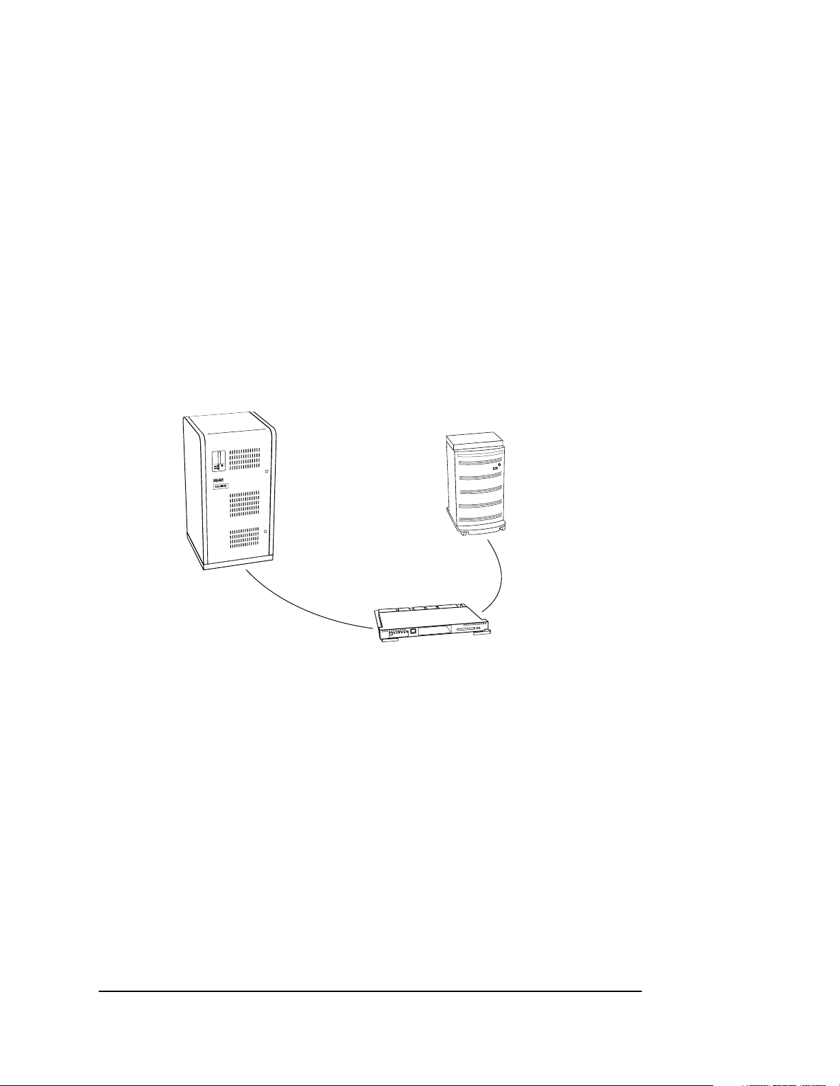
Your controller is the intelligent bridge between your host and the devices in your
subsystem.
1–7
Host
Controller
Figure 1–2. Bridging the Gap Between the Host and Its Storage Subsystem
Storage
subsystem
CXO5505A
The controller shown in Figure 1–2 is an integral part of any storage subsystem
because it provides a host with high-performance and high-availability access to
storage devices. See the HSZ80 Array Controller ACS Version 8.3 Release Notes for
the most recent list of supported devices and operating systems.
The controller provides the ability to com bin e several ordinary d isk drives into a
single, high-performance storage unit called a storageset. Storagesets are
implementations of RAID technology, which ensures that every unpartitioned
storageset, whether it uses two disk drives or ten, looks like a single storage unit to the
host. See Chapter 3 and Chapter 4 for more information about storagesets and how to
configure them.
Compaq HSZ80 Array Controller ACS Version 8.3 Configuration and CLI Reference Guide
Page 30

1–8 General Description
From the host’s perspective, the controller is simply another device connected to one
of its I/O buses. Consequently, the host sends its I/O requests to the controller just as
it would to any SCSI device. From the subsystem’s perspective, the controller
receives the I/O requests and directs them to the devices in the subsystem. Because
the controller processes the I/O requests, the host isn’t burdened by the processing
that’s typically associated with reading and writing data to multiple storage devices.
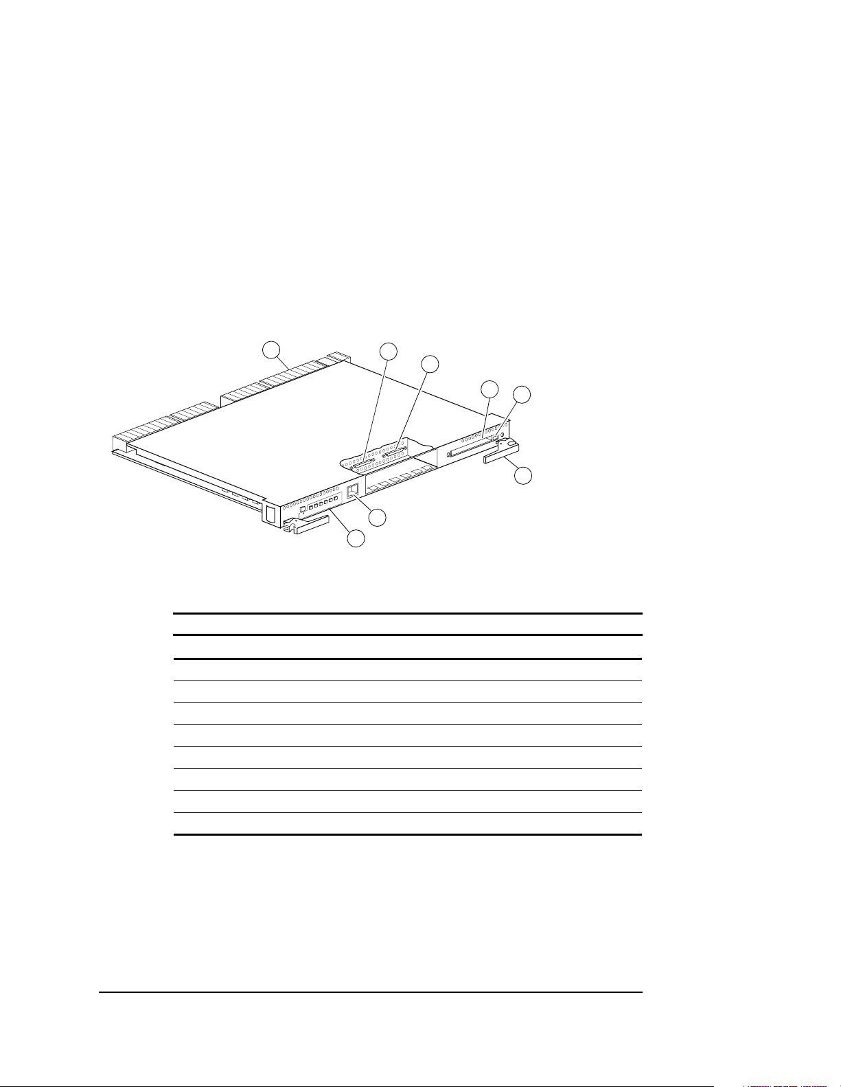
Figure 1–3 shows an HSZ80 Array Controller. Figure 1 –4 shows the parts used in
configuring it and Table 1–4 lists the descriptions and part numbers.
NOTE: The maintenance port cable shipped with the controller has a 9-pin
connector for a PC connection only. If you are using a terminal instead of a PC or if
you have a system with a DB25 connection, you can obtain a cable as shown in
Figure 1–5 on page 1–12 from the local field service office.
To determine which parts you need for your configuration, you must have an idea of
the type of configuration you will be running in y ou r subsystem. See the following
sections for your configuration type:
■ “Configuring a Single Controller,” page 2–5
■ “Configuring Dual-Redundant Controllers in Transparent Failover Mode,”
page 2–10
■ “Configuring Dual-Redundant Controllers in Multiple-Bus Failover Mode,”
page 2–16
The components that you’ll use most often are conveniently located on the
controller’s front panel, such as the maintenance port and the operator control panel
(OCP). The host port and program-card slot are also located on the front panel,
making it easy to update the controller’s software or to connect the controller to a
different host.
Page 31
1–9
1
1 2 3 4 5 6
2
7
8
Figure 1–3. HSZ80 Array Controller
Table 1–3 HSZ80 Array Controller
Item Description
➀
➁
➂
➃
➄
➅
➆
➇
Backplane connector
Host port 1
Host port 2
Program card slot
Program card ejection button
Release lever
Maintenance port
Operator Control panel
3
4
5
6
CXO6284B
Compaq HSZ80 Array Controller ACS Version 8.3 Configuration and CLI Reference Guide
Page 32

1–10 General Description
1
1 2 3 4 5 6
Figure 1–4. Parts Used in Configuring the HSZ80 Array Controller
2
3
4
5
6
7
10
8
9
CXO6492B
Table 1–4 Description of Parts
Item Description
➀
➁
➂
➃
➄
➅
Host port 1
Host port 2
ESD/PCMCIA program card
ESD/PCMCIA program card cover
Trilink connectors
Host bus cable
Page 33

Table 1–4 Description of Parts (Continued)
Item Description
➆
➇
➈
➉
Ferrite bead
Terminator
Jumper cable
Maintenance port cable
1–11
Compaq HSZ80 Array Controller ACS Version 8.3 Configuration and CLI Reference Guide
Page 34

1–12 General Description
1
Figure 1–5. Optional Maintenance Port Cable for a Terminal Connection
Item Description
➀
➁
➂
➃
➄
2
3
4
5
CXO6505B
Table 1–5 Parts of the Optional Maintenance Port Cable
Cable assembly
Ferrite bead
RJ-11 Adapter
RJ-11 Extension Cable
PC Serial Port Adapter
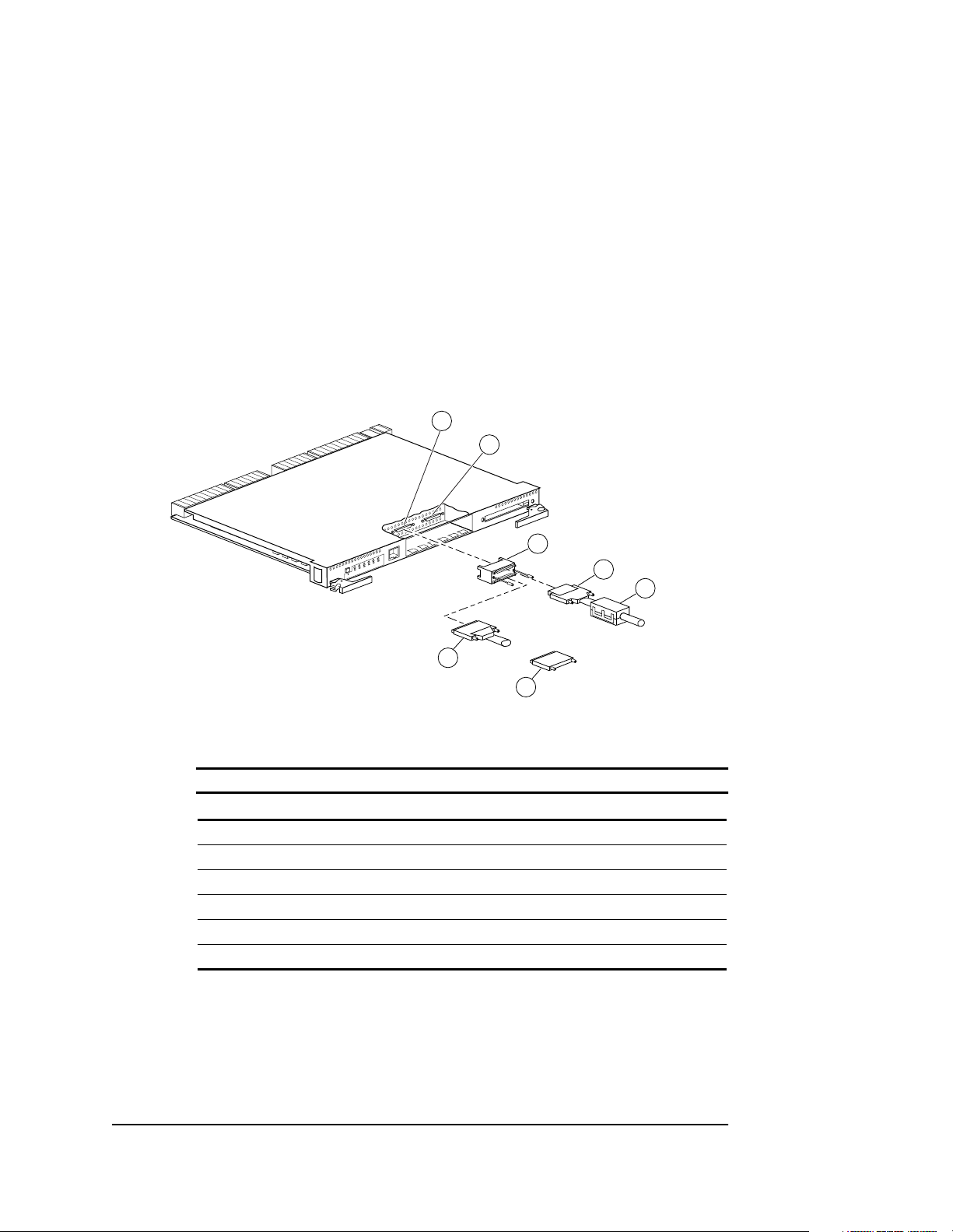
Each controller is supported b y its own cache module. Figure 1–6 shows which cache
module supports which controller in a dual-redundant controller configuration in a
BA370 rack-mountable enclosure.
Page 35
1–13
EMU
Controller A
Controller B
Cache module A Cache module B
Figure 1–6. Location of Controllers and Cache Modules
IMPORTANT: Compaq recommends that you use the slots for controller A and
cache module A for single controller configurations. Slot A responds to SCSI target ID number 7 on the device buses and slot B responds to SCSI target ID number 6 on the device buses.
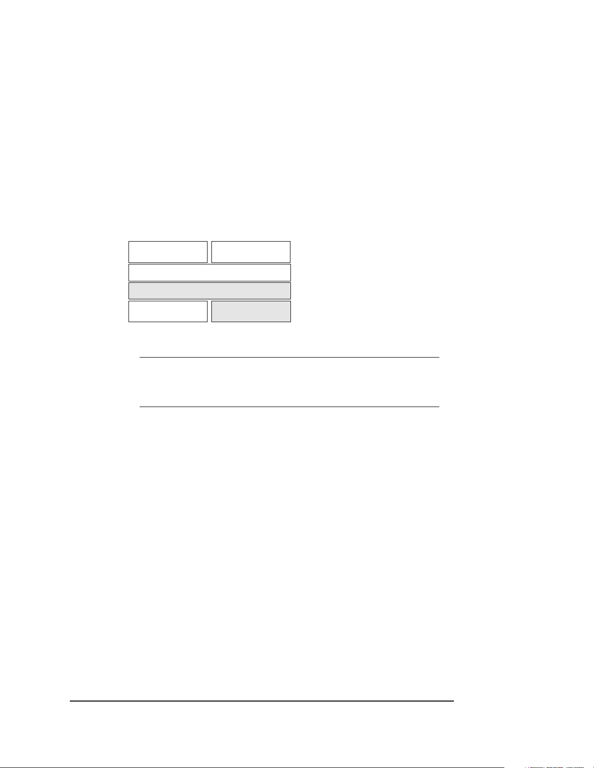
Operator Control Panel
The operator control panel (OCP ) co nt ains a res et button and six port button LEDs as
shown in Figure 1–7. The reset button flashes about once per second to indicate that
the controller is operating normally. The port button LEDs correspond to the
controller’s device ports and remain off during normal operation. If an error occurs,
the reset button and LEDs will illuminate in a solid or flashing pattern to help you
diagnose the problem.
PVA
CXO6283A
Compaq HSZ80 Array Controller ACS Version 8.3 Configuration and CLI Reference Guide
Page 36

1–14 General Description
Reset button/
LED
123456
Figure 1–7. HSZ80 Controller Operator Control Panel (OCP)
Port button/
LED
CXO6216A
See Figure 1–3 on page 1–9 for the location of the OCP on the HSZ80 Array
Controller.
Under normal circumstances, you will not need to remove the controller from its
enclosure. For this reason, the components that you will use most often are
conveniently located on the front panel. For example, the maintenance port pro vides a
convenient way to connect a PC or term inal to yo ur con troller so that you can inter act
with it.
After you conf igure you r contro ller , you shou ld period ically ch eck its co ntrol pan el. If
an error occurs, one or more of the LEDs on the control panel will flash in a pattern
that will help you to diagnose the problem. See the HSZ80 Array Controller ACS
Version 8.3 Maintenance and Service Guid e for details about troubleshooting yo ur
controller.
Maintenance Port
You can access the controller in two ways: through a PC or terminal via the
maintenance port or through a remote terminal—sometimes called a virtual terminal
or host console—via the host. Compaq recommends that you use a PC or terminal to
carry out the troubleshooting and se rvicing procedures in this manual. See
“Establishing a Local Conn ection to t he Controll er ,” page 2–26, for more information
about connecting the controller with a maintenance port cable.
Page 37

Utilities and Exercisers
The controller’s software includes the following utilities and exercisers to assist in
troubleshooting and maintaining the controller and the other modules that support its
operation. For more details on each of the utilities and exercisers, see the HSZ80
Array Controller ACS Version 8.3 Maintenance and Service Guide.
Fault Management Utility
The Fault Management Utility (FMU) provides a limited interface to the controller’s
fault management system. As a troubleshooting tool, you can use FMU to:
■ Display the last-failure and memory-system-failure entries that the fault
management software stores in the controller’s nonvolatile memory.
■ Translate many of the event messages that are contained in the entries related to
the significant events and failures. For example, entries may contain codes that
indicate the cause of the event, the software component that reported the event,
the repair action, and so on.
■ Set the display characteristics of spontaneous events and failures that the fault
management system sends to the PC or terminal, or to the host.
1–15
Virtual Terminal Display
Use the virtual terminal display (VTDPY) utility to aid in troubleshooting the
following issues:
■ Communication between the controller and its hosts.
■ Communication between the controller and the devices in the subsystem.
■ The state and I/O activity of the logical units, devices, and device ports in the
subsystem.
Compaq HSZ80 Array Controller ACS Version 8.3 Configuration and CLI Reference Guide
Page 38

1–16 General Description
Disk Inline Exerciser
Use the disk inline exerciser (DILX) to investigate the data-transfer capabilities of
disk drives. DILX tests and verifies operation of the controller and the SCSI–2 disk
drives attached to it. DILX generates intense read and write loads to the disk drive
while monitoring the drive’s performance and status.
Configuration Utility
Use the configuration (CONFIG) utility to add one or more storage devices to the
subsystem. This utility checks the device ports for new disk drives, then adds them to
the controller’s configuration and automatically names them.
HSUTIL
Use HSUTIL to upgrade the firmware on disk drives in the subsystem and to format
disk drives.
Code Load and Code Patch Utility
Use the Code Load/Code Patch (CLCP) utility to upgrade the controller software and
the EMU software. You can also use it to patch the controller software. Whenever you
install a new controller , you must hav e the correct software v ersion and patch number.
IMPORTANT: Only Compaq field service personnel are authorized to upload EMU
microcode updates. Contact the Customer Service Center (CSC) for directions in
obtaining the appropriate EMU microcode and installation guide.
Clone Utility
Use the Clone utility to duplicate the data on any unpartitioned mirrorset. Back up the
cloned data while the actual storageset remains online.
Page 39

1–17
Field Replacement Utility
Use the field replacement utility (FRUTIL) to replace a failed controller (in a dualredundant configuration) without shutting down the subsystem.You can also use this
menu-driven utility to replace cache modules, external cache batteries, and the PVA
module.
Change Volume Serial Number Utility
Only Compaq authorized service personnel may use th is utility.
The Change Volume Serial Number (CHVSN) utility generates a new volume serial
number (called VSN) for the specified device and writes it on the media. It is a w ay to
eliminate duplicate volume serial numbers and to rename duplicates with different
volume serial numbers.
Device Statistics Utility
The Device Statistics (DSTAT) utility allows you to log I/O activity on a controller
over an extended period of time. Later, you can analyze that log to determine where
the bottlenecks are and how to tune the controller for optimum performance.
Compaq HSZ80 Array Controller ACS Version 8.3 Configuration and CLI Reference Guide
Page 40

1–18 General Description
Cache Module
Each controller requires a companion cache module as shown in Figure 1–8.
Table 1–7 lists the descriptions and part numbers of the cache module. Figure 1–6 on
page 1–13 shows the location of a controller’s companion cache module.
The cache module, which contains up to 512 MB of memory, increases the
subsystem’s I/O performance by providing read, read-ahead, write-through, and
write-back caching. The size of the memory contained in the cache module depends
on the configuration of the DIMMs, with the support e d combinations shown in
Table 1–6. For placement of the DIMMs, see the HSZ80 Array Controller ACS
Version 8.3 Maintenance and Service Guid e.
32 MB 2 64 MB
32 MB 4 128 MB
128 MB 2 256 MB
128 MB 4 512 MB
Table 1–6 Cache Module Memory Configurations
DIMMs Quantity Memory
Page 41

5
4
Figure 1–8. Cache Module
Item Description
1–19
1
~
2
3
CXO6306B
Table 1–7 Location of Cache Module Parts
➀
➁
➂
➃
➄
Cache memory power LED
ECB Y cable
Release lever
Backplane connector
DIMM
Compaq HSZ80 Array Controller ACS Version 8.3 Configuration and CLI Reference Guide
Page 42

1–20 General Description
Caching Techniques
The cache module supports the following caching techniques to increase the
subsystem’s read and write performance:
■ Read caching
■ Read-ahead caching
■ Write-through caching
■ Write-back caching
Read Caching
When the controller receives a read request from the host, it reads the data from the
disk drives, delivers it to the host, and also stores the data in its cache module. This
process is called read caching.
Read caching can decrease the subsystem’s response time to many of the host’s read
requests. If the host requests some or all of the cached data, the controller satisf ies the
request from its cache module rather than from the disk drives. By default, read
caching is enabled for all storage units.
To set the maximum cache that can be transferred, see “SET unit-number” in
Chapter 5, “CLI Commands.”
Read-Ahead Caching
Read-ahead caching begins once the controller has already processed a read request
and it receives a sequential read request from the host. If the controller does not find
the data in the cache memory, it reads the data from the disks and sends it to the cache
memory .
Page 43

1–21
The controller then anticipates subsequent read requests and begins to prefetch the
next blocks of data from the di sk s as it sends th e reques t ed read data to the ho st. Thi s
is a parallel action. The controller notifies the host of the read completion, and
subsequent sequential read requests are satisfied through the cache memory. By
default, read-ahead caching is enabled for all disk units.
Write-Through Caching
When the controller receives a write request from the host, it stores the data in its
cache module, writes the data to the disk drives, then notifies the host when the write
operation is complete. This process is called write-through caching because the data
actually passes through—and is stored in—the cache memory on its way to the disk
drives.
If you enable read caching for a storage unit, write-through caching is automatically
enabled. Likewise, if you disable read caching, write-through caching is
automatically disabled.
Write-Back Caching
This caching technique decreases the subsystem’s response time to write requests by
allowing the controller to declare the write operation “complete” as soon as the data
reaches its cache memory. The controller performs the slower operation of writing the
data to the disk drives at a later time.
By default, write-back caching is enabled for all disk units. In either case, the
controller will not provide write-back caching to a unit unless the cache memory is
nonvolatile, as described in the next section.
If the mirrorset is a disaster-tolerant mirrorset, then write-back caching cannot be
enabled.
Compaq HSZ80 Array Controller ACS Version 8.3 Configuration and CLI Reference Guide
Page 44

1–22 General Description
Fault-Tolerance for Write-Back Caching
The cache module supports nonvolatile memory and dynamic cache policies to
protect the availability of its unwritten (write-back) data.
Nonvolatile Memory
Except for disaster-tolerant supported mirrorsets, the controller can provide write-
back caching for storage units as long as the controller’s cache memory is nonv olatile.
In other words, to enable write-back caching, you must provide a backup power
source to the cache module to preserve the unwritten cache data in the event of a
power failure. If the cache memory were volatile—that is, if it didn’t have a backup
power supply—the unwritten cache data would be lost during a power failure.
By default, the controller expects to use an ECB as the backup power source for its
cache module. See “External Cache B attery,” page 1–29, for more information on the
ECB.
However, if your subsy stem is backed up by an uninterruptible power supply (UPS),
you can tell the controller to use the UPS as the backup power source with the
command, SET Controller, and using the CACHE_UPS switch.
Cache Policies Resulting from Cache Module Failures
If the controller detects a full or partial failure of its cache module or ECB, it
automatically reacts to preserve the unwritten data in its cache module. Depending
upon the severi ty of the f ailur e, the co ntroller choo ses an interim cach ing techn ique—
also called the cache policy—which it uses until you repair or replace the cache
module.
Table 1–8 shows the cache policies resulting from a full or partial failure of cache
module A in a dual-redundant controller configuration. The consequences shown in
this table are the same for cache module B.
Page 45

Table 1–9 shows the cache policies resulting from a full or partial failure of cache
module A’s ECB in a dual-redundant controller configuration . When cache module A
is at least 50% charged, the ECB is still good and is charging. When it is less than
50% charged, the ECB is low, but still charging. The consequences shown are the
opposite for a failure of cache module B’s ECB.
Table 1–8 Cache Policies and Cache Module Status
Cache Module Status Cache Policy
Cache A Cache B Unmirrored Cache Mirrored Cache
1–23
Good Good Data loss: No.
Cache policy: Both controllers
support write-back caching.
Failover: No.
Multibit
cache
memory
failure
Good Data loss: Forced error and loss of
write-back data for which the
multibit error occurred. Controller A
detects and reports the lost blocks.
Cache policy: Both controllers
support write-back caching.
Failover: No.
Data loss: No.
Cache policy: Both controllers support
write-back caching.
Failover: No.
Data loss: No. Controller A recovers its
lost write-back data from the mirrored
copy on cache B.
Cache policy: Both controllers support
write-back caching.
Failover: No.
Compaq HSZ80 Array Controller ACS Version 8.3 Configuration and CLI Reference Guide
Page 46

1–24 General Description
Table 1–8 Cache Policies and Cache Module Status (Continued)
Cache Module Status Cache Policy
Cache A Cache B Unmirrored Cache Mirrored Cache
DIMM or
cache
memory
controller
chip
failure
Good Data integrity: Write-back data that
was not written to media when
failure occurred was not recovered.
Cache policy: Controller A supports
write-through caching only;
controller B supports write-back
caching.
Failover: In transparent failover, all
units failover to controller B. In
multiple-bus failover with hostassist, only those units that use
write-back caching, such as
RAIDsets and mirrorsets, failover to
controller B. All units with lost data
become inoperative until you clear
them with the CLEAR LOST_DATA
command. Units that didn’t lose data
operate normally on controller B.
In single controller configurations,
RAIDsets, mirrorsets, and all units
with lost data become inoperative.
Although you can clear the lost data
errors on some units, RAIDsets and
mirrorsets remain inoperative until
you repair or replace the nonvolatile
memory on cache A.
Data integrity: Controller A recovers all
of its write-back data from the
mirrored copy on cache B.
Cache policy: Controller A supports
write-through caching only; controller
B supports write-back caching.
Failover: In transparent failover, all
units failover to controller B and
operate normally. In multiple-bus
failover with host-assist, only those
units that use write-back caching,
such as RAIDsets and mirrorsets,
failover to controller B.
Page 47
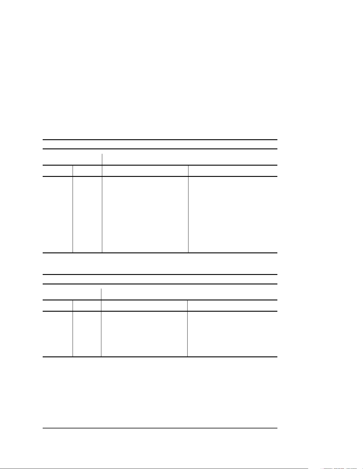
Table 1–8 Cache Policies and Cache Module Status (Continued)
Cache Module Status Cache Policy
Cache A Cache B Unmirrored Cache Mirrored Cache
1–25
Cache
Board
Failure
Good Same as for DIMM failure. Data integrity: Controller A recovers all
of its write-back data from the
mirrored copy on cache B.
Cache policy: Both controllers support
write-through caching only. Controller
B cannot execute mirrored writes
because cache module A cannot
mirror controller B’s unwritten data.
Failover: No.
Table 1–9 Resulting Cache Policies and ECB Status
Cache Module Status Cache Policy
Cache A Cache B Unmirrored Cache Mirrored Cache
At least
50%
charged
At least
50%
charged
Data loss: No.
Cache policy: Both controllers
continue to support write-back
caching.
Failover: No.
Data loss: No.
Cache policy: Both controllers continue
to support write-back caching.
Failover: No.
Compaq HSZ80 Array Controller ACS Version 8.3 Configuration and CLI Reference Guide
Page 48

1–26 General Description
Table 1–9 Resulting Cache Policies and ECB Status (Continued)
Cache Module Status Cache Policy
Cache A Cache B Unmirrored Cache Mirrored Cache
Less than
50%
charged
At least
50%
charged
Data loss: No.
Cache policy: Controller A supports
write-through caching only;
controller B supports write-back
caching.
Failover: In transparent failover, all
units failover to controller B.
In multiple-bus failover with hostassist, only those units that use
write-back caching, such as
RAIDsets and mirrorsets, failover to
controller B.
In single-controller configurations,
the controller only provides writethrough caching to its units.
Data loss: No.
Cache policy: Both controllers continue
to support write-back caching.
Failover: No.
Page 49

Table 1–9 Resulting Cache Policies and ECB Status (Continued)
Cache Module Status Cache Policy
Cache A Cache B Unmirrored Cache Mirrored Cache
1–27
Failed At least
50%
charged
Less than
50%
charged
Less than
50%
charged
Data loss: No.
Cache policy: Controller A supports
write-through caching only;
controller B supports write-back
caching.
Failover: In transparent failover, all
units failover to controller B and
operate normally.
In multiple-bus failover with hostassist, only those units that use
write-back caching, such as
RAIDsets and mirrorsets, failover to
controller B.
In single-controller configurations,
the controller only provides writethrough caching to its units.
Data loss: No.
Cache policy: Both controllers
support write-through caching only.
Failover: No.
Data loss: No.
Cache policy: Both controllers continue
to support write-back caching.
Failover: No.
Data loss: No.
Cache policy: Both controllers support
write-through caching only.
Failover: No.
Compaq HSZ80 Array Controller ACS Version 8.3 Configuration and CLI Reference Guide
Page 50

1–28 General Description
Table 1–9 Resulting Cache Policies and ECB Status (Continued)
Cache Module Status Cache Policy
Cache A Cache B Unmirrored Cache Mirrored Cache
Failed Less than
50%
charged
Failed Failed Data loss: No.
Data loss: No.
Cache policy: Both controllers
support write-through caching only.
Failover: In transparent failover, all
units failover to controller B and
operate normally.
In multiple-bus failover with hostassist, only those units that use
write-back caching, such as
RAIDsets and mirrorsets, failover to
controller B.
In single-controller configurations,
the controller only provides writethrough caching to its units.
Cache policy: Both controllers
support write-through caching only.
Failover: No. RAIDsets and mirrorsets
become inoperative. Other units that
use write-back caching operate with
write-through caching only.
Data loss: No.
Cache policy: Both controllers support
write-through caching only.
Failover: No.
Data loss: No.
Cache policy: Both controllers support
write-through caching only.
Failover: No. RAIDsets and mirrorsets
become inoperative. Other units that
use write-back caching operate with
write-through caching only.
Page 51

External Cache Battery
To preserve the write-back cache data in the event of a primary power failure, a cache
module must be connected to an ECB or a UPS.
Compaq supplies two versions of ECBs: a single-battery ECB for single controller
configurations, and a dual-battery ECB for dual-redundant controller configurations,
which is shown in Figure 1–9. When the batteries are fully charged, an ECB can
preserve 512 MB of cache memory for 24 hours. However, the battery capacity
depends upon the size of memory contained in the cache module, which are listed in
Table 1–10.
Table 1–10 ECB Capacity Based on Memory Size
Size DIMM Combinations Capacity
64 MB Two, 32 MB each 96 hours
128 MB Four, 32 MB each 48 hours
256 MB Two, 128 MB each 48 hours
512 MB Four, 128 MB each 24 hours
1–29
Compaq HSZ80 Array Controller ACS Version 8.3 Configuration and CLI Reference Guide
Page 52

1–30 General Description
Figure 1–9. ECB for Dual-Redundant Controller Configurations
CACHE
POWER
STATUS
SHUT OFF
1
SHUT OFF
STATUS
POWER
CACHE
2
4
~
CXO6305B
Table 1–11 Location of Parts
3
Item Description
➀
➁
➂
➃
Shut off button
Status LED
ECB Y cable
Male port
Page 53

Charging Diagnostics
Whenever you restart the controller, its diagnostic routines automatically check the
charge in the ECB’s batteries. If the batteries are fully charged, the controller reports
them as fully charged and recheck s them every 24 hour s. If the b atteries are ch arging,
the controller rechecks them every 4 minutes. Batteries are reported as being either
above or below 50 percent in capacity. Batteries below 50 percent in capacity are also
referred to as being low.
This 4-minute pollin g continues fo r up to 10 ho urs—the maximum time it shoul d take
to recharge the batteries. If the batteries have not been charged sufficiently after 10
hours, the controller declares them to be failed.
Battery Hysteresis
When charging a battery, write-back caching will be allowed as long as a previous
down time has not drained more than 50 percent of a battery’s capacity. When a
battery is operating below 50 percent capacity, the battery is considered to be low and
write-back caching is disabled.
CAUTION: Compaq recommends that you replace the ECB every two
years to prevent battery failure.
1–31
IMPORTANT: If a UPS is used for backup power, the controller does not check
the battery. To set the subsystem to use a UPS or to instruct the controller on per-
forming regular battery checks, see “SET controller” in Chapter 5, “CLI Commands.”
Compaq HSZ80 Array Controller ACS Version 8.3 Configuration and CLI Reference Guide
Page 54

Page 55

Chapter 2
Configuring an HSZ80 Array Controller
This chapter explains how to configure an HSZ80 Array Controller and the modules
that support its operation in a StorageWorks subsystem.
2–1
Compaq HSZ80 Array Controller ACS Version 8.3 Configuration and CLI Reference Guide
Page 56

2–2 Configuring an HSZ80 Array Controller
Introduction
Use the Quick Setup Guide that came with your subsystem to unpack and set up your
subsystem prior to configuring your controller.
Unless you specifically requested a preconfigured subsystem, you will have to
configure your controller and its subsystem before you can use them. Use the
procedure in this chapter to configure your controller. The procedure contains
references to more detailed information, should you need it.
For the complete syntax and descriptions of the CLI commands used in the
configuration procedure, see Chapter 5, “CLI Commands.”
Configuration Rules
Before you configure your controller, review these configuration rules and ensure
your planned configuration meets the following requirements and conditions:
■ Maximum 15 targets with up to 32 LUNs on each target, depending on the
operating system
❏ Maximum 128 assignable, host-visible LUNs acros s all 15 targets
■ Maximum 512-GB LUN capacity
■ Maximum 72 physical devices
■ Maximum 20 RAID-5 storagesets
■ Maximum 30 RAID-5 and RAID-1 storagesets
■ Maximum 45 RAID-5, RAID-1, and RAID-0 storagesets
■ Maximum 8 partitions per storages et or individual disk
■ Maximum 6 members per mirrorset
■ Maximum 14 members per RAID-5 storageset
■ Maximum 24 members per stripeset
■ Maximum 48 physical devices per striped mirrorset
Page 57

Configuring an HSZ80 Array Controller
You can use this procedure to configure yo ur controller i n one of three conf ig urations:
1) single controller, 2) dual controllers in transparent failover mode, or 3) dual
controllers in multiple-bus failover (host-assisted) mode. When you are done
configuring the controller, you can then add devices, plan storagesets, and configure
storagesets. These tasks can be performed either with SWCC or using CLI co mmands
from a PC or terminal.
See the following sections for your configuration type:
■ “Configuring a Single Controller,” page 2–5
■ “Configuring Dual-Redundant Controllers in Transparent Failover Mode,”
page 2–10
■ “Configuring Dual-Redundant Controllers in Multiple-Bus Failover Mode,”
page 2–16
A Few Tips
As you configure the controller, keep these points in mind:
■ Cabling—You can either configure the controller with a maintenance port cable
and no SCSI host bus cables connected to the h ost, or you can co nfigure with the
SCSI host bus cables connected:
❏ SWCC—You can configure the controller using the SWCC graphical user
interface. See the Command Co ns ol e for HSZ 80 Sol u tio ns Gett ing Started Guide
for more details.
❏ CLI Commands—You can configure the controller with CLI commands
using a terminal program.
2–3
NOTE: Eventually, you must connect the SCSI host bus cables between the
controllers and the host. You can connect the SCSI host bus cables after
configuring the controllers using a maintenance port cable.
■ EMU Alarm Control Switch—If the EMU alarm goes off, simply press it to stop
it. Check the error message to verify the type of error condition.
Compaq HSZ80 Array Controller ACS Version 8.3 Configuration and CLI Reference Guide
Page 58

2–4 Configuring an HSZ80 Array Controller
■ CLI Commands—A few commands can be used while configuring the controller:
❏ CLEAR_ERRORS CLI—Clears all error messages so you can type without the
messages being repeated. Make sure you read each error m essage before deleting
it.
❏ SHOW THIS_CONTROLLER FULL and SHOW OTHER_CONTROLLER FULL—Lists
the full information about the controller.
Page 59
Configuring a Single Controller
1 2 3 4 5 6
2–5
1
2
3
4
5
4
Figure 2–1. Cabling for a Single-Controller Configuration
Table 2–1 Location of Parts for a Single Controller Configuration
Item Description
➀
➁
➂
➃
➄
➅
Host port 1
Host port 2
Trilink connector
Host bus cable
Ferrite bead
Terminator
or
6
CXO6285B
Compaq HSZ80 Array Controller ACS Version 8.3 Configuration and CLI Reference Guide
Page 60

2–6 Configuring an HSZ80 Array Controller
Follow these steps to configure a controller:
NOTE: This procedure has been written for first-time configuring. However, you
can adapt the procedure when you reconfigure the controllers. For replacing and
upgrading the controllers, see the
Maintenance and Service Guide
1. Use the power-verificati on and addressing (PVA) module ID switch to set the
SCSI ID number for the BA370 rack-mountable enclosure.
See “Setting the PVA Module ID Switch,” page 2–25, for details about PVA switch
settings.
2. Remove the program card ESD cover, and insert the program card into the
controller. Replace the ESD cover.
3. Turn on the power to the enclosure or cabinet by turning on the ac input boxes.
4. Establish a local connection to the controller.
See “Establishing a Local Connection to the Controller,” page 2–26, for details about
creating a local connection.
5. Set the SCSI target ID numbers for the controller. Use the following commands:
SET THIS_CONTROLLER PORT_1_ID = (
HSZ80 Array Controller ACS Version 8.3
.
n,n
)
or
n,n
SET THIS_CONTROLLER PORT_2_ID = (
See “Setting SCSI Target ID Numbers,” page 2–33, for details about val id SCSI tar get
ID numbers.
)
Page 61

2–7
6. Set the host function mode for the controller using the target ID numbers set in
step 5. Use the following command:
NOTE: The default host function mode defaults to Host Mode A. The
HOST_FUNCTION switch changes the host function mode to a different mode.
SET THIS_CONTROLLER HOST_FUNCTION= (
ID, MODE
)
To change the host function mode, see “SET controller,” page 5–91 for information
on the HOST_FUNCTION switch.
7. Restart the controller using the following command:
RESTART THIS_CONTROLLER
See “RESTART controller” in Chapter 5, “CLI Commands.”
8. Set the time on the controller, which provides a baseline for replacing the
external battery, using the following command:
SET THIS_CONTROLLER TIME=DD-MMM-YYYY:HH:MM:SS
NOTE: All values are numbers, except for MMM, which uses the first three
letters of the month. When setting hours, minutes, and seconds—HH, MM,
and SS—you must use 24-hour time.
9. Set up the battery discharge timer:
a. Start Fru til using the following command:
RUN FRUTIL
Frutil displays the following:
Do you intend to replace this controller’s cache battery? Y/N
b. Enter Y(es).
Frutil displays a three-step procedure and prompts you to press return.
c. Press return.
Compaq HSZ80 Array Controller ACS Version 8.3 Configuration and CLI Reference Guide
Page 62

2–8 Configuring an HSZ80 Array Controller
10. Enter any other optional CLI commands for your configuration.
See “Optional Steps,” page 2–22 and Chapter 5, “CLI Commands.”
11. Display details about the controller you configured. Use the following command:
SHOW THIS_CONTROLLER FULL
See “SHOW” in Chapter 5, “CLI Commands.”
IMPORTANT: If you are using a PC or terminal with the maintenance port cable,
you must connect the SCSI bus cables in the desired configuration. See “Connecting a Single Controller to the Host,” page 2–9,for more information about
configurations.
Page 63

Connecting a Single Controller to the Host
Follow these steps and Figure 2–1 to connect a single, nonredundant controller to the
host:
1. Configure the controller. See “Configuring a Single Controller,” page 2–5.
2. Ensure the host and adapter are also configured. See the host user’s guide for
details.
3. Connect a trilink to the controller going into host Po rt 1:
a. Co nnect the host bus cable onto one end of the trilink connector.
b. For a BA370 enclosure residing in an SW600 cabinet, snap the ferrite bead
on the bus cable within one inch of the controller.
4. Connect a terminator on the trilink connector for host Port 1:
a. If the controller is at the end of the host bus, connect a terminator to the other
connector on the front of the trilink connector.
b. Otherwise, connect a cable that continues to the next device on the bus. Be
sure to install a terminator at the end of the bus.
5. Repeat steps 3 and 4 for host Port 2.
2–9
IMPORTANT: The HSZ80 Array Controller has dual-host ports, Port 1 and Port 2,
which may be configured at the same time. The configuration in Figure 2–1 only
shows a connection to host Port 1. However, you may also configure host Port 2
the same way, depending on your system requirements.
Compaq HSZ80 Array Controller ACS Version 8.3 Configuration and CLI Reference Guide
Page 64
2–10 Configuring an HSZ80 Array Controller
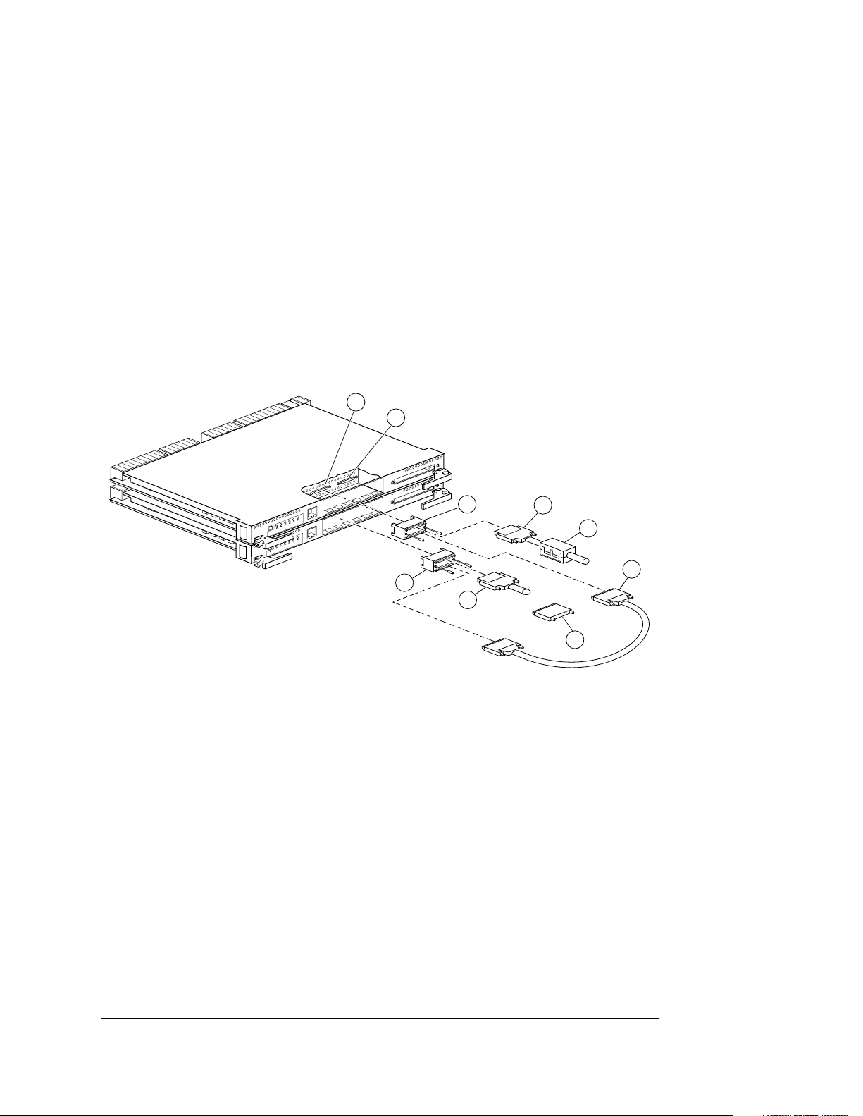
Configuring Dual-Redundant Controllers in Transparent Failover Mode
1
2
3
1 2 3 4 5 6
1 2 3 4 5 6
3
4
4
5
or
6
CXO6287B
Figure 2–2. Cabling for a Dual-Redundant Controller Configuration in Transparent Failover
7
Page 65

Table 2–2 Location of Parts for Transparent Failover
Item Description
➀
➁
➂
➃
➄
➅
➆
Follow these steps to configure a controller:
NOTE: This procedure has been written for first-time configuring. However, you
can adapt the procedure when you reconfigure the controllers. For replacing and
upgrading the controllers, see the
Maintenance and Service Guide
1. Use the power-verification and addressing (PVA) module ID switch to set the
SCSI ID number for the BA370 rack-mountable enclosure.
Host port 1
Host port 2
Trilink connector
Host bus cable
Ferrite bead
Terminator
Jumper cable
HSZ80 Array Controller ACS Version 8.3
.
2–11
See “Setting the PVA Module ID Switch,” page 2–25, for details about PVA switch
settings.
2. Remove the program card ESD cover, and insert the program card into the
controller. Replace the ESD cover. Repeat for the other controller.
3. Turn on the power to the enclosure or cabinet by turning on the ac input boxes.
4. Establish a local connection to the controllers.
See “Establishing a Local Connection to the Controller,” page 2–26, for details about
creating a local connection.
Compaq HSZ80 Array Controller ACS Version 8.3 Configuration and CLI Reference Guide
Page 66

2–12 Configuring an HSZ80 Array Controller
5. Put this controller into transparent failover mode. Use the following command:
CAUTION: Issuing the SET FAILOVER COPY command will overwrite
data on the companion controller. If you are reconfiguring the control-
lers, see “CONFIGURATION RESET” in Chapter 5, “CLI Commands,”
before proceeding and for more information.
SET FAILOVER COPY = THIS_CONTROLLER
The other controller inherits this controller’s configuration, then restarts. Wait for it to
return to normal operation before continuing.
See details about failover modes in “Selecting a Failover Mode,” page 2–29.
6. If you want to enable mirrored write-back cache in a failo v er conf igu ration, enter
this command:
SET THIS_CONTROLLER MIRRORED_CACHE
NOTE: Both controllers restart when you set mirror mode. This process can take
up to 5 minutes, depending on the amount of data that must be flushed from the
cache.
For details about caching techniques, see “Caching Techniques,” page 1–20.
For details about mirrored write-back cache, see “Enabling Mirrored Write-Back
Cache,” page 2–31.
7. Set the SCSI target ID numbers for the controller. Use the following command:
n,n
n,n
)
)
SET THIS_CONTROLLER PORT_1_ID= (
or
SET THIS_CONTROLLER PORT_2_ID= (
See “Setting SCSI Target ID Numbers,” page 2–33, for details about val id SCSI tar get
ID numbers.
Page 67

2–13
8. If you are configuring controllers in transparent f ailov er mod e, prefer some or all
SCSI target ID numbers to the controllers. Use the following command:
n, n
SET THIS_CONTROLLER PORT_1_PREFERRED_ID = (
)
or
n,n
SET THIS_CONTROLLER PORT_2_PREFERRED_ID = (
)
where n,n is a subset of the target ID numbers you declared in step 5.
See “Using Preferred ID Numbers,” page 2–35, for details about preferred SCSI
target ID numbers.
9. Set the host function mode for the controller using the target ID numbers set in
step 7 and in step 8. Use the following command:
NOTE: The default host function mode defaults to Host Mode A. The
HOST_FUNCTION switch changes the host function mode to a different mode.
SET THIS_CONTROLLER HOST_FUNCTION= (
ID, MODE
)
or
SET OTHER_CONTROLLER HOST_FUNCTION= (
ID, MODE
)
To change the host function mode, see “SET controller,” page 5–91 for information
on the HOST_FUNCTION switch.
10. Restart the controllers using the following command:
NOTE: After restarting the other controller, the EMU alarm will sound. To stop it,
restart this controller.
RESTART OTHER_CONTROLLER
RESTART THIS_CONTROLLER
See “RESTART controller” in Chapter 5, “CLI Commands.”
Compaq HSZ80 Array Controller ACS Version 8.3 Configuration and CLI Reference Guide
Page 68

2–14 Configuring an HSZ80 Array Controller
11. Set the time on the controller, which provides a baseline for replacing the
external battery, using the following command:
SET THIS_CONTROLLER TIME=DD-MMM-YYYY:HH:MM:SS
NOTE: All values are numbers, except for MMM, which uses the first three
letters of the month. When setting hours, minutes, and seconds—HH, MM,
and SS—you must use 24-hour time.
12. Set up the battery discharge timer:
a. Start Fru til using the following command:
RUN FRUTIL
Frutil displays the following:
Do you intend to replace this controller’s cache battery? Y/N
b. Enter Y(es).
Frutil displays a three-step procedure and prompts you to press return.
c. Press return.
13. Enter any other optional CLI commands for your configuration.
See the following section, “Optional Steps,” and Chapter 5, “CLI Commands.”
14. Display details about the controller you configured. Use the following command:
SHOW THIS_CONTROLLER FULL
See “SHOW” in Chapter 5, “CLI Commands.”
IMPORTANT: If you are using a PC or terminal with the maintenance port cable,
you must connect the SCSI bus cables in the desired configuration. See “Connecting in Transparent Failover Mode to the Host,” page 2–15,for more information about configurations.
Page 69

Connecting in Transparent Failover Mode to the Host
Use the following steps and Figure 2–2 t o connect a p air of du al-redundan t controlle rs
to the host:
1. Configure both controllers. See “Configuring Dual-Redundant Controllers in
Transparent Failover Mode,” page 2–10.
2. Ensure the host and adapter are also configured. See the host user’s guide for
details.
3. Connect two trilink connectors between both controllers going into host Port 1
with a jumper cable:
a. Attach one end of the jumper cable to one trilink.
b. Attach the other end of the jumper cable to the other trilink.
4. Connect the host bus cable onto one end of the trilink connector:
a. For a BA370 enclosure residing in an SW600 cabinet, snap the ferrite bead
on the bus cable within one inch of the controller.
5. Connect a terminator on the end of the trilink connector for host Port 1:
a. If the controller is at the end of the host bus, connect a terminator to the other
connector on the front of the trilink connector.
b. Otherwise, connect another host bus cable that continues to the next device
on the bus. Be sure to install a terminator at the end of the bus.
2–15
6. Repeat steps 3, 4, and 5 for host Port 2 on both controllers.
IMPORTANT: The HSZ80 Array Controller has dual-host ports, Port 1 and Port 2,
which may be configured at the same time. The configuration in Figure 2–2 only
shows a connection to host Port 1. However, you may also configure host Port 2
the same way, depending on your system requirements.
Compaq HSZ80 Array Controller ACS Version 8.3 Configuration and CLI Reference Guide
Page 70

2–16 Configuring an HSZ80 Array Controller
B
Configuring Dual-Redundant Controllers in Multiple-Bus Failover Mode
1
2
3
1 2 3 4 5 6
1 2 3 4 5 6
4
5
4
3
4
or
5
4
or
6
CXO6286
Figure 2–3. Cabling for a Dual-Redundant Controller Configuration in Multiple-Bus Failover
6
Page 71

Table 2–3 Location of Parts for Multiple-Bus Failover
Item Description
➀
➁
➂
➃
➄
➅
Follow these steps to configure a controller:
NOTE: This procedure has been written for first-time configuring. However, you
can adapt the procedure when you reconfigure the controllers. For replacing and
upgrading the controllers, see the
Maintenance and Service Guide
1. Use the power-verification and addressing (PVA) module ID switch to set the
SCSI ID number for the BA370 rack-mountable enclosure.
Host port 1
Host port 2
Trilink connector
Host bus cable
Ferrite bead
Terminator
HSZ80 Array Controller ACS Version 8.3
.
2–17
See “Setting the PVA Module ID Switch,” page 2–25, for details about PVA switch
settings.
2. Remove the program card ESD cover, and insert the program card into the
controller. Replace the ESD cover. Repeat for the other controller.
3. Turn on the power to the enclosure or cabinet by turning on the ac input boxes.
4. Establish a local connection to the controllers.
See “Establishing a Local Connection to the Controller,” page 2–26, for details about
creating a local connection.
Compaq HSZ80 Array Controller ACS Version 8.3 Configuration and CLI Reference Guide
Page 72

2–18 Configuring an HSZ80 Array Controller
5. Put this controller in multiple-bus failover mode, using the following command:
CAUTION: Issuing the SET MULTIBUS_FAILOVER COPY command will
overwrite data on the companion controller. If you are reconfiguring the
controllers, see “CONFIGURATION RESET” in Chapter 5, “CLI Commands,” before proceeding and for more information.
SET MULTIBUS_FAILOVER COPY = THIS_CONTROLLER
The other controller inherits this controller’s configuration, then restarts. Wait for it to
return to normal operation before continuing.
See “Selecting a Failover Mode,” page 2–29, for details about failover modes.
6. If you want to enable mirrored write-back cache in a failo v er conf igu ration, enter
this command:
SET THIS_CONTROLLER MIRRORED_CACHE
NOTE: Both controllers restart when you set mirror mode. This process can take
up to 5 minutes, depending on the amount of data that must be flushed from the
cache.
For details about caching techniques, see “Caching Techniques,” page 1–20.
For details about mirrored write-back cache, see “Enabling Mirrored Write-Back
Cache,” page 2–31.
7. Set the SCSI target ID numbers for the controller. Use the following command:
n,n
n,n
)
)
SET THIS_CONTROLLER PORT_1_ID= (
or
SET THIS_CONTROLLER PORT_2_ID= (
See “Setting SCSI Target ID Numbers,” page 2–33, for details about val id SCSI tar get
ID numbers.
Page 73

2–19
8. Set the host function mode for the controller using the target ID numbers set in
step 7. Use the following command:
NOTE: The default host function mode defaults to Host Mode A. The
HOST_FUNCTION switch changes the host function mode to a different mode.
SET THIS_CONTROLLER HOST_FUNCTION= (
ID, MODE
)
or
SET OTHER_CONTROLLER HOST_FUNCTION= (
ID, MODE
)
To change the host function mode, see “SET controller,” page 5–91 for information
on the HOST_FUNCTION switch.
9. Restart the controllers using the fo llowing comm a nd:
NOTE: After restarting the other controller, the EMU alarm will sound. To stop it,
restart this controller.
RESTART OTHER_CONTROLLER
RESTART THIS_CONTROLLER
See “RESTART controller” in Chapter 5, “CLI Commands.”
10. Set the time on the controller, which provides a baseline for replacing the
external battery, using the following command:
SET THIS_CONTROLLER TIME=DD-MMM-YYYY:HH:MM:SS
NOTE: All values are numbers, except for MMM, which uses the first three
letters of the month. When setting hours, minutes, and seconds—HH, MM,
and SS—you must use 24-hour time.
Compaq HSZ80 Array Controller ACS Version 8.3 Configuration and CLI Reference Guide
Page 74

2–20 Configuring an HSZ80 Array Controller
11. Set up the battery discharge timer:
a. Start Fru til using the following command:
RUN FRUTIL
Frutil displays the following:
Do you intend to replace this controller’s cache battery? Y/N
b. Enter Y(es).
Frutil displays a three-step procedure and prompts you to press return.
c. Press return.
12. Enter any other optional CLI commands for your configuration.
See the following section, “Optional Steps,” and Chapter 5, “CLI Commands.”
13. Display details about the controller you configured. Use the following command:
SHOW THIS_CONTROLLER FULL
See “SHOW” in Chapter 5, “CLI Commands.”
IMPORTANT: If you are using a PC or terminal with the maintenance port cable,
you must connect the SCSI bus cables in the desired configuration. See “Connecting in Multiple-Bus Failover Mode to the Host,” page 2–21,for more information about configurations.
Page 75

Connecting in Multiple-Bus Failover Mode to the Host
Use the following steps and Figure 2–3 to connect a pair of multiple-bus failover,
dual-redundant controllers to the host:
1. Configure both controllers. See “Configuring Dual-Redundant Controllers in
Multiple-Bus Failover Mode,” page 2–16.
2. Ensure the host and adapter are also configured. See the host user’s guide for
details.
3. Connect a trilink connector on host Port 1 or host Port 2 for one controller:
a. Connect the host bus cable onto one end of each trilink connector.
b. For a BA370 enclosure residing in an SW600 cabinet, snap the ferrite bead
on the bus cable within one inch of the controller.
4. Connect another trilink connector on host Port 1 or host Port 2 for a second
controller:
a. Con nect the hos t bus cable onto one end of each trilink connector.
b. For a BA370 enclosure residing in an SW600 cabinet, snap the ferrite bead
on the bus cable within one inch of the controller.
2–21
5. Connect a terminator on the end of each trilink connector:
a. If the controller is at the end of the host bus, connect a terminator to the other
connector on the front of the trilink connector.
b. Otherwise, connect another host bus cable that continues to the next device
on the bus. Be sure to install a terminator at the end of the bus.
Compaq HSZ80 Array Controller ACS Version 8.3 Configuration and CLI Reference Guide
Page 76

2–22 Configuring an HSZ80 Array Controller
6. Repeat steps 3, 4, and 5 for connecting a third and a fourth host bus.
IMPORTANT: The HSZ80 Array Controller has dual-host ports, Port 1 and Port 2,
which may be configured at the same time. The configuration in Figure 2–3
shows a two-bus connection going into host Port 1. However, you may also configure host Port 2 the same way, depending on your system requirements. For a
two-bus connection, the bus connections can occur on either host port on two
controllers. A third and fourth bus connection can also be made if three or four
buses are desired.
Optional Steps
You can perform these steps at any time during configuring.
Change the CLI prompt
Enter a 1- to 16-character string as the new prompt. For example, you could use the
prompt to indicate the controller’s name, such as “HSZ>.”
Type the following command:
SET THIS_CONTROLLER PROMPT = “new prompt”
If you are configuring dual-redundant controllers, also change the CLI prompt on the
other controller. Use the following command:
SET OTHER_CONTROLLER PROMPT = “new prompt”
See “SET controller” in Chapter 5, “CLI Commands.”
Page 77

2–23
Set the maximum data-transfer rate
Use the following command:
SET THIS_CONTROLLER PORT_1_TRANSFER_RATE_REQUESTED = speed
or
SET THIS_CONTROLLER PORT_2_TRANSFER_RATE_REQUESTED = speed
If you are configuring dual-redundant controllers, also set the transfer rate for the
other controller . Ho we ver , if you are running more t han one HSZ80 SCSI host port on
the same bus, you must set their transfer rates to be identical. Use the following
command:
SET OTHER CONTROLLER PORT_1_TRANSFER_RATE_REQUESTED=speed
or
SET OTHER CONTROLLER PORT_2_TRANSFER_RATE_REQUESTED=speed
See Chapter 5, “CLI Commands,” for more information about setting the data tran sfer
rate.
Compaq HSZ80 Array Controller ACS Version 8.3 Configuration and CLI Reference Guide
Page 78

2–24 Configuring an HSZ80 Array Controller
UPS Support
NOTE: By default, the controller expects to use an external cache battery (ECB) as
backup power to the cache module. You can instead choose to use an
uninterruptable power supply (UPS) to provide backup power in the event of a
primary power failure.
Use the following command:
SET THIS_CONTROLLER CACHE_UPS
If you are configuring dual-redundant controllers, also indicate that the other
controller’s power is supported by a UPS. Use the following command:
SET OTHER_CONTROLLER CACHE_UPS
The other controller inherits the cache UPS setting for this controller.
See “SET controller” in Chapter 5, “CLI Commands,” for details about set ting the
UPS.
See T abl e 1–8 on page 1–23 and T ab le 1–9 on page 1–25 for information about cache
policies.
Page 79

Setting the PVA Module ID Switch
The Power, Verification, and Addressing (PVA) module provides unique addresses to
extended subsystems. Each BA370 rack-mountable enclosure in an extended
subsystem must have its own PVA ID. Use PVA ID 0 for the enclosure that contains
the controllers. Use PVA IDs 2 and 3 for the additional enclosures. Figure 2–4
illustrates the PVA settings in an extended subsystem.
See the documentation that accompanied your enclosure for more details about the
PVA and its settings.
2–25
First Expansion
Enclosure
SCSI Target ID = 11
SCSI Target ID = 10
SCSI Target ID = 9
SCSI Target ID = 8
EMU
NOTE: SCSI target IDs 4 and 5 are reserved. IDs 6 and 7 are used by the controllers.
PVA 2
Master
Enclosure
SCSI Target ID = 3
SCSI Target ID = 2
SCSI Target ID = 1
SCSI Target ID = 0
EMU
Controller A
Controller B
PVA 0
Cache B Cache A
Second Expansion
SCSI Target ID = 15
SCSI Target ID = 14
SCSI Target ID = 13
SCSI Target ID = 12
Figure 2–4. SCSI Target ID Numbers on the Controller Device Bus and PVA Settings in an
Extended Subsystem
Enclosure
EMU
PVA 3
CXO5806B
Compaq HSZ80 Array Controller ACS Version 8.3 Configuration and CLI Reference Guide
Page 80

2–26 Configuring an HSZ80 Array Controller
Establishing a Local Connection to the Controller
You can communicate with a controller locally or remotely. Use a local connection to
configure the controller for the first time. Use a remote connection to your host
system for all subsequent configuration tasks. See the Quick Setup Guide that came
with your platform kit for details.
The maintenance port, as shown in Figure 2–5, provides a convenient way to connect
a PC or terminal to the controller so that you can troubleshoot and configure it. This
port accepts a standard RS-232 jack from any EIA-423 compatible terminal or a PC
with a terminal-emulation program. The maintenance port supports serial
communications with def a u lt values of 9600 baud using 8 data bits, 1 st op bi t , an d n o
parity.
The maintenance port cable shown in Figure 2–5 has a 9-pin connector molded onto
the end for a PC connection. If you need a terminal connection or a 25-pin
connection, optional cabling is available and can be ordered. See Figure 1–5 on
page 1–12 for an illustration.
Page 81

2–27
1 2 3 4 5 6
Maintenance
port
Maintenance
port cable
CXO6484A
Figure 2–5. PC/Terminal to Maintenance Port Connection
CAUTION: The maintenance port described in this book generates,
uses, and can radiate radio-frequency energy through cables that are
connected to it. This energy may interfere with radio and television
reception. Disconnect all maintenance port cables when you are not
communicating with the controller.
Follow these steps to establish a local connection for setting the controller’s initial
configuration:
1. Turn off the PC or terminal and connect it to the controller as shown in
Figure 2–6.
a. Plug the maintenance port cable into the maintenance port for a PC
connection.
Compaq HSZ80 Array Controller ACS Version 8.3 Configuration and CLI Reference Guide
Page 82

2–28 Configuring an HSZ80 Array Controller
b. If you are using a terminal instead of a PC, you can order a cable from the
local field service office as shown in figure 1-5.
2. Turn on the PC or term inal.
3. Configure the P C or ter minal for 9600 baud, 8 data bits, 1 stop bit , and no parity .
The default baud rate for the HSZ80 Array Controller is 9600, which makes
communication between the two compatible.
4. Press the Enter or Return key. A copyright notice and the CLI prompt appear,
indicating that you established a local connection with the controller.
5. Optional: Increase the data transfer rate to 19200 baud:
a. Set the controller to 19200 baud with one of the following commands:
SET THIS_CONTROLLER TERMINAL sPEED=19200
SET OTHER_CONTROLLER TERMINAL sPEED=19200
b. Configure the PC or terminal for 19200 baud.
When you are entering CLI commands in a dual-redundant controller configuration,
remember that the controller to which you ’ re conn ected is this controller and the oth er
controller is the “other controller” as shown in Figure 2–6.
Other controller
This controller
CXO5716A
Figure 2–6. “This Controller” and “Other Controller”
Page 83

Selecting a Failover Mode
In selecting a failover mode, you have two choices: transparent failover or multiplebus failover. If you want the failover to occur without any intervention from the host,
then transparent failover is best suited. The devices attached to the failed controller
fail over to the surviving controller. With multiple-bus failover, the host intervenes
during failover and sends commands to the companion controller.
Using Transparent Failover Mode
Transparent failover is a dual-redundant controller configuration in which two
controllers are connected to the same host and device buses. Use this configuration if
you want to use two controllers to service the entire group of storagesets, single-disk
units, and other storage devices. Because both controllers service the same storage
units, either controller can continue to service all of the unit s if its companion
controller fails.
Distribute the I/O load between the two controllers in a transparent failover
configuration using the following commands to specify which controller handles
which targets and units:
2–29
n,n
n,n
)
)
SET THIS_CONTROLLER PORT_1_PREFERRED_ID = (
or
SET THIS_CONTROLLER PORT_2_PREFERRED_ID = (
Keep the following tips in mind if you configure controllers for transparent failover:
■ Set your controller s for tr ansparent fai lo v er before conf ig uring de v ices. By doin g
this, devices, storagesets, and units added to one controller’s configuration are
automatically added to the other controller’s configuration.
■ If you decide to configure your devices before setting the controllers for
transparent failover, make sure you know which controller has the good
configuration information before specifying SET FAILOVER COPY command.
See Chapter 5 , “CLI Commands,” for details about setting the failover.
Compaq HSZ80 Array Controller ACS Version 8.3 Configuration and CLI Reference Guide
Page 84

2–30 Configuring an HSZ80 Array Controller
■ For better s ubsystem p erformance, balance y our assign ment of targ et ID numbers
across your dual-redundant pair of controlle rs. For example, if you are presenting
four targets to the host, prefer two to one controller and two to the other
controller.
■ Balance your assignment of devices. For example, in an 18-device subsystem,
place 3 devices on each of the 6 ports, rather than placing 6 devices on each of 3
ports.
■ The controller to which you copy configuration information restarts after you
enter the SET FAILOVER command.
Using Multiple-Bus Failover Mode
Multiple-bus (or host-assisted) failover is a dual-redundant controller configuration in
which each controller has its own connection to the host. Thus, if one of the host
connections to a controller fails, the host can cause units that became inaccessible to
failover to the remaining viable connection. Because both controllers service the same
storage units, either controller can continue to service all of the units if the other
controller fails.
Keep the following points in mind when configuring controllers for multiple-bus
failover:
■ The host distributes the I/O load between the controllers.
■ The host must have two SCSI adapters as well as operating-system software to
support the multiple-bus failover, dual-redundant controller configuration.
■ SCSI target ID number and LUN configurations on each controller must be
identical.
■ Mount both controllers in the same BA 37 0 rack -mou ntable enclo sure and follow
the steps in “Configuring an HSZ80 Array Controller,” page 2–3.
■ Partitioning is not supported.
Page 85

Enabling Mirrored Write-Back Cache
Before configuring dual-redundant controllers and enabling mirroring, ensure the
following condit ions are met:
■ Both controllers support the same size cache: 64 MB, 128 MB, 256 MB, or
512 MB.
■ Diagnostics indicates that both caches are good.
■ If you have not enabled the CACHE_UPS switch, then both caches have a battery
present. A battery does not have to be present for either cache if you enable the
CACHE_UPS switch.
■ No unit errors are outstanding, for example, lost data or data that cannot be
written to devices.
■ Both controllers are started and configured in failover mode.
Selecting a Cache Mode
Before selecting a cache mode, you should understand the caching techniques
supported by the cache module.
2–31
The cache module supports read, read-ahead, write-through, and write-back caching
techniques that you can enable separately for each storage unit in a subsystem. For
example, you can enable only read and write-through caching for some units while
enabling only write-back caching for other units.
Compaq HSZ80 Array Controller ACS Version 8.3 Configuration and CLI Reference Guide
Page 86

2–32 Configuring an HSZ80 Array Controller
Fault-Tolerance
The cache module supports the following features to protect the availability of its
unwritten (write-back) data:
■ Nonvolatile memory (required for write-back caching)
■ Dynamic caching techniques (automatic)
For details about these features, see “Fault-Tolerance for Write-Back Caching,”
page 1–22.
Page 87

Setting SCSI Target ID Numbers
In a subsystem, every SCSI device is assigned its own SCSI ID number. Setting an ID
number, though, really depends on which SCSI bus you are talking about—the host
SCSI bus or the controller device bus, which are both shown in Figure 2–7.
2–33
Controller
device bus
Figure 2–7. Host SCSI Bus and Controller Device Bus
Host SCSI Bus
Each BA370 rack-mountable enclosure in a configuration supports a range of SCSI
target ID numbers. Each controller can access the target ID numbers that you specify
with either of the following commands:
SET THIS_CONTROLLER PORT_1_ID = (
or
SET THIS_CONTROLLER PORT_2_ID = (
Host
Controller A
Host SCSI bus
n,n
)
n,n
)
Controller B
CXO6320A
Compaq HSZ80 Array Controller ACS Version 8.3 Configuration and CLI Reference Guide
Page 88

2–34 Configuring an HSZ80 Array Controller
You can view IDs on this controller with the following command:
SHOW THIS_CONTROLLER FULL
You can view IDs on the other controller with the following command:
SHOW OTHER_CONTROLLER FULL
The valid target ID numbers are 0–15, with one ID reserved for each host controller
on the host bus. When both ports are in use, the 16 target ID numbers are shared
across ports. Once a target ID has been set on one port, that same target may not be
used on the other port.
Using more than one target ID number allows the controller to present more units to
the host. Enclose multiple ID numbers in parentheses and separate each by a comma:
(n1, n2, n3, . . .)
Device SCSI Bus
Device addressing allows the controller to identify the location of devices based on a
port-target-LUN (PTL) number described in “Device PTL Addressing Convention
within the Controller,” page 3–36.
Page 89

Using Preferred ID Numbers
Use preferred SCSI target ID numbers to balance the I/O load of storage units among
controllers and thereby improve the throughput for the dual-redundant pair of
controllers.
You can specify a total of 15 SCSI target ID numbers across both host ports or you
can specify 15 SCSI target ID numbers to either Port 1 or Port 2. Use the ID numbers
you defined with the SET THIS_CONTROLLER PORT_1_ID (or PORT_2_ID)
command.
Enclose multiple IDs in parentheses and sep a rate them by a comma.
In a transparent failover configuration, the other controller automatically inherits the
newly defined ID numbers. During normal operation, each controller services only
those storage units that are associated with its preferred ID numbers.
You can also use the PREFERRED_ID switch to effectively make the other controller
a hot standby by declaring that it has no preferred SCSI target ID numbers. Use the
following commands:
SET OTHER_CONTROLLER NOPORT_1_PREFERRED_ID = (
n,n
2–35
)
or
n,n
SET OTHER_CONTROLLER NOPORT_2_PREFERRED_ID = (
By declaring that it has no preferred IDs, this controller will not respond to any SCSI
target ID numbers on that port’s host SCSI bus. Instead, the other controller will
process all I/O during norm al operation.
Compaq HSZ80 Array Controller ACS Version 8.3 Configuration and CLI Reference Guide
)
Page 90

Page 91

Chapter 3
Creating Storagesets
This chapter provides information to help you create storagesets for your subsystem.
The procedure in this chapter tak es you thro ugh th e planning steps and procedu res for
creating storagesets.
3–1
Compaq HSZ80 Array Controller ACS Version 8.3 Configuration and CLI Reference Guide
Page 92

3–2 Creating Storagesets
Introduction
Storagesets are implementations of RAID technology, also known as a Redundant
Array of Independe nt Disks. Every storageset shares one important feature: each one
looks like a single storage unit to the host, regardless of the number of drives it uses.
You can create storage units by combining disk drives into storagesets, such as
stripesets, RAIDsets, and mirrorsets, or by presenting them to the host as single-disk
units, as shown in Figure 3–1.
■ Stripesets (RAID 0) combine disk drives in serial to increase transfer or request
rates.
■ Mirrorsets (RAID 1) combine disk drives in parallel to provide a highly-reliable
storage unit.
■ RAIDsets (RAID 3/5) combine disk drives in serial—as do stripesets—but also
store parity data to ensure high reliability.
■ Striped mirrorsets (RAID 0+1) combine mirrorsets in serial and parallel to
provide the highest throughput and availability of any storage unit.
Controllers can support the number of RAIDsets as listed in Table 3–1.
For a complete discussion of RAID, refer to The RAIDBOOK—A Source Book for
Disk Array Technology.
Page 93
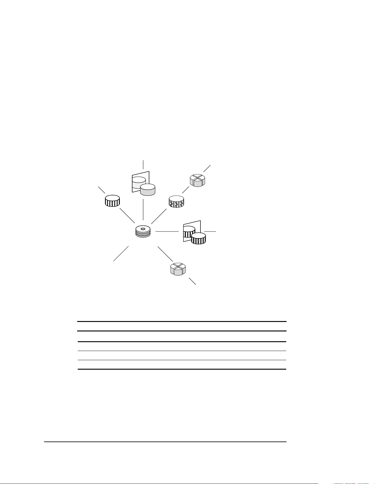
3–3
Unit
Unit
Stripeset
Mirrorset
RAIDset
Disk drives
Unit
Figure 3–1. Units Created from Storagesets, Partitions, and Drives
Partitioned
disk drive
Unit
Partitioned
storageset
Striped
mirrorset
Unit
CXO5368B
Table 3–1 Controller Limitations for RAIDsets
Unit
RAIDset Type Limit
Total number of RAID5 20
Total number of RAID5 + RAID1 30
Total number of RAID5 + RAID1 + RAID0 45
Compaq HSZ80 Array Controller ACS Version 8.3 Configuration and CLI Reference Guide
Page 94

3–4 Creating Storagesets
Planning and Configuring Storagesets
Use this procedure to plan and configure the storagesets for your subsystem. Use the
references in each step to locate details about specific commands and concepts.
1. Create a storageset and device profile. See “Creating a Storageset and Device
Profile,” page 3–5 for suggestions about creating a profile.
2. Determine your storage r equirement s. Use the ques tions in “Determining S torage
Requirements,” page 3–7 to help you.
3. Choose the type of s toragesets yo u need to u se in your s ubsystem. S ee “Choosin g
a Storageset Type,” page 3–8 for a comparison and description of each type of
storageset.
4. Select names for your storagesets and units. See “Creating a Storageset Map,”
page 3–34 for details about selecting names.
5. Assign unit numbers to storagesets so the host can access the units. See “Node
IDs,” page 3–30 for informat ion about how to assig n un it numbers to storagesets.
6. Create a storageset map to help you configure your subsystem. See “Creating a
Storageset Map,” page 3–34 for suggestions about creating a storageset map.
7. If you are going to partition your storagesets, plan the partitions. See “Planning
Partitions,” page 3–40 for information about p a rti tions and how to plan for them.
8. Choose the switches that you will want to set for your storagesets and devices.
See“Choosing Switches for Storagesets and Devices,” page 3–42 for a
description of the switches you can select for storagesets.
9. Configure the storagesets you have planned using one of these methods:
❏ Use StorageWorks Command Console (SWCC) to set up and manage RAID
storage subsystems. See the SWCC Getting Started Gui d e for d etails about using
SWCC to configure your storagesets.
❏ Use CLI commands. This me thod al lo ws you fl ex ib ility in def in ing an d nam-
ing storagesets. See “Configuring Storagesets,” page 4–1 for information about
configuring each type of storageset using CLI commands.
Page 95

Creating a Storageset and Device Profile
Creating a profile for your storagesets and device s can help simplify the configuration
process. This chapter helps you to choose the storagesets that best suit your n eeds and
helps you to make informed decision s about the switches that you can enable for each
storageset or storage device that you configure in your subsystem.
Familiarize yourself with the kinds of information contained in a storageset profile, as
shown in Figure 3–3.
Appendix contains blank profiles that you can copy and use to record the details for
your storagesets. Use the information in this chapter to help you make decisions when
creating storageset profiles.
3–5
Compaq HSZ80 Array Controller ACS Version 8.3 Configuration and CLI Reference Guide
Page 96

3–6 Creating Storagesets
Type of Storageset
___ Mirrorset
Storageset Name.........
Disk Drives...................
Unit Number.................
✔ RAIDset ___ Stripeset ___ Striped Mirrorset
accept default values
DISK10300, DISK20300, DISK30300
accept default
Partitions
Unit # Unit # Unit # Unit # Unit # Unit # Unit # Unit #
%%%%%%%%
RAIDset Switches
Reconstruction Policy Reduced Membership Replacement Policy
Normal (default)
✔
Fast
____
✔ No (default)
Yes, missing:
____
✔ Best performance
(default)
Best fit
____
None
____
Mirrorset Switches
Replacement Policy Copy Policy Read Source
___ Best performance (default)
Best fit
___
None
___
Normal (default)
___
Fast
___
___
Least busy (default)
Round robin
___
Disk drive:
___
Initialize Switches
Chunk size Save Configuration Metadata
Automatic (default)
✔
64 blocks
____
128 blocks
____
____
256 blocks
Other:
____
____ No (default)
✔ Yes
✔ Destroy (default)
Retain
____
Unit Switches
Read Cache Read-Ahead Cache Maximum Cache Transfer Error Mode*
✔
____
Yes (default)
No
✔ Yes (default)
No
____
✔ 32 blocks (default)
Other:
____
Write Cache Write Protection Availability
____ Yes (default)
✔ No
✔ No (default)
____
Yes
✔ Run (default)
____
NoRun
___
Normal
Failsafe
___
*Valid only for
mirrorsets with DT
support enabled
Figure 3–2. Storageset Profile
Page 97

Determining Storage Requirements
Start the planning process by determining your storage requirements. Here are a few
of the questions you should ask yourself:
■ What applications or user groups will access the subsystem? How much capacity
do they need?
■ What are the I/O requirements? If an application is data-transfer intensive, what
is the required transfer rate? If it is I/O-request intensive, what is the required
response time? What is the read/write ratio for a typical request?
■ Are most I/O requests directed to a small percentage of the disk drives? Do you
want to keep it that way or balance the I/O load?
■ Do you store mission-critical data? Is availability the highest priority or would
standard backup procedures suffice?
Use your responses to these questions along with Table 3 –2 to determine the types of
storagesets you should create to satisfy your organization’s requirements.
3–7
Compaq HSZ80 Array Controller ACS Version 8.3 Configuration and CLI Reference Guide
Page 98

3–8 Creating Storagesets
Choosing a Storageset Type
Different applications may have different storage requirements, so you will probably
want to configure more than one kind of storageset in your subsystem.
All of the storagesets described in this book implement RAID technology.
Consequently, they all share one important feature: each storageset, whether it
contains two disk drives or ten, looks like one large, virtual disk drive to the host.
Table 3–2 compares different kinds of storagesets to help you determine which ones
satisfy your requirements.
Table 3–2 A Comparison of Different Kinds of Storagesets
Storageset Type Relative
Availability
Array of disk
drives (JBOD)
Stripeset
(RAID 0)
Mirrorset
(RAID1)
RAIDset
(RAID 3/5)
Striped Mirrorset
(RAID 0+1)
Equivalent to a
single disk drive
Proportionate to
number of disk
drives; worse than
single disk drive
Excellent Good/Fair Good/Fair System drives; critical
Excellent Excellent/Fair Good/Poor High request rates,
Excellent Excellent if used
Request Rate
(Read/Write) I/O per
Identical to single
disk drive
Excellent if used
with large chunk
size
with large chunk
size
second
Transfer Rate (Read/
Write) MB per
second
Identical to single
disk drive
Excellent if used
with small chunk
size
Excellent if used
with small chunk
size
Applications
High performance for
noncritical data
files
read-intensive, data
lookup
Any critical responsetime application
For a comprehensive discussion of RAID, refer to The RAIDBOOK—A Source Book
for Disk Array Technology.
Page 99

Using Stripesets to Increase I/O Performance
Stripesets enhance I/O performance by spreading the data across multiple disk dri ves.
Large I/O requests are broken into small segments called “chunks.” These chunks are
then “striped” across the disk drives in the storageset, thereby allowing several disk
drives to participate in one large I/O request or handle several I/O requests
simultaneously.
For example, in a three-member stripeset that contains disk drives 10000, 20000, and
30000, the first chunk of an I/O request is written to 10000, the second to 20000, the
third to 30000, the fourth to 10000, and so forth until all of the d a ta has been written
to the drives.
3–9
6
Chunk 1
1
2
3
0
0
1
0
k
0
s
i
D
4
0
2
0
k
0
s
0
i
D
2
5
5
4
0
3
0
k
0
s
i
D
36
0
CXO5507A
Figure 3–3. Striping Lets Several Disk Drives Participate in Each I/O Request
The relationship between the chunk size and the average request size determines if
striping maximizes the request rate or the data-transfer rate. You can set the chunk
size or let the controller set it automatically. See “Chunk Size,” page 3–51, for
information about setting the chunk size.
Compaq HSZ80 Array Controller ACS Version 8.3 Configuration and CLI Reference Guide
Page 100

3–10 Creating Storagesets
A major benefit of striping is that it balances the I/O load across all of the disk drives
in the storageset. This can increase the subsystem’s performance by eliminating the
hot spots, or high localities of reference, that occur when frequently accessed data
becomes concentrated on a single disk drive.
Considerations for Planning a Stripeset
Keep the following points in mind as you plan your stripesets:
■ A controller can support up to 45 storagesets, consisting of stripesets, mirrorsets
and RAIDsets (see Table 3–1).
■ Reporting methods and size li mitations prevent certain operating systems from
working with large stripesets. See the HSZ80 Array Controller ACS Version 8.3
Release Notes or the Quick Setup Guide that came with your software platform
kit for details about these restrictions .
■ A storageset should only contain disk drives of the same capacity. The controller
limits the capacity of each member to the capacity of the smallest member in the
storageset when the storagest is initialized (the base member size). Thus, if you
combine 9 GB disk driv es with 4 GB disk dri v es in the same storageset, the 4 GB
disk drive will be the base member size and you will waste 5 GB of capacity on
each 9 GB member.
If you need high performance and high availability, consider using a RAIDset,
striped mirrorset, or a host-based shadow of a stripeset.
NOTE: A striped mirrorset cannot be created if the mirrorsets are enabled for
DT_SUPPORT.
■ Striping does not protect against data loss. In fact, because the failure of one
member is equivalent to the failure of the entire stripeset, the likelihood of losing
data is higher for a stripeset than for a single disk drive.
For example, if the mean time between failures (MTBF) for a single disk is one
hour, then the MTBF for a stripeset that com pri ses N such disks is l/N hours. As
another example, if a single disk’s MTBF is 150,000 hours (about 17 years), a
stripeset comprising four of these disks wo uld only have an MTBF of slightly
more than four years.
 Loading...