

Page 1

Compaq Presario CQ42 Notebook
PC and HP G42 Notebook PC
Maintenance and Service Guide
SUMMARY
This guide is a troubleshooting reference used for maintaining and servicing the computer. It provides
comprehensive information on identifying computer features, components, and spare parts;
troubleshooting computer problems; and performing computer disassembly procedures.
Page 2

© Copyright 2010 Hewlett-Packard
Development Company, L.P.
Bluetooth is a trademark owned by its
proprietor and used by Hewlett-Packard
Company under license. Intel and
Arrandale are trademarks of Intel
Corporation in the United States and other
countries. Microsoft and Windows are U.S.
registered trademarks of Microsoft
Corporation. SD Logo is a trademark of its
proprietor.
The information contained herein is subject
to change without notice. The only
warranties for HP products and services are
set forth in the express warranty statements
accompanying such products and services.
Nothing herein should be construed as
constituting an additional warranty. HP shall
not be liable for technical or editorial errors
or omissions contained herein.
First Edition: March 2010
Document Part Number: 594158-001
Page 3

MSG revision history
Revision Publication date Description
A March 2010 Edited this guide to include HP G42 Notebook PC and Compaq CQ42
Notebook PC information only.
B October 2010
C December 2010 ● Added newly supported hard drives to spare parts listings in the
Added newly supported hard drives to spare parts listings in the
●
following locations:
Mass storage devices on page 34, Sequential part number
listing on page 37, Hard drive on page 53.
Added newly supported memory modules to spare parts listings
●
in the following locations:
on page 24, Mass storage devices on page 34, Sequential part
number listing on page 37, Memory module on page 61.
● Added newly supported processors to spare parts listings in the
following locations: Computer major components on page 24,
Mass storage devices on page 34, Sequential part number
listing on page 37, Processor on page 94.
● Added newly supported system boards to spare parts listings in
the following locations: Computer major components
on page 24, Mass storage devices on page 34, Sequential part
number listing on page 37, System board on page 83.
following locations:
Hard drive on page 53.
● Added newly supported processors to spare parts listings in the
following locations: Computer major components on page 24,
Mass storage devices on page 34, Sequential part number
listing on page 37, Processor on page 94.
Added newly supported system boards to spare parts listings in
●
the following locations: Computer major components
on page 24, Mass storage devices on page 34, Sequential part
number listing on page 37, System board on page 83.
Computer major components on page 24,
Computer major components
Computer major components on page 24
Added newly supported wireless devices to spare parts listing in
●
the following locations:
on page 24, Sequential part number listing on page 37,
Component replacement procedures on page 50, WLAN
Module.
Computer major components
ENWW iii
Page 4

iv MSG revision history ENWW
Page 5

Safety warning notice
WARNING! To reduce the possibility of heat-related injuries or of overheating the computer, do not
place the computer directly on your lap or obstruct the computer air vents. Use the computer only on
a hard, flat surface. Do not allow another hard surface, such as an adjoining optional printer, or a soft
surface, such as pillows or rugs or clothing, to block airflow. Also, do not allow the AC adapter to
contact the skin or a soft surface, such as pillows or rugs or clothing, during operation. The computer
and the AC adapter comply with the user-accessible surface temperature limits defined by the
International Standard for Safety of Information Technology Equipment (IEC 60950).
ENWW v
Page 6

vi Safety warning notice ENWW
Page 7

Table of contents
1 Product description ........................................................................................................................................ 1
2 External component identification .............................................................................................................. 11
Identifying the hardware ..................................................................................................................... 11
Top components ................................................................................................................................. 12
TouchPad .......................................................................................................................... 12
Lights ................................................................................................................................. 13
Button and speakers .......................................................................................................... 14
Keys ................................................................................................................................... 15
Display ............................................................................................................................... 16
Right-side components ....................................................................................................................... 17
Left-side components ......................................................................................................................... 18
Bottom components ........................................................................................................................... 19
Wireless antennas .............................................................................................................................. 20
Additional hardware components ....................................................................................................... 21
3 Illustrated parts catalog ............................................................................................................................... 23
Serial number location ........................................................................................................................ 23
Computer major components ............................................................................................................. 24
Display assembly components ........................................................................................................... 31
Plastics Kit .......................................................................................................................................... 33
Mass storage devices ......................................................................................................................... 34
Miscellaneous parts ............................................................................................................................ 36
Sequential part number listing ............................................................................................................ 37
4 Removal and replacement procedures ....................................................................................................... 45
Preliminary replacement requirements ............................................................................................... 45
Tools required .................................................................................................................... 45
Service considerations ....................................................................................................... 45
Plastic parts ....................................................................................................... 45
Cables and connectors ..................................................................................... 46
Drive handling ................................................................................................... 46
Grounding guidelines ......................................................................................................... 47
ENWW vii
Page 8

Electrostatic discharge damage ........................................................................ 47
Packaging and transporting guidelines ............................................. 48
Workstation guidelines ..................................................................... 48
Equipment guidelines ....................................................................... 49
Component replacement procedures ................................................................................................. 50
Serial number .................................................................................................................... 50
Computer feet .................................................................................................................... 51
Battery ............................................................................................................................... 52
Hard drive .......................................................................................................................... 53
Optical drive ....................................................................................................................... 56
WLAN module .................................................................................................................... 58
Memory module ................................................................................................................. 61
Keyboard ........................................................................................................................... 63
Top cover ........................................................................................................................... 65
Speaker assembly ............................................................................................................. 68
Power button board ........................................................................................................... 69
TouchPad button board ..................................................................................................... 70
Modem module .................................................................................................................. 71
Bluetooth module ............................................................................................................... 73
USB board ......................................................................................................................... 74
Power connector cable ...................................................................................................... 75
Display assembly ............................................................................................................... 76
System board ..................................................................................................................... 83
Optical drive SATA cable and connector ........................................................................... 87
RTC battery ....................................................................................................................... 89
Fan/heat sink assembly ..................................................................................................... 91
Processor ........................................................................................................................... 94
5 Setup Utility ................................................................................................................................................... 97
Computer Setup in Windows 7 ........................................................................................................... 97
Starting Setup Utility .......................................................................................................... 97
Using Setup Utility ............................................................................................................. 97
Changing the language of Setup Utility ............................................................. 97
Navigating and selecting in Setup Utility ........................................................... 98
Displaying system information .......................................................................... 98
Restoring default settings in Setup Utility .......................................................... 99
Exiting Setup Utility ......................................................................................... 100
Setup Utility menus .......................................................................................................... 100
Main menu ...................................................................................................... 100
Security menu ................................................................................................. 100
System Configuration menu ............................................................................ 101
Diagnostics menu ............................................................................................ 101
Computer Setup in Linux .................................................................................................................. 102
viii ENWW
Page 9

Starting Computer Setup ................................................................................................. 102
Using Computer Setup .................................................................................................... 102
Navigating and selecting in Computer Setup .................................................. 102
Restoring factory settings in Computer Setup ................................................. 103
Computer Setup menus ................................................................................................... 104
File menu ........................................................................................................ 104
Security menu ................................................................................................. 105
Diagnostics menu ............................................................................................ 105
System Configuration menu ............................................................................ 106
6 Specifications .............................................................................................................................................. 109
Computer specifications ................................................................................................................... 109
35.6-cm (14.0-in) display specifications ........................................................................................... 110
Hard drive specifications .................................................................................................................. 111
DVD±RW SuperMulti Double-Layer Drive with LightScribe specifications ....................................... 112
Blu-ray ROM with LightScribe DVD±R/RW SuperMulti DL Drive specifications .............................. 113
System resource specifications ........................................................................................................ 114
7 Backup and recovery .................................................................................................................................. 115
Windows 7 ........................................................................................................................................ 115
Creating recovery discs ................................................................................................... 116
Backing up your information ............................................................................................ 117
Using Windows Backup and Restore .............................................................. 118
Using system restore points ............................................................................ 119
When to create restore points ........................................................ 119
Create a system restore point ........................................................ 119
Restore to a previous date and time ............................................... 119
Performing a recovery ..................................................................................................... 119
Recovering from the recovery discs ................................................................ 120
Recovering from the dedicated recovery partition (select models only) .......... 120
Linux backup and recovery .............................................................................................................. 121
8 Connector pin assignments ....................................................................................................................... 123
Audio-out (headphone) ..................................................................................................................... 123
Audio-in (microphone) ...................................................................................................................... 123
External monitor ............................................................................................................................... 124
RJ-11 (modem) ................................................................................................................................ 125
RJ-45 (network) ................................................................................................................................ 125
HDMI ................................................................................................................................................ 126
Universal Serial Bus ......................................................................................................................... 127
9 Power cord set requirements .................................................................................................................... 129
Requirements for all countries or regions ......................................................................................... 129
ENWW ix
Page 10

Requirements for specific countries or regions ................................................................................ 130
10 Recycling ................................................................................................................................................... 131
Battery .............................................................................................................................................. 131
Display .............................................................................................................................................. 131
Index ................................................................................................................................................................. 137
x ENWW
Page 11

1 Product description
Category Description HP G42 HP G42 Compaq
Discrete UMA Discrete UMA Models
Product
Name
HP G42 Notebook
Processors Intel® Arrandale™
i7-620M, 2.66-GHz,
i5-540M, 2.53-GHz,
i5-520M, 2.4-GHz,
i5-430M 2.26-GHz
Compaq Presario
CQ42 Notebook PC
PC
SC turbo, 4-MB L3
cache
SC turbo, 3-MB L3
cache
SC turbo, 3-MB L3
cache
(turbo to 2.53- GHz)
3-MB L3 cache
√√√
√√
√√√√
√√√√
√√√√
√√√√
Presario
CQ42
Compaq
Presario
CQ42
150-199
Compaq
Presario
CQ42
UMA Models
100-149
i3-350M, 2.26-GHz
3-MB L3 cache
i3-330M, 2.13-GHz
3-MB L3 cache
i3-390M processor
2.66-GHz 3MB 35W
i5-480M processor
2.66-GHz 3MB 35W
P6300 - 2.26-GHz
3M
i5-480M processor
2.66-GHz 3MB 35W
Intel Pentium™
√√√√
√√√√
√√
√√
√√
√√
ENWW 1
Page 12

Category Description HP G42 HP G42 Compaq
Presario
CQ42
Compaq
Presario
CQ42
Compaq
Presario
CQ42
Discrete UMA Discrete UMA Models
150-199
DC T4300, 2.1-GHz,
800-MHz FSB, 1-MB
L2 cache
DC T4400, 2.2-GHz,
800-MHz FSB, 1-MB
L2 cache
Intel Celeron™
DC T3000, 1.8-GHz
800-MHz FSB, 1-MB
L2 cache
DC T3100, 1.9-GHz,
800-MHz FSB, 1-MB
L2 cache
Mobile 925 - 2.3-
GHz 1M L2 cache
Chipset Intel® HM55
Express
Intel® GL40 √
Southbridge: ICH9m √
√
√
√
√
√√ √
√√√√
UMA Models
100-149
Graphics Intel UMA
(integrated)/HD
Graphics with
shared video
memory (memory
size is dynamic
change):
Up to 251 MB
●
on computers
with 1024 MB
of system
memory
Up to 358 MB
●
on computers
with more than
2048 MB of
system
memory
√ √
2 Chapter 1 Product description ENWW
Page 13

Category Description HP G42 HP G42 Compaq
Presario
CQ42
Compaq
Presario
CQ42
Compaq
Presario
CQ42
Intel UMA
(integrated)/GMA
4500M - GL40
chipset with shared
video memory
(memory size is
dynamic change):
● Up to 1759 MB
for computers
with more than
4096 MB of
system
memory (64 bit)
● Up to 1309 MB
for computers
with more than
4096 MB of
system
memory (32 bit)
Up to 1309 MB
●
for computers
with more than
3072 MB of
system
memory
Discrete UMA Discrete UMA Models
150-199
√
UMA Models
100-149
Up to 797 MB
●
for computers
with more than
2048 MB
system
memory
Up to 285 MB
●
for computers
with more than
1024 MB of
system
memory
ENWW 3
Page 14

Category Description HP G42 HP G42 Compaq
Presario
CQ42
Compaq
Presario
CQ42
Compaq
Presario
CQ42
ATi Discrete PCI
Express x 16
Graphics
● ATi Mobility
Radeon ParkLP S3 package
(ATI Mobility
Radeon™
HD5430 with
512-MB of
dedicated video
memory (64MB×16 DDR3,
4 pcs, 800MHz))
Switchable
Discrete Graphics
● ATi Robson XT
(ATI Mobility
Radeon™
HD6370) with
512MB of
dedicated
memory
(64Mx16 DDR3
800 MHz x 4
PCs)
Discrete UMA Discrete UMA Models
150-199
√
√ √
UMA Models
100-149
ATi Robson XT
●
(ATI Mobility
Radeon™
HD6370) with
1GB of
dedicated
memory
(128Mx16
DDR3 800 MHz
x 4 PCs)
Support for BD or
HD-DVD playback
with HD decoder
and DX10 support
Panel 35.6-cm (14.0-in)
HD LED BrightView
(1366 x 768)
16:9 wide aspect
ratio
Memory 2 SODIMM slots √√√√√
√√√√√
√√√√√
√√√√√
4 Chapter 1 Product description ENWW
Page 15

Category Description HP G42 HP G42 Compaq
Presario
CQ42
Compaq
Presario
CQ42
Compaq
Presario
CQ42
Customer-
accessible and
upgradable
Supports up to 8 GB
of system memory
DDR3, 1066-MHz,
dual-channel
memory (DDR3
1333 MHz can be
downgraded to
DDR3 1066 MHz)
DDR3, 800-MHz,
dual-channel
memory (DDR3
1333 MHz can be
downgraded to
DDR3 800 MHz)
Supports the
following
configurations:
● 4096 MB (2048
MB × 2)
Discrete UMA Discrete UMA Models
150-199
√√√√√
√√√√√
√√√√
√
√√√√√
UMA Models
100-149
● 3072 MB (1024
Hard drives Supports 9.5-mm,
Serial ATA √√√√√
Supports the
MB × 1 + 2048
MB × 1)
2048 MB (2048
●
MB × 1)
2048 MB (1024
●
MB × 2)
1024 MB (1024
●
MB × 1)
6.35-cm (2.5-in)
hard drive
following drives:
750 GB, 5400
●
rpm
640 GB, 5400
●
rpm
500 GB, 7200
●
rpm
√√√√√
√√√√√
√√√√√
√√√√√
√√√√√
√√√√
√√√√
√√√√
ENWW 5
Page 16

Category Description HP G42 HP G42 Compaq
Presario
CQ42
Compaq
Presario
CQ42
Compaq
Presario
CQ42
Discrete UMA Discrete UMA Models
150-199
● 320 GB, 7200
● 250 GB, 7200
● 160 GB, 7200
Optical
drives
SATA √√√√√
12.7-mm (0.50-in)
Supports the
● Blu-ray ROM
rpm
rpm
rpm
Fixed (removal of
one screw required)
fixed tray load
following drives:
Blu-ray ROM
●
with
LightScribe
DVD±R/RW
SuperMulti DL
Drive
DVD±R/RW
SuperMulti DL
Drive
√√√√√
√√√√√
√√√√
√√√√√
√√√√√
√√√√
√√√√
UMA Models
100-149
● DVD±R/RW
Diskette drive Supports external
Camera VGA camera √√√√√
Fixed (no tilt) √√√√√
640 × 480 by 24
Microphone One microphone,
Audio HD audio √√√√√
Supports Microsoft
DVD±R/RW
●
SuperMulti DL
Drive with
LightScribe
SuperMulti DL
Drive
USB drive only
frames per second
analog
Premium
requirements
√√√√√
√√√√√
√√√√√
√√√√√
√√√√√
√√√√√
6 Chapter 1 Product description ENWW
Page 17

Category Description HP G42 HP G42 Compaq
Presario
CQ42
Compaq
Presario
CQ42
Compaq
Presario
CQ42
Altec Lansing
Modem
(select models
only)
Ethernet Integrated 10/100
Wireless Integrated wireless
Intel Centrino
Intel Centrino
speakers
Support for optional
high-speed 56k
modem
network interface
card (NIC)
local area network
(WLAN) options by
way of wireless
module:
Wireless-N 1000
802.11b/g 1x2
Wireless-N 1000
802.11b/g 1x2 plus
Broadcom 2070
Bluetooth 2.1+EDR
Adapter
Discrete UMA Discrete UMA Models
150-199
√√√√√
√√√√√
√√√√√
√√√√
√√√√
UMA Models
100-149
Atheros AR9285
802.11b/g/n 1x1
WiFi Adapter
Atheros AR9285
802.11b/g/n 1x1
WiFi Adapter plus
Broadcom 2070
Bluetooth 2.1+EDR
Adapter
Broadcom 4312G
802.11b/g WiFi
Adapter
Broadcom 4312G
802.11b/g WiFi
Adapter plus
Broadcom 2070
Bluetooth 2.1+EDR
Adapter
Realtek RTL8191SE
802.11b/g/n 1x1
WiFi Adapter
√√√√√
√√√√√
√
√
√√√√√
ENWW 7
Page 18

Category Description HP G42 HP G42 Compaq
Presario
CQ42
Compaq
Presario
CQ42
Compaq
Presario
CQ42
Realtek RTL8191SE
External
media card
(select models
only )
Single port
Supports mini
Ports VGA (Dsub 15-pin)
802.11b/g/n 1x1
WiFi Adapter plus
Broadcom 2070
Bluetooth 2.1+EDR
Adapter
5-in-1 Digital Media
Slot; supports SD,
MMC, MS, Mspro,
xD
configured as either
HDMI or 5-in-1
Digital Media Slot
versions of SD,
MMC, and MS Duo
with adapter
(adapter not
included)
supporting 1600 x
1200 resolution at
75 Hz; disabled
when connected to
devices through
Expansion port 3
Discrete UMA Discrete UMA Models
150-199
√√√√√
√√√√√
√√√√
√√√√√
√√√√√
UMA Models
100-149
Hot plug/unplug and
auto detect for wideaspect or standardaspect video
HDMI v1.3
supporting 1080p
with HDCP key
Single port
configured for either
HDMI or 5-in-1 card
reader
USB 2.0 (3) √√√√√
RJ-11 (modem) with
modem option
RJ-45 (Ethernet,
with link and activity
lights)
Audio-in (mono
microphone)
Audio-out (stereo
headphone)
√√√√√
√√√√√
√√√√√
√√√√√
√√√√√
√√√√√
√√√√√
8 Chapter 1 Product description ENWW
Page 19

Category Description HP G42 HP G42 Compaq
Presario
CQ42
Compaq
Presario
CQ42
Compaq
Presario
CQ42
Discrete UMA Discrete UMA Models
150-199
Smart-pin AC
Keyboard/
pointing
devices
TouchPad with 2
Power
requirements
65-W AC adapter
90-W AC adapter
Security Security cable slot √√√√√
Operating
system
adapter plug
14.0-inch keyboard √√√√√
buttons and 2-way
scroll (taps enabled
as default)
6-cell (47-Wh) 2.20Ah Li-ion battery
with Smart-Pin DC
connector
with Smart-Pin DC
connector
Preinstalled:
√√√√√
√√√√√
√√√√√
√√ √√
√
UMA Models
100-149
Windows 7
Professional (32 &
64 bit)
Windows 7 Home
Premium (32 & 64
bit)
Windows 7 Home
Basic (32 & 64 bit)
Free DOS √√√√√
Serviceability End-user
replaceable parts:
AC adapter √√√√√
Battery (system) √√√√√
Hard drive √√√√√
Memory module √√√√√
Optical drive √√√√√
Mini-card device √√√√√
√√√√
√√√√√
√√√√√
ENWW 9
Page 20

10 Chapter 1 Product description ENWW
Page 21

2 External component identification
Identifying the hardware
Components included with the computer may vary by region and model. The illustrations in this
chapter identify the standard features on most computer models.
To see a list of hardware installed in the computer, follow these steps:
1. Select Start > My Computer.
2. In the left pane of the System Tasks window, select View system information.
3. Select Hardware tab > Device Manager.
You can also add hardware or modify computer configurations using Device Manager.
ENWW Identifying the hardware 11
Page 22
Top components
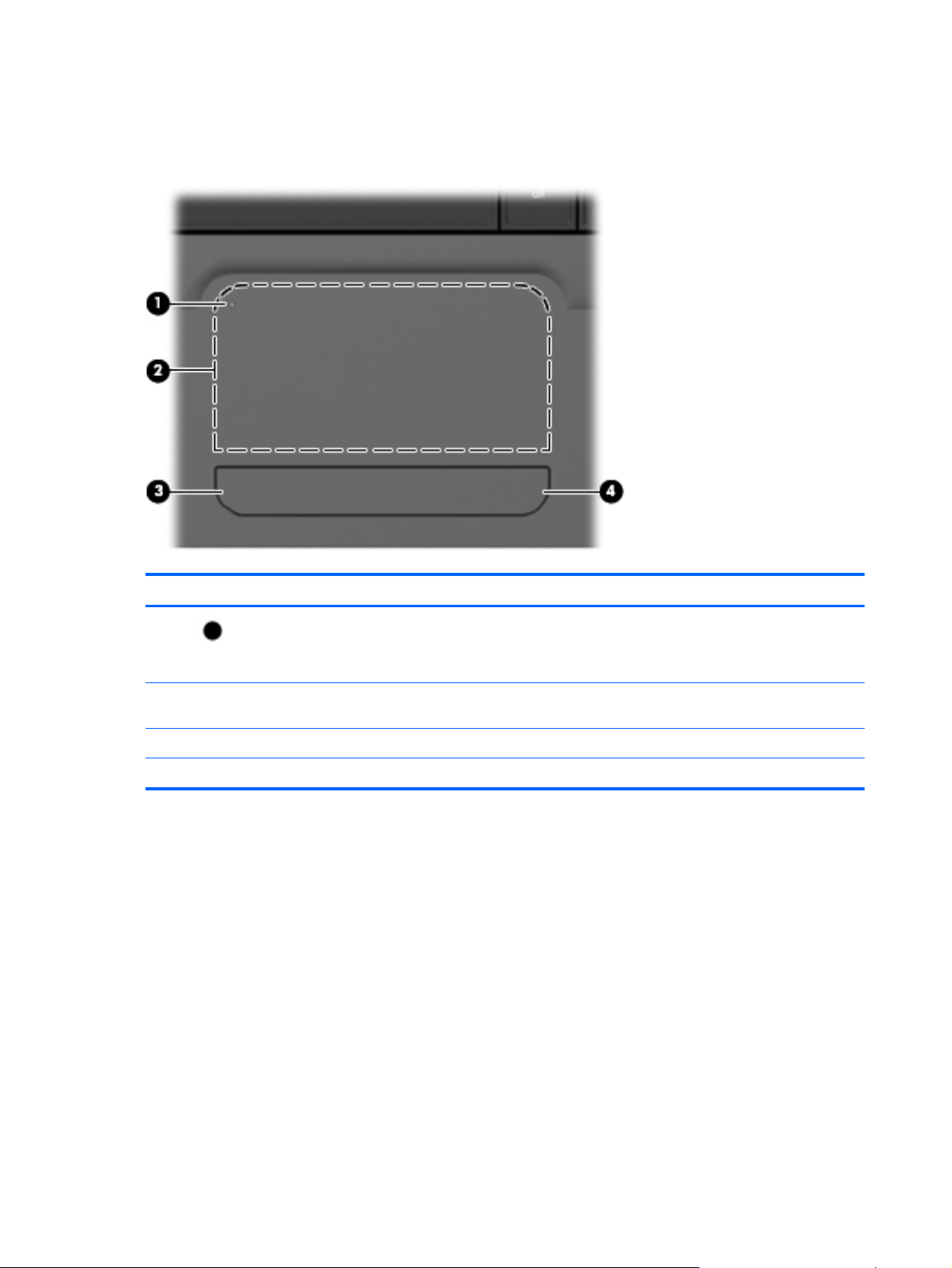
TouchPad
Component Description
(1)
(2) TouchPad zone Moves the pointer and selects or activates items on the
(3) Left TouchPad button Functions like the left button on an external mouse.
(4) Right TouchPad button Functions like the right button on an external mouse.
TouchPad off indicator To switch the TouchPad zone on and off, quickly double-tap
the TouchPad off indicator.
NOTE: When the TouchPad zone is active, the light is off.
screen.
There is an unmarked scroll zone inside the right edge of the TouchPad. To scroll up and down using
the TouchPad vertical scroll zone, slide your finger up or down inside the right edge of the TouchPad.
For more information about TouchPad features, refer to” Using the TouchPad” section later in this
guide.
12 Chapter 2 External component identification ENWW
Page 23
Lights
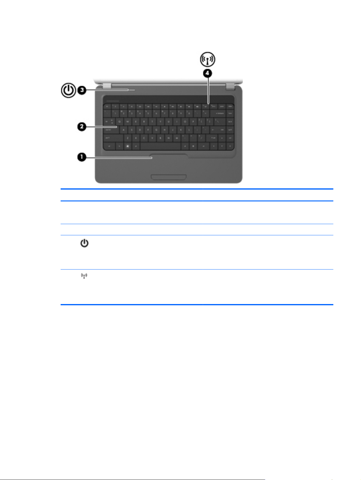
Component Description
(1) TouchPad light
(2) Caps lock light On: Caps lock is on.
(3)
(4)
Power light
Wireless light
On: The TouchPad is disabled.
●
● Off: The TouchPad is enabled.
On: The computer is on.
●
● Blinking: The computer is in the Sleep state.
● Off: The computer is off or in Hibernation.
White: An integrated wireless device, such as a
●
wireless local area network (WLAN) device and/or a
Bluetooth® device, is on.
Amber: All wireless devices are off.
●
ENWW Top components 13
Page 24
Button and speakers
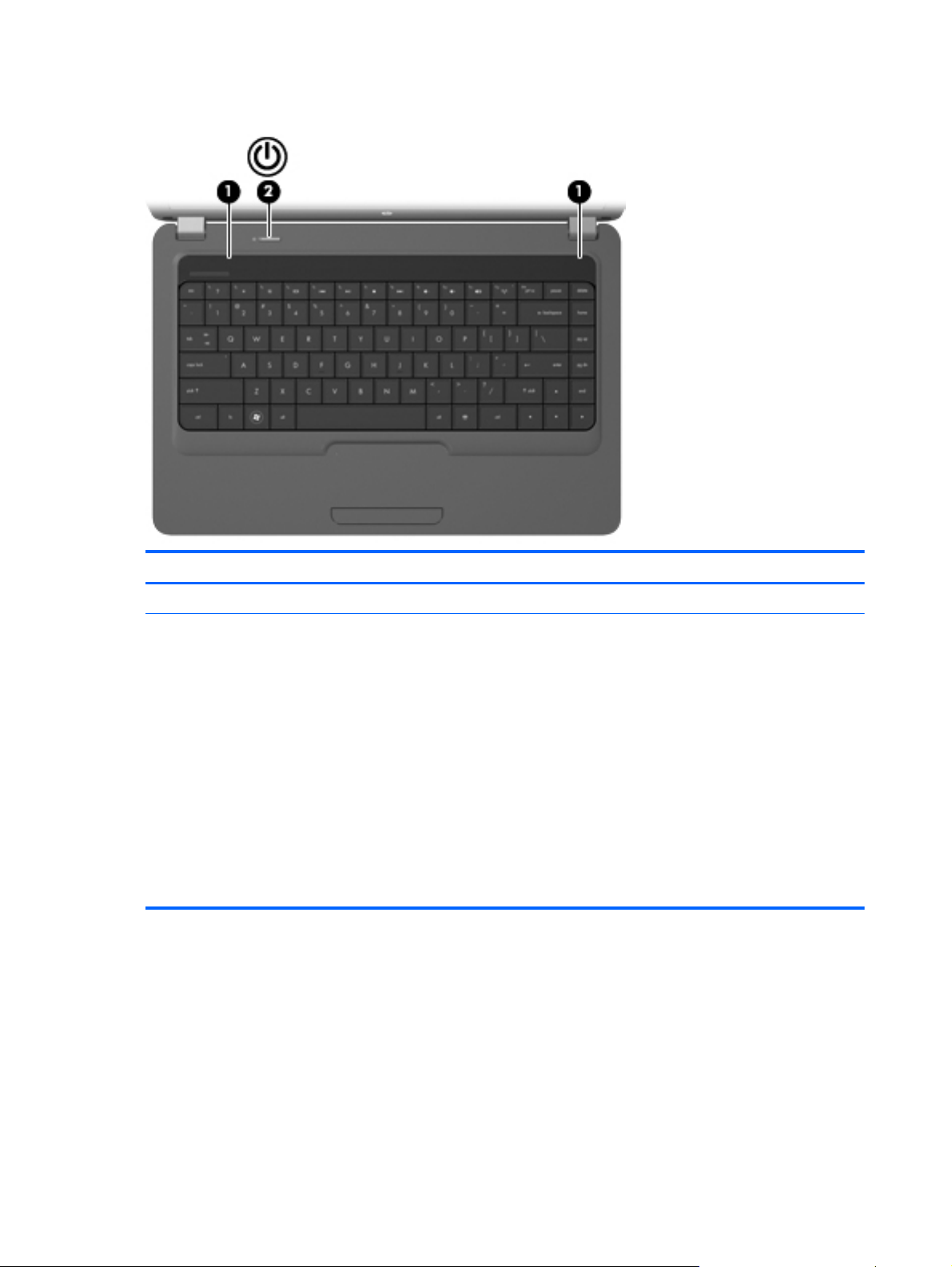
Component Description
(1) Speakers (2) Produce sound.
(2) Power button
When the computer is off, press the button to turn on the
●
computer.
● When the computer is on, press the button briefly to
initiate Sleep.
When the computer is in the Sleep state, briefly press
●
the button to exit Sleep.
When the computer is in Hibernation, briefly press the
●
button to exit Hibernation.
If the computer has stopped responding and Windows®
shutdown procedures are ineffective, press and hold the
power button for at least 5 seconds to turn off the computer.
To learn more about your power settings, select Start >
Control Panel > System and Security > Power Options.
14 Chapter 2 External component identification ENWW
Page 25
Keys
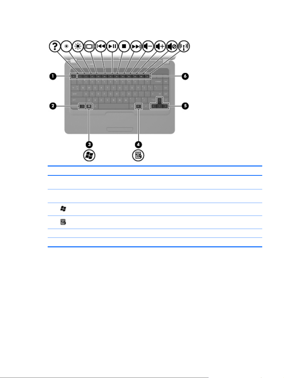
Component Description
(1) esc key Displays system information when pressed in combination with
(2) fn key Displays system information when pressed in combination with
(3)
(4)
(5) Navigation keys Navigate using the Up, Down, Left and Right arrow keys.
(6) Action keys Execute frequently used system actions.
Windows logo key Displays the Windows Start menu.
Windows applications key Displays a shortcut menu for items beneath the pointer.
the fn key.
the esc key.
ENWW Top components 15
Page 26
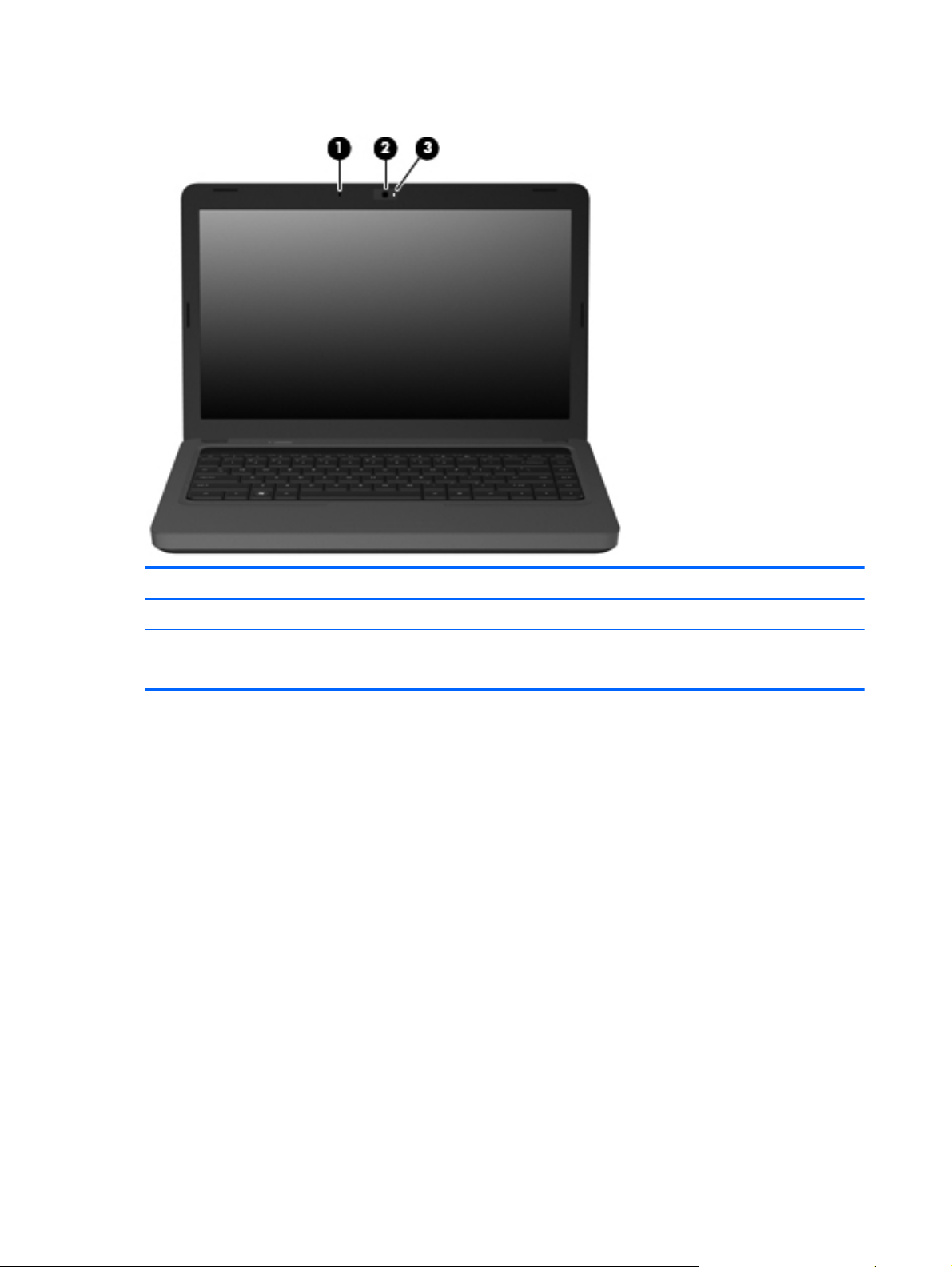
Display
Component Description
(1) Internal microphone Records sound.
(2) Integrated webcam (select models only) Records audio and video and captures still photographs.
(3) Integrated webcam light (select models only) On: The integrated webcam is in use.
16 Chapter 2 External component identification ENWW
Page 27
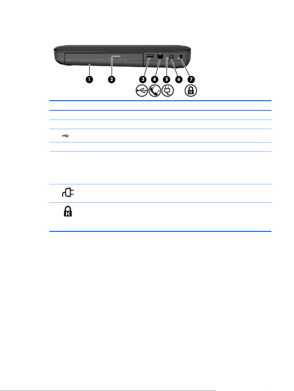
Right-side components
Component Description
(1) Optical drive Reads and writes to optical discs.
(2) Optical drive light Blinking: The optical drive is being accessed.
(3)
(4) RJ-11 (modem) jack (select models only) Connects a modem cable.
(5) AC adapter/power/battery light
(6)
(7)
USB port Connects an optional USB device.
White: The computer is connected to external power and
●
the battery is fully charged.
● Blinking white: The computer is in the Sleep state.
Amber: A battery is charging.
●
Power connector Connects an AC adapter.
Security cable slot Attaches an optional security cable to the computer.
NOTE: The security cable is designed to act as a deterrent,
but it may not prevent the computer from being mishandled or
stolen.
ENWW Right-side components 17
Page 28
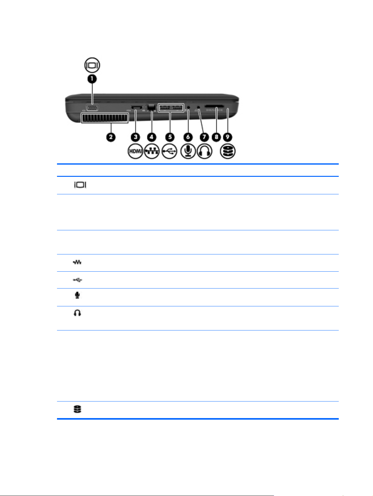
Left-side components
Component Description
(1)
(2) Vent Enables airflow to cool internal components.
(3) HDMI port (select models only) Connects an optional video or audio device, such as a high-
(4)
(5)
(6)
(7)
(8) Digital Media Slot (select models only) Supports the following optional digital card formats:
External monitor port Connects an external VGA monitor or projector.
NOTE: The computer fan starts up automatically to cool
internal components and prevent overheating. It is normal for
the internal fan to cycle on and off during routine operation.
definition television, or any compatible digital or audio
component.
RJ-45 (network) jack Connects a network cable.
USB ports (2) Connects optional USB devices.
Audio-in (microphone) jack Connects an optional computer headset microphone, stereo
array microphone, or monaural microphone.
Audio-out (headphone) jack Produces sound when connected to optional powered stereo
speakers, headphones, earbuds, a headset, or television
audio.
Memory Stick (MS)
●
Memory Stick Pro (MSP)
●
● MultiMediaCard (MMC)
● Secure Digital (SD) Memory Card
xD-Picture Card (XD)
●
(9)
Drive light On: The hard drive is in use.
18 Chapter 2 External component identification ENWW
Page 29
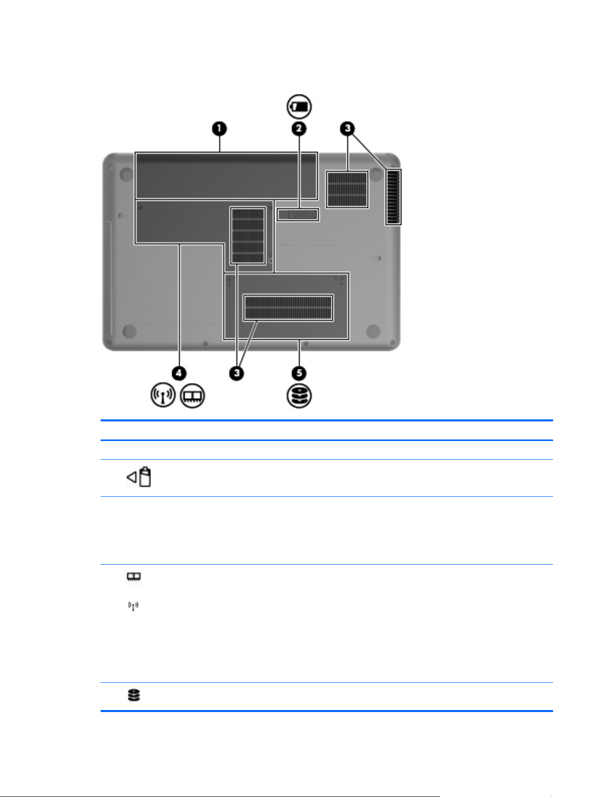
Bottom components
Component Description
(1) Battery bay Holds the battery.
(2)
(3) Vents (4) Enable airflow to cool internal components.
(4)
(5)
Battery release latch Releases the battery from the battery bay.
NOTE: The computer fan starts up automatically to cool
internal components and prevent overheating. It is normal
for the internal fan to cycle on and off during routine
operation.
Memory module compartment Contains 2 memory module slots and, on select models,
the wireless LAN (WLAN) device.
CAUTION: To prevent an unresponsive system, replace
the wireless module only with a wireless module
authorized for use in the computer by the governmental
agency that regulates wireless devices in your country or
region. If you replace the module and then receive a
warning message, remove the module to restore computer
functionality, and then contact technical support through
Help and Support.
Hard drive bay Holds the hard drive.
ENWW Bottom components 19
Page 30
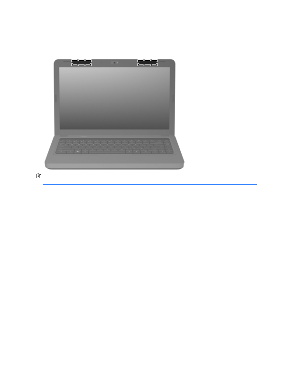
Wireless antennas
At least 2 antennas send and receive signals from one or more wireless devices. These antennas are
not visible from the outside of the computer.
NOTE: For optimal transmission, keep the areas immediately around the antennas free from
obstructions.
To see wireless regulatory notices, refer to the section of the Regulatory, Safety and Environmental
Notices that applies to your country or region. These notices are located in Help and Support.
20 Chapter 2 External component identification ENWW
Page 31
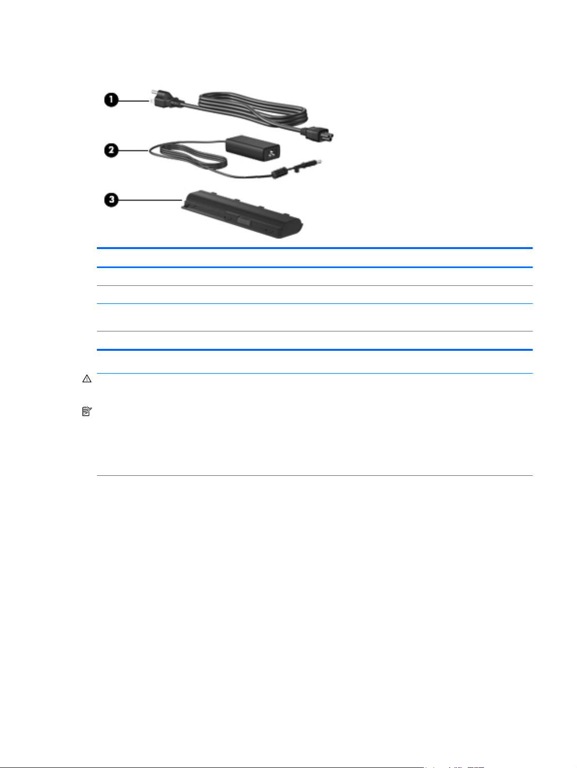
Additional hardware components
Component Description
(1) Power cord* Connects an AC adapter to an AC outlet.
(2) AC adapter Converts AC power to DC power.
(3) Battery* Powers the computer when the computer is not plugged into
external power.
*Power cords vary in appearance by country or region.
WARNING! Connecting the internal analog modem to a digital line can permanently damage the
modem. Immediately disconnect the modem cable if you accidentally connect it to a digital line.
NOTE: Telephone jacks vary by country or region. To use the modem and the modem cable
(included with select models only) outside the country or region in which you purchased the
computer, you must obtain a country- or region-specific modem cable adapter (included with select
models or purchased separately). The modem must be connected to an analog telephone line using a
6-pin, RJ-11 modem cable (included with select models only). Jacks for digital PBX systems may
resemble analog telephone jacks, but they are not compatible with the modem.
If the modem cable contains noise suppression circuitry, which prevents interference from TV and
radio reception, orient the circuitry end of the cable toward the computer.
ENWW Additional hardware components 21
Page 32

22 Chapter 2 External component identification ENWW
Page 33

3 Illustrated parts catalog
Serial number location
When ordering parts or requesting information, provide the computer serial number and model
number located in the battery bay of the computer.
ENWW Serial number location 23
Page 34

Computer major components
Item Description Spare part number
(1) 35.6 cm (14-in), WXGA, BrightView display assembly
NOTE: See
internal component spare part information.
For use with integrated microphone and webcam; Presario, matte black 592146-001
●
Display assembly components on page 31 for more display assembly
24 Chapter 3 Illustrated parts catalog ENWW
Page 35

Item Description Spare part number
● For use with integrated microphone and webcam; HP, silver (for models 1.1 and
● For use with integrated microphone and webcam; HP, white (for model 1.1 only) 606156-001
(2) Keyboards
● For use in Canada (English and French) 600175-121
For use with integrated microphone and webcam; Presario, biscotti 597617-001
●
For use with integrated microphone and webcam; HP, biscotti 600163-001
●
later)
For use with integrated microphone and webcam; HP, charcoal (for models 1.2 and
●
1.3 only)
For use with integrated microphone and webcam; HP, imperial blue (for models 1.2
●
and 1.3 only)
For use with integrated microphone and webcam; Presario, velvet red (for model
●
1.2 only)
For use with integrated microphone and webcam; HP, velvet red (for models 1.2
●
and 1.3 only)
For use in Brazil 600175-201
●
For use in Latin America 600175-161
●
For use in South Korea 600175-AD1
●
606155-001
622571-001
622572-001
624966-001
630907-001
● For use in Taiwan 600175-AB1
(3) Top cover (includes Touchpad, bracket, button board, and cable)
● Silver color (for models 1.1 and later) 606161-001
● Imperial blue color (for models 1.2 and 1.3 only) 622582-001
(4) Power button board (includes cable) 600188-001
(5) Touchpad button board (includes cable) 604603-001
(6) Thermal module — fan and heat assembly (includes thermal material)
For use in Thailand 600175-281
●
For use in the United States 600175-001
●
Matte black color (for models 1.0, 1.1 and 1.3 only) 600181-001
●
Biscotti color 600182-001
●
White color (for model 1.1 only) 606162-001
●
Charcoal color (for models 1.2 and 1.3 only) 622581-001
●
Velvet red color (for models 1.2 and 1.3 only) 624971-001
●
For use in models that use Universal Memory Architecture (UMA) graphics
●
subsystem memory
For use in models that use discrete graphics subsystem memory 595833-001
●
595832-001
● For use in models that use Universal Memory Architecture (UMA) GL40 graphics
subsystem memory
606573-001
ENWW Computer major components 25
Page 36

Item Description Spare part number
Thermal pad kit for South Bridge chipset 634433-001
(7) Speaker assembly (includes cable) 600189-001
(8) System boards (includes replacement thermal material) for use in:
● HM55 HD5430 discrete system board with HDMI card reader (for models 1.0, 1.1
● HM55 UMA system board with HDMI card reader 595184-001
● GL40 UMA system board with HDMI card reader 605140-001
For use in models that use discrete HD545V graphics subsystem memory (for
●
model 1.1 only)
For use in models that use Universal Memory Architecture (UMA) GL40 (for model
●
1.3 only)
For use in models that use discrete graphics subsystem memory (for model 1.3
●
only)
HM55 HD5430 discrete system board (for models 1.0 and 1.1 only) 595181-001
●
HM55 UMA system board 595182-001
●
and 1.2 only)
HM55 HD5430/1 G discrete system board (for model 1.1 only) 608823-001
●
HD5430/1 G discrete system board with HDMI card reader (for model 1.1 only) 608824-001
●
HM55 HD545V discrete system board (for model 1.1 only) 615577-001
●
617024-001
634650-001
634651-001
595183-001
● HD5470/512 MB discrete system board (for model 1.2 only) 615579-001
● HD5470/1 G discrete system board with HDMI card reader (for model 1.2 only) 615582-001
● HD6370/512 MB discrete system board with HDMI card reader (for model 1.3 only) 631595-001
● i3-370M UMA system board (for model 1.3 only) 637583-001
● GL40 UMA ROM 2M system board (for model 1.3 only) 639267-001
(9) Plastics Kit (see
(9a) Hard drive compartment cover
HM55 HD545V discrete system board with HDMI card reader (for model 1.1 only) 615578-001
●
HD5470/512 MB discrete system board with HDMI card reader (for model 1.2 only) 615580-001
●
HD5470/1 G discrete system board (for model 1.2 only) 615581-001
●
HD6370/512 MB discrete system board (for model 1.3 only) 631593-001
●
HD6370/1 GB discrete system board (for model 1.3 only) 631594-001
●
HD6370/1 GB system board with HDMI card reader (for model 1.3 only) 631596-001
●
i3-350M UMA system board (for model 1.3 only) 634648-001
●
HD6370/512M i3-370M discrete system board (for model 1.3 only) 637584-001
●
GL40 UMA 2M system board with HDMI card reader (for model 1.3 only) 639266-001
●
Plastics Kit on page 33 for more Plastics Kit information) 600190-001
(9b) Wireless/memory module mini-card compartment cover
(10) RTC battery (includes mounting adhesive) 602745-001
26 Chapter 3 Illustrated parts catalog ENWW
Page 37

Item Description Spare part number
(11) Memory modules
● 2-GB, PC3-10600, 1333-MHz 598856-001
(12) Modem module
● High-speed 56K modem for use in all countries and regions except Australia and
● High-speed 56K modem for use in Australia and New Zealand (for models 1.0 and
(13) WLAN module
Atheros AR9285 802.11 a/b/g/n 2x2 WiFi adapter
1-GB, PC3-10600, 1333-MHz 598859-001
●
4-GB, PC3-10600, 1333-MHz (for models 1.2 and 1.3 only) 599092-001
●
New Zealand (for models 1.0 and 1.1 only)
1.1 only)
For use in Canada, the Cayman Islands, Guam, Puerto Rico, the United States,
●
and the US Virgin Islands
Afghanistan, Albania, Algeria, Andorra, Angola, Antigua and Barbuda, Argentian,
●
Armenia, Australia, Austria, Azerbaijan, Bahamas, Bahrain, Barbados, Belgium,
Belize, Benin, Bhutan, Bosnia and Herzegovina, Botswana, Brazil, Brunei, Bulgeria,
Burkina Faso, Burundi, Cambodia, Cameroon, Cape Verde, Central African
Republic, Chad, Chile, China, Colombia, Comoros, Congo, Costa Rica, Croatia,
Cyprus, Czech Republic, Zaire, Denmark, Djibouti, Dominica, Dominican Republic,
Ecuador, Egypt, El Salvador, Equitorial Guinea, Eritrea, Estonia, Ethiopia, Fiji,
Finland, France, Gabon, Gambia, Georgia, Germany, Ghana, Gibraltar, Greece,
Grenada, Guatemala, Guinea, Guinea-Bissa, Guyana, Haiti, Honduras, Hong Kong,
Hungary, Iceland, India, Indonesia, Ireland, Italy, Ivory Coast, Jamaica, Japan,
Jordan, Kazakhstan, Kenya, Kiribati, Korea-South, Kuwait, Kyrgyzstan, Laos,
Latvia, Lebanon, Lesotho, Liberia, Martinique, Nether Antilles, French Guiana,
Aruba, British Virgin Islands, Bermuda, Syria, Guadeloupe, Liechtenstein, Lithuania,
Luxembourg, Macedonia, Madagaascar, Malawi, Malaysia, Maldives, Mali, Malta,
Marshall Islands, Mauritania, Mauritius, Mexico, Micronesia, Monaco, Mongolia,
Montenegro, Morocco, Mozambique, Namibia, Nauru, Nepal, Netherlands, New
Zealand, Nicaragua, Niger, Nigeria, Norway, Oman, Palau, Panama, Papua New
Guinea, Paraguay, Peru, Philippines, Poland, Portugal, Republic of Moldova,
Romania, rwanda, Samoa, San Marino, Sao tome and Principe, Saudi Arabia,
Senegal, Serbia and Montenegro, Seychelles, Sierra Leone, Singapore, Slovakia,
Slovenia, Solomon Islands, Somalia, South Africa, Spain, Sri Lanka, St. Kitts and
Nevis, St. Lucia, St. Vincent and Gren, Suriname, Swaziland, Sweden, Switzerland,
Taiwan, Tajikistan, Tanzania, Thailand, Timor (East), Togo, Tonga, Trinidad and
Tobago, Tunisia, Turkey, Turkmenistan, Tuvalu, Uganda, United Arab
Emirates ,United Kingdom, Uruguay, Uzbekistan, Vanuatu, Venezuela, Vietnam,
Yemen, Zambia, and Zimbabwe
510100-001
510100-011
580101-001
580101-002
Intel Centrino Wireless-N 1000 802.11b/g/n 1x2 593530-001
Broadcom 4312G 802.11b/g WiFi Adapter (halogen free)
For use in Canada, Cayman Islands, Guam, Puerto Rico, the United States, and
●
the U.S. Virgin Islands (for models 1.0 and 1.1 only)
582562-001
ENWW Computer major components 27
Page 38

Item Description Spare part number
Realtek RTL8191SE 802.11b/g/n 1x1 WiFi Adapter (for models 1.0, 1.1 and 1.2 only) 593533-001
For use in Afghanistan, Albania, Algeria, Andorra, Angola, Antigua and Barbuda,
●
Argentina, Armenia, Aruba, Australia, Austria, Azerbaijan, The Bahamas, Bahrain,
Bangladesh, Barbados, Belgium, Belize, Benin, Bermuda, Bhutan, Bolivia, Bosnia
and Herzegovina, Botswana, Brazil, The British Virgin Islands, Brunei, Bulgaria,
Burkina Faso, Burundi, Cameroon, Cape Verde, the Central African Republic,
Chad, Chile, China, Colombia, Comoros, Congo, Costa, Rica, Croatia, Cyprus, The
Czech Republic, Denmark, Djibouti, Dominica, The Dominican Republic, East
Timor , Ecuador, Egypt, El Salvador, Equitorial Guinea, Eritrea, Estonia, Ethiopia,
Fiji, Finland, France, French, Guiana, Gabon, Gambia, Georgia, Germany, Ghana,
Gibraltar, Greece, Grenada, Guadeloupe, Guatemala, Guinea, Guinea-Bissa,
Guyana, Haiti, Honduras, Hong Kong, Hungary, Iceland, India, Ireland, Italy, The
Ivory Coast, Jamaica, Jordan, Kazakhstan, Kenya, Kiribati, Kyrgyzstan, Laos,
Latvia, Lebanon, Lesotho, Liberia, Liechtenstein, Lithuania, Luxembourg,
Macedonia, Madagascar, Malawi, The Maldives, Mali, Malta, The Marshall Islands,
Martinique, Mauritania, Mauritius, Mexico, Micronesia, Monaco, Mongolia,
Montenegro, Morocco, Mozambique, Namibia, Nauru, Nepal, The Nether Antilles,
The Netherlands, New Zealand, Nicaragua, Niger, Nigeria, Norway, Oman,
Pakistan, Palau, Panama, Papua New Guinea, Paraguay, Peru, The Philippines,
Poland, Portugal, Puerto Rico, The Republic of Moldova, Romania, Russia,
Rwanda, Samoa, San Marino, Sao Tome and Principe Saudi Arabia, Senegal,
Serbia and Montenegro, The Seychelles, Sierra Leone, Singapore, Slovakia,
Slovenia, The Solomon Islands, Somalia, South Africa, Spain, Sri Lanka, St. Kitts &
Nevis, St. Lucia, St. Vincent and Gren, Suriname, Swaziland, Sweden, Switzerland,
Taiwan, Tajikistan, Tanzania, Togo, Tonga, Trinidad and Tobago, Tunisia, Turkey,
Turkmenistan, Tuvalu, Uganda, The United Arab Emirates, The United Kingdom,
Uruguay, Uzbekistan, Vanuatu, Venezuela, Vietnam, Yemen, Zaire, Zambia and
Zimbabwe (for models 1.0 and 1.1 only)
582562-002
Ralink RT3090BC4 802.11b/g/n 1x1 WiFi and Bluetooth 2.1+EDR Combo Adapter
Broadcom 4313 802.11b/g/n 1x1 WiFi and 2070 Bluetooth 2.1+EDR Combo adapter
Ralink 5390GN 802.11b/g/n 1x1 WiFi Adapter (for model 1.3 only) 630703-001
(14) Processor (includes replacement thermal material)
● Intel Arrandale Core 620M 2.26-GHz (for models 1.0 and 1.1 only) 587259-001
● Intel Arrandale i5-430M 2.26-GHz (for models 1.0, 1.1 and 1.2 only) 597624-001
● Intel Core 2 Duo Mobile processor T3000, 1.8-GHz (for model 1.0 only) 572926-001
● Intel Core 2 Duo Mobile processor T3100 - 1.9-GHz (for models 1.0 and 1.1 only) 572925-001
(BT3.0+HS ready) (for models 1.2 and 1.3 only)
(BT3.0+HS ready) (for models 1.2 and 1.3 only)
Intel Arrandale 540M 2.53-GHz (for models 1.0, 1.1 and 1.2 only) 594188-001
●
Intel Arrandale 520M 2.4-GHz (for models 1.0, 1.1 and 1.2 only) 594187-001
●
Intel Arrandale i3-350M 2.26-GHz (for models 1.0, 1.1 and 1.2 only) 597623-001
●
Intel Arrandale i3-330M 2.13-GHz (for model 1.0 only) 597622-001
●
Intel Core 2 Duo Mobile processor T4400 - 2.2-GHz 584296-001
●
Intel Core 2 Duo Mobile,T4300, 2.1-GHz (for models 1.0 and 1.1 only) 572929-001
●
Intel Core 2 Duo Mobile processor T3300 - 2.0-GHz (for models 1.1 and 1.2 only) 592399-001
●
602992-001
600370-001
● Intel Arrandale P6100 2.0-GHz (for models 1.2 and 1.3 only) 613587-001
Intel Arrandale P6000 1.86-GHz (for models 1.1 and 1.2 only) 613586-001
●
28 Chapter 3 Illustrated parts catalog ENWW
Page 39

Item Description Spare part number
● Intel Arrandale i5–560M 2.53-GHz (for models 1.2 and 1.3 only) 625824-001
● Intel Pentium P6200 2.13-GHz (for models 1.2 and 1.3 only) 625831-001
● Intel Penryn–MV 2 Duo Mobile processor T3500 - 2.1-GHz (for models 1.2 and 1.3
● Intel Arrandale i3-390M processor 2.66-GHz 3MB 35W (for model 1.3 only) 634692-001
● Intel Celeron Mobile 925 - 2.3-GHz 1M L2 cache (for model 1.3 only) 636636-001
Thermal pad kit for processor 634428-001
Intel Core 2 Duo Mobile processor T4500 - 2.3-GHz (for models 1.0, 1.1 and 1.3
●
only)
Intel Arrandale i5–450M 2.4-GHz (for models 1.1 and 1.2 only) 613585-001
●
Intel Arrandale i3–370M 2.4-GHz (for models 1.1 and later) 613584-001
●
Intel Core i5–460M 2.53-GHz (for models 1.2 and 1.3 only) 626039-001
●
Intel Arrandale i3–380M 2.53-GHz (for models 1.2 and 1.3 only) 625823-001
●
Intel Celeron 900 2.2-GHz (for models 1.1, 1.2 and 1.3 only) 534419-001
●
Intel Arrandale i5–580M 2.66–3.33-GHz (for models 1.2 and 1.3 only) 625825-001
●
only)
Intel Arrandale i5-480M processor 2.66-GHz 3MB 35W (for model 1.3 only) 634693-001
●
Intel Pentium P6300 - 2.26-GHz 3M (for model 1.3 only) 635500-001
●
591880-001
625830-001
(15) USB board (includes cable) 600631-001
(16) Modem (RJ-11) cable (includes RJ-11 connector with modem cable) 610791-001
(17) Power connector cable (includes power connector and cable) 600630-001
(18) Base enclosure (with modem cable and ODD cable)
● For use with HDMI card reader, biscotti 617025-001
● For use without HDMI card reader, matte black 617028-001
● For use with HDMI card reader, charcoal (for models 1.2 and 1.3 only) 622579-001
(19) Bluetooth module (for models 1.0, 1.1 and 1.3 only) 537921-001
Bluetooth module cable (for models 1.0, 1.1 and 1.3 only) (illustrated with Bluetooth
(20) Battery
For use without HDMI card reader, biscotti 617026-001
●
For use with HDMI card reader, matte black 617027-001
●
For use with HDMI card reader, silver (for models 1.1, 1.2 and 1.3 only) 608912-001
●
For use with HDMI card reader, white (for model 1.1 only) 608913-001
●
For use with HDMI card reader, imperial blue (for models 1.2 and 1.3 only) 622580-001
●
For use with HDMI card reader, velvet red (for models 1.2 and 1.3 only) 624970-001
●
module)
602822-001
6-cell 47-WH (2.2-Ah) LI-ion 593553-001
●
ENWW Computer major components 29
Page 40

Item Description Spare part number
(21) Hard drive (include hard drive bracket)
● 750-GB 5400 RPM (for model 1.3 only) 634250-001
● 320-GB 7200 RPM 600169-001
(22) Hard drive cable/adapter (included with the cable kit; see
(23) Optical drive cable (included in the cable kit) 610791-001
(24) Optical drives (12.7 mm, SATA, fixed)
● Blu-ray Disc ROM LightScribe with SuperMulti DVD±R/RW Double-Layer, silver (for
● Blu-ray Disc ROM LightScribe with SuperMulti DVD±R/RW Double-Layer, white (for
6-cell 55-WH (2.55-Ah) LI-ion 593554-001
●
640-GB 5400 RPM (for models 1.1, 1.2 and 1.3 only) 603785-001
●
500-GB 7200 RPM 608218-001
●
250-GB 7200 RPM 575598-001
●
160-GB 7200 RPM (for models 1.0, 1.1 and 1.2 only) 600167-001
●
on page 34)
Blu-ray Disc ROM LightScribe with SuperMulti DVD±R/RW Double-Layer, matte
●
black
Blu-ray Disc ROM LightScribe with SuperMulti DVD±R/RW Double-Layer, biscotti 600174-001
●
models 1.1, 1.2 and 1.3 only)
model 1.1 only)
Mass storage devices
610791–001
600173-001
608121-001
608122-001
● Blu-ray Disc ROM LightScribe with SuperMulti DVD±R/RW Double-Layer, charcoal
● Blu-ray Disc ROM LightScribe with SuperMulti DVD±R/RW Double-Layer, imperial
● Blu-ray Disc ROM LightScribe with SuperMulti DVD±R/RW Double-Layer, velvet
● DVD±RW SuperMulti DL Drive with LightScribe, matte black 600171-001
● DVD±RW SuperMulti DL Drive with LightScribe, charcoal (for models 1.2 and 1.3
● DVD±RW SuperMulti DL Drive with LightScribe, imperial blue (for models 1.2 and
● DVD±RW SuperMulti DL Drive with LightScribe, velvet red (for models 1.2 and 1.3
(for models 1.2 and 1.3 only)
blue (for models 1.2 and 1.3 only)
red (for models 1.2 and 1.3 only)
DVD±RW SuperMulti DL Drive with LightScribe, biscotti 600172-001
●
DVD±RW SuperMulti DL Drive with LightScribe, silver (for models 1.1, 1.2 and 1.3
●
only)
DVD±RW SuperMulti DL Drive with LightScribe, white (for model 1.1 only) 608120-001
●
only)
1.3 only)
only)
622577-001
622578-001
624968-001
608119-001
622575-001
622576-001
624969-001
30 Chapter 3 Illustrated parts catalog ENWW
Page 41

Display assembly components
Item Description Spare part number
(1) Display bezel
● Presario, for use with microphone and webcam 592148-001
(2) 35.6 cm (14-in) high definition, Brightview, display panel (includes display panel cable) 592144-001
(3) Display hinge cover 592150-001
Display bracket (with hinges) 600627-001
Display cable kit 592151-001
Display cable (shown with display panel)
HP, for use with microphone and webcam 592147-001
●
ENWW Display assembly components 31
Page 42

Item Description Spare part number
(4) Webcam cable
(5) Antennas and cables
(6) Display back cover
● HP, biscotti 600165-001
● HP, charcoal (for models 1.2 and 1.3 only) 622573-001
● HP, velvet red (for models 1.2 and 1.3 only) 630908-001
(7) Webcam module 600166-001
Display screw kit (not illustrated; includes screws and screw covers) 592152-001
Display rubber display kit (not illustrated) 595198-001
Presario, matte black 592149-001
●
Presario, biscotti 600164-001
●
HP, silver (for models 1.1, 1.2 and 1.3 only) 606157-001
●
HP, white (for model 1.1 only) 606158-001
●
HP, imperial blue (for models 1.2 and 1.3 only) 622574-001
●
Presario, velvet red (for model 1.2 only) 624967-001
●
32 Chapter 3 Illustrated parts catalog ENWW
Page 43

Plastics Kit
Item Description Spare part number
Plastics kit 600190-001
(1) Hard drive bay cover (includes captive screws)
(2) Wireless/memory module mini-card compartment cover (includes captive screw)
ENWW Plastics Kit 33
Page 44

Mass storage devices
Item Description Spare part number
(1) Hard drive (include hard drive bracket)
● 750-GB 5400 RPM (for model 1.3 only) 634250-001
● 320-GB 7200 RPM 600169-001
Hard drive hardware kit (contains screws, hard drive bracket, not illustrated) 513771-001
Hard drive cable/adapter (included in the cable kit) 610791–001
(2) Optical drives (12.7 mm, SATA, fixed)
● Blu-ray Disc ROM LightScribe with SuperMulti DVD±R/RW Double-Layer, matte
● Blu-ray Disc ROM LightScribe with SuperMulti DVD±R/RW Double-Layer, biscotti 600174-001
640-GB 5400 RPM (for models 1.1, 1.2 and 1.3 only) 603785-001
●
500-GB 7200 RPM 608218-001
●
250-GB 7200 RPM 575598-001
●
160-GB 7200 RPM (for models 1.0, 1.1 and 1.2 only) 600167-001
●
black
Blu-ray Disc ROM LightScribe with SuperMulti DVD±R/RW Double-Layer, silver (for
●
models 1.1, 1.2 and 1.3 only)
Blu-ray Disc ROM LightScribe with SuperMulti DVD±R/RW Double-Layer, white (for
●
model 1.1 only)
Blu-ray Disc ROM LightScribe with SuperMulti DVD±R/RW Double-Layer, charcoal
●
(for models 1.2 and 1.3 only)
Blu-ray Disc ROM LightScribe with SuperMulti DVD±R/RW Double-Layer, imperial
●
blue (for models 1.2 and 1.3 only)
600173-001
608121-001
608122-001
622577-001
622578-001
Blu-ray Disc ROM LightScribe with SuperMulti DVD±R/RW Double-Layer, velvet red
●
(for models 1.2 and 1.3 only)
DVD±RW SuperMulti DL Drive with LightScribe, matte black 600171-001
●
624968-001
34 Chapter 3 Illustrated parts catalog ENWW
Page 45

Item Description Spare part number
● DVD±RW SuperMulti DL Drive with LightScribe, charcoal (for models 1.2 and 1.3
● DVD±RW SuperMulti DL Drive with LightScribe, imperial blue (for models 1.2 and
● DVD±RW SuperMulti DL Drive with LightScribe, velvet red (for models 1.2 and 1.3
DVD±RW SuperMulti DL Drive with LightScribe, biscotti 600172-001
●
DVD±RW SuperMulti DL Drive with LightScribe, silver (for models 1.1, 1.2 and 1.3
●
only)
DVD±RW SuperMulti DL Drive with LightScribe, white (for model 1.1 only) 608120-001
●
only)
1.3 only)
only)
608119-001
622575-001
622576-001
624969-001
ENWW Mass storage devices 35
Page 46

Miscellaneous parts
Description Spare part number
AC adapters
● 90-W Smart AC adapter with power factor correction (PFC) 613152-001
90-W AC adapter with power factor correction (PFC) 613160-001
●
65-W AC Smart, slim, AC adapter 613153-001
●
● 65-W Smart power adapter with power factor correction (PFC) for use in India 613161-001
Power cord, AC, 3 wire, black, 1.83-m
For use in Argentina 490371-D01
●
● For use in Australia 490371-011
For use in Europe (for model 1.3 only) 490371-021
●
For use in Brazil 490371-202
●
● For use in India 490371-D61
For use in Italy 490371-061
●
For use in North America 490371-001
●
● For use in South Korea 490371-AD1
For use in Taiwan 490371-AB1
●
For use in Thailand 490371-201
●
● For use in the People's Republic of China 490371-AA1
For use in the United Kingdom and Singapore 490371-031
●
Rubber kit 600184-001
Screw kit
Phillips M2.0x3.0 screw
●
Phillips M2.5x3.0 screw
●
● Phillips M2.5x4.0 screw
Phillips M2.5x5.0 screw
●
Phillips M2.5x6.5 screw
●
595202-001
36 Chapter 3 Illustrated parts catalog ENWW
Page 47

Sequential part number listing
Spare part
number
490371-001 Power cord, AC, 3-pin, black, 1.83-m, for use in North America
490371-011 Power cord, AC, 3-pin, black, 1.83-m, for use in Australia
490371-021 Power cord, AC, 3-pin, black, 1.83-m, for use in Europe (for model 1.3 only)
490371-031 Power cord, AC, 3-pin, black, 1.83-m, for use in the United Kingdom and Singapore
490371-061 Power cord, AC, 3-pin, black, 1.83-m, for use in Italy
490371-201 Power cord, AC, 3-pin, black, 1.83-m, for use in Thailand
490371-202 Power cord, AC, 3-pin, black, 1.83-m, for use in Brazil
490371-AA1 Power cord, AC, 3-pin, black,1.83-m, for use in the People's Republic of China
490371-AB1 Power cord, AC, 3-pin, black,1.83-m, for use in Taiwan
490371-AD1 Power cord, AC, 3-pin, black,1.83-m, for use in South Korea
490371-D01 Power cord, AC, 3-pin, black,1.83-m, for use in Argentina
490371-D61 Power cord, AC, 3-pin, black,1.83-m, for use in India
510100-001 Modem module, high-speed 56K modem for use in all countries and regions except Australia and New
510100-011 Modem module, high-speed 56K modem for use in Australia and New Zealand (for models 1.0 and 1.1
Description
Zealand (for models 1.0 and 1.1 only)
only)
513771-001 Hard drive hardware kit
534419-001 Processor, Intel Celeron processor 900 - 2.2-GHz
537921-001 Bluetooth module without cable (for models 1.0, 1.1 and 1.3 only)
572925-001 Processor, Intel Core 2 Duo Mobile processor T3100 - 1.9-GHz (for models 1.0 and 1.1 only)
572926-001 Processor, Intel Core 2 Duo Mobile processor T3000, 1.8-GHz (for models1.0 only)
572929-001 Processor, Intel Core 2 Duo Mobile,T4300, 2.1-GHz (for models 1.0 and 1.1 only)
575598-001 Hard disk drive, 250-GB 7200 RPM
580101-001 Atheros AR9285 802.11 a/b/g/n 2x2 WiFi adapter for use in Canada, the Cayman Islands, Guam,
Puerto Rico, the United States, and the US Virgin Islands
ENWW Sequential part number listing 37
Page 48

Spare part
number
Description
580101-002 Atheros AR9285 802.11 a/b/g/n 2x2 WiFi adapter for use in Afghanistan, Albania, Algeria, Andorra,
582562-001 Broadcom 4312G 802.11b/g WiFi adapter for use in Canada, Cayman Islands, Guam, Puerto Rico,
582562-002 Broadcom 4312G 802.11b/g WiFi adapter for use in Afghanistan, Albania, Algeria, Andorra, Angola,
Angola, Antigua and Barbuda, Argentina, Armenia, Australia, Austria, Azerbaijan, Bahamas, Bahrain,
Barbados, Belgium, Belize, Benin, Bhutan, Bosnia and Herzegovina, Botswana, Brazil, Brunei,
Bulgaria, Burkina Faso, Burundi, Cambodia, Cameroon, Cape Verde, Central African Republic, Chad,
Chile, China, Colombia, Comoros, Congo, Costa Rica, Croatia, Cyprus, Czech Republic, Zaire,
Denmark, Djibouti, Dominica, Dominican Republic, Ecuador, Egypt, El Salvador, Equatorial Guinea,
Eritrea, Estonia, Ethiopia, Fiji, Finland, France, Gabon, Gambia, Georgia, Germany, Ghana, Gibraltar,
Greece, Grenada, Guatemala, Guinea, Guinea-Bissau, Guyana, Haiti, Honduras, Hong Kong,
Hungary, Iceland, India, Indonesia, Ireland, Italy, Ivory Coast, Jamaica, Japan, Jordan, Kazakhstan,
Kenya, Kiribati, Korea-South, Kuwait, Kyrgyzstan, Laos, Latvia, Lebanon, Lesotho, Liberia, Martinique,
Nether Antilles, French Guiana, Aruba, British Virgin Islands, Bermuda, Syria, Guadeloupe,
Liechtenstein, Lithuania, Luxembourg, Macedonia, Madagascar, Malawi, Malaysia, Maldives, Mali,
Malta, Marshall Islands, Mauritania, Mauritius, Mexico, Micronesia, Monaco, Mongolia, Montenegro,
Morocco, Mozambique, Namibia, Nauru, Nepal, Netherlands, New Zealand, Nicaragua, Niger, Nigeria,
Norway, Oman, Palau, Panama, Papua New Guinea, Paraguay, Peru, Philippines, Poland, Portugal,
Republic of Moldova, Romania, Rwanda, Samoa, San Marino, Sao tome and Principe, Saudi Arabia,
Senegal, Serbia and Montenegro, Seychelles, Sierra Leone, Singapore, Slovakia, Slovenia, Solomon
Islands, Somalia, South Africa, Spain, Sri Lanka, St. Kitts and Nevis, St. Lucia, St. Vincent and Gren,
Suriname, Swaziland, Sweden, Switzerland, Taiwan, Tajikistan, Tanzania, Thailand, Timor (East),
Togo, Tonga, Trinidad and Tobago, Tunisia, Turkey, Turkmenistan, Tuvalu, Uganda, United Arab
Emirates, United Kingdom, Uruguay, Uzbekistan, Vanuatu, Venezuela, Vietnam, Yemen, Zambia, and
Zimbabwe
the United States, and the U.S. Virgin Islands (for models 1.0 and 1.1 only)
Antigua and Barbuda, Argentina, Armenia, Aruba, Australia, Austria, Azerbaijan, The Bahamas,
Bahrain, Bangladesh, Barbados, Belgium, Belize, Benin, Bermuda, Bhutan, Bolivia, Bosnia and
Herzegovina, Botswana, Brazil, The British Virgin Islands, Brunei, Bulgaria, Burkina Faso, Burundi,
Cameroon, Cape Verde, the Central African Republic, Chad, Chile, China, Colombia, Comoros,
Congo, Costa, Rica, Croatia, Cyprus, The Czech Republic, Denmark, Djibouti, Dominica, The
Dominican Republic, East Timor , Ecuador, Egypt, El Salvador, Equatorial Guinea, Eritrea, Estonia,
Ethiopia, Fiji, Finland, France, French, Guiana, Gabon, Gambia, Georgia, Germany, Ghana, Gibraltar,
Greece, Grenada, Guadeloupe, Guatemala, Guinea, Guinea-Bissau, Guyana, Haiti, Honduras, Hong
Kong, Hungary, Iceland, India, Ireland, Italy, The Ivory Coast, Jamaica, Jordan, Kazakhstan, Kenya,
Kiribati, Kyrgyzstan, Laos, Latvia, Lebanon, Lesotho, Liberia, Liechtenstein, Lithuania, Luxembourg,
Macedonia, Madagascar, Malawi, The Maldives, Mali, Malta, The Marshall Islands, Martinique,
Mauritania, Mauritius, Mexico, Micronesia, Monaco, Mongolia, Montenegro, Morocco, Mozambique,
Namibia, Nauru, Nepal, The Nether Antilles, The Netherlands, New Zealand, Nicaragua, Niger,
Nigeria, Norway, Oman, Pakistan, Palau, Panama, Papua New Guinea, Paraguay, Peru, The
Philippines, Poland, Portugal, Puerto Rico, The Republic of Moldova, Romania, Russia, Rwanda,
Samoa, San Marino, Sao Tome and Principe Saudi Arabia, Senegal, Serbia and Montenegro, The
Seychelles, Sierra Leone, Singapore, Slovakia, Slovenia, The Solomon Islands, Somalia, South Africa,
Spain, Sri Lanka, St. Kitts & Nevis, St. Lucia, St. Vincent and Gren, Suriname, Swaziland, Sweden,
Switzerland, Taiwan, Tajikistan, Tanzania, Togo, Tonga, Trinidad and Tobago, Tunisia, Turkey,
Turkmenistan, Tuvalu, Uganda, The United Arab Emirates, The United Kingdom, Uruguay,
Uzbekistan, Vanuatu, Venezuela, Vietnam, Yemen, Zaire, Zambia and Zimbabwe (for models 1.0 and
1.1 only)
584296-001 Processor, Intel Core 2 Duo Mobile processor T4400 - 2.2-GHz
587259-001 Processor, Intel Arrandale Core 620M 2.26-GHz (for models 1.0 and 1.1 only)
591880-001 Processor, Intel Core 2 Duo Mobile processor T4500 - 2.3-GHz (for models 1.0, 1.1 and 1.3 only)
592144-001 Display panel, 35.6 cm (14-in) high definition, Brightview
592146-001 35.6 cm (14-in) WXGA Brightview display assembly for use with integrated microphone and webcam;
Presario, matte black
592147-001 Display bezel, HP, for use with microphone and webcam
38 Chapter 3 Illustrated parts catalog ENWW
Page 49

Spare part
number
592148-001 Display bezel, Presario, for use with microphone and webcam
592149-001 Display back cover, Presario, matte black
592150-001 Display hinge cover
592151-001 Display cable kit
592152-001 Display screw kit (not illustrated)
592399-001 Processor, Intel Core 2 Duo Mobile processor T3300 - 2.0-GHz (for models 1.1 and 1.2 only)
593530-001 Intel Centrino Wireless-N 1000 802.11b/g/n 1x2
593533-001 Realtek RTL8191SE 802.11b/g/n 1x1 WiFi Adapter (for models 1.0, 1.1 and 1.2 only)
593553-001 Battery, 6-cell 47-WH (2.2-Ah) LI-ion
593554-001 Battery, 6-cell 55-WH (2.55Ah) LI-ion
594187-001 Processor, Intel Arrandale 520M 2.4-GHz (for models 1.0, 1.1 and 1.2 only)
594188-001 Processor, Intel Arrandale 540M 2.53-GHz (for models 1.0, 1.1 and 1.2 only)
Description
595181-001 System board (includes replacement thermal material) for use in models with discrete graphics
595182-001 System board (includes replacement thermal material) for use in models with Unified Memory
595183-001 System board (includes replacement thermal material) for use in models with discrete graphics
595184-001 System board (includes replacement thermal material) for use in models with UMA graphics
595198-001 Display rubber kit
595202-001 Screw kit
595832-001 Thermal module (includes fan and heat sink) for use in models that use Universal Memory
595833-001 Thermal module (includes fan and heat sink) for use in models that use discrete graphics subsystem
597617-001 35.6 cm (14-in) WXGA Brightview display assembly for use with integrated microphone and webcam;
597622-001 Processor, Intel Arrandale i3-330M 2.13-GHz (for model 1.0 only)
597623-001 Processor, Intel Arrandale i3-350M 2.26-GHz (for models 1.0, 1.1 and 1.2 only)
597624-001 Processor, Intel Arrandale i5-430M 2.26-GHz (for models 1.0, 1.1 and 1.2 only)
subsystem (for models 1.0 and 1.1 only)
Architecture (UMA) graphics subsystem
subsystem and HDMI card reader (for models 1.0, 1.1 and 1.2 only)
subsystem and HDMI card reader
Architecture (UMA) graphics subsystem memory
memory
Presario, biscotti
598856-001 Memory module, 2-GB, PC3 10600, 1333-MHz
598859-001 Memory module, 1-GB, PC3 10600, 1333-MHz
599092-001 Memory module, 4-GB, PC3 10600, 1333-MHz (for models 1.2 and 1.3 only)
600163-001 35.6 cm (14-in) WXGA Brightview display assembly for use with integrated microphone and webcam;
HP, biscotti
600164-001 Display back cover, Presario, biscotti
ENWW Sequential part number listing 39
Page 50

Spare part
number
600165-001 Display back cover, HP, biscotti
600166-001 Webcam module
600167-001 Hard disk drive, 160-GB 7200 RPM (for models 1.0, 1.1 and 1.2 only)
600169-001 Hard disk drive, 320-GB 7200 RPM
600171-001 Optical drive, DVD±RW SuperMulti DL Drive with LightScribe, matte black
600172-001 Optical drive, DVD±RW SuperMulti DL Drive with LightScribe, biscotti
600173-001 Optical drive, Blu-ray Disc ROM LightScribe with SuperMulti DVD±R/RW Double-Layer, matte black
600174-001 Optical drive, Blu-ray Disc ROM LightScribe with SuperMulti DVD±R/RW Double-Layer, biscotti
600175-001 Keyboard for use in the United States
600175-121 Keyboard for use in Canada (English and French)
600175-161 Keyboard for use in Latin America
600175-201 Keyboard for use in Brazil
600175-281 Keyboard for use in Thailand
600175-AB1 Keyboard for use in Taiwan
600175-AD1 Keyboard for use in South Korea
Description
600181-001 Top cover (includes Touchpad and bracket, button board, and cable), matte black color (for models
600182-001 Top cover (includes Touchpad and bracket, button board, and cable) , bicotti color
600184-001 Rubber kit
600188-001 Power button board (includes cable)
600189-001 Speaker assembly (includes cable)
600190-001 Plastics kit (with hard drive compartment cover and memory/wireless compartment cover)
600370-001 Broadcom 4313 802.11b/g/n 1x1 WiFi and 2070 Bluetooth 2.1+EDR Combo adapter (BT3.0+HS
600627-001 Display bracket (with hinges)
600630-001 Power connector with cable
600631-001 USB board with cable
602745-001 RTC battery
602822-001 Bluetooth cable (for models 1.0, 1.1 and 1.3 only)
602992-001 Ralink RT3090BC4 802.11b/g/n 1x1 WiFi and Bluetooth 2.1+EDR Combo Adapter (BT3.0+HS ready)
603785-001 Hard disk drive, 640-GB 5400 RPM (for models 1.1, 1.2 and 1.3 only)
604603-001 Touchpad board (includes cable)
1.0, 1.1 and 1.3 only)
ready) (for models 1.2 and 1.3 only)
(for models 1.2 and later)
605140-001 System board (includes replacement thermal material) for use in models with UMA graphics
subsystem memory, Intel® GL40 chipset, and HDMI card reader
40 Chapter 3 Illustrated parts catalog ENWW
Page 51

Spare part
number
Description
606155-001 35.6 cm (14-in) WXGA Brightview display assembly for use with integrated microphone and webcam;
606156-001 35.6 cm (14-in) WXGA Brightview display assembly for use with integrated microphone and webcam;
606157-001 Display back cover, HP, silver (for models 1.1, 1.2 and 1.3 only)
606158-001 Display back cover, HP, white (for model 1.1 only)
606161-001 Top cover (includes Touchpad and bracket, button board, and cable), silver color (for models 1.1, 1.2
606162-001 Top cover (includes Touchpad and bracket, button board, and cable), white color (for model 1.1 only)
606573-001 Thermal module (includes fan and heat sink) for use in models that use Universal Memory
608119-001 Optical drive, DVD±RW SuperMulti DL Drive with LightScribe, silver (for models 1.1, 1.2 and 1.3 only)
608120-001 Optical drive, DVD±RW SuperMulti DL Drive with LightScribe, white (for model 1.1 only)
608121-001 Optical drive, Blu-ray Disc ROM LightScribe with SuperMulti DVD±R/RW Double-Layer, silver (for
608122-001 Optical drive, Blu-ray Disc ROM LightScribe with SuperMulti DVD±R/RW Double-Layer, white (for
608218–001 Hard drive 500 GB–7200RPM SATA 2.5IN
608823-001 System board (includes replacement thermal material) for use in models with discrete graphics
HP, silver (for models 1.1, 1.2 and 1.3 only)
HP, white (for models 1.1 only)
and 1.3 only)
Architecture (UMA) GL40 graphics subsystem memory
models 1.1, 1.2 and 1.3 only)
model 1.1 only)
subsystem memory, HM55 HD5430/1 G chipset (for model 1.1 only)
608824-001 System board (includes replacement thermal material) for use in models with discrete graphics
608912-001 Base enclosure with HDMI card reader, silver (for models 1.1, 1.2 and 1.3 only)
608913-001 Base enclosure with HDMI card reader, white (for model 1.1 only)
610791-001 Optical drive cable (included in the cable kit)
610791–001 Modem (RJ–11 cable with modem connector included in the cable kit)
610791–001 Hard drive cable/adaptor (included in the cable kit)
613152-001 65-W Smart AC adapter
613153-001 90-W AC adapter with power factor correction (PFC)
613160-001 90-W AC adapter RC/V EM, with power factor correction (PFC)
613161-001 65-W AC adapter with power factor correction (PFC) for use in India
613584-001 Processor, Intel Arrandale i3-370M 2.4-GHz (for models 1.1, 1.2 and 1.3 only)
613585-001 Processor, Intel Arrandale i5-450M 2.4-GHz (for models 1.1 and 1.2 only)
613586-001 Processor, Pentium Arrandale P6000 1.86-GHz (for models 1.1 and 1.2 only)
613587-001 Processor, Pentium Arrandale P6100 2.0-GHz (for models 1.2 and 1.3 only)
615577-001 System board (includes replacement thermal material) for use in models with discrete graphics
subsystem memory, HD5430/1 G chipset, with HDMI card reader (for model 1.1 only)
subsystem memory, HM55 HD545V chipset (for model 1.1 only)
ENWW Sequential part number listing 41
Page 52

Spare part
number
Description
615578-001 System board (includes replacement thermal material) for use in models with discrete graphics
615579-001 System board (includes replacement thermal material) for use in models with discrete graphics
615580-001 System board (includes replacement thermal material) for use in models with discrete graphics
615581-001 System board (includes replacement thermal material) for use in models with discrete graphics
615582-001 System board (includes replacement thermal material) for use in models with discrete graphics
617024-001 Thermal module (includes fan and heat sink) for use in models that use discrete HD545V graphics
617025-001 Base enclosure with HDMI card reader, biscotti
617026-001 Base enclosure, biscotti
617027-001 Base enclosure with HDMI card reader, matte black
617028-001 Base enclosure, matte black
622571-001 35.6 cm (14-in) WXGA Brightview display assembly for use with integrated microphone and webcam;
622572-001 35.6 cm (14-in) WXGA Brightview display assembly for use with integrated microphone and webcam;
subsystem memory, HM55 HD545V chipset, with HDMI card reader (for model 1.1 only)
subsystem memory, HD5470/512 MB chipset (for model 1.2 only)
subsystem memory, HD5470/512 MB chipset, with HDMI card reader (for model 1.2 only)
subsystem memory, HD5470/1 G chipset (for model 1.2 only)
subsystem memory, HD5470/1 G chipset, with HDMI card reader (for model 1.2 only)
subsystem memory (for models 1.1 only)
HP, charcoal (for models 1.2 and 1.3 only)
HP, imperial blue (for models 1.2 and 1.3 only)
622573-001 Display back cover, HP, charcoal (for models 1.2 and 1.3 only)
622574-001 Display back cover, HP, imperial blue (for models 1.2 and 1.3 only)
622575-001 Optical drive, DVD±RW SuperMulti DL Drive with LightScribe, charcoal (for models 1.2 and 1.3 only)
622576-001 Optical drive, DVD±RW SuperMulti DL Drive with LightScribe, imperial blue (for models 1.2 and 1.3
622577-001 Optical drive, Blu-ray Disc ROM LightScribe with SuperMulti DVD±R/RW Double-Layer, charcoal (for
622578-001 Optical drive, Blu-ray Disc ROM LightScribe with SuperMulti DVD±R/RW Double-Layer, imperial blue
622579-001 Base enclosure with HDMI card reader, charcoal (for models 1.2 and 1.3 only)
622580-001 Base enclosure with HDMI card reader, imperial blue (for models 1.2 and 1.3 only)
622581-001 Top cover (includes Touchpad and bracket, button board, and cable), charcoal color (for models 1.2
622582-001 Top cover (includes Touchpad and bracket, button board, and cable), imperial blue color (for models
624966-001 35.6 cm (14-in) WXGA Brightview display assembly for use with integrated microphone and webcam;
624967-001 Display back cover, Presario, velvet red (for model 1.2 only)
624968-001 Optical drive, Blu-ray Disc ROM LightScribe with SuperMulti DVD±R/RW Double-Layer, velvet red (for
only)
models 1.2 and 1.3 only)
(for models 1.2 and 1.3 only)
and 1.3 only)
1.2 and 1.3 only)
Presario, velvet red (for model 1.2 only)
models 1.2 and 1.3 only)
42 Chapter 3 Illustrated parts catalog ENWW
Page 53

Spare part
number
624969-001 Optical drive, DVD±RW SuperMulti DL Drive with LightScribe, velvet red (for models 1.2 and later)
624970-001 Base enclosure with HDMI card reader, velvet red (for models 1.2 and 1.3 only)
624971-001 Top cover (includes Touchpad and bracket, button board, and cable), velvet red color (for models 1.2
625823-001 Processor, Intel Arrandale i3-380M 2.53-GHz (for models 1.2 and 1.3 only)
625824-001 Processor, Intel Arrandale i5-560M 2.66–3.2-GHz (for models 1.2 and 1.3 only)
625825-001 Processor, Intel Arrandale i5-580M 2.66–3.33-GHz (for models 1.2 and 1.3 only)
625830-001 Processor, Intel Penryn T3500 2.1-GHz (for models 1.2 and 1.3 only)
625831-001 Processor, Intel Pentium P6200 2.13-GHz (for models 1.2 and 1.3 only)
626039-001 Processor, Intel Core i5-460M 2.53-GHz (for models 1.2 and 1.3 only)
628482-001 System board (includes replacement thermal material) for use in models with UMA graphics
630703-001 Ralink 5390GN 802.11b/g/n 1x1 WiFi Adapter (for model 1.3 only)
Description
and 1.3 only)
subsystem memory, HM55 WiMAX chipset, with HDMI card reader
630907-001 35.6 cm (14-in) WXGA Brightview display assembly for use with integrated microphone and webcam;
630908-001 Display back cover, HP, velvet red (for models 1.2 and 1.3 only)
631593-001 System board for HD6370/512-MB with HDMI card reader (for model 1.3 only)
631594-001 System board HD6370/1-GB (for model 1.3 only)
631595-001 System board HD6370/512-MB with HDMI card reader (for model 1.3 only)
631596-001 System board HD6370/1-GB with HDMI card reader (for model 1.3 only)
634250-001 750–GB 5400 RPM (for model 1.3 only)
634428-001 Thermal pad kit for processor
634433-001 Thermal pad kit for South Bridge chipset
634648-001 System board UMA i3-350M (for model 1.3 only)
634650-001 GL40 graphics subsystem memory (for model 1.3 only)
634651-001 GL40 thermal module for use in models that use Universal Memory Architecture (for model 1.3 only)
634692-001 Intel Arrandale i3-390M processor 2.66-GHz 3MB 35W (for model 1.3 only)
634693-001 Intel Arrandale i5-480M processor 2.66-GHz 3MB 35W (for model 1.3 only)
635500-001 Intel Pentium P6300 - 2.26-GHz 3M (for model 1.3 only)
636636-001 Intel Celeron Mobile 925 - 2.3-GHz 1M L2 cache (for model 1.3 only)
HP, velvet red (for models 1.2 and 1.3 only)
637583-001 i3-370M UMA system board (for model 1.3 only)
637584-001 i3-370M HD6370/512M system board (for model 1.3 only)
639266-001 GL40 2M UMA system board with HDMI card reader (for model 1.3 only)
639267-001 GL40 UMA system board (for model 1.3 only)
ENWW Sequential part number listing 43
Page 54

44 Chapter 3 Illustrated parts catalog ENWW
Page 55

4 Removal and replacement procedures
Preliminary replacement requirements
Tools required
You will need the following tools to complete the removal and replacement procedures:
● Flat-bladed screwdriver
● Magnetic screwdriver
Phillips P0 and P1 screwdrivers
●
Service considerations
The following sections include some of the considerations that you must keep in mind during
disassembly and assembly procedures.
NOTE: As you remove each subassembly from the computer, place the subassembly (and all
accompanying screws) away from the work area to prevent damage.
Plastic parts
Using excessive force during disassembly and reassembly can damage plastic parts. Use care when
handling the plastic parts. Apply pressure only at the points designated in the maintenance
instructions.
ENWW Preliminary replacement requirements 45
Page 56

Cables and connectors
CAUTION: When servicing the computer, be sure that cables are placed in their proper locations
during the reassembly process. Improper cable placement can damage the computer.
Cables must be handled with extreme care to avoid damage. Apply only the tension required to
unseat or seat the cables during removal and insertion. Handle cables by the connector whenever
possible. In all cases, avoid bending, twisting, or tearing cables. Be sure that cables are routed in
such a way that they cannot be caught or snagged by parts being removed or replaced. Handle flex
cables with extreme care; these cables tear easily.
Drive handling
CAUTION: Drives are fragile components that must be handled with care. To prevent damage to
the computer, damage to a drive, or loss of information, observe these precautions:
Before removing or inserting a hard drive, shut down the computer. If you are unsure whether the
computer is off or in Hibernation, turn the computer on, and then shut it down through the operating
system.
Before handling a drive, be sure that you are discharged of static electricity. While handling a drive,
avoid touching the connector.
Before removing a diskette drive or optical drive, be sure that a diskette or disc is not in the drive and
be sure that the optical drive tray is closed.
Handle drives on surfaces covered with at least one inch of shock-proof foam.
Avoid dropping drives from any height onto any surface.
After removing a hard drive, an optical drive, or a diskette drive, place it in a static-proof bag.
Avoid exposing a hard drive to products that have magnetic fields, such as monitors or speakers.
Avoid exposing a drive to temperature extremes or liquids.
If a drive must be mailed, place the drive in a bubble pack mailer or other suitable form of protective
packaging and label the package “FRAGILE.”
46 Chapter 4 Removal and replacement procedures ENWW
Page 57

Grounding guidelines
Electrostatic discharge damage
Electronic components are sensitive to electrostatic discharge (ESD). Circuitry design and structure
determine the degree of sensitivity. Networks built into many integrated circuits provide some
protection, but in many cases, ESD contains enough power to alter device parameters or melt
silicon junctions.
A discharge of static electricity from a finger or other conductor can destroy static-sensitive devices or
microcircuitry. Even if the spark is neither felt nor heard, damage may have occurred.
An electronic device exposed to ESD may not be affected at all and can work perfectly throughout a
normal cycle. Or the device may function normally for a while, then degrade in the internal layers,
reducing its life expectancy.
CAUTION: To prevent damage to the computer when you are removing or installing internal
components, observe these precautions:
Keep components in their electrostatic-safe containers until you are ready to install them.
Use nonmagnetic tools.
Before touching an electronic component, discharge static electricity by using the guidelines
described in this section.
Avoid touching pins, leads, and circuitry. Handle electronic components as little as possible.
If you remove a component, place it in an electrostatic-safe container.
The following table shows how humidity affects the electrostatic voltage levels generated by different
activities.
CAUTION: A product can be degraded by as little as 700 V.
Typical electrostatic voltage levels
Relative humidity
Event 10% 40% 55%
Walking across carpet 35,000 V 15,000 V 7,500 V
Walking across vinyl floor 12,000 V 5,000 V 3,000 V
Motions of bench worker 6,000 V 800 V 400 V
Removing DIPS from plastic tube 2,000 V 700 V 400 V
Removing DIPS from vinyl tray 11,500 V 4,000 V 2,000 V
Removing DIPS from Styrofoam 14,500 V 5,000 V 3,500 V
Removing bubble pack from PCB 26,500 V 20,000 V 7,000 V
Packing PCBs in foam-lined box 21,000 V 11,000 V 5,000 V
ENWW Preliminary replacement requirements 47
Page 58

Packaging and transporting guidelines
Follow these grounding guidelines when packaging and transporting equipment:
● To avoid hand contact, transport products in static-safe tubes, bags, or boxes.
Protect ESD-sensitive parts and assemblies with conductive or approved containers or
●
packaging.
● Keep ESD-sensitive parts in their containers until the parts arrive at static-free workstations.
Place items on a grounded surface before removing items from their containers.
●
Always be properly grounded when touching a component or assembly.
●
Store reusable ESD-sensitive parts from assemblies in protective packaging or nonconductive
●
foam.
Use transporters and conveyors made of antistatic belts and roller bushings. Be sure that
●
mechanized equipment used for moving materials is wired to ground and that proper materials
are selected to avoid static charging. When grounding is not possible, use an ionizer to dissipate
electric charges.
Workstation guidelines
Follow these grounding workstation guidelines:
● Cover the workstation with approved static-shielding material.
Use a wrist strap connected to a properly grounded work surface and use properly grounded
●
tools and equipment.
● Use conductive field service tools, such as cutters, screwdrivers, and vacuums.
When fixtures must directly contact dissipative surfaces, use fixtures made only of static-safe
●
materials.
● Keep the work area free of nonconductive materials, such as ordinary plastic assembly aids and
Styrofoam.
● Handle ESD-sensitive components, parts, and assemblies by the case or PCM laminate. Handle
these items only at static-free workstations.
Avoid contact with pins, leads, or circuitry.
●
● Turn off power and input signals before inserting or removing connectors or test equipment.
48 Chapter 4 Removal and replacement procedures ENWW
Page 59

Equipment guidelines
Grounding equipment must include either a wrist strap or a foot strap at a grounded workstation.
● When seated, wear a wrist strap connected to a grounded system. Wrist straps are flexible
straps with a minimum of one megohm ±10% resistance in the ground cords. To provide proper
ground, wear a strap snugly against the skin at all times. On grounded mats with banana-plug
connectors, use alligator clips to connect a wrist strap.
When standing, use foot straps and a grounded floor mat. Foot straps (heel, toe, or boot straps)
●
can be used at standing workstations and are compatible with most types of shoes or boots. On
conductive floors or dissipative floor mats, use foot straps on both feet with a minimum of one
megohm resistance between the operator and ground. To be effective, the conductive strips
must be worn in contact with the skin.
The following grounding equipment is recommended to prevent electrostatic damage:
Antistatic tape
●
Antistatic smocks, aprons, and sleeve protectors
●
Conductive bins and other assembly or soldering aids
●
Nonconductive foam
●
● Conductive tabletop workstations with ground cords of one megohm resistance
● Static-dissipative tables or floor mats with hard ties to the ground
Field service kits
●
Static awareness labels
●
Material-handling packages
●
Nonconductive plastic bags, tubes, or boxes
●
● Metal tote boxes
● Electrostatic voltage levels and protective materials
The following table lists the shielding protection provided by antistatic bags and floor mats.
Material Use Voltage protection level
Antistatic plastic Bags 1,500 V
Carbon-loaded plastic Floor mats 7,500 V
Metallized laminate Floor mats 5,000 V
ENWW Preliminary replacement requirements 49
Page 60

Component replacement procedures
This chapter provides removal and replacement procedures.
There are as many as 75 screws, in 12 different sizes, that must be removed, replaced, or loosened
when servicing the computer. Make special note of each screw size and location during removal and
replacement.
Serial number
The serial number label, located in the battery bay of the computer, provides important information
that you may need when contacting technical support.
(1) Product name (4) Warranty period
(2) Serial number (5) Model description (select models)
(3) Product number
50 Chapter 4 Removal and replacement procedures ENWW
Page 61

Computer feet
Description Spare part number
Rubber Feet Kit 600184-001
The computer feet are adhesive-backed rubber pads. The feet attach to the base enclosure in the
locations illustrated below.
ENWW Component replacement procedures 51
Page 62

Battery
Description Spare part number
6-cell 55-WH (2.55Ah) LI-ion 593554-001
6-cell 47-WH (2.2-Ah) LI-ion 593553-001
Before disassembling the computer, follow these steps:
1. Shut down the computer. If you are unsure whether the computer is off or in Hibernation, turn
the computer on, and then shut it down through the operating system.
2. Disconnect all external devices connected to the computer.
3. Disconnect the power from the computer by first unplugging the power cord from the AC outlet
and then unplugging the AC adapter from the computer.
Remove the battery:
1. Turn the computer upside down on a flat surface.
2. Slide the battery release latch (1) to release the battery.
3. Pivot the battery (2) upward and lift it out of the computer (3).
To insert the battery, insert the rear edge of the battery into the battery bay and pivot the front edge
downward until the battery is seated. The battery release latch automatically locks the battery into
place.
52 Chapter 4 Removal and replacement procedures ENWW
Page 63

Hard drive
NOTE: All hard drive spare part kits include a hard drive bracket.
Description Spare part number
750-GB 5400 RPM (for model 1.3 only) 634250-001
640-GB 5400 RPM (for models 1.1 and 1.2 only) 603785-001
500-GB 7200 RPM 608218-001
320-GB 7200 RPM 600169-001
250-GB 7200 RPM 575598-001
160-GB 7200 RPM (for models 1.0, 1.1 and 1.2 only) 600167-001
Hard drive hardware kit (includes screws and hard drive bracket) 513771-001
Hard drive cable/adaptor (included in the cable kit) 610791–001
Before removing the hard drive, follow these steps:
1. Shut down the computer. If you are unsure whether the computer is off or in Hibernation, turn
the computer on, and then shut it down through the operating system.
2. Disconnect all external devices connected to the computer.
3. Disconnect the power from the computer by first unplugging the power cord from the AC outlet
and then unplugging the AC adapter from the computer.
4. Remove the battery (see
Battery on page 52).
Remove the hard drive:
1. Position the computer with the front toward you.
2. Remove the two Phillips PM2.5×5.0 screws (1) that secure the hard drive cover to the computer.
ENWW Component replacement procedures 53
Page 64

3. Lift the left side of the hard drive cover (2), swing it forward, and remove the cover (3). The hard
drive cover is included in the plastics kit, spare part number 600190-001.
4. Remove the three Phillips PM2.5×4.0 screws (1) that secure the hard drive to the computer.
5. Use the hard drive bracket to lift the hard drive out (2) of the hard drive compartment.
54 Chapter 4 Removal and replacement procedures ENWW
Page 65

6. Disconnect the hard drive cable from the system board.
7. Remove the hard drive.
8. If it is necessary to replace the hard drive bracket, remove the four Phillips PM3.0×3.0 screws
(1) that secure the hard drive bracket to the hard drive
9. Lift the bracket (2) straight up.
Reverse this procedure to install the hard drive.
ENWW Component replacement procedures 55
Page 66

Optical drive
Description Spare part
DVD±RW SuperMulti DL Drive with LightScribe, matte black 600171-001
DVD±RW SuperMulti DL Drive with LightScribe, biscotti 600172-001
DVD±RW SuperMulti DL Drive with LightScribe, silver (for models 1.1, 1.2 and 1.3 only) 608119-001
DVD±RW SuperMulti DL Drive with LightScribe, white (for model 1.1 only) 608120-001
DVD±RW SuperMulti DL Drive with LightScribe, charcoal (for models 1.2 and 1.3 only) 622575-001
DVD±RW SuperMulti DL Drive with LightScribe, imperial blue (for models 1.2 and 1.3 only) 622576-001
DVD±RW SuperMulti DL Drive with LightScribe, velvet red (for models 1.2 and 1.3 only) 624969-001
Blu-ray Disc ROM LightScribe with SuperMulti DVD±R/RW Double-Layer, matte black 600173-001
Blu-ray Disc ROM LightScribe with SuperMulti DVD±R/RW Double-Layer, biscotti 600174-001
Blu-ray Disc ROM LightScribe with SuperMulti DVD±R/RW Double-Layer, silver (for models 1.1, 1.2
and 1.3 only)
Blu-ray Disc ROM LightScribe with SuperMulti DVD±R/RW Double-Layer, white (for model 1.1 only) 608122-001
Blu-ray Disc ROM LightScribe with SuperMulti DVD±R/RW Double-Layer, charcoal (for models 1.2 and
1.3 only)
Blu-ray Disc ROM LightScribe with SuperMulti DVD±R/RW Double-Layer, imperial blue (for models 1.2
and 1.3 only)
number
608121-001
622577-001
622578-001
Blu-ray Disc ROM LightScribe with SuperMulti DVD±R/RW Double-Layer, velvet red (for models 1.2
and 1.3 only)
624968-001
Before removing the optical drive, follow these steps:
1. Shut down the computer. If you are unsure whether the computer is off or in Hibernation, turn
the computer on, and then shut it down through the operating system.
2. Disconnect all external devices connected to the computer.
3. Disconnect the power from the computer by first unplugging the power cord from the AC outlet
and then unplugging the AC adapter from the computer.
4. Remove the battery (see
Battery on page 52).
Remove the optical drive:
1. Position the computer upside down with the front toward you.
2. Remove the Phillips PM2.5x5.0 screw (1) that secures the optical drive to the computer.
3. Insert a flat-bladed screwdriver or similar tool into the access point through the hard drive
compartment (2), and then push the drive bracket to the left to release the optical drive.
56 Chapter 4 Removal and replacement procedures ENWW
Page 67
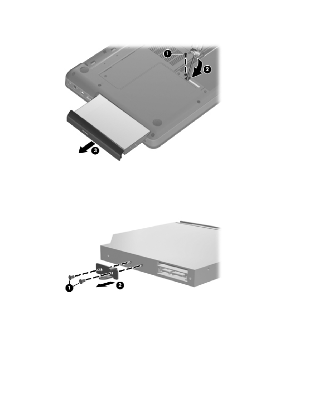
4. Remove the optical drive (3).
5. If it is necessary to replace the optical drive bracket, position the optical drive with the optical
drive bracket toward you.
6. Remove the two Phillips PM2.0×3.0 screws (1) that secure the optical drive bracket to the optical
drive.
7. Remove the optical drive bracket (2).
Reverse the above procedure to reassemble and install the optical drive.
ENWW Component replacement procedures 57
Page 68

WLAN module
Description Spare part
Atheros AR9285 802.11 a/b/g/n 2x2 WiFi adapter for use in Canada, the Cayman Islands, Guam,
Puerto Rico, the United States, and the US Virgin Islands
Atheros AR9285 802.11 a/b/g/n 2x2 WiFi adapter for use in Afghanistan, Albania, Algeria, Andorra,
Angola, Antigua and Barbuda, Argentian, Armenia, Australia, Austria, Azerbaijan, Bahamas, Bahrain,
Barbados, Belgium, Belize, Benin, Bhutan, Bosnia and Herzegovina, Botswana, Brazil, Brunei,
Bulgeria, Burkina Faso, Burundi, Cambodia, Cameroon, Cape Verde, Central African Republic, Chad,
Chile, China, Colombia, Comoros, Congo, Costa Rica, Croatia, Cyprus, Czech Republic, Zaire,
Denmark, Djibouti, Dominica, Dominican Republic, Ecuador, Egypt, El Salvador, Equitorial Guinea,
Eritrea, Estonia, Ethiopia, Fiji, Finland, France, Gabon, Gambia, Georgia, Germany, Ghana, Gibraltar,
Greece, Grenada, Guatemala, Guinea, Guinea-Bissa, Guyana, Haiti, Honduras, Hong Kong, Hungary,
Iceland, India, Indonesia, Ireland, Italy, Ivory Coast, Jamaica, Japan, Jordan, Kazakhstan, Kenya,
Kiribati, Korea-South, Kuwait, Kyrgyzstan, Laos, Latvia, Lebanon, Lesotho, Liberia, Martinique, Nether
Antilles, French Guiana, Aruba, British Virgin Islands, Bermuda, Syria, Guadeloupe, Liechtenstein,
Lithuania, Luxembourg, Macedonia, Madagaascar, Malawi, Malaysia, Maldives, Mali, Malta, Marshall
Islands, Mauritania, Mauritius, Mexico, Micronesia, Monaco, Mongolia, Montenegro, Morocco,
Mozambique, Namibia, Nauru, Nepal, Netherlands, New Zealand, Nicaragua, Niger, Nigeria, Norway,
Oman, Palau, Panama, Papua New Guinea, Paraguay, Peru, Philippines, Poland, Portugal, Republic of
Moldova, Romania, rwanda, Samoa, San Marino, Sao tome and Principe, Saudi Arabia, Senegal,
Serbia and Montenegro, Seychelles, Sierra Leone, Singapore, Slovakia, Slovenia, Solomon Islands,
Somalia, South Africa, Spain, Sri Lanka, St. Kitts and Nevis, St. Lucia, St. Vincent and Gren, Suriname,
Swaziland, Sweden, Switzerland, Taiwan, Tajikistan, Tanzania, Thailand, Timor (East), Togo, Tonga,
Trinidad and Tobago, Tunisia, Turkey, Turkmenistan, Tuvalu, Uganda, United Arab Emirates ,United
Kingdom, Uruguay, Uzbekistan, Vanuatu, Venezuela, Vietnam, Yemen, Zambia, and Zimbabwe
Intel Centrino Wireless-N 1000 802.11b/g/n 1x2 593530-001
number
580101-001
580101-002
Broadcom 4312G 802.11b/g WiFi Adapter for use in Canada, Cayman Islands, Guam, Puerto Rico, the
United States, and the U.S. Virgin Islands (for models 1.0 and 1.1 only)
Broadcom 4312G 802.11b/g WiFi Adapter for use in Afghanistan, Albania, Algeria, Andorra, Angola,
Antigua and Barbuda, Argentina, Armenia, Aruba, Australia, Austria, Azerbaijan, The Bahamas,
Bahrain, Bangladesh, Barbados, Belgium, Belize, Benin, Bermuda, Bhutan, Bolivia, Bosnia and
Herzegovina, Botswana, Brazil, The British Virgin Islands, Brunei, Bulgaria, Burkina Faso, Burundi,
Cameroon, Cape Verde, the Central African Republic, Chad, Chile, China, Colombia, Comoros, Congo,
Costa, Rica, Croatia, Cyprus, The Czech Republic, Denmark, Djibouti, Dominica, The Dominican
Republic, East Timor , Ecuador, Egypt, El Salvador, Equitorial Guinea, Eritrea, Estonia, Ethiopia, Fiji,
Finland, France, French, Guiana, Gabon, Gambia, Georgia, Germany, Ghana, Gibraltar, Greece,
Grenada, Guadeloupe, Guatemala, Guinea, Guinea-Bissa, Guyana, Haiti, Honduras, Hong Kong,
Hungary, Iceland, India, Ireland, Italy, The Ivory Coast, Jamaica, Jordan, Kazakhstan, Kenya, Kiribati,
Kyrgyzstan, Laos, Latvia, Lebanon, Lesotho, Liberia, Liechtenstein, Lithuania, Luxembourg, Macedonia,
Madagascar, Malawi, The Maldives, Mali, Malta, The Marshall Islands, Martinique, Mauritania,
Mauritius, Mexico, Micronesia, Monaco, Mongolia, Montenegro, Morocco, Mozambique, Namibia,
Nauru, Nepal, The Nether Antilles, The Netherlands, New Zealand, Nicaragua, Niger, Nigeria, Norway,
Oman, Pakistan, Palau, Panama, Papua New Guinea, Paraguay, Peru, The Philippines, Poland,
Portugal, Puerto Rico, The Republic of Moldova, Romania, Russia, Rwanda, Samoa, San Marino, Sao
Tome and Principe Saudi Arabia, Senegal, Serbia and Montenegro, The Seychelles, Sierra Leone,
Singapore, Slovakia, Slovenia, The Solomon Islands, Somalia, South Africa, Spain, Sri Lanka, St. Kitts
& Nevis, St. Lucia, St. Vincent and Gren, Suriname, Swaziland, Sweden, Switzerland, Taiwan,
Tajikistan, Tanzania, Togo, Tonga, Trinidad and Tobago, Tunisia, Turkey, Turkmenistan, Tuvalu,
Uganda, The United Arab Emirates, The United Kingdom, Uruguay, Uzbekistan, Vanuatu, Venezuela,
Vietnam, Yemen, Zaire, Zambia and Zimbabwe (for models 1.0 and 1.1 only)
Realtek RTL8191SE 802.11b/g/n 1x1 WiFi Adapter (for models 1.0, 1.1 and 1.2 only) 593533-001
Ralink RT3090BC4 802.11b/g/n 1x1 WiFi and Bluetooth 2.1+EDR Combo Adapter (BT3.0+HS ready)
(for model 1.2 and 1.3 only)
582562-001
582562-002
602992-001
58 Chapter 4 Removal and replacement procedures ENWW
Page 69

Description Spare part
number
Broadcom 4313 802.11b/g/n 1x1 WiFi and 2070 Bluetooth 2.1+EDR Combo adapter (BT3.0+HS ready)
(for models 1.2 and 1.3 only)
Ralink 5390GN 802.11b/g/n 1x1 WiFi Adapter (for model 1.3 only) 630703-001
600370-001
Before removing the WLAN module, follow these steps:
1. Shut down the computer. If you are unsure whether the computer is off or in Hibernation, turn
the computer on, and then shut it down through the operating system.
2. Disconnect all external devices connected to the computer.
3. Disconnect the power from the computer by first unplugging the power cord from the AC outlet
and then unplugging the AC adapter from the computer.
4. Remove the battery (see
5. Remove the hard drive cover (see
Battery on page 52).
Hard drive on page 53).
Remove the WLAN module:
1. Turn the computer upside down with the front toward you.
2. Loosen the 2 Phillips PM2.5×5.0 captive screws (1) that secure the mini-card compartment
cover.
3. Lift the cover off the computer (2). The mini-card compartment cover is included in the plastics
kit, spare part number 600190-001.
4. Disconnect the two WLAN antenna cables (1) from the WLAN module.
5. Remove the Phillips PM2.0×3.0 screw (2) that secures the WLAN module to the computer. (The
edge of the module opposite the slot rises away from the computer.)
ENWW Component replacement procedures 59
Page 70

6. Remove the WLAN module (3) by pulling it away from the slot at an angle.
CAUTION: To prevent an unresponsive system, replace the wireless module only with a
wireless module authorized for use in the computer by the governmental agency that regulates
wireless devices in your country or region. If you replace the module and then receive a warning
message, remove the module to restore computer functionality, and then contact technical
support through Help and Support.
NOTE: WLAN modules are designed with a notch (4) to prevent incorrect insertion into the
WLAN module slot.
Reverse this procedure to install a WLAN module.
60 Chapter 4 Removal and replacement procedures ENWW
Page 71

Memory module
Description Spare part number
2-MB, PC3 10600, 1333-MHz 598856-001
1-MB, PC3 10600, 1333-MHz 598859-001
4-MB, PC3 10600, 1333-MHz (for models 1.2 and 1.3 only) 599092-001
Before removing the memory module, follow these steps:
1. Shut down the computer. If you are unsure whether the computer is off or in Hibernation, turn
the computer on, and then shut it down through the operating system.
2. Disconnect all external devices connected to the computer.
3. Disconnect the power from the computer by first unplugging the power cord from the AC outlet
and then unplugging the AC adapter from the computer.
4. Remove the battery (see
Battery on page 52).
Remove the memory module:
1. Turn the computer upside down with the front toward you.
2. Loosen the two Phillips PM2.5×5.0 captive screws that secure the mini-card compartment cover
to the computer.
ENWW Component replacement procedures 61
Page 72

3. Lift cover off the computer. The mini-card compartment cover is included in the plastics kit, spare
part number 600190-001.
NOTE: Small tabs hold the cover in place. Firmly pull up on the cover to release the tabs.
4. Spread the retaining tabs (1) on each side of the memory module slot to release the memory
module. (The edge of the module opposite the slot rises away from the computer.)
5. Remove the module (2) by pulling it away from the slot at an angle.
NOTE: Memory modules are designed with a notch (3) to prevent incorrect insertion into the
memory module slot.
Reverse this procedure to install a memory module.
62 Chapter 4 Removal and replacement procedures ENWW
Page 73

Keyboard
Description Spare part number
Keyboard for use in Brazil 600175-201
Keyboard for use in Canada (English and French) 600175-121
Keyboard for use in for use in Latin America 600175-161
Keyboard for use in South Korea 600175-AD1
Keyboard for use in Taiwan 600175-AB1
Keyboard for use in Thailand 600175-281
Keyboard for use in the United States 600175-001
Before removing the keyboard, follow these steps:
1. Shut down the computer. If you are unsure whether the computer is off or in Hibernation, turn
2. Disconnect all external devices connected to the computer.
3. Disconnect the power from the computer by first unplugging the power cord from the AC outlet
the computer on, and then shut it down through the operating system.
and then unplugging the AC adapter from the computer.
4. Remove the battery (see
5. Remove the hard drive (see
6. Remove the mini-card compartment cover (see
Battery on page 52).
Hard drive on page 53)
WLAN module on page 58).
Remove the keyboard:
1. Turn the computer upside down with the front toward you.
2. Remove the six Phillips PM2.5×6.5 screws that secure the keyboard to the computer.
3. Turn the computer display-side up with the front toward you.
4. Open the computer as far as possible.
ENWW Component replacement procedures 63
Page 74
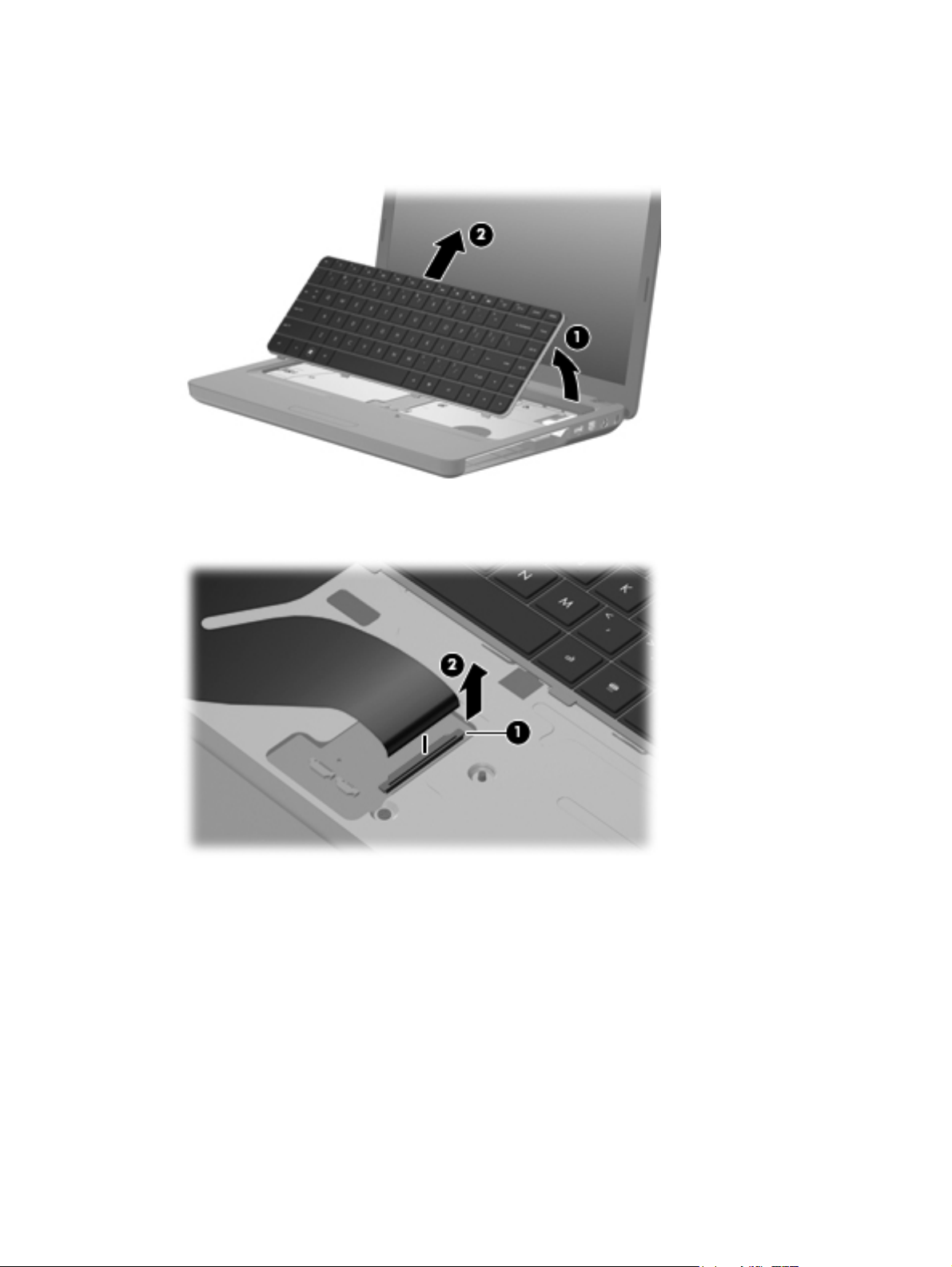
5. Release the top edge of the keyboard by lifting it up to disengage the keyboard from the tabs on
the top cover (1).
6. Slide the top edge of the keyboard back (2) until it rests against the display.
7. Release the zero insertion force (ZIF) connector (1) to which the keyboard cable is attached and
disconnect the keyboard cable (2) from the system board.
8. Remove the keyboard.
Reverse this procedure to install the keyboard.
64 Chapter 4 Removal and replacement procedures ENWW
Page 75

Top cover
Description Spare part number
Top cover (includes Touchpad and bracket, button board, and cable), matte black (for models 1.0,
1.1 and 1.3 only)
Top cover, biscotti 600182-001
Top cover, silver (for models 1.1, 1.2 and 1.3 only) 606161-001
Top cover, white (for model 1.1 only) 606162-001
Top cover, charcoal (for models 1.2 and 1.3 only) 622581-001
Top cover, imperial blue (for models 1.2 and 1.3 only) 622582-001
Top cover, velvet red (for models 1.2 and 1.3 only) 624971-001
600181-001
Before removing the switch cover, follow these steps:
1. Shut down the computer. If you are unsure whether the computer is off or in Hibernation, turn
the computer on, and then shut it down through the operating system.
2. Disconnect all external devices connected to the computer.
3. Disconnect the power from the computer by first unplugging the power cord from the AC outlet
and then unplugging the AC adapter from the computer.
4. Remove the following components:
a. Battery (see
b. Optical drive (see
c. Keyboard (see
Battery on page 52).
Optical drive on page 56).
Keyboard on page 63).
Remove the switch cover:
1. Turn the computer upside down with the front toward you.
2. Remove the four screw covers (1) at the front edge of the computer.
ENWW Component replacement procedures 65
Page 76

3. Remove the five Phillips PM2.5×6.5 screws (2), the two Phillips PM2.5x4.0 screws (3), and the
four Phillips PM2.5x3.0 screws (4) that secure the top cover to the base enclosure.
4. Turn the computer display-side up with the front toward you.
5. Open the computer as far as possible.
6. Release the ZIF connector to which the touchpad (1) is connected and disconnect the cable
from the system board.
7. Release the ZIF connector to which the touchpad button board cable (2) is connected and
disconnect the cable from the system board.
8. Disconnect the speaker cable (3) from the system board.
66 Chapter 4 Removal and replacement procedures ENWW
Page 77

9. Release the ZIF connector to which the power button board cable (4) is connector and
disconnect the cable from the system board.
10. Remove the Phillips PM2.5×6.5 screw (1) from the top cover, disengage the rear edge of the top
cover (2) from the base enclosure, and then remove the cover from the computer (3).
Reverse this procedure to install the switch cover.
ENWW Component replacement procedures 67
Page 78

Speaker assembly
Description Spare part number
Speaker assembly 600189-001
Before removing the speaker assembly, follow these steps:
1. Shut down the computer. If you are unsure whether the computer is off or in Hibernation, turn
the computer on, and then shut it down through the operating system.
2. Disconnect all external devices connected to the computer.
3. Disconnect the power from the computer by first unplugging the power cord from the AC outlet
and then unplugging the AC adapter from the computer.
4. Remove the battery (see
Battery on page 52).
5. Remove the following components:
a. Optical drive (see
b. Keyboard (see
c. Top cover (see
Optical drive on page 56)
Keyboard on page 63)
Top cover on page 65)
Remove the speaker assembly:
1. Turn the top cover upside down.
2. Remove the two Phillips PM2.5×4.0 screws (1) that secure the speaker assembly to the
computer.
3. Lift the speaker assembly (2) straight up to remove it from the top cover.
Reverse this procedure to install the speaker assembly.
68 Chapter 4 Removal and replacement procedures ENWW
Page 79

Power button board
Description Spare part number
Power button board (with cable) 600188-001
Before removing the power button board, follow these steps:
1. Shut down the computer. If you are unsure whether the computer is off or in Hibernation, turn
the computer on, and then shut it down through the operating system.
2. Disconnect all external devices connected to the computer.
3. Disconnect the power from the computer by first unplugging the power cord from the AC outlet
and then unplugging the AC adapter from the computer.
4. Remove the battery (see
Battery on page 52).
5. Remove the following components:
a. Hard drive (see
b. Optical drive (see
c. Keyboard (see
d. Top cover (see
Hard drive on page 53)
Optical drive on page 56)
Keyboard on page 63)
Top cover on page 65)
Remove the power button board:
1. Turn the top cover upside down with the rear edge toward you.
2. Remove the Phillips PM2.5×3.0 screw (1) that secures the power button board to the top cover.
3. Remove the power button board (2).
ENWW Component replacement procedures 69
Page 80

TouchPad button board
Description Spare part number
TouchPad button board 604603-001
Before removing the TouchPad button board, follow these steps:
1. Shut down the computer. If you are unsure whether the computer is off or in Hibernation, turn
the computer on, and then shut it down through the operating system.
2. Disconnect all external devices connected to the computer.
3. Disconnect the power from the computer by first unplugging the power cord from the AC outlet
and then unplugging the AC adapter from the computer.
4. Remove the battery (see
Battery on page 52).
5. Remove the following components:
a. Hard drive (see
b. Optical drive (see
c. Keyboard (see
d. Top cover (see
Hard drive on page 53)
Optical drive on page 56)
Keyboard on page 63)
Top cover on page 65)
Remove the TouchPad button board:
1. Turn the top cover upside down with the front toward you.
2. Remove the two Phillips PM2.5×3.0 screws (1) that secure the TouchPad board to the top cover.
3. Remove the TouchPad button board (2) from the TouchPad bracket.
Reverse the above procedure to reassemble and install the TouchPad button board.
70 Chapter 4 Removal and replacement procedures ENWW
Page 81

Modem module
Description Spare part number
High-speed 56K modem for use in all countries and regions except Australia and New Zealand
(for models 1.0 and 1.1 only)
High-speed 56K modem for use in Australia and New Zealand (for models 1.0 and 1.1 only) 510100-011
Modem module cable with RJ-11 connector (included in the cable kit) 610791-001
510100-001
Before removing the modem module, follow these steps:
1. Shut down the computer. If you are unsure whether the computer is off or in Hibernation, turn
the computer on, and then shut it down through the operating system.
2. Disconnect all external devices connected to the computer.
3. Disconnect the power from the computer by first unplugging the power cord from the AC outlet
and then unplugging the AC adapter from the computer.
4. Remove the battery (see
Battery on page 52).
5. Remove the following components:
a. Hard drive (see
b. Optical drive (see
c. Keyboard (see
Hard drive on page 53)
Optical drive on page 56)
Keyboard on page 63)
d. Top cover (see
Top cover on page 65)
Remove the modem module:
1. Turn the computer upright with the front toward you.
2. Remove the two Phillips PM2.0×3.0 screws (1) that secure the modem module to the system
board.
3. Disconnect the modem module cable (2) from the modem module.
ENWW Component replacement procedures 71
Page 82

4. Lift up on the front of the modem module (3) to disconnect it from the system board.
5. Remove the modem module.
Reverse the above procedure to install the modem module, and be sure that the connector on the
bottom of the modem module connects firmly into the system board.
72 Chapter 4 Removal and replacement procedures ENWW
Page 83

Bluetooth module
Description Spare part number
Bluetooth module (for models 1.0, 1.1 and 1.3 only) 537921-001
Bluetooth module cable (for models 1.0, 1.1 and 1.3 only) 602822-001
Before removing the Bluetooth module, follow these steps:
1. Shut down the computer. If you are unsure whether the computer is off or in Hibernation, turn
the computer on, and then shut it down through the operating system.
2. Disconnect all external devices connected to the computer.
3. Disconnect the power from the computer by first unplugging the power cord from the AC outlet
and then unplugging the AC adapter from the computer.
4. Remove the battery (see
Battery on page 52).
5. Remove the following components:
a. Hard drive (see
b. Optical drive (see
c. Keyboard (see
d. Top cover (see
Hard drive on page 53)
Optical drive on page 56)
Keyboard on page 63)
Top cover on page 65)
Remove the Bluetooth module:
1. Position the computer upright with the front toward you.
2. Disconnect the Bluetooth module cable (1) from the system board.
3. Remove the Bluetooth module and cable from the clips in the base enclosure (2).
4. Remove the Bluetooth module (3) from the base enclosure.
Reverse the above procedure to install the Bluetooth module.
ENWW Component replacement procedures 73
Page 84

USB board
Description Spare part number
USB board (includes cable) 600631-001
Before removing the USB board, follow these steps:
1. Shut down the computer. If you are unsure whether the computer is off or in Hibernation, turn
2. Disconnect all external devices connected to the computer.
3. Disconnect the power from the computer by first unplugging the power cord from the AC outlet
the computer on, and then shut it down through the operating system.
and then unplugging the AC adapter from the computer.
4. Remove the battery (see
Battery on page 52).
5. Remove the following components:
a. Hard drive (see
b. Optical drive (see
c. Keyboard (see
d. Top cover (see
Hard drive on page 53)
Optical drive on page 56)
Keyboard on page 63)
Top cover on page 65)
Remove the USB board:
1. Position the computer upright with the right side toward you.
2. Disconnect the USB board cable (1) from the system board.
3. Remove the Phillips PM2.5×3.0 screw (2) that secures the USB board to the base enclosure.
4. Lift the USB board (3) straight up to remove it from the computer.
Reverse this procedure to install the USB board.
74 Chapter 4 Removal and replacement procedures ENWW
Page 85

Power connector cable
Description Spare part number
Power connector cable (includes cable and connector) 600188-001
Before removing the power connector cable, follow these steps:
1. Shut down the computer. If you are unsure whether the computer is off or in Hibernation, turn
the computer on, and then shut it down through the operating system.
2. Disconnect all external devices connected to the computer.
3. Disconnect the power from the computer by first unplugging the power cord from the AC outlet
and then unplugging the AC adapter from the computer.
4. Remove the battery (see
Battery on page 52).
5. Remove the following components:
a. Hard drive (see
b. Optical drive (see
c. Keyboard (see
d. Top cover (see
Hard drive on page 53)
Optical drive on page 56)
Keyboard on page 63)
Top cover on page 65))
Remove the power connector cable:
1. Turn the computer upright with the right side toward you.
2. Disconnect the power connector cable (1) from the system board.
3. Lift the power connector (2) from the clips built into the base enclosure.
4. Remove the cable from the base enclosure.
Reverse this procedure to install the power connector cable.
ENWW Component replacement procedures 75
Page 86

Display assembly
Description Spare part number
35.6 cm (14-in) WXGA Brightview display assembly for use with integrated microphone and
webcam; Presario, matte black
35.6 cm (14-in) WXGA Brightview display assembly for use with integrated microphone and
webcam; Presario, biscotti
35.6 cm (14-in) WXGA Brightview display assembly for use with integrated microphone and
webcam; HP, biscotti
35.6 cm (14-in) WXGA Brightview display assembly for use with integrated microphone and
webcam; HP, silver (for models 1.1, 1.2 and 1.3 only)
35.6 cm (14-in) WXGA Brightview display assembly for use with integrated microphone and
webcam; HP, white (for model 1.1 only)
35.6 cm (14-in) WXGA Brightview display assembly for use with integrated microphone and
webcam; HP, charcoal (for models 1.2 and 1.3 only)
35.6 cm (14-in) WXGA Brightview display assembly for use with integrated microphone and
webcam; HP, imperial blue (for models 1.2 and 1.3 only)
35.6 cm (14-in) WXGA Brightview display assembly for use with integrated microphone and
webcam; Presario, velvet red (for model 1.2 only)
35.6 cm (14-in) WXGA Brightview display assembly for use with integrated microphone and
webcam; HP, velvet red (for models 1.2 and 1.3 only)
Before removing the display assembly, follow these steps:
592146-001
597617-001
600163-001
606155-001
606156-001
622571-001
622572-001
624966-001
630907-001
1. Shut down the computer. If you are unsure whether the computer is off or in Hibernation, turn
the computer on, and then shut it down through the operating system.
2. Disconnect all external devices connected to the computer.
3. Disconnect the power from the computer by first unplugging the power cord from the AC outlet
and then unplugging the AC adapter from the computer.
4. Remove the battery (see
5. Disconnect the wireless antenna cables from the WLAN module (see
Battery on page 52).
WLAN module
on page 58).
6. Remove the following components:
a. Keyboard (see
b. Optical drive (see
c. Top cover (see
Keyboard on page 63)
Optical drive on page 56)
Top cover on page 65)
Remove the display assembly:
1. Turn the computer display-side up, with the front toward you.
2. Open the display as far as possible.
3. Remove the wireless antenna cables (1) from the hole and clips built into the base enclosure.
76 Chapter 4 Removal and replacement procedures ENWW
Page 87

4. Disconnect the display panel cable (2) from the system board.
5. Disconnect the microphone cable (3) from the system board.
6. Disconnect the webcam cable (2) from the system board.
CAUTION: Support the display assembly when removing the display screws in the following
steps. Failure to support the display assembly can result in damage to the assembly and other
components.
7. Remove the four black Phillips PM2.5×6.5 screws (1) that secure the display assembly to the
computer.
8. Remove the display assembly (2).
ENWW Component replacement procedures 77
Page 88

9. If it is necessary to replace any of the display assembly internal components, remove the
following screw covers and screws. The display screw covers are included in the display screw
kit, spare part number 592152-001.
(1) Two Mylar screw covers on the display bezel bottom edge
(2) Two Phillips PM2.5×4.0 screws
10. Flex the inside edge of the top (1), the left and right sides (2), and the bottom (3) of the display
bezel until the bezel disengages from the display back cover.
11. Remove the display bezel (4). The display bezel is available using spare part number
592147-001 for HP computers, and 592148-001 for Presario computers.
78 Chapter 4 Removal and replacement procedures ENWW
Page 89

12. If it is necessary to replace the webcam module, disconnect the webcam cable (1) from the
module. Lift the webcam from the double-sided tape on the display back cover, and remove the
webcam.
13. If it is necessary to replace the display panel, remove the eight Phillips PM2.5×5.0 screws (1)
that secure the display panel to the display enclosure, and then lift the panel from the enclosure
(2). The display panel is available using the spare part number 592144-001.
14. If it is necessary to replace the display cable, follow these steps:
a. Turn the display panel upside down in front of you.
b. Peel back the tape that secures the cable to the display (1).
c. Unplug the cable from the display (2).
d. Remove the cable from the display (3).
ENWW Component replacement procedures 79
Page 90
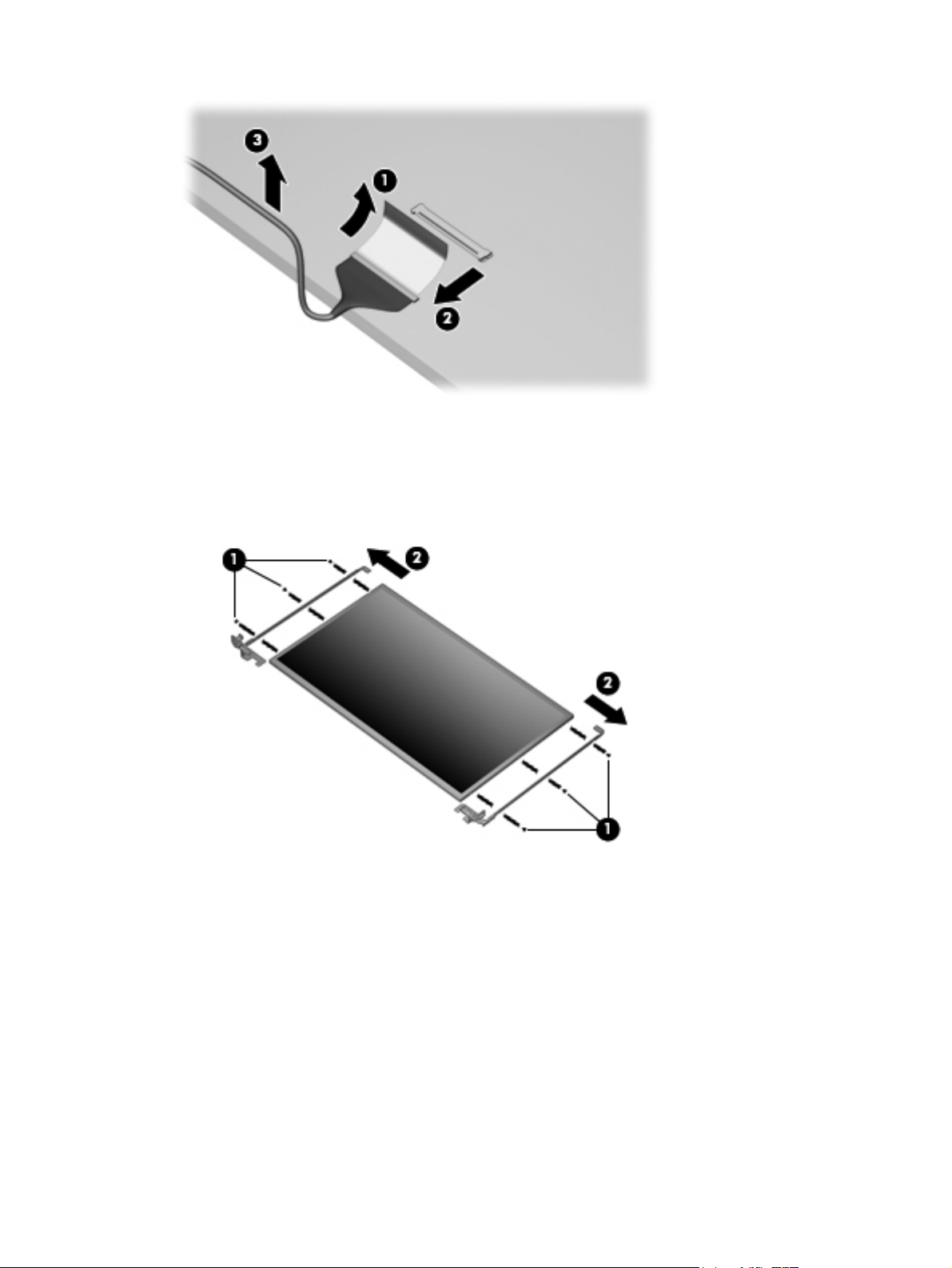
The display cable is available in the display cable kit, spare part number 592151-001.
15. If it is necessary to replace the display bracket and hinges, remove the Phillips PM2.0×3.0
screws (1) that secure each bracket to the display.
16. Remove the display hinges (2) from the display. The display bracket and hinge set is available
using spare part number 600627-001.
17. If it is necessary to replace the wireless antennas and cables, remove the adhesive strip (1) that
secures each antenna to the display back cover.
18. Detach the wireless antenna (2) from the display back cover .
19. Remove the antenna cables from the clips (3) built into the display enclosure.
80 Chapter 4 Removal and replacement procedures ENWW
Page 91

20. Remove the wireless antennas and cables (4) from the display enclosure. The wireless
antennas and cables are included in the display cable kit, spare part number 592151-001.
21. If it is necessary to remove the webcam cable, remove the cable from the adhesive strips (1)
along the cable path on the display back cover, and then remove the webcam cable (2). The
webcam cable is included in the display cable kit, spare part number 592151-001,
ENWW Component replacement procedures 81
Page 92

22. If it is necessary to remove the microphone, release the microphone cable from the adhesive
strips (1) along the cable path on the display back cover, remove the microphone from the clips
on the display back cover (2), and then remove the microphone and microphone cable (3). The
microphone and cable is included in the display cable kit, spare part number 592151-001,
Reverse this procedure to reassemble and install the display assembly.
82 Chapter 4 Removal and replacement procedures ENWW
Page 93

System board
Description Spare part number
System board for use in models with discrete graphics subsystem (for models 1.0 and 1.1 only) 595181-001
System board for use in models with Unified Memory Architecture (UMA) graphics subsystem 595182-001
System board for use in models with discrete graphics subsystem and HDMI card reader (for
models 1.0, 1.1 and 1.2 only)
System board for use in models with UMA graphics subsystem and HDMI card reader 595184-001
System board for use in models with UMA graphics subsystem memory, Intel GL40 chipset, and
HDMI card reader
System board for use in HM55 HD5430/1 G discrete subsystem (for model 1.1 only) 608823-001
System board for use in HD5430/1 G discrete subsystem with HDMI card reader (for model 1.1
only)
System board for use in HM55 HD545V discrete subsystem (for model 1.1 only) 615577-001
System board for use in HM55 HD545V discrete subsystem with HDMI card reader (for model 1.1
only)
System board for use in HD5470/512 MB discrete subsystem (for model 1.2 only) 615579-001
System board for use in HD5470/512 MB discrete subsystem with HDMI card reader (for model
1.2 only)
System board for use in HD5470/1 GB discrete subsystem (for model 1.2 only) 615581-001
System board for use in HD5470/1 GB discrete subsystem with HDMI card reader (for model 1.2
only)
System board for use in HD6370/512 subsystem with HDMI card reader (for model 1.3 only) 631593-001
System board for use in HD6370/1-GB (for model 1.3 only) 631594-001
595183-001
605140-001
608824-001
615578-001
615580-001
615582-001
System board for use in HD6370/512M with HDMI reader card (for model 1.3 only) 631595-001
System board for use in HD6370/512M i3-370M with HDMI (for model 1.3 only) 631596-001
System board for use in i3-350M UMA subsystems (for model 1.3 only) 634648-001
System board for use in i3-370M UMA subsystems (for model 1.3 only) 637583-001
System board for use in HD6370/512M i3-370M (for model 1.3 only) 637584-001
System board GL40 UMA HDMI ROM 2M (for model 1.3 only) 639266-001
When replacing the system board, be sure that the following components are removed from the
defective system board and installed on the replacement system board:
RTC battery (see
●
Memory modules (see
●
WLAN module (see
●
Modem module (see
●
RTC battery on page 89)
Memory module on page 61)
WLAN module on page 58)
Modem module on page 71)
ENWW Component replacement procedures 83
Page 94

Before removing the system board, follow these steps:
1. Shut down the computer. If you are unsure whether the computer is off or in Hibernation, turn
the computer on, and then shut it down through the operating system.
2. Disconnect all external devices connected to the computer.
3. Disconnect the power from the computer by first unplugging the power cord from the AC outlet
and then unplugging the AC adapter from the computer.
4. Remove the battery (see
5. Remove the following components:
a. Hard drive (see
b. WLAN (see
c. Optical drive (see
d. Keyboard (see
e. Top cover (see
f. Speaker assembly (see
g. Display assembly (see
h. Top cover (see
Remove the following cables from the system board if still connected:
Power connector cable (see
●
Bluetooth cable (see
●
USB board cable (see
●
WLAN module on page 58)
Battery on page 52).
Hard drive on page 53)
Optical drive on page 56)
Keyboard on page 63)
Top cover on page 65)
Speaker assembly on page 68)
Display assembly on page 76)
Top cover on page 65)
Power connector cable on page 75)
Bluetooth module on page 73)
USB board on page 74)
1. Turn the computer upright with the right side toward you.
2. Remove the three Phillips PM2.5×3.0 screws that secure the system board to the computer.
84 Chapter 4 Removal and replacement procedures ENWW
Page 95
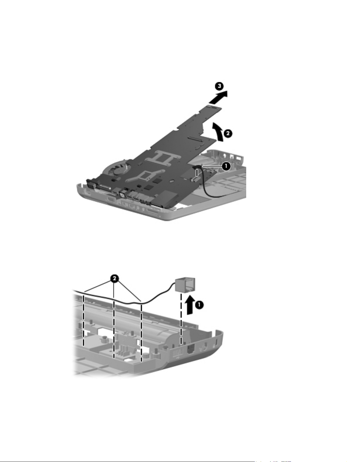
3. Release the optical drive cable (1) from the system board.
4. Lift the right side of the system board (2).
5. Release the system board by sliding it to the right at an angle (3) until the connectors on the left
side of the system board clear the base enclosure, and then remove the system board.
6. If it is necessary to replace the modem module cable, remove the RJ-11 connector (1) from the
clip built into the base enclosure.
7. Remove the modem module cable (2) from the routing channel built into the base enclosure.
The modem module cable is available using spare part number 610791-001.
ENWW Component replacement procedures 85
Page 96

When replacing the system board, be sure that the following components are removed from the
defective system board and installed on the replacement system board:
Fan/heat sink assembly (see
●
Processor (see
●
Reverse the preceding procedure to install the system board.
Processor on page 94)
Fan/heat sink assembly on page 91)
86 Chapter 4 Removal and replacement procedures ENWW
Page 97

Optical drive SATA cable and connector
Description Spare part number
Optical drive cable (included in the cable kit) 610791-001
Before removing the optical drive cable, follow these steps:
1. Shut down the computer. If you are unsure whether the computer is off or in Hibernation, turn
the computer on, and then shut it down through the operating system.
2. Disconnect all external devices connected to the computer.
3. Disconnect the power from the computer by first unplugging the power cord from the AC outlet
and then unplugging the AC adapter from the computer.
4. Remove the battery (see
Battery on page 52).
5. Remove the following components:
a. Hard drive (see
b. WLAN (see
c. Optical drive (see
d. Keyboard (see
e. Top cover (see
f. Speaker assembly (see
g. Display assembly (see
h. System board (see
Hard drive on page 53)
WLAN module on page 58)
Optical drive on page 56)
Keyboard on page 63)
Top cover on page 65)
Speaker assembly on page 68)
Display assembly on page 76)
System board on page 83)
Remove the optical drive cable
1. Remove the two Phillips PM2.5×6.0 screws (1) that secure the optical drive connector to the
system board.
ENWW Component replacement procedures 87
Page 98

2. Release the cable from the clips on the base enclosure (2), and then remove the cable (3).
88 Chapter 4 Removal and replacement procedures ENWW
Page 99

RTC battery
Description Spare part number
RTC battery 602745-001
Before removing the RTC battery, follow these steps:
1. Shut down the computer. If you are unsure whether the computer is off or in Hibernation, turn
the computer on, and then shut it down through the operating system.
2. Disconnect all external devices connected to the computer.
3. Disconnect the power from the computer by first unplugging the power cord from the AC outlet
and then unplugging the AC adapter from the computer.
4. Remove the battery (see
Battery on page 52).
5. Remove the following components:
a. Hard drive (see
b. WLAN (see
c. Optical drive (see
d. Keyboard (see
e. Top cover (see
f. Speaker assembly (see
g. Display assembly (see
h. System board (see
Hard drive on page 53)
WLAN module on page 58)
Optical drive on page 56)
Keyboard on page 63)
Top cover on page 65)
Speaker assembly on page 68)
Display assembly on page 76)
System board on page 83)
Remove the RTC battery:
1. Turn the system board upside down.
2. Release the RTC battery from the clips on the system board (1).
ENWW Component replacement procedures 89
Page 100

3. Remove the RTC battery (2).
Reverse this procedure to install the RTC battery.
90 Chapter 4 Removal and replacement procedures ENWW
 Loading...