

Page 1

b
Maintenance and Service Guide
Compaq Evo N200 Series
Document Part Number: 233117-001
September 2001
This guide is a troubleshooting reference used for maintaining
and servicing the notebook. It provides comprehensive
information on identifying computer features, components, and
spare parts, troubleshooting computer problems, and performing
computer disassembly procedures.
Page 2

© 2001 Compaq Computer Corporation
Compaq and the Compaq logo Registered in U. S. Patent and Trademark Office.
Evo is a trademark of Compaq Information Technologies Group, L.P.
Microsoft and Windows are trademarks of Microsoft Corporation.
Intel and Pentium are trademarks of Intel Corporation.
All other product names mentioned herein may be trademarks of their respective
companies.
Compaq shall not be liable for technical or editorial errors or omissions
contained herein. The information in this document is provided “as is” without
warranty of any kind and is subject to change without notice. the warranties for
Compaq products are set forth in the express limited warranty statements
accompanying such products. Nothing herein should be construed as
constituting an additional warranty.
Maintenance and Service Guide
First Edition (September 2001)
Document Part Number: 233117-001
Page 3

Contents
1 Product Description
1.1 Features . . . . . . . . . . . . . . . . . . . . . . . . . . . . . . . . . . . 1–2
1.2 Clearing a Password. . . . . . . . . . . . . . . . . . . . . . . . . . 1–4
1.3 Power Management . . . . . . . . . . . . . . . . . . . . . . . . . . 1–5
1.4 Computer External Components . . . . . . . . . . . . . . . . 1–6
1.4 Design Overview . . . . . . . . . . . . . . . . . . . . . . . . . . . 1–16
2 Troubleshooting
Using the PhoenixBIOS Setup Utility . . . . . . . . . . . . . . . 2–1
Troubleshooting Flowcharts. . . . . . . . . . . . . . . . . . . . . . . 2–2
Initial Troubleshooting . . . . . . . . . . . . . . . . . . . . . . . 2–3
2.2 No Power, Part 1 . . . . . . . . . . . . . . . . . . . . . . . . . 2–4
2.3 No Power, Part 2 . . . . . . . . . . . . . . . . . . . . . . . . . 2–5
2.4 No Power, Part 3 . . . . . . . . . . . . . . . . . . . . . . . . . 2–6
2.5 No Power, Part 4 . . . . . . . . . . . . . . . . . . . . . . . . . 2–7
2.6 No Video, Part 1 . . . . . . . . . . . . . . . . . . . . . . . . . 2–8
2.7 No Video, Part 2 . . . . . . . . . . . . . . . . . . . . . . . . . 2–9
2.8 Nonfunctioning Docking Station
(if applicable). . . . . . . . . . . . . . . . . . . . . . . . . . . . . . 2–10
2.9 No Operating System (OS) Loading . . . . . . . . . 2–11
2.10 No OS Loading from Hard Drive, Part 1. . . . . 2–12
2.11 No OS Loading from Hard Drive, Part 2. . . . . 2–13
2.12 No OS Loading from Hard Drive, Part 3. . . . . 2–14
2.13 No OS Loading from Diskette Drive. . . . . . . . 2–15
2.14 No OS Loading from CD- or
DVD-ROM Drive . . . . . . . . . . . . . . . . . . . . . . . . . . 2–16
2.15 No Audio, Part 1 . . . . . . . . . . . . . . . . . . . . . . . 2–17
2.16 No Audio, Part 2 . . . . . . . . . . . . . . . . . . . . . . . 2–18
Maintenance and Service Guide iii
Page 4

2.17 Nonfunctioning Device . . . . . . . . . . . . . . . . . . 2–19
2.18 Nonfunctioning Keyboard . . . . . . . . . . . . . . . . 2–20
2.19 Nonfunctioning Pointing Device. . . . . . . . . . . 2–21
2.20 Network or Modem Connection Problems . . . 2–22
3 Illustrated Parts Catalog
3.1 Serial Number Location . . . . . . . . . . . . . . . . . . . . . . . 3–1
3.2 Computer System Major Components. . . . . . . . . . . . 3–2
3.3 Miscellaneous Plastics Kit Components . . . . . . . . . . 3–6
3.4 Cable Kit Components . . . . . . . . . . . . . . . . . . . . . . . . 3–7
3.5 Miscellaneous Spare Parts . . . . . . . . . . . . . . . . . . . . . 3–8
4 Removal and Replacement Preliminaries
4.1 Tools Required. . . . . . . . . . . . . . . . . . . . . . . . . . . . . . 4–1
4.2 Service Considerations. . . . . . . . . . . . . . . . . . . . . . . . 4–2
Plastic Parts . . . . . . . . . . . . . . . . . . . . . . . . . . . . . . . . 4–2
Cables and Connectors . . . . . . . . . . . . . . . . . . . . . . . 4–2
4.3 Preventing Damage to Removable Drives . . . . . . . . . 4–3
4.4 Preventing Electrostatic Damage . . . . . . . . . . . . . . . . 4–4
4.5 Packaging and Transporting Precautions . . . . . . . . . . 4–4
4.6 Workstation Precautions . . . . . . . . . . . . . . . . . . . . . . 4–5
4.7 Grounding Equipment and Methods . . . . . . . . . . . . . 4–6
5 Removal and Replacement Procedures
5.1 Serial Number . . . . . . . . . . . . . . . . . . . . . . . . . . . . . . 5–2
5.2 Disassembly Sequence Chart . . . . . . . . . . . . . . . . . . . 5–3
5.3 Preparing the Computer for Disassembly . . . . . . . . . 5–4
5.4 Computer Feet . . . . . . . . . . . . . . . . . . . . . . . . . . . . . . 5–5
5.5 Modem/NIC . . . . . . . . . . . . . . . . . . . . . . . . . . . . . . . . 5–6
5.6 LED Cover . . . . . . . . . . . . . . . . . . . . . . . . . . . . . . . . . 5–9
5.7 Microphone . . . . . . . . . . . . . . . . . . . . . . . . . . . . . . . 5–10
5.8 Keyboard . . . . . . . . . . . . . . . . . . . . . . . . . . . . . . . . . 5–11
5.9 LED Board . . . . . . . . . . . . . . . . . . . . . . . . . . . . . . . . 5–12
5.10 Display . . . . . . . . . . . . . . . . . . . . . . . . . . . . . . . . . . 5–15
5.11 Top Cover. . . . . . . . . . . . . . . . . . . . . . . . . . . . . . . . 5–18
iv Maintenance and Service Guide
Page 5

5.12 RTC Battery . . . . . . . . . . . . . . . . . . . . . . . . . . . . . . 5–22
5.13 System Board . . . . . . . . . . . . . . . . . . . . . . . . . . . . . 5–24
5.14 Charger Board . . . . . . . . . . . . . . . . . . . . . . . . . . . . 5–27
5.15 Modem/NIC Cable . . . . . . . . . . . . . . . . . . . . . . . . . 5–29
5.16 Audio Cable . . . . . . . . . . . . . . . . . . . . . . . . . . . . . . 5–31
6 Specifications
A Connector Pin Assignments
B Power Cord Set Requirements
3-Conductor Power Cord Set . . . . . . . . . . . . . . . . . . . . . . B–1
General Requirements . . . . . . . . . . . . . . . . . . . . . . . . B–1
Country-Specific Requirements . . . . . . . . . . . . . . . . . . . . B–2
Notes . . . . . . . . . . . . . . . . . . . . . . . . . . . . . . . . . . . . . B–3
C Screw Listing
Index
Maintenance and Service Guide v
Page 6
Product Description
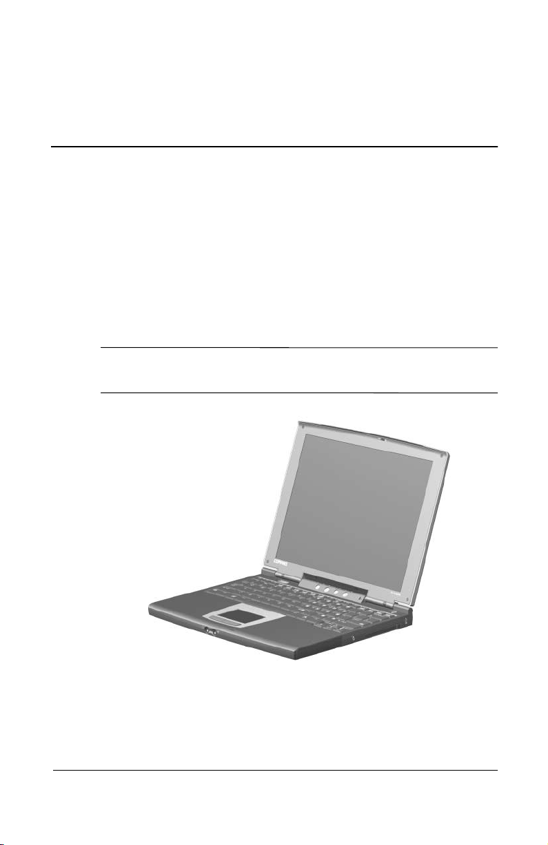
The Compaq Evo N200 Series of Personal Computers offers
advanced modularity, a 700-MHz Intel Pentium III processor
with 64-bit architecture, industry-leading Accelerated Graphics
Port (AGP) implementation, and extensive multimedia support.
The computer provides desktop functionality and connectivity
through the optional Mobile Expansion Unit (MEU).
All Evo N200 computer models have an SKU number of
✎
243420-B21 and a config. code of KCJZ.
1
Figure 1-1. Compaq Evo N200
Maintenance and Service Guide 1–1
Page 7

Product Description
1.1 Features
The computer has the following features:
Intel Pentium III 700-MHz processor, with 256-KB
■
integrated cache
ATI Mobility M1, 8-MB SDRAM
■
192 MB standard memory (64 MB integrated on system
■
board, 128 MB in memory expansion compartment)
Microsoft Windows 2000
■
10.4-inch, XGA, TFT (1024 × 768) display, with over 16.8
■
million colors
TouchPad pointing device
■
Mini PCI V.90 modem plus 10/100 NIC combination card
■
Support for one Type II PC Card slot with support for both
■
32-bit CardBus and 16-bit PC Cards
1–2 Maintenance and Service Guide
Page 8

Product Description
External AC adapter with power cord
■
Support for a 6-cell Lithium ion (Li ion) primary battery pack
■
in the battery bay and an optional external 4-cell Li ion
20-GB high-capacity hard drive
■
Speaker
■
Connectors for:
■
RJ-45 network
❏
RJ-11 modem
❏
External monitor
❏
Mobile Expansion Unit (MEU)
❏
Stereo speaker/headphone
❏
Microphone
❏
Universal serial bus (USB)
❏
AC power
❏
Maintenance and Service Guide 1–3
Page 9

Product Description
1.2 Clearing a Password
If the notebook you are servicing has an unknown password,
follow these steps to clear the password. These steps also clear
CMOS:
1. Prepare the computer for disassembly. Refer to Section 5.3,
“Preparing the Computer for Disassembly,” for more
information.
2. Remove the RTC battery (refer to Section 5.12, “RTC
Battery”).
3. Wait approximately five minutes.
4. Replace the RTC battery and reassemble the computer.
5. Connect AC power to the computer. Do not reinsert any
battery packs at this time.
6. Turn on the computer.
All passwords and all CMOS settings are clear.
1–4 Maintenance and Service Guide
Page 10

1.3 Power Management
The computer comes with a collection of power management
features that extends battery operating time and conserves power.
The computer supports the following power management
features:
Standby
■
Hibernation
■
Setting customization by the user
■
Hotkeys for setting level of performance
■
Smart battery that provides an accurate battery power gauge
■
Battery calibration
■
Lid switch suspend/resume
■
Power switch
■
Standby button
■
Advanced Configuration and Power Management (ACP)
■
compliance
Product Description
Maintenance and Service Guide 1–5
Page 11
Product Description
1.4 Computer External Components
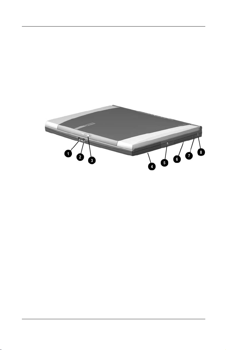
The external components on the display and right side of the
computer are shown in Figure 1-2 and described in Table 1-1.
.
Figure 1-2. Front and Right Side Components
1–6 Maintenance and Service Guide
Page 12

Tabl e 1-1
Front and Right Side Components
Item Component Function
Product Description
1 Stereo speaker/
headphone jack
Connects stereo speakers,
headphones, headset, or television
audio.
2 Microphone jack Connects a single sound channel
microphone.
3 Display release latch Releases the display to open the
computer.
4 Hard drive Supports the removable primary
hard drive.
5 Power jack Connects any one of the following:
■
AC adapter
■
Optional automobile power
adapter/charger
■
Optional aircraft power
adapter
6 PC Card slot Supports 32-bit (CardBus) and
16-bit PC Cards.
7 PC Card eject button Ejects a PC Card from the PC
Card slot.
8 Security cable slot Attaches an optional security cable
to the computer.
Maintenance and Service Guide 1–7
Page 13
Product Description
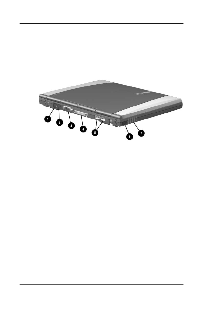
The computer rear panel and left side components are shown in
Figure 1-3 and described in Table 1-2.
Figure 1-3. Rear Panel and Left Side Components
1–8 Maintenance and Service Guide
Page 14

Tabl e 1 -2
Rear Panel and Left Side Components
Item Component Function
Product Description
1 RJ-45 jack (network models
only)
2 RJ-11 jack (internal modem
models only)
3 External monitor connector Connects an external monitor or
4 Docking connector Connects the computer to an
5 USB connectors (2) Connect USB devices.
6 Infrared port Links another IrDA-compliant
7 Vent Allows airflow to cool internal
Connects the network cable.
A network cable is
✎
included with network
models
Connects the modem cable to an
internal modem.
A modem cable is
✎
included with internal
modem models.
overhead projector.
optional Mobile Expansion Unit.
device for wireless communication.
components.
Maintenance and Service Guide 1–9
Page 15
Product Description
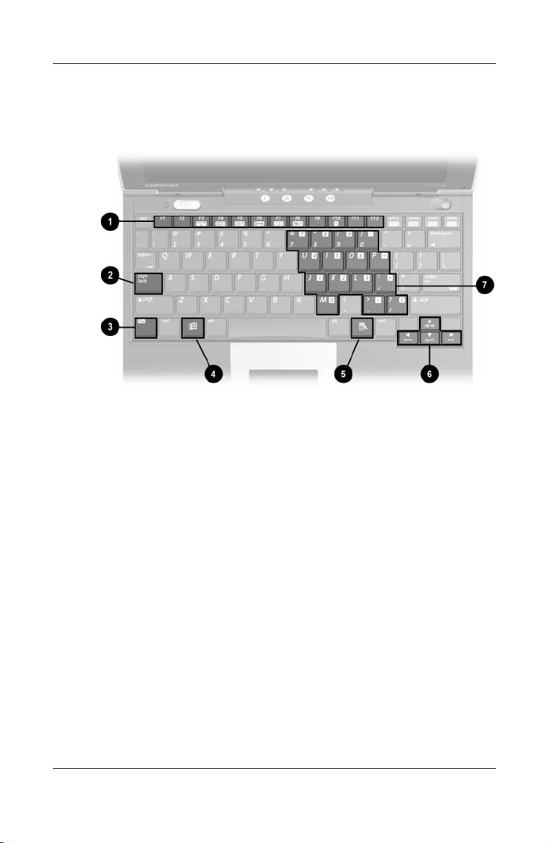
The keyboard components are shown in Figure 1-4 and described
in Table 1-3.
Figure 1-4. Keyboard Components
1–10 Maintenance and Service Guide
Page 16

Product Description
Tabl e 1-3
Keyboard Components
Item Component Function
1 F1 through F12 function keys Perform preset functions.
2 Caps lock key Turns on the caps lock function.
3 Fn key Used with hotkeys to perform
preset hotkey functions.
4 Windows logo key Displays Windows Start menu.
5 Windows application key Displays a menu when using a
Microsoft application. The menu is
the same one that is displayed by
pressing the right mouse button.
6 Cursor control keys Move the cursor around the
screen.
7 Embedded numeric keypad Converts keys to numeric keypad.
Maintenance and Service Guide 1–11
Page 17
Product Description
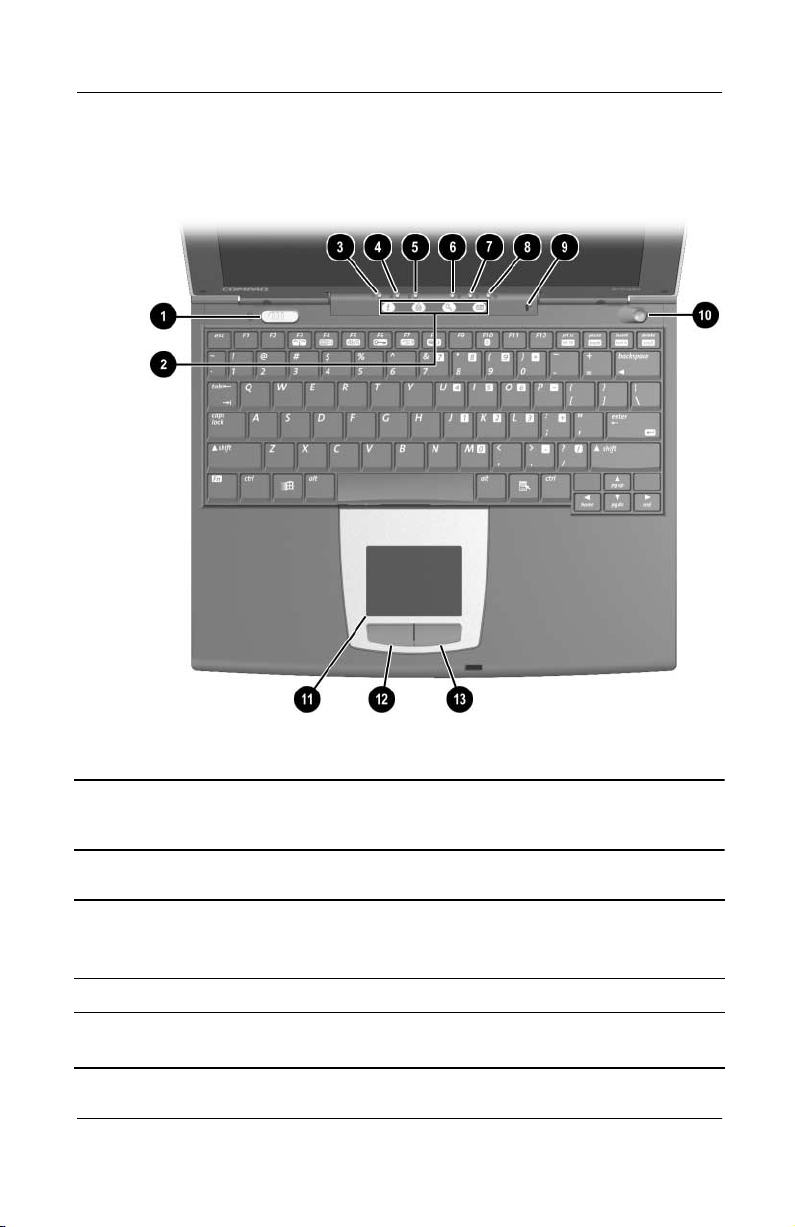
The external components on the top of the computer are shown in
Figure 1-5 and described in Table 1-4.
Figure 1-5. Top Components
Table 1-4
Top Components
Item Component Function
1 Power switch Turns on the computer. To turn off the
computer, use the operating system Shut
Down command.
2 Easy Access buttons (4) Provide quick access to the Internet.
3 Num lock light On: Num lock is on and the embedded
numeric keypad is enabled.
1–12 Maintenance and Service Guide
Page 18

Product Description
Table 1-4
Top Components
Item Component Function
4 Caps lock light On: Caps lock is on.
5 Scroll lock light On: Scroll lock is on.
6 Battery light On: A battery pack is charging. Blinking: A
7 Hard drive light On: The primary hard drive is being
8 Power light On: Power is turned on.
(Continued)
battery pack that is the only available
power source has reached a low-battery
condition.
accessed.
Blinking: Computer is in Standby.
The power light also blinks if a
✎
battery pack that is the only
available power source reaches
a critical low-battery condition
while Hibernation is disabled.
9 Microphone Inputs single-channel sound to the
computer; can be used whether the
computer is open or closed.
10 Standby button
11 TouchPad Moves the mouse cursor, selects, and
12 Left TouchPad button Functions like the left mouse button on an
13 Right TouchPad button Functions like the right mouse button on
■
Turns on the computer if it is off.
■
Initiates and exits Standby.
■
When pressed with the Fn key,
initiates Hibernation.
activates.
external mouse.
an external mouse.
Maintenance and Service Guide 1–13
Page 19
Product Description
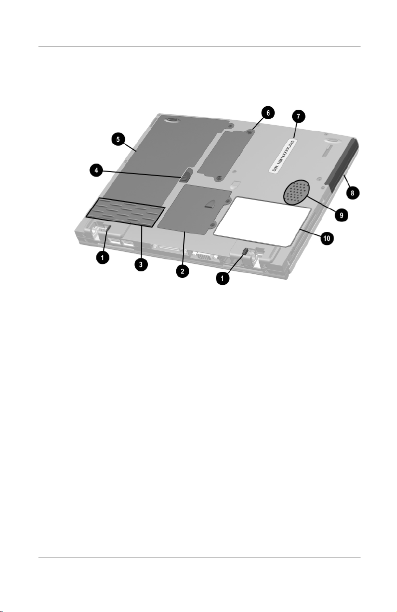
The external components on the bottom of the computer are
shown in Figure 1-6 and described in Table 1-5.
fm
Figure 1-6. Bottom Components
1–14 Maintenance and Service Guide
Page 20

Table 1-5
Bottom Components
Item Component Function
Product Description
1 External battery release
latches (2)
2 Mini PCI compartment cover Contains the mini PCI modem or
3 Vents Provides airflow to cool internal
4 Primary battery release latch Releases the primary battery pack
5 Battery bay Holds the primary battery pack.
6 Memory expansion
compartment cover
7 Serial number Identifies the computer; needed
8 Hard drive Supports the removable primary
9 Speaker Produces sound.
10 Certificate of Authenticity label Contains the Product Key, which
Release the external battery pack.
network interface card.
components.
from the battery bay.
Covers the memory expansion
compartment that contains one
memory expansion slot for a memory expansion board.
when you call Compaq customer
support.
hard drive. One screw secures the
hard drive to the computer.
may need to be entered before
using some Windows operating
systems.
Maintenance and Service Guide 1–15
Page 21

Product Description
1.4 Design Overview
This section presents a design overview of key parts and features
of the computer. Refer to Chapter 3, “Illustrated Parts Catalog,” to
identify replacement parts, and Chapter 5, “Removal and
Replacement Procedures,” for disassembly steps.
The system board provides the following device connections:
Memory expansion board
■
Hard drive
■
Display
■
Keyboard
■
TouchPa d
■
Audio
■
Intel Pentium III processor
■
PC Card
■
Modem
■
Network interface card
■
CAUTION: To properly ventilate the computer, allow at least a 3-inch
Ä
(7.6 cm) clearance on the right side of the computer.
1–16 Maintenance and Service Guide
Page 22

Troubleshooting
WARNING: Only authorized technicians trained by Compaq should
Å
repair this equipment. All troubleshooting and repair procedures
are detailed to allow only subassembly/module level repair.
Because of the complexity of the individual boards and
subassemblies, no one should attempt to make repairs at the
component level or to make modifications to any printed wiring
board. Improper repairs can create a safety hazard. Any indication
of component replacement or printed wiring board modification may
void any warranty or exchange allowances.
Utilities that are preinstalled on the computer include:
PhoenixBIOS Setup Utility—Allows you to modify or
■
restore factory default settings and configure the system
BIOS to diagnose and solve minor problems.
Power Management—Allows you to reduce your computer
■
power consumption.
2
Security—Allows you to set or remove your power-on
■
password.
Using the PhoenixBIOS Setup Utility
The PhoenixBIOS Setup Utility (PSU) is built into the system.
You can configure the system BIOS and modify or restore factory
default settings, such as date and time, types of disk drives, power
management, and password settings. To run PSU, press the
key during system startup. When the main screen displays, use
the keyboard and arrow keys to move around the menus and make
selections.
Maintenance and Service Guide 2–1
F10
Page 23

Troubleshooting
Troubleshooting Flowcharts
Table 2-1
Troubleshooting Flowcharts Overview
Section Description
2.1 Initial troubleshooting
2.2 No power, part 1
2.3 No power, part 2
2.4 No power, part 3
2.5 No power, part 4
2.6 No video, part 1
2.7 No video, part 2
2.8 Nonfunctioning docking station
2.9 No operating system (OS) loading
2.10 No OS loading from hard drive, part 1
2.11 No OS loading from hard drive, part 2
2.12 No OS loading from hard drive, part 3
2.13 No OS loading from diskette drive
2.14 No OS loading from CD- or DVD-ROM drive
2.15 No audio, part 1
2.16 No audio, part 2
2.17 Nonfunctioning device
2.18 Nonfunctioning keyboard
2.19 Nonfunctioning pointing device
2.20 No network or modem connection
2–2 Maintenance and Service Guide
Page 24
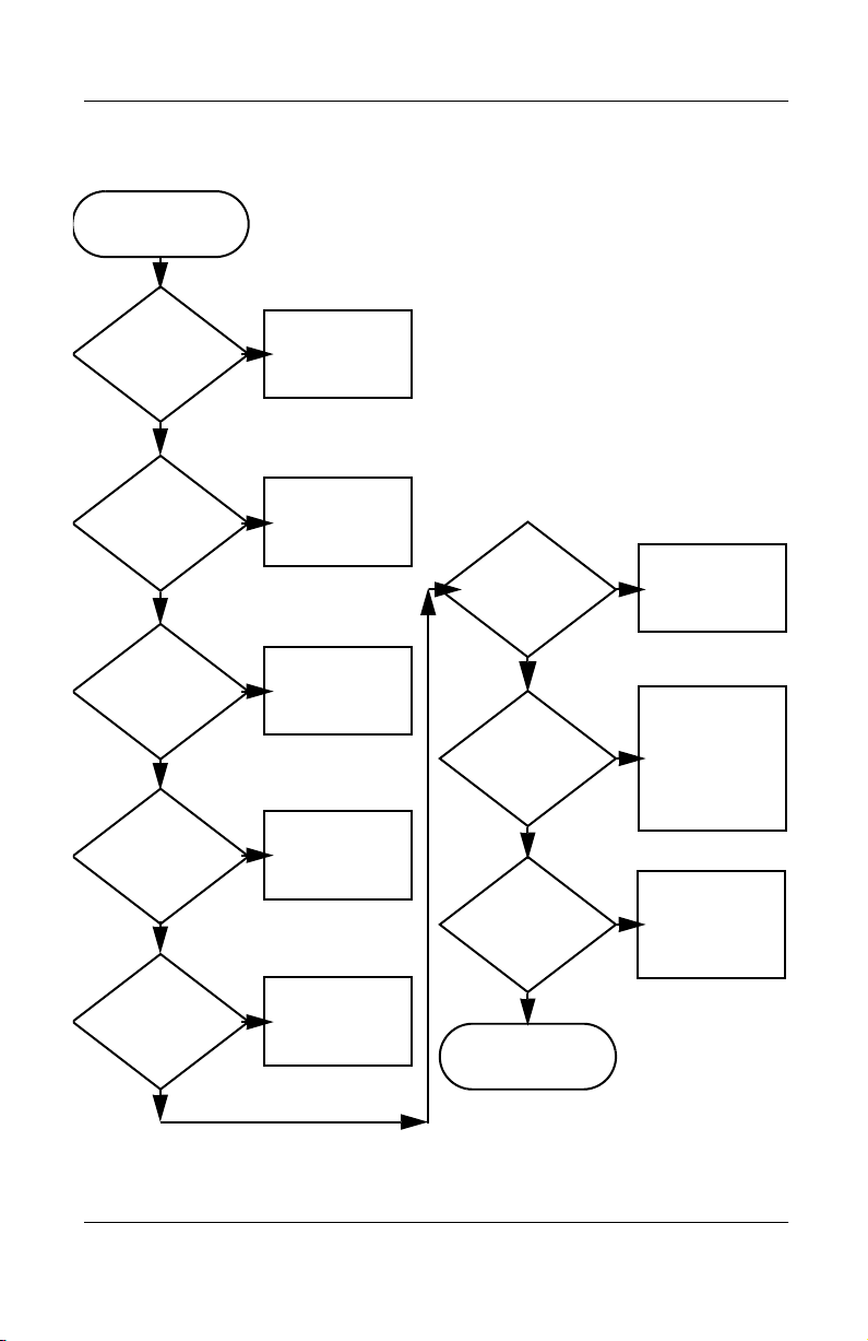
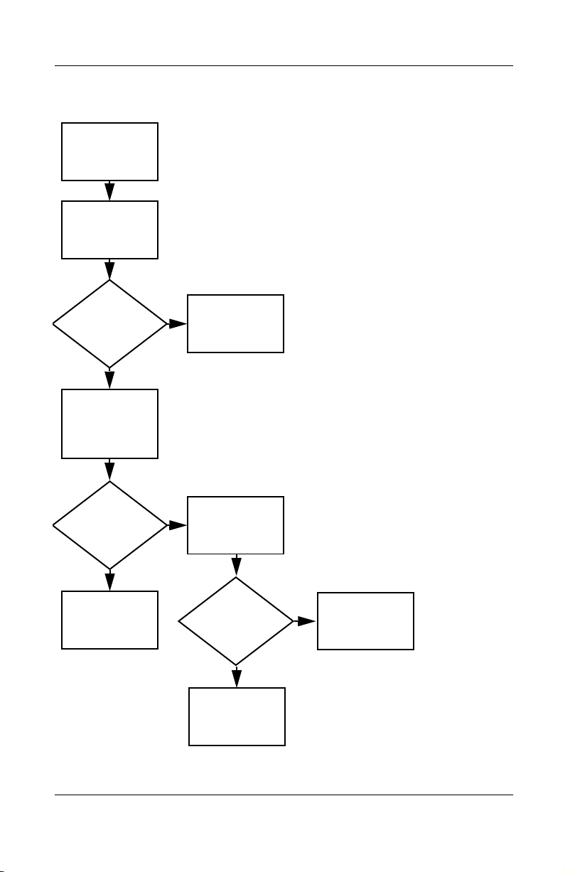
Initial Troubleshooting
Begin
Troubleshooting
N
Is there
power?
Y
N
Beeps,
LEDs, or error
Messages?
Y
N
Is there video?
(no boot)
Y
N
Is the OS
loading?
Y
N
Is there
sound?
Y
Go to
Section 2.2,
No Power.
Check
LED board,
speaker
connections.
Go to
Section 2.6,
No Video.
Go to
Section 2.9,
No OS Loading.
Go to
Section 2.15,
No Audio.
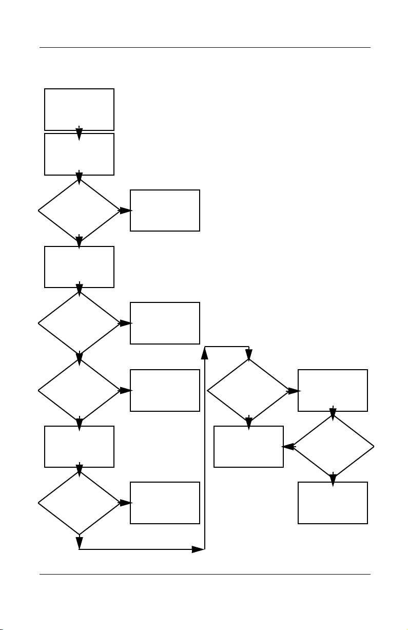
Y
Y
Connecting
or modem?
Y
All drives
working?
Keyboard/
pointing
device
working?
to network
End
Troubleshooting
N
Section 2.17,
Nonfunctioning
N
Section 2.18,
Nonfunctioning
or Section 2.19,
Nonfunctioning
Pointing Device.
N
Section 2.20,
Go to
Device.
Go to
Keyboard,
Go to
No Network
or Modem
Connection.
Maintenance and Service Guide 2–3
Page 25
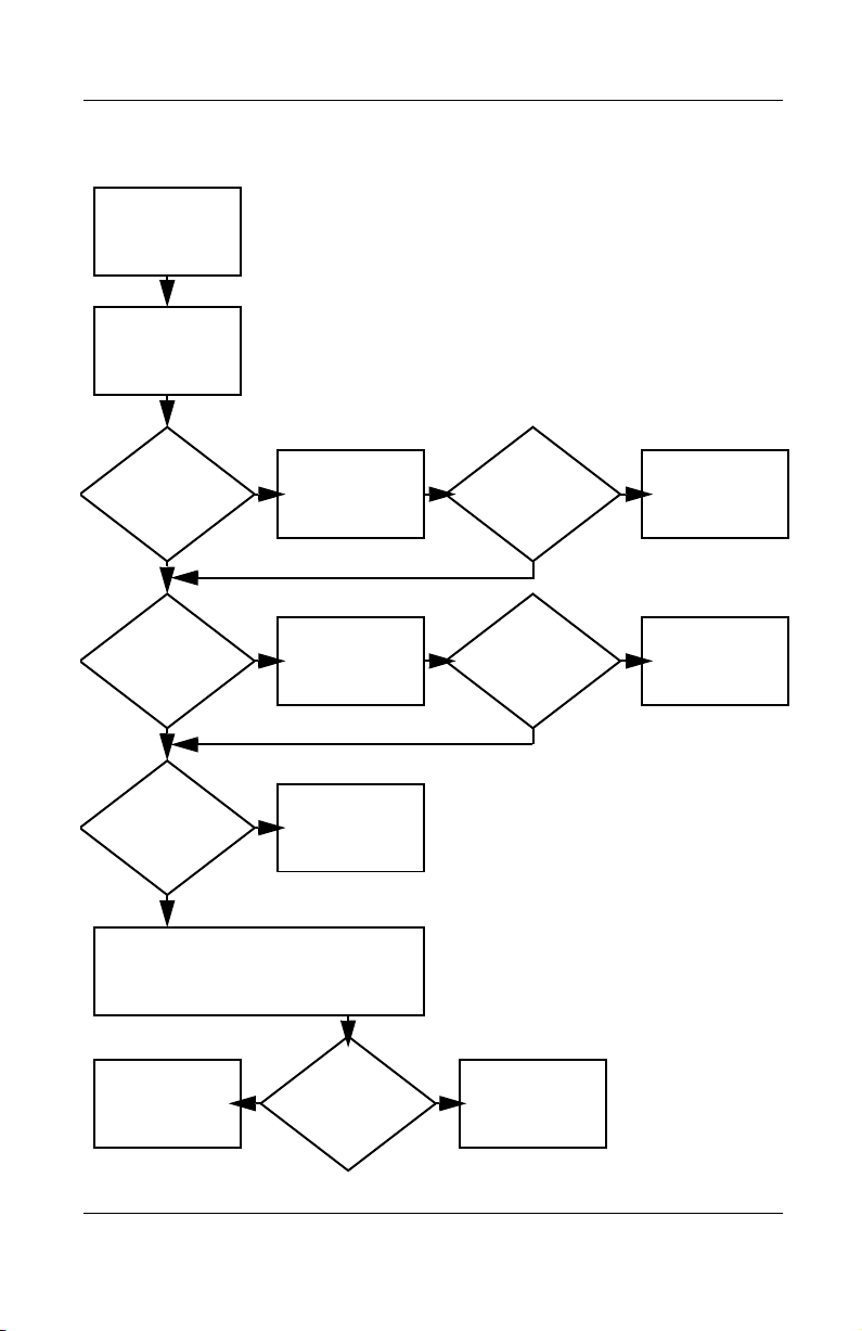
Troubleshooting
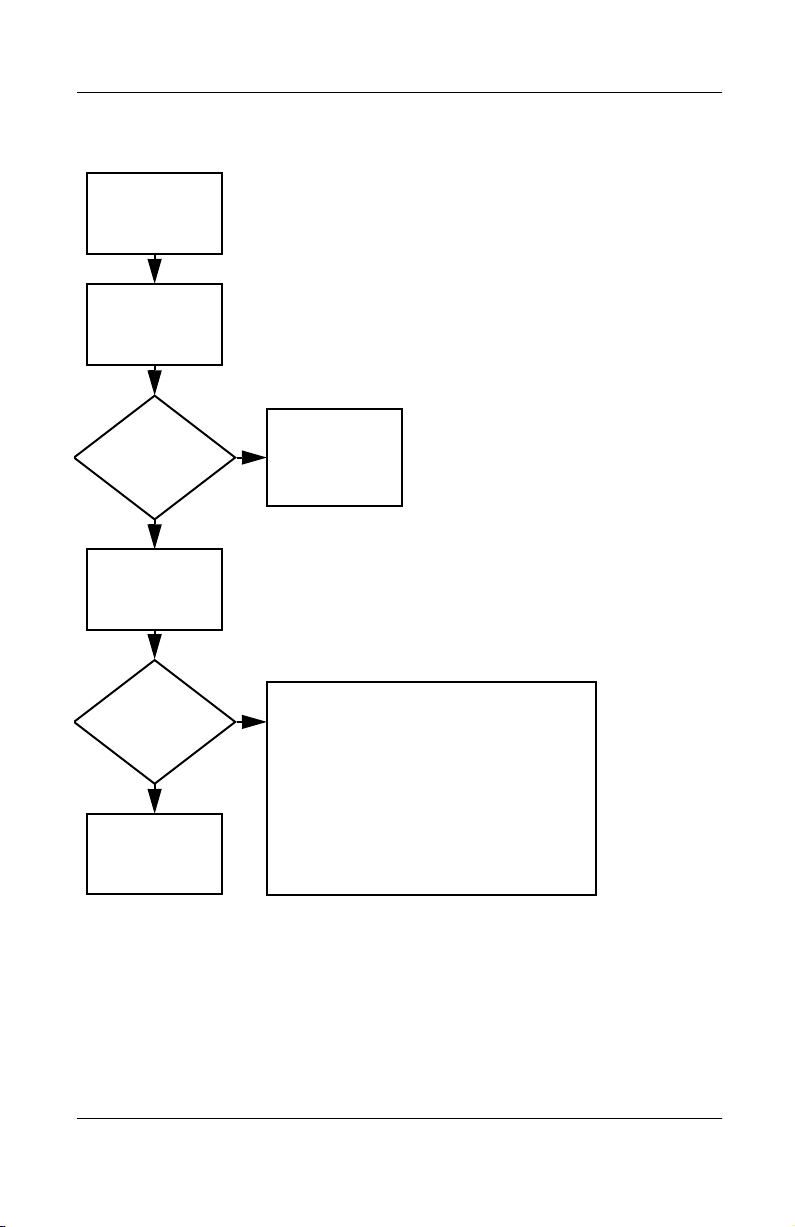
2.2 No Power, Part 1
No Power
(Power LED is off)
Remove from
docking station
if applicable.
N
Power up
on battery
power?
*Reset
power.
Y
N
Power up
on AC
power?
*Reset
power.
Y
Y
Power up
in docking
station?
Done
N
1. Reseat power cables in docking station
and at the AC outlet.
2. Ensure the AC power source is active.
3. Ensure the power strip is working.
YN
Done
Power up
in docking
station?
N
Power up
on battery
power?
Go to
Section 2.3,
No Power,
Part 2.
Y
N
Power up
on AC
power?
Go to
Section 2.4,
No Power,
Part 3.
Y
*Notes:
1. On some models, there is a separate reset
button.
2. On some models, the computer may be
reset using the Standby switch and either
the lid switch or the main power switch.
Go to
Section 2.8,
Nonfunctioning
Docking Station.
2–4 Maintenance and Service Guide
Page 26
2.3 No Power, Part 2
Continued from
Section 2.2,
No Power, Part 1.
Visually check for
debris in battery
socket and clean
if necessary.
Y
Troubleshooting
Power on?
N
Check battery by
recharging,
moving it to
another computer,
or replacing it.
Power on?
Y
Done
Done
N
Replace power
supply (if
applicable).
N
Go to
Power on?
Section 2.4,
No Power,
Part 3.
Y
Done
Maintenance and Service Guide 2–5
Page 27
Troubleshooting
2.4 No Power, Part 3
Continued from
Section 2.3,
No Power, Part 2.
Plug directly
into AC outlet.
Y
Power LED
on?
N
Reseat AC adapter
in computer and
at power source.
Power on?
N
Power outlet
active?
Y
Replace
power cord.
Power on?
Done
Y
Done
N
Try different
outlet.
Internal or
external AC
Internal
Section 2.5,
No Power,
Y
Done Done
adapter?
Go to
Part 4.
External
Replace external
AC adapter.
N
Power on?
Y
N
2–6 Maintenance and Service Guide
Page 28
2.5 No Power, Part 4
Continued from
Section 2.4,
No Power, Part 3.
Open
computer.
Troubleshooting
Loose or
damaged
parts?
N
Close
computer and
retest.
Power on?
Y
Done
Y
Reseat loose
components and
boards and
replace
damaged items.
N
Replace the following items, if applicable.
Check computer operation after each
replacement:
1. Internal DC-DC converter*
2. Internal AC adapter
3. Processor board*
4. System board*
*Replace these items as a set to prevent
shorting out among components.
Maintenance and Service Guide 2–7
Page 29
Troubleshooting
2.6 No Video, Part 1
No Video
Docking
Station
Stand-alone
or Docking
Station?
Go to
Section 2.7,
No Video, Part 2.
*Note: To change from internal to
external display, use the hotkey
combination.
Standalone
Y
Internal or
external
display*?
External
Adjust
brightness.
Internal
Y
Video OK? Done
N
Check for bent
pins on cable.
Adjust
brightness.
Video OK? Done
N
A
Depress lid
switch to ensure
operation.
Y
Video OK? Done
N
Replace the following one at a time. Test after each replacement:
1. Cable between notebook and computer display (if applicable)
2. Inverter board (if applicable)
3. Display
4. System board
NN
Video OK?
Try
another
display.
Internal and
external
video OK?
Replace
system
board.
YY
Done
2–8 Maintenance and Service Guide
Done
Page 30

Troubleshooting
Page 31

Troubleshooting
2.8 Nonfunctioning Docking Station
(if applicable)
Nonfunctioning
docking station
Reseat power
cord in docking
station and
power outlet.
Check voltage
setting on
docking station.
Reset monitor
cable connector at
docking station.
Docking
station
operating?
N
Remove
notebook, reseat
all internal parts,
and replace any
damaged items in
docking station.
Reinstall
notebook into
docking station.
Y
Docking
station
operating?
Done
N
Y
Done
Replace these docking station components
one at a time. Check computer operation
after each replacement:
1. Power supply
2. I/O board
3. Backplane board
4. Switch box
5. Docking motor mechanism
2–10 Maintenance and Service Guide
Page 32

2.9 No Operating System (OS) Loading
No OS
loading
Reseat power
cord in docking
station and
power outlet.
No OS loading
from hard drive,
go to
Section 2.10.
No OS loading
form diskette
drive, go to
Section 2.13.
No OS loading
from CD- or
DVD-ROM drive,
go to
Section 2.14.
Troubleshooting
No OS loading
from network,
go to
Section 2.20.
*Note: Before beginning, always check
cable connections, cable ends, and drives
for bent or damaged pins.
Maintenance and Service Guide 2–11
Page 33

Troubleshooting
2.10 No OS Loading from Hard Drive, Part 1
OS not
loading from
hard drive.
Nonsystem
disk message?
N
Reseat
external
hard drive.
OS loading?
N
Boot
from
CD?
Y
Check the setup
utility for correct
booting order.
Y
Go to
Section 2.11,
No OS Loading
from Hard Drive,
Part 2.
Y
Done
N
N
Boot
from
diskette?
Y
Go to
Section 2.13,
No OS
Loading from
Diskette Drive.
N
Boot
from
hard drive?
Y
Done
Change boot
priority through
the setup utility
and reboot.
Boot
from
hard drive?
N
Go to
Section 2.17,
Nonfunctioning
Device.
Y
2–12 Maintenance and Service Guide
Page 34

Troubleshooting
2.11 No OS Loading from Hard Drive, Part 2
Continued from
Section 2.10,
No OS Loading
from Hard Drive,
Part 1.
CD or
diskette in
drive?
Y
Remove
diskette and
reboot.
N
1. Replace hard
drive.
2. Replace system
board.
Reseat
hard drive.
Y
Hard drive
accessible?
N
Run FDISK.
Done
Boot
from
hard drive?
N
Boot
from diskette
drive?
Y
Hard drive
accessible?
Y
Go to
Section 2.12,
No OS Loading
from Hard Drive,
Part 3.
Y
N
No OS Loading
N
Done
Go to
Section 2.13,
from Diskette
Drive.
Done
Hard drive
partitioned?
Y
Hard drive
formatted?
Y
Y
Computer
booted?
Go to
Section 2.12,
No OS Loading
from Hard Drive,
Part 3.
N
Create partition,
then format hard
drive to bootable
C:\ prompt.
N
Format hard drive
and bring to a
bootable C:\
prompt.
Load OS using
Restore CD if
N
applicable.
Maintenance and Service Guide 2–13
Page 35

Troubleshooting
2.12 No OS Loading from Hard Drive, Part 3
Continued from
Section 2.11,
No OS Loading
from Hard Drive,
Part 2.
N
System
files on hard
drive?
Y
Install OS
and reboot.
Virus
on hard
drive?
N
Run SCANDISK
and check for
bad sectors.
Can bad
sectors
be fixed?
Y
Fix bad
sectors.
Y
Clean virus.
OS
loading from
hard drive?
Y
Done
N
Y
Diagnostics
on diskette?
Replace
hard drive.
N
N
Replace
hard drive.
Run diagnostics
and follow
recommendations.
N
Boot from
hard drive?
Replace
hard drive.
Y
Done
2–14 Maintenance and Service Guide
Page 36

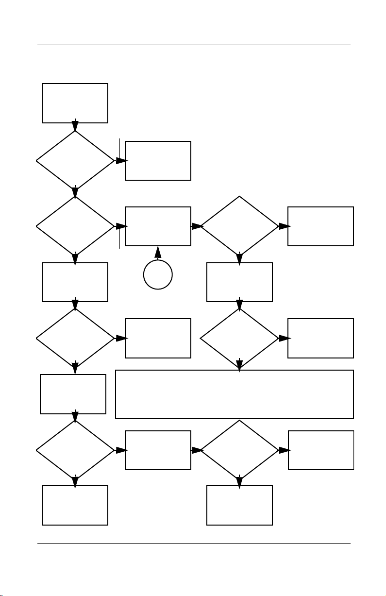
2.13 No OS Loading from Diskette Drive
Y
Troubleshooting
OS not loading
from
diskette drive.
Nonsystem
disk message?
Boot
from another
device?
Y
Diskette
drive enabled
in the setup
utility?
Y
Y
N
N
Reseat
diskette drive.
Go to
Section 2.17,
Nonfunctioning
Device.
Enable drive
and cold boot
computer.
OS
loading?
N
Bootable
diskette
in drive?
YN
Check diskette
for system files.
Try different
diskette.
Nonsystem
disk error?
N
Done
N
Install bootable
diskette and
reboot computer.
Y
1. Replace
diskette drive.
2. Replace system
board.
Y
Clear CMOS.
Diskette
drive boot
order?
Change boot
priority using
the setup utility.
Maintenance and Service Guide 2–15
Refer to Section
1.2, “Clearing a
Password,” for
instructions.
Go to
Section 2.17,
Nonfunctioning
Device
OS
loading?
NN
Y
Done
Page 37

Troubleshooting
Y
N
2.14 No OS Loading from CD- or
DVD-ROM Drive
No OS
loading from
CD- or
DVD-ROM drive.
Boots from
CD or DVD?
N
Reseat
drive.
N
Y
N
Y
Disk
in drive?
Install
bootable disk.
Done
Boots from
CD or DVD?
Booting
from another
device?
Y
Y
N
Bootable
disk in
drive?
Try another
bootable
disk.
Done
Go to
Section 2.17,
Nonfunctioning
Device.
Install bootable
disk and
reboot
computer.
Y
Booting
order
correct?
N
Correct boot
order using
the setup utility.
2–16 Maintenance and Service Guide
Clear CMOS.
Refer to Section
1.2, “Clearing a
Password,” for
instructions.
Go to
Section 2.17,
Nonfunctioning
Device.
Page 38

2.15 No Audio, Part 1
Y
Turn up audio
No audio
internally or
externally.
Troubleshooting
Audio? Done
N
Notebook in
docking station
(if applicable)?
N
Go to
Section 2.16,
No Audio, Part 2.
Y
Undock
Replace the following docking station
components one at a time as applicable.
Check after each change:
1. Reseat docking station audio cable.
2. Replace audio cable.
3. Replace speaker.
4. Replace docking station audio board.
5. Replace backplane board.
Go to
Section 2.17,
Nonfunctioning
Device
N
Internal
audio?
Y
Y
Audio? Done
N
Go to
Section 2.16,
No Audio, Part 2.
Maintenance and Service Guide 2–17
Page 39

Troubleshooting
2.16 No Audio, Part 2
Continued from
Section 2.15,
No Audio, Part 1
N
Audio
driver in OS
configured?
Y
N
Correct
drivers for
application?
Y
Connect to
external
speaker.
Reload
audio drivers.
Load drivers and
set configuration
in OS.
Replace audio
board and
Audio?
YN
2–18 Maintenance and Service Guide
speaker
connections in
notebook, if
applicable.
1. Replace internal speakers.
2. Replace audio board, if applicable.
3. Replace system board.
Audio? Done
YN
Page 40

2.17 Nonfunctioning Device
Nonfunctioning
device
Reseat
device.
Unplug the nonfunctioning device
from the notebook, inspect cables and
plugs for bent or broken pins or other
Clear
CMOS.
damage.
Any
physical
device?
N
Troubleshooting
Y
Fix or
replace
broken item.
Reattach device.
Close notebook,
plug in power,
and reboot.
N
Device
boots
properly?
Y
Done
Maintenance and Service Guide 2–19
Possible bad hard
drive. Replace
drive.
Possible bad NIC.
Replace card. If
integrated NIC,
replace system
board.
Possible bad
diskette drive.
Replace drive.
Go to
Section 2.9,
No OS Loading.
Device
boots
properly?
Y
Done
N
Page 41

Troubleshooting
2.18 Nonfunctioning Keyboard
Keyboard
not operating
properly.
Connect notebook
to good external
keyboard.
N
External
device
works?
Y
Reseat internal
keyboard
connector (if
applicable).
Replace
system
board.
N
OK?
Replace internal
keyboard or
cable.
Y
Y
Done Done
OK?
N
Replace
system
board.
2–20 Maintenance and Service Guide
Page 42

2.19 Nonfunctioning Pointing Device
Pointing device
not operating
properly.
Connect notebook
to good external
pointing device.
N
External
device
works?
Y
Reseat internal
pointing device
connector (if
applicable).
Replace
system
board.
Troubleshooting
N
Replace internal
OK?
pointing device or
cable.
Y
Y
Done Done
OK?
N
Replace
system
board.
Maintenance and Service Guide 2–21
Page 43

Troubleshooting
2.20 Network or Modem Connection Problems
No network
or modem
connection.
N
Network
or modem jack
active?
Y
Digital
line?
N
NIC/modem
configured in OS?
Replace jack or
Y
to non-digital
N
drivers and
reconfigure.
have jack
activated.
Connect
line.
Reload
OK?
Y
Done
Y
Disconnect all
power from
the notebook
and open.
N
Replace
NIC/modem if
applicable.
Y
Reseat
NIC/modem if
applicable.
OK? Done
N
Replace
system
board.
2–22 Maintenance and Service Guide
Page 44

Illustrated Parts Catalog
This chapter provides an illustrated parts breakdown and a
reference for spare part numbers and option part numbers.
3.1 Serial Number Location
When ordering parts or requesting information, provide the
computer serial number and model number located on the bottom
of the computer as indicated in Figure 3-1.
3
Figure 3-1. Serial Number Location
Maintenance and Service Guide 3–1
Page 45

Illustrated Parts Catalog
3.2 Computer System Major Components
Figure 3-2. Computer System Major Components
3–2 Maintenance and Service Guide
Page 46

Illustrated Parts Catalog
Tabl e 3-1
Computer System Major Components
Spare Part
Item Description
1 10.4-inch XGA TFT Display 251633-001
Miscellaneous Plastics Kit 251638-001
Number
2a
2b
2c
2d
2e
Left hinge cover
Right hinge cover
LED cover
Memory expansion
compartment cover
Mini PCI compartment cover
Not illustrated
■
Computer feet (4)
■
PC Card slot weight saver
■
External battery slot
spacers
Cable Kit 251639-001
3a
3b
Microphone
LED board cable
Not illustrated
■
Modem/NIC cable
■
Audio cable
■
TouchPad cable
4 LED board 251631-001
5 Keyboards
Belgian
Brazilian
Czech
Danish
French
French
Canadian
German
Hebrew
Hungarian
International
Italian
Japanese
246339-181
246339-201
246339-221
246339-081
246339-051
246339-121
246339-041
246339-BB1
246339-211
246339-002
246339-061
246339-291
Korean
Latin American
Spanish
Norwegian
Portuguese
Russian
Spanish
Swedish
Swiss
Taiwanese
Tu r ki s h
U.K. English
U.S. English
246339-AD1
246339-161
246339-091
246339-131
246339-251
246339-071
246339-101
246339-111
246339-AB1
246339-141
246339-031
246339-001
Maintenance and Service Guide 3–3
Page 47

Illustrated Parts Catalog
Computer System Major Components (continued)
3–4 Maintenance and Service Guide
Page 48

Illustrated Parts Catalog
Tabl e 3-1
Computer System Major Components
Item Description
6 Top Cover (includes TouchPad) 251643-001
(Continued)
Spare Part
Number
7 System board with 700-MHz Intel Pentium III
processor and 64 MB SDRAM
128-MB memory expansion board (shipped on
system board; not illustrated)
8 RTC battery 252443-001
9 Combination modem/network interface card (NIC) 233558-001
10 Charger board 251640-001
11 Base enclosure (includes speaker and left and right
external battery terminals and cables)
12 Hard drives
20-GB hard drive
Optional 30-GB hard drive
13 Battery packs
6-cell Lithium ion primary battery pack
Optional 4-cell Lithium ion external battery pack
251642-001
254086-001
251634-001
251635-001
251636-001
240284-001
240285-001
Maintenance and Service Guide 3–5
Page 49

Illustrated Parts Catalog
3.3 Miscellaneous Plastics Kit
Components
Figure 3-3. Miscellaneous Plastics Kit Components
Table 3-2
Miscellaneous Plastics Kit Components
Spare Part Number 251638-001
Item Description Item Description
1 Left hinge cover (2) 5 Mini PCI compartment cover
2 Right hinge cover (2) 6 Computer feet (4)
3 LED cover 7 PC Card weight saver
4 Memory expansion
compartment cover
3–6 Maintenance and Service Guide
8 External battery slot
spacers (2)
Page 50

Removal and Replacement Procedures
2. Remove the LED cover (Section 5.6).
3. Remove the microphone (Section 5.7).
4. Remove the keyboard (Section 5.8).
5. Release the ZIF connector
to which the LED board cable is
1
connected and disconnect the LED board cable
(Figure 5-8).
6. Remove the two black TM2 × 4 screws
LED board to the top cover.
7. Remove the LED board
4
.
2
that secure the
3
Figure 5-8. Removing the LED Board
Maintenance and Service Guide 5–13
Page 51

Removal and Replacement Procedures
The LED board cable is included in the Cable Kit (spare part
✎
number 251639-001).
To remove the LED board cable from the system board:
1. Release the ZIF connector
connected and disconnect the LED board cable
(Figure 5-9).
2. Remove the LED board cable
Figure 5-9. Removing the LED Board Cable
Reverse the above procedure to install the LED board and LED
board cable.
to which the LED board cable is
1
2
.
3
5–14 Maintenance and Service Guide
Page 52

Removal and Replacement Procedures
5.10 Display
When the display screws are removed, the assembly is
✎
unsupported. Make sure to provide support for the display when
removing the display screws.
Display
Spare Part Number Information
10.4-inch XGA TFT display 251633-001
1. Prepare the computer for disassembly (Section 5.3) and
remove the following components:
a. LED cover (Section 5.6)
b. Microphone (Section 5.7)
c. Keyboard (Section 5.8)
d. LED board and cable (Section 5.9)
Maintenance and Service Guide 5–15
Page 53

Removal and Replacement Procedures
2. Slide the left and right hinge covers away from the
computer
The hinge covers are included in the Miscellaneous Plastics Kit
✎
(spare part number 251638-001).
(Figure 5-10).
1
3. Disconnect the display inverter
the system board.
4. Remove the two silver TM2 × 15 screws
TM2 × 5 screws
base enclosure.
Figure 5-10. Removing the Display
5. Remove the display.
that secure the display to the top cover and
5
and video cables 3 from
2
and the two black
4
5–16 Maintenance and Service Guide
Page 54

Removal and Replacement Procedures
To ensure proper alignment of the display during replacement,
✎
loosely install the screws in the
Figure 5-11. Tighten the screws after all four have been been
loosely installed.
1, 2, 3, 4
sequence indicated in
Figure 5-11. Installing the Display Screws
Maintenance and Service Guide 5–17
Page 55

Removal and Replacement Procedures
5.11 Top Cover
Top C over
Spare Part Number Information
Top cover 251643-001
1. Prepare the computer for disassembly (Section 5.3) and
remove the following components:
a. LED cover (Section 5.6)
b. Microphone (Section 5.7)
c. Keyboard (Section 5.8)
d. LED board and cable (Section 5.9)
e. Display (Section 5.10)
2. Turn the computer bottom side up with the front facing you.
5–18 Maintenance and Service Guide
Page 56

Removal and Replacement Procedures
3. Remove the six pewter TM2 × 8 screws (Figure 5-12).
Figure 5-12. Removing the Top Cover Screws
4. Turn the computer top side up with the rear panel facing you.
Maintenance and Service Guide 5–19
Page 57

Removal and Replacement Procedures
5. Remove the following screws:
two pewter TM2 × 8 screws 1 that secure the top cover
❏
to the base enclosure (Figure 5-13)
two black TM2 × 4 screws 2 from the rear panel
❏
two 5.0 mm screwlocks 3 on each side of the external
❏
monitor connector
6. Use a 9/64” hex wrench to remove the two bushing guides
on each side of the docking connector.
Figure 5-13. Removing the Top Cover Screws (Continued)
4
5–20 Maintenance and Service Guide
Page 58

Removal and Replacement Procedures
7. Lift up the back edge of the top cover 1 until the TouchPad
cable
prevents it from lifting any farther (Figure 5-14).
2
8. Release the ZIF connector
connected and disconnect the TouchPad cable
The LED board cable is included in the Cable Kit (spare part
✎
number 251639-001).
Figure 5-14. Removing the Top Cover
9. Remove the top cover.
to which the TouchPad cable is
3
4
.
Reverse the above procedure to install the top cover.
Maintenance and Service Guide 5–21
Page 59

Removal and Replacement Procedures
5.12 RTC Battery
RTC Battery
Spare Part Number Information
RTC battery 252443-001
1. Prepare the computer for disassembly (Section 5.3) and
remove the following components:
a. LED cover (Section 5.6)
b. Microphone (Section 5.7)
c. Keyboard (Section 5.8)
d. LED board and cable (Section 5.9)
e. Display (Section 5.10)
f. Top cover (Section 5.11)
5–22 Maintenance and Service Guide
Page 60

Removal and Replacement Procedures
2. Disconnect the RTC battery cable from the system board 1
(Figure 5-15).
3. Remove the RTC battery from the slot in the base
enclosure
2
.
Figure 5-15. Removing the Real Time Clock Battery
4. Remove the RTC Battery.
Reverse the above procedure to install the RTC Battery.
Maintenance and Service Guide 5–23
Page 61

Removal and Replacement Procedures
5.13 System Board
System Board
Spare Part Number Information
System board with 700-MHz Intel Pentium III processor and
64 MB SDRAM
1. Prepare the computer for disassembly (Section 5.3) and
remove the following components:
a. LED cover (Section 5.6)
b. Microphone (Section 5.7)
c. Keyboard (Section 5.8)
d. LED board and cable (Section 5.9)
e. Display (Section 5.10)
f. Top cover (Section 5.11)
g. RTC battery (Section 5.12)
251642-001
5–24 Maintenance and Service Guide
Page 62

Removal and Replacement Procedures
2. Disconnect the left 1 and right 2 external battery terminal
cables and the speaker cable
Figure 5-16. Disconnecting the Battery Terminal and
Speaker Cables
(Figure 5-16).
3
Maintenance and Service Guide 5–25
Page 63

Removal and Replacement Procedures
3. Lift up the right side of the system board 1 until it rests at a
45-degree angle.
4. Slide the system board to the right at a 45-degree angle
(Figure 5-17).
Figure 5-17. Removing the System Board
Reverse the above procedure to install the system board.
2
5–26 Maintenance and Service Guide
Page 64

Removal and Replacement Procedures
5.14 Charger Board
Charger Board
Spare Part Number Information
Charger board 251640-001
1. Prepare the computer for disassembly (Section 5.3) and
remove the following components:
a. LED cover (Section 5.6)
b. Microphone (Section 5.7)
c. Keyboard (Section 5.8)
d. LED board and cable (Section 5.9)
e. Display (Section 5.10)
f. Top cover (Section 5.11)
g. RTC battery (Section 5.12)
h. System board (Section 5.13)
2. Turn the system board top side up with the front facing you.
Maintenance and Service Guide 5–27
Page 65

Removal and Replacement Procedures
3. Remove the two silver PM1x6 screws 1 that secure the
charger board to the system board (Figure 5-18).
4. Turn the system board top side up with the stereo speaker and
headphone jacks facing you.
5. Lift up on the left front side
board to disconnect it from the system board.
Figure 5-18. Removing the Charger Board
CAUTION: Do not lift the charger board by the right side 4. The
Ä
material on the right side of the board is thinner and more prone to
damage. Failure to follow this caution can result in damage to the
charger board and the computer.
and center 3 of the charger
2
6. Remove the charger board.
Reverse the above procedure to install the charger board.
5–28 Maintenance and Service Guide
Page 66

5.15 Modem/NIC Cable
The modem/NIC cable is included in the Cable Kit (spare part
✎
number 251639-001).
1. Prepare the computer for disassembly (Section 5.3) and
remove the following components:
a. LED cover (Section 5.6)
b. Microphone (Section 5.7)
c. Keyboard (Section 5.8)
d. LED board and cable (Section 5.9)
e. Display (Section 5.10)
f. Top cover (Section 5.11)
g. RTC battery (Section 5.12)
h. System board (Section 5.13)
Removal and Replacement Procedures
2. Turn the system board bottom side up with the rear panel
facing you.
Maintenance and Service Guide 5–29
Page 67

Removal and Replacement Procedures
3. Disconnect the modem/NIC cable from the system board1
(Figure 5-19).
4. Remove the modem/NIC cable
When installing the modem/NIC cable, route the cable between
✎
the docking connector 3 and the mini PCI connector 4.
Figure 5-19. Removing the Modem/NIC Cable
Reverse the above procedure to install the modem/NIC cable.
2
.
5–30 Maintenance and Service Guide
Page 68

5.16 Audio Cable
The audio cable is included in the Cable Kit (spare part number
✎
251639-001).
1. Prepare the computer for disassembly (Section 5.3) and
remove the following components:
a. LED cover (Section 5.6)
b. Microphone (Section 5.7)
c. Keyboard (Section 5.8)
d. LED board and cable (Section 5.9)
e. Display (Section 5.10)
f. Top cover (Section 5.11)
g. RTC battery (Section 5.12)
h. System board (Section 5.13)
Removal and Replacement Procedures
2. Turn the system board bottom side up with the front
facing you.
Maintenance and Service Guide 5–31
Page 69

Removal and Replacement Procedures
3. Disconnect both connectors on the audio cable 1 from the
system board (Figure 5-20).
4. Remove the audio cable
Figure 5-20. Removing the Audio Cable
2
.
Reverse the above procedure to install the audio cable.
5–32 Maintenance and Service Guide
Page 70

Specifications
This chapter provides physical and performance specifications.
Tabl e 6-1
Computer
Dimensions
Height
Width
Depth
Weight 3.5 lb 1.59 kg
Standalone (battery) power requirements
Nominal operating
voltage (Li ion)
Maximum operating
power
Peak operating power
.89 in
10.5 in
9.5 in
14.8 VDC
40 W
50 W
22 mm
266 mm
242 mm
6
AC adapter power requirements
Rated input power
Rated input current
Rated frequency
Tem pe rature
Operating
Nonoperating
Maintenance and Service Guide 6–1
90 to 264 VAC RMS (auto switching)
< 60 W
47 to 63 Hz
50 to 95°F
-4 to 140°F
10 to 35°C
-20 to 60°C
Page 71

Specifications
Relative humidity
Tabl e 6-1
Computer
(Continued)
Operating
Nonoperating
Altitude (unpressurized)
Operating
(14.7 to 10.1 psia)
Nonoperating
(14.7 to14.4 psia)
Shock
Operating
Nonoperating
Vibration
Operating
Nonoperating
Applicable product safety standards specify thermal limits for
✎
plastic surfaces. The computer operates well within this range of
temperatures.
10 to 90% relative humidity, non-condensing
5 to 90% relative humidity, 101.6°F/38.7°C
maximum wet bulb temperature
0 to 10,000 ft
0 to 30,000 ft
10 G, 11 ms, half sine
60 G, 11 ms, half sine
0.5 G, 10 to 500 Hz, 0.5 oct/min sweep rate
1.0 G, 10 to 500 Hz, 0.50 oct/min sweep rate
0 to 3,048 m
0 to 9,144 m
6–2 Maintenance and Service Guide
Page 72

Dimensions
Specifications
Tabl e 6-2
10.4-inch XGA, TFT Display
Height
Width
Diagonal
Number of colors Up to 16.8 million
Contrast ratio 125:1
Brightness 130 nits typical on AC power, 70 nits typical on
Pixel resolution
Pitch
Format
Configuration
Backlight Cold cathode fluorescent, 1 tube
Character display 80 × 25
Refresh rate 60 Hz
Total power
consumption
6.4 in
8.2 in
10.1 in
battery power, 115 nits minimum
1024 × 768
RGB vertical stripe
4 W
162 mm
209 mm
264 mm
0.264 × 0.264 mm
Maintenance and Service Guide 6–3
Page 73

Specifications
Table 6-3
Hard Drives
20.0 GB 10.0 GB
User capacity per drive
1
Drive height (with drive frame) 0.38 in, 9.5 mm 0.38 in, 9.5 mm
Drive width (with drive frame) 2.50 in, 70 mm 2.50 in, 70 mm
Interface type ATA - 5 ATA - 4
Seek times (typical read, including setting)
20.0 GB 10.0 GB
Single track
Average
Full stroke
User addressable sectors
Logical configuration
Cylinders
Heads
Sectors per track
2.5 ms
12.0 ms
23.0 ms
3
39,070,080 19,640,880
16,383
16
63
2.5 ms
12.0 ms
23.0 ms
16,383
16
63
6–4 Maintenance and Service Guide
Page 74

Specifications
Table 6-3
Hard Drives
Physical configuration
Cylinders
Heads
Sectors per track
Bytes per sector
Buffer size
Disk rotational speed 4200 rpm 4200 rpm
Transfer rate
Interface max (MB/s)
Media (Mb/s)
1
1 GB = 1,000,000,000 bytes.
2
System capability may differ.
3
Actual drive specifications may differ slightly.
Certain restrictions and exclusions apply. Consult the Compaq Customer Support Center for details.
3
3
3
2
3
(Continued)
20.0 GB 10.0 GB
22,784
4
293–560
512
2 MB 512KB
66.6
109–203
22,784
2
293–560
512
66.6
109–203
Maintenance and Service Guide 6–5
Page 75

Specifications
Dimensions
Primary Lithium ion (Li ion)
Height
Width
Depth
Weight
Cells
External Li ion
Height
Width
Depth
Weight
Cells
External Li ion High Capacity
Height
Width
Depth
Weight
Cells
Energy
Table 6-4
Battery Packs
.78 in
9.06 in
1.84 in
.49 lb
4
.9 in
10.47 in
.9 in
.48 lb
4
1.8 in
10.6 in
1.2 in
.93 lb
4
20 mm
231 mm
47 mm
.22 kg
23 mm
266 mm
23 mm
.22 kg
46 mm
269 mm
30 mm
.42 kg
Primary and External Li ion
Volt age
Amp-hour capacity
Watt-hour capacity
External Li ion High Capacity
Volt age
Amp-hour capacity
Watt-hour capacity
Environmental requirements
Temperature
Operating
Nonoperating
14.4 V
1.96 Ah
28 Wh
14.4 V
2.87 Ah
349 Wh
41°F to 95°F
-4°F to 140°F
5°C to 35°C
-20°C to 60°C
6–6 Maintenance and Service Guide
Page 76

Table 6-5
AC Adapter
Weight 0.39 lb .18 kg
Power supply (input)
Operating voltage
Operating current
Operating frequency range
Maximum transient
90 to 260 VAC RMS Nominal
1.3 A RMS
47 to 63 Hz Nominal
4/50 kV
Tabl e 6-6
System DMA
Hardware DMA System Function
DMA0 Available for audio
DMA1 Entertainment audio
(default; alternate = DMA0, DMA3, none)
Specifications
DMA2 Diskette drive
DMA3 ECP parallel port LPT1
(default; alternate = DMA0, none)
DMA4 DMA controller cascading (not available)
DMA5 Available for PC Card
DMA6 Not assigned
DMA7 Not assigned
PC Card controller can use DMA 1, 2, or 5.
✎
Maintenance and Service Guide 6–7
Page 77

Specifications
Tabl e 6-7
System Interrupts
Hardware IRQ System Function
IRQ0 System timer
IRQ1 Keyboard controller
IRQ2 Cascaded
IRQ3 COM2
IRQ4 COM1
IRQ5 Audio (default)*
IRQ6 Diskette drive
IRQ7 Parallel port
IRQ8 Real time clock (RTC)
IRQ9 Infrared
IRQ10 System use
IRQ11 System use
IRQ12 Internal point stick or external mouse
IRQ13 Coprocessor (not available to any peripheral)
IRQ14 IDE interface (hard drive and optical drive)
IRQ15 System use
PC Cards may assert IRQ3, IRQ4, IRQ5, IRQ7, IRQ9, IRQ10, IRQ11,
✎
or IRQ15. Either the infrared or the serial port may assert IRQ3 or
IRQ 4.
*Default configuration; audio possible configurations are IRQ5, IRQ7, IRQ9,
IRQ10, or none.
6–8 Maintenance and Service Guide
Page 78

Tabl e 6-8
System I/O Addresses
I/O Address (hex) System Function (shipping configuration)
000 - 00F DMA controller no. 1
010 - 01F Unused
020 - 021 Interrupt controller no. 1
022 - 024 Opti chipset configuration registers
025 - 03F Unused
02E - 02F 87334 “Super IO” configuration for CPU
040 - 05F Counter/timer registers
044 - 05f Unused
060 Keyboard controller
061 Port B
062 - 063 Unused
064 Keyboard controller
Specifications
065 - 06F Unused
070 - 071 NMI enable/real time clock
072 - 07F Unused
080 - 08F DMA page registers
090 - 091 Unused
092 Port A
093 - 09F Unused
0A0 - 0A1 Interrupt controller no. 2
Maintenance and Service Guide 6–9
Page 79

Specifications
Tabl e 6-8
System I/O Addresses
I/O Address (hex) System Function (shipping configuration)
0A2 - 0BF Unused
0C0 - 0DF DMA controller no. 2
0E0 - 0EF Unused
0F0 - 0F1 Coprocessor busy clear/reset
0F2 - 0FF Unused
100 - 16F Unused
170 - 177 Secondary fixed disk controller
178 - 1EF Unused
1F0 - 1F7 Primary fixed disk controller
1F8 - 200 Unused
201 Joystick (decoded in ESS1688)
202 - 21F Unused
(Continued)
220 - 22F Entertainment audio
230 - 26D Unused
26E - 26 Unused
278 - 27F Unused
280 - 2AB Unused
2A0 - 2A7 Unused
2A8 - 2E7 Unused
2E8 - 2EF Reserved serial port
6–10 Maintenance and Service Guide
Page 80

Tabl e 6-8
System I/O Addresses
I/O Address (hex) System Function (shipping configuration)
2F0 - 2F7 Unused
2F8 - 2FF Infrared port
300 - 31F Unused
320 - 36F Unused
370 - 377 Secondary diskette drive controller
378 - 37F Parallel port (LPT1/default)
380 - 387 Unused
388 - 38B FM synthesizer - OPL3
38C - 3AF Unused
3B0 - 3BB VGA
3BC - 3BF Reserved (parallel port/no EPP support)
3C0 - 3DF VGA
(Continued)
Specifications
3E0 - 3E1 PC Card controller in CPU
3E2 - 3E3 Unused
3E8 - 3EF Internal modem
3F0 - 3F7 “A” diskette controller
3F8 - 3FF Serial port (COM1/default)
CF8 - CFB PCI configuration index register (PCIDIVO-1)
CFC - CFF PCI configuration data register (PCIDIVO-1)
Maintenance and Service Guide 6–11
Page 81

Specifications
vt
Table 6-9
System Memory Map
Size Memory Address System Function
640 KB 00000000 - 0009FFFF Base memory
128 KB 000A0000 - 000BFFFF Video memory
48 KB 000C0000 - 000CBFFF Video BIOS
160 KB 000C8000 - 000E7FFF Unused
64 KB 000E8000 - 000FFFFF System BIOS
15 MB 00100000 - 00FFFFFF Extended memory
58 MB 01000000 - 047FFFFF Super extended memory
58 MB 04800000 - 07FFFFFF Unused
2 MB 08000000 - 080FFFFF Video memory (direct access)
4 GB 08200000 - FFFEFFFF Unused
64 KB FFFF0000 - FFFFFFFF System BIOS
6–12 Maintenance and Service Guide
Page 82

Connector Pin Assignments
Tabl e A -1
Stereo Speaker/Headphone
Pin Signal Pin Signal
1 Audio out 2 Ground
A
Maintenance and Service Guide A–1
Page 83

Connector Pin Assignments
Tabl e A -2
Microphone
Pin Signal Pin Signal
1 Audio in 2 Ground
Tabl e A -3
Universal Serial Bus
Pin Signal Pin Signal
1 +5 VDC 3 Data +
2 Data - 4 Ground
A–2 Maintenance and Service Guide
Page 84

Connector Pin Assignments
Tabl e A -4
RJ-45 Network Interface
Pin Signal Pin Signal
1 Transmit + 5 Unused
2 Transmit - 6 Receive -
3 Receive + 7 Unused
4Unused 8Unused
Tabl e A -5
RJ-11 Modem
Pin Signal Pin Signal
1Unused 4Unused
2 Tip 5 Unused
3Ring 6Unused
Maintenance and Service Guide A–3
Page 85

Connector Pin Assignments
Tabl e A -6
External Monitor
Pin Signal Pin Signal
1 Red analog 9 +5 VDC
2 Green analog 10 Ground
3 Blue analog 11 Monitor detect
4 Not connected 12 DDC 2B data
5 Ground 13 Horizontal sync
6 Ground analog 14 Vertical sync
7 Ground analog 15 DDC2B clock
8 Ground analog
A–4 Maintenance and Service Guide
Page 86

Power Cord Set Requirements
3-Conductor Power Cord Set
The computer’s wide range input feature permits it to operate
from any line voltage from 100 to 120 or 220 to 240 volts AC.
The power cord set received with the computer meets the
requirements for use in the country where the equipment is
purchased.
Power cord sets for use in other countries must meet the
requirements of the country where the computer is used. For more
information on power cord set requirements, contact a Compaq
authorized reseller or service provider.
General Requirements
The requirements listed below are applicable to all countries:
The length of the power cord set must be at least 5.00 feet
■
(1.5 m) and a maximum of 6.50 feet (2.0 m).
B
All power cord sets must be approved by an acceptable
■
accredited agency responsible for evaluation in the country
where the power cord set will be used.
The power cord set must have a minimum current capacity of
■
10A and a nominal voltage rating of 125 or 250 volts AC, as
required by each country’s power system.
The appliance coupler must meet the mechanical
■
configuration of an EN 60 320/IEC 320 Standard Sheet C13
connector, for mating with appliance inlet on the back of the
computer.
Maintenance and Service Guide B–1
Page 87

Power Cord Set Requirements
Country-Specific Requirements
3-Conductor Power Cord Set Requirements—By Country
Country Accredited Agency Applicable Note Number
Australia EANSW 1
Austria OVE 1
Belgium CEBC 1
Canada CSA 2
Denmark DEMKO 1
Finland FIMKO 1
France UTE 1
Germany VDE 1
Italy IMQ 1
Japan METI 3
The Netherlands KEMA 1
Norway NEMKO 1
Sweden SEMKO 1
Switzerland SEV 1
United Kingdom BSI 1
United States UL 2
B–2 Maintenance and Service Guide
Page 88

Notes
Power Cord Set Requirements
1. The flexible cord must be <HAR> Type HO5VV-F,
3-conductor, 1.0mm2 conductor size. Power cord set fittings
(appliance coupler and wall plug) must bear the certification
mark of the agency responsible for evaluation in the country
where it will be used.
2. The flexible cord must be Type SPT-3 or equivalent, No. 18
AWG, 3-conductor. The wall plug must be a two-pole
grounding type with a NEMA 5-15P (15A, 125V) or NEMA
6-15P (15A, 250V) configuration.
3. The appliance coupler, flexible cord, and wall plug must bear
a “T” mark and registration number in accordance with the
Japanese Dentori Law. The flexible cord must be Type VCT
2
or VCTF, 3-conductor, 1.0 mm
conductor size. The wall
plug must be a two-pole grounding type with a Japanese
Industrial Standard C8303 (7A, 125V) configuration.
Maintenance and Service Guide B–3
Page 89

C
Screw Listing
This appendix provides specification information for the screws
used in the computer. All screws listed in this appendix are
available in the Screw Kit, spare part number 251641-001.
Maintenance and Service Guide C–1
Page 90

Tabl e C-1
Phillips PO M2 × 10 Screw
Color Qty Length Thread
Black 1 10.0 mm M2 4.5 mm
Where used:
One screw securing the battery pack to the base enclosure (refer to the
Hardware Guide
shipped with the computer for installation information.)
Head
Width
C–2 Maintenance and Service Guide
Page 91

Tabl e C-2
Torx T8 M2.5 × 5 Screw
Color Qty Length Thread
Black 1 5.0 mm M2.5 5.5 mm
Where used:
One screw securing the hard drive to the base enclosure (refer to the
Hardware Guide
shipped with the computer for installation information.)
Head
Width
Maintenance and Service Guide C–3
Page 92

Tabl e C-3
Phillips P0 M2 × 4 Screw
Head
Color Qty Length Thread
Black 4 4.0 mm M2.0 4.5 mm
Where used:
1 Two screws securing the memory expansion compartment cover to the base
enclosure (Refer to the
installation information.)
2 Two screws securing the mini PCI compartment cover to the base enclosure
(documented in Section 5.5)
Hardware Guide
shipped with the computer for
Width
C–4 Maintenance and Service Guide
Page 93

Tabl e C-4
Torx T 8 M2 × 4 S crew
Head
Color Qty Length Thread
Black 7 4.0 mm M2.0 4.5 mm
Where used:
1 Three screws securing the keyboard to the top cover and base enclosure
(documented in Section 5.8)
2 Two screws securing the LED board to the top cover (documented in
Section 5.9)
Width
Maintenance and Service Guide C–5
Page 94

Tabl e C-4
Torx T8 M2 × 4 Screw
Color Qty Length Thread
Black 7 4.0 mm M2.0 4.5 mm
Where used:
Two screws securing the top cover to the base enclosure (documented in
Section 5.11)
(Continued)
Head
Width
C–6 Maintenance and Service Guide
Page 95

Tabl e C-5
Torx T8 M2 × 15 Screw
Color Qty Length Thread
Silver 2 15.0 mm M2 4.5 mm
Where used:
Two screws securing the display the base enclosure (documented in
Section 5.10)
Head
Width
Maintenance and Service Guide C–7
Page 96

Tabl e C-6
Torx T8 M2 × 5 Screw
Head
Color Qty Length Thread
Black 2 5.0 mm M2 4.5 mm
Where used:
One screw securing the display the top cover (documented in Section 5.10)
Width
C–8 Maintenance and Service Guide
Page 97

Tabl e C-7
Torx T8 M2 × 8 Screw
Head
Color Qty Length Thread
Pewter 8 8.0 mm M2 4.5 mm
Where used:
Six screws securing the top cover to the base enclosure through the bottom of
the computer (documented in Section 5.11)
s
Width
Maintenance and Service Guide C–9
Page 98

Tabl e C-7
Torx T8 M2 × 8 Screw
Color Qty Length Thread
Pewter 8 8.0 mm M2 4.5 mm
Where used:
Two screws securing the top cover to the base enclosure through the top of the
computer (documented in Section 5.11)
(Continued)
Head
Width
C–10 Maintenance and Service Guide
Page 99

Tabl e C-8
5.0 mm × 9.5 Screwlock
Head
Color Qty Length Thread
Silver 2 9.5 mm n/a 5.0 mm
Where used:
Two screwlocks securing the top cover to the base enclosure on each side of
the external monitor connector (documented in Section 5.11)
Width
Maintenance and Service Guide C–11
Page 100

Tabl e C-9
9/64” Hex Wrench Bushing Guide
Head
Color Qty Length Thread
Silver 2 17.5 mm n/a 7.0 mm
Where used:
Two bushing guides securing the top cover to the base enclosure on each side
of the docking connector (documented in Section 5.11)
Width
C–12 Maintenance and Service Guide
 Loading...