

Page 1

b
Maintenance and Service Guide
Compaq Evo N115 Series
Document Part Number: 263816-001
January 2002
This guide is a troubleshooting reference used for maintaining
and servicing the notebook. It provides comprehensive
information on identifying computer features, components, and
spare parts, troubleshooting computer problems, and performing
computer disassembly procedures.
Page 2

© 2002 Compaq Information Technologies Group, L.P.
Compaq, the Compaq logo, and Evo are trademarks of Compaq Information
Technologies Group, L.P. in the U.S. and/or other countries.
Microsoft and Windows are trademarks of Microsoft Corporation in the U.S.
and/or other countries.
Athlon, Duron, and PowerNow! are trademarks of the AMD Corporation in the
U.S. and/or other countries.
All other product names mentioned herein may be trademarks of their respective
companies.
Compaq shall not be liable for technical or editorial errors or omissions
contained herein. The information in this document is provided “as is” without
warranty of any kind and is subject to change without notice. The warranties for
Compaq products are set forth in the express limited warranty statements
accompanying such products. Nothing herein should be construed as
constituting an additional warranty.
Maintenance and Service Guide
First Edition January 2002
Document Part Number: 263816-001
Page 3

Contents
1 Product Description
1.1 Models . . . . . . . . . . . . . . . . . . . . . . . . . . . . . . . . . . . . 1–2
1.2 Features . . . . . . . . . . . . . . . . . . . . . . . . . . . . . . . . . . . 1–8
1.3 Clearing a Password. . . . . . . . . . . . . . . . . . . . . . . . . . 1–9
1.4 Power Management . . . . . . . . . . . . . . . . . . . . . . . . . 1–10
1.5 Computer External Components . . . . . . . . . . . . . . . 1–11
1.6 Design Overview . . . . . . . . . . . . . . . . . . . . . . . . . . . 1–22
2 Troubleshooting
2.1 Using the PhoenixBIOS Setup Utility . . . . . . . . . . . . 2–1
2.2 Troubleshooting Flowcharts. . . . . . . . . . . . . . . . . . . . 2–2
3 Illustrated Parts Catalog
3.1 Serial Number Location . . . . . . . . . . . . . . . . . . . . . . . 3–1
3.2 Computer System Major Components. . . . . . . . . . . . 3–2
3.3 Plastics and Hardware Kit Components. . . . . . . . . . . 3–8
3.4 Cable Kit Components . . . . . . . . . . . . . . . . . . . . . . . . 3–9
3.5 Mass Storage Devices . . . . . . . . . . . . . . . . . . . . . . . 3–10
3.6 Miscellaneous. . . . . . . . . . . . . . . . . . . . . . . . . . . . . . 3–12
Maintenance and Service Guide iii
Page 4

4 Removal and Replacement Preliminaries
4.1 Tools Required. . . . . . . . . . . . . . . . . . . . . . . . . . . . . . 4–1
4.2 Service Considerations. . . . . . . . . . . . . . . . . . . . . . . . 4–2
Plastic Parts . . . . . . . . . . . . . . . . . . . . . . . . . . . . . . . . 4–2
Cables and Connectors . . . . . . . . . . . . . . . . . . . . . . . 4–2
4.3 Preventing Damage to Removable Drives . . . . . . . . . 4–3
4.4 Preventing Electrostatic Damage . . . . . . . . . . . . . . . . 4–4
4.5 Packaging and Transporting Precautions . . . . . . . . . . 4–4
4.6 Workstation Precautions . . . . . . . . . . . . . . . . . . . . . . 4–5
4.7 Grounding Equipment and Methods . . . . . . . . . . . . . 4–6
5 Removal and Replacement Procedures
5.1 Serial Number . . . . . . . . . . . . . . . . . . . . . . . . . . . . . . 5–2
5.2 Disassembly Sequence Chart . . . . . . . . . . . . . . . . . . . 5–3
5.3 Preparing the Computer for Disassembly . . . . . . . . . 5–4
5.4 Computer Feet . . . . . . . . . . . . . . . . . . . . . . . . . . . . . 5–11
5.5 Memory Expansion Board . . . . . . . . . . . . . . . . . . . . 5–11
5.6 Mini PCI Communications Board . . . . . . . . . . . . . . 5–13
5.7 Optical Drive . . . . . . . . . . . . . . . . . . . . . . . . . . . . . . 5–16
5.8 LED Cover . . . . . . . . . . . . . . . . . . . . . . . . . . . . . . . . 5–18
5.9 Keyboard . . . . . . . . . . . . . . . . . . . . . . . . . . . . . . . . . 5–20
5.10 Display . . . . . . . . . . . . . . . . . . . . . . . . . . . . . . . . . . 5–22
5.11 Heat Spreader . . . . . . . . . . . . . . . . . . . . . . . . . . . . . 5–28
5.12 Processor . . . . . . . . . . . . . . . . . . . . . . . . . . . . . . . . 5–34
5.13 Disk Cell RTC Battery. . . . . . . . . . . . . . . . . . . . . . 5–36
5.14 Top Cover. . . . . . . . . . . . . . . . . . . . . . . . . . . . . . . . 5–38
5.15 Diskette Drive . . . . . . . . . . . . . . . . . . . . . . . . . . . . 5–42
5.16 Charger Board . . . . . . . . . . . . . . . . . . . . . . . . . . . . 5–46
5.17 Left Side Panel . . . . . . . . . . . . . . . . . . . . . . . . . . . . 5–48
5.18 Right Side Panel. . . . . . . . . . . . . . . . . . . . . . . . . . . 5–50
5.19 Speaker Assembly . . . . . . . . . . . . . . . . . . . . . . . . . 5–52
5.20 Audio Board . . . . . . . . . . . . . . . . . . . . . . . . . . . . . . 5–54
5.21 Fan . . . . . . . . . . . . . . . . . . . . . . . . . . . . . . . . . . . . . 5–56
5.22 System Board . . . . . . . . . . . . . . . . . . . . . . . . . . . . . 5–58
iv Maintenance and Service Guide
Page 5

6 Specifications
A Connector Pin Assignments
B Power Cord Set Requirements
3-Conductor Power Cord Set . . . . . . . . . . . . . . . . . . . . . . B–1
General Requirements . . . . . . . . . . . . . . . . . . . . . . . . B–1
Country-Specific Requirements . . . . . . . . . . . . . . . . . . . . B–2
Notes . . . . . . . . . . . . . . . . . . . . . . . . . . . . . . . . . . . . . B–2
C Screw Listing
Index
Maintenance and Service Guide v
Page 6
1
Product Description
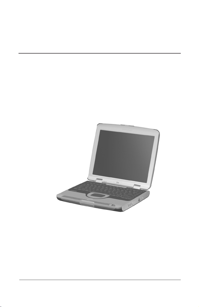
The Compaq Evo N115 Series of Personal Computers offers
advanced modularity, AMD Mobile Athlon 4 and AMD Mobile
Duron processors with 64-bit architecture, industry-leading
Accelerated Graphics Port (AGP) implementation, and extensive
multimedia support.
Figure 1-1. Compaq Evo N115
Maintenance and Service Guide 1–1
Page 7
Product Description
1.1 Models
Computer models are shown in Table 1-1.
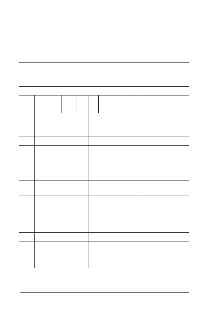
Table 1-1
Compaq Evo N115
Models and Model Naming Conventions
Key
N1 A 100 X4 20 V M 25 L O XXXXXX-XXX
123 45678910 11
Key Description Options
1 Brand/Series
designator
2 Processor type A = AMD Athlon D = AMD Duron
3 Processor speed 110 = 1.10 GHz
4 Display type/
size/resolution
5 Hard drive size 30 = 30 GB
6 Optical drive
designator
7 Integrated
communication
8 RAM 25 = 256 MB 12 = 128 MB
9 Battery cells/type L = 8 cells, Lithium ion (Li ion)
10 Operating system O = Windows XP
11 SKU#
N1 = Evo Notebook 115
900 = 900 MHz
100 = 1.00 GHz
950 = 950 MHz
X = XGA
(1024 × 768)
20 = 20 GB
D = CD-ROM
V = DVD-ROM
R = CD-RW
M = modem 0 = none
850 = 850 MHz
4 = 14.x-inch
3 = 13.x-inch
15 = 15 GB
10 = 10 GB
W = DVD-RW
omitted = none
1–2 Maintenance and Service Guide
Page 8
Product Description
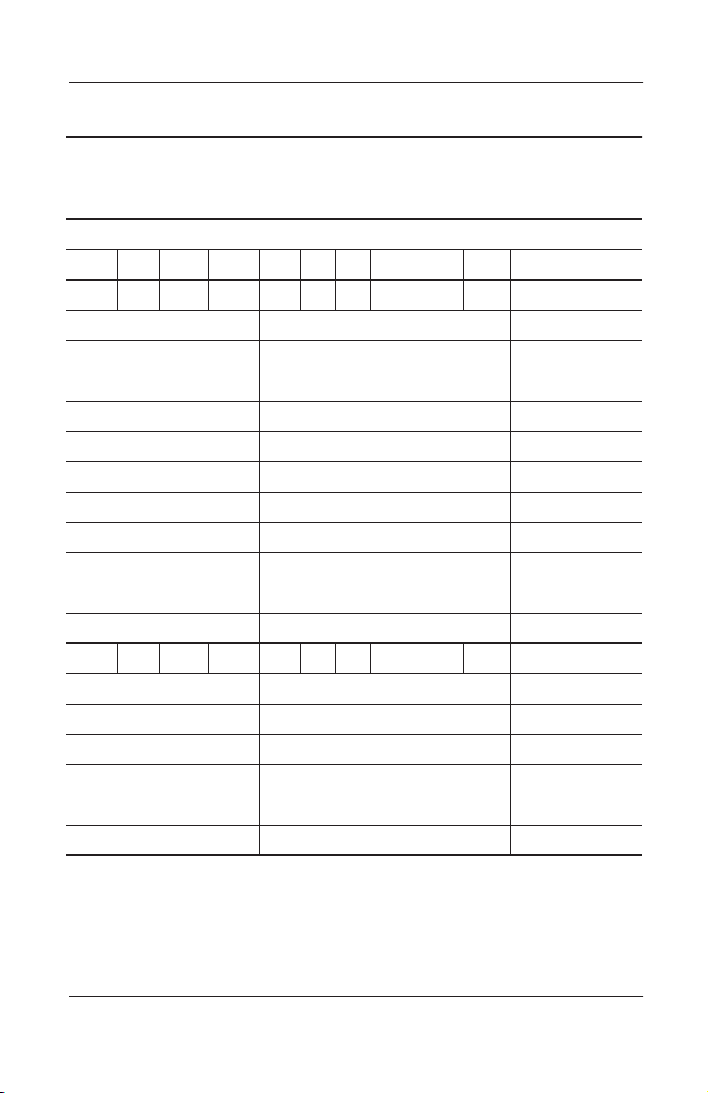
Table 1-1
Compaq Evo N115
Models and Model Naming Conventions
Build-to-Order Models
123 45678910 11
N1 A 100 X4 20 W M 25 L O SKU#
Belgium Config. code = KDH8 470023-558
Europe Config. code = KDH8 470020-516
France Config. code = KDH8 470020-518
Germany Config. code = KDH8 470020-520
Italy Config. code = KDH8 470020-522
The Netherlands Config. code = KDH8 470023-559
Poland Config. code = KDH8 470024-539
Switzerland Config. code = KDH8 470024-818
United Kingdom Config. code = KDH8 470023-560
United States Config. code = KDKU 470023-833
(Continued)
United States Config. code = KDKN 470023-551
N1 A 100 X4 20 V M 25 L O SKU#
Australia/New Zealand Config. code = KDKV 470020-462
Asia/Pacific Config. code = KDKV 470021-815
India Config. code = KDKV 470020-466
Portugal Config. code = KDH2 470024-541
Spain Config. code = KDH2 470024-542
Thailand Config. code = KDKV 470024-535
Maintenance and Service Guide 1–3
Page 9
Product Description
Models and Model Naming Conventions
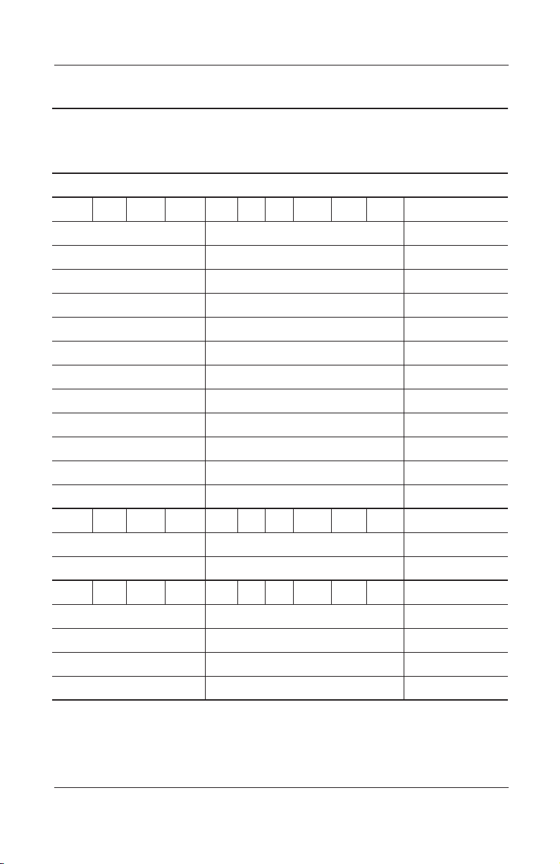
Table 1-1
Compaq Evo N115
(Continued)
Build-to-Order Models
N1 D 950 X4 20 V M 25 L O SKU#
Belgium Config. code = KDH7 470024-815
Denmark Config. code = KDH7 470024-536
Europe Config. code = KDH7 470023-930
Germany Config. code = KDH7 470025-650
Italy Config. code = KDH7 470023-570
Latin America Config. code = KDH3 470024-543
The Netherlands Config. code = KDH7 470024-816
Poland Config. code = KDH7 470024-538
Spain (NAFTA) Config. code = KDH3 470024-544
Sweden Config. code = KDH7 470024-817
Switzerland Config. code = KDH7 470023-576
United States Config. code = KDKM 470023-557
N1 D 950 X4 20 W M 12 L O SKU#
France Config. code = KJ21 470024-283
United Kingdom Config. code = KJ21 470024-540
N1 D 950 X4 20 D M 12 L O SKU#
Australia/New Zealand Config. code = KDH1 470023-555
(Continued)
Asia/Pacific Config. code = KDH1 470023-968
India Config. code = KDH1 470023-556
Thailand Config. code = KDH1 470024-534
1–4 Maintenance and Service Guide
Page 10
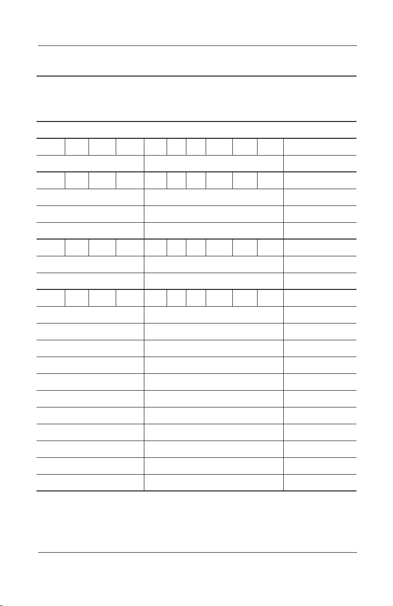
Table 1-1
Compaq Evo N115
Models and Model Naming Conventions
Product Description
(Continued)
Build-to-Order Models
N1 D 900 X4 20 W M 25 L O SKU#
Japan Config. code = KDJR 470023-566
N1 D 900 X4 20 V M 25 L O SKU#
Canada Config. code = KDHC 470020-491
French Canada Config. code = KDHC 470020-511
United States Config. code = KDHB 470020-490
N1 D 900 X4 20 V M 12 L O SKU#
France Config. code = KDKW 470024-749
United Kingdom Config. code = KDJR 470024-192
N1 D 900 X4 20 D M 12 L O SKU#
Denmark Config. code = KDJS 470020-473
Europe Config. code = KDJS 470020-474
Finland Config. code = KDJS 470020-475
Italy Config. code = KDJS 470020-479
Latin America Config. code = KDH9 470020-480
The Netherlands Config. code = KDJS 470020-488
Norway Config. code = KDJS 470020-481
Portugal Config. code = KDJS 470020-483
(Continued)
Spain Config. code = KDJS 470020-484
Spain (NAFTA) Config. code = KDH9 470020-489
Sweden Config. code = KDJS 470020-485
Maintenance and Service Guide 1–5
Page 11

Product Description
Models and Model Naming Conventions
Table 1-1
Compaq Evo N115
(Continued)
Build-to-Order Models
N1 D 900 X4 20 R M 25 L O SKU#
Japan Config. code = KDJP 470023-561
N1 D 900 X4 10 V M 12 L O SKU#
United States Config. code = KDH6 470024-820
Configure-to-Order Models
All configure-to-order models are United States models and have a
config. code of JNZZ.
N1 A 100 X4 20 V C 25 L O 470025-434
N1 A 100 X4 20 V C 25 L O 470024-822
N1 A 100 X4 20 V C 12 L O 470025-432
N1 A 100 X4 20 W C 25 L O 470025-429
N1 A 100 X4 20 W C 12 L O 470025-427
N1 A 100 X3 20 V C 25 L O 470025-433
N1 A 100 X3 20 V C 12 L O 470025-430
N1 A 100 X3 20 W C 25 L O 470025-428
N1 A 100 X3 20 W C 12 L O 470025-426
N1 D 950 X4 20 V C 25 L O 470025-444
(Continued)
N1 D 950 X4 20 V C 12 L O 470025-441
N1 D 950 X4 20 D C 25 L O 470025-438
N1 D 950 X4 20 D C 12 L O 470025-436
1–6 Maintenance and Service Guide
Page 12

Product Description
Table 1-1
Compaq Evo N115
Models and Model Naming Conventions
Configure-to-Order Models
All configure-to-order models are United States models and have a
config. code of JNZZ.
N1 D 950 X4 10 V C 25 L O 470025-425
N1 D 950 X4 10 V C 12 L O 470025-423
N1 D 950 X4 10 D C 25 L O 470025-420
N1 D 950 X4 10 D C 12 L O 470025-418
N1 D 950 X3 20 V C 25 L O 470025-442
N1 D 950 X3 20 V C 12 L O 470025-439
N1 D 950 X3 20 D C 25 L O 470025-437
N1 D 950 X3 20 D C 12 L O 470025-435
N1 D 950 X3 10 V C 25 L O 470025-424
N1 D 950 X3 10 V C 12 L O 470025-422
N1 D 950 X3 10 D C 25 L O 470025-419
(Continued)
N1 D 950 X3 10 D C 12 L O 470025-414
N1 D 950 X3 10 D C 12 L O 470025-415
N1 D 900 X4 15 D C 25 L O 470024-821
Maintenance and Service Guide 1–7
Page 13

Product Description
1.2 Features
1.1- or 1.0-GHz, or 950- or 900-MHz AMD Mobile Athlon 4
■
processor, with 256-KB integrated L2 cache, or 950-, 900-, or
850-MHz AMD Mobile Duron processor, with 64-KB
integrated L2 cache, varying by computer model
VIA ProSavage KN 133 graphics accelerator with up to
■
32-MB of shared SDRAM and 4X AGP graphics card
128-MB high-performance Synchronous DRAM (SDRAM),
■
expandable to 384 MB
Microsoft Windows XP Home or Professional, varying by
■
computer model
14.1- or 13.3-inch XGA, TFT (1024 × 768) display with over
■
16.7 million colors, varying by computer model
Full-size keyboard with TouchPad pointing device
■
Network interface card (NIC) integrated on the system board,
■
with a mini PCI V.92 modem
Support for one Type I/II/III PC Card slot with support for
■
both 32-bit CardBus and 16-bit PC Cards
External 60W AC adapter with power cord
■
8-cell Lithium ion (Li ion) battery pack
■
30-, 20-, 15-, or 10-GB high-capacity hard drive, varying by
■
computer model
1–8 Maintenance and Service Guide
Page 14

Connectors for:
■
RJ-45 network
❏
RJ-11 modem
❏
Universal Serial Bus
❏
S-Video
❏
Parallel devices
❏
External monitor
❏
AC power
❏
Stereo line out/headphone
❏
Mono microphone
❏
External keyboard/mouse
❏
JBL Pro stereo speakers with bass reflex
■
1.3 Clearing a Password
If the notebook you are servicing has an unknown password,
follow these steps to clear the password. These steps also
clear CMOS:
Product Description
1. Prepare the computer for disassembly (refer to Section 5.3,
“Preparing the Computer for Disassembly,” for more
information).
2. Remove the RTC battery (refer to Section 5.13, “Disk Cell
RTC Battery”).
3. Wait approximately five minutes.
4. Replace the RTC battery and reassemble the computer.
5. Connect AC power to the computer. Do not reinsert any
battery packs at this time.
6. Turn on the computer.
All passwords and all CMOS settings have been cleared.
Maintenance and Service Guide 1–9
Page 15

Product Description
1.4 Power Management
The computer comes with power management features that
extend battery operating time and conserve power. The computer
supports the following power management features:
Standby
■
Hibernation
■
Setting customization by the user
■
Hotkeys for setting level of performance
■
Smart battery that provides an accurate battery power gauge
■
Battery calibration
■
Lid switch suspend/resume
■
Power/suspend button
■
Advanced Configuration and Power Management (ACP)
■
compliance
1–10 Maintenance and Service Guide
Page 16
Product Description
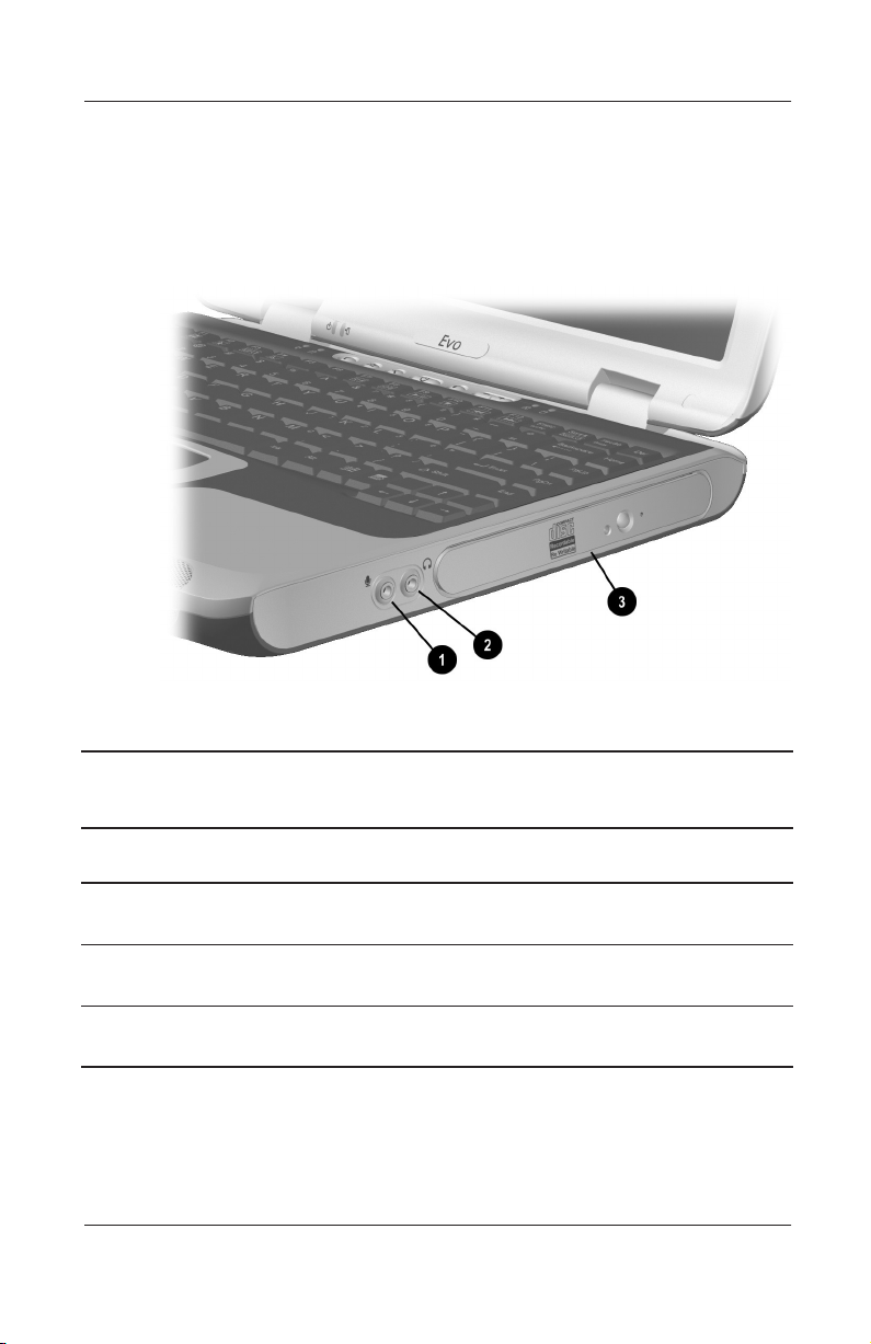
1.5 Computer External Components
The external components on the right side of the computer are
shown in Figure 1-2 and described in Table 1-2.
.
Figure 1-2. Right Side Components
Table 1-2
Right Side Components
Item Component Function
1 Mono microphone jack Connects a mono microphone, disabling the
built-in microphone.
2 Stereo speaker/
headphone jack
3 Optical drive Accepts a CD-ROM, CD-RW, DVD-ROM, or
Maintenance and Service Guide 1–11
Connects stereo speakers, headphones,
headset, or television audio.
combination DVD-ROM/CD-RW drive.
Page 17
Product Description
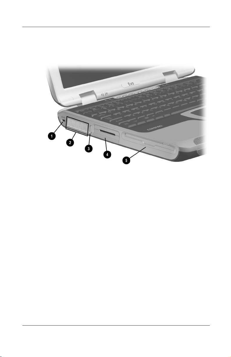
The computer left side components are shown in Figure 1-3 and
described in Table 1-3.
Figure 1-3. Left Side Components
1–12 Maintenance and Service Guide
Page 18

Product Description
Table 1-3
Left Side Components
Item Component Function
1 Security cable slot Attaches an optional security cable to the
computer.
2 Vents Allow airflow to cool internal components.
CAUTION: To prevent damage, the computer shuts down if an
Ä
overheating condition occurs. Do not block the cooling vent.
Avoid placing the computer on a blanket, rug, or other flexible
surface that may cover the vent area.
3 PC Card eject button Ejects a PC Card from the PC Card slot.
4 PC Card slot Supports a 32-bit (CardBus) or 16-bit
PC Card.
5 Diskette drive Accepts 3.5-inch diskettes.
Maintenance and Service Guide 1–13
Page 19
Product Description
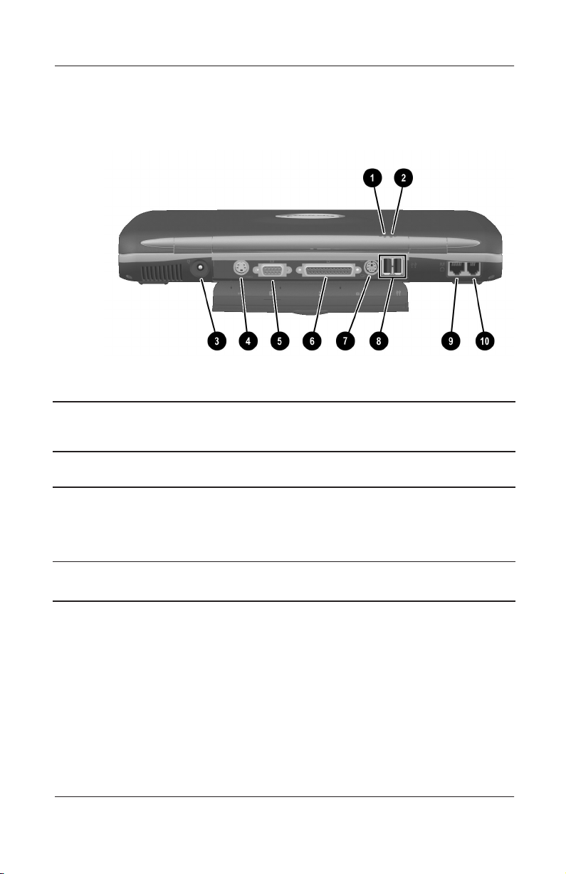
The computer rear panel components are shown in Figure 1-4 and
described in Table 1-4.
Figure 1-4. Rear Panel Components
Table 1-4
Rear Panel Components
Item Component Function
1 Battery light On: A battery pack is charging.
Blinking: A battery pack that is the only
available power source has reached a
low-battery condition.
2 Drive activity light Turns on when the hard drive, CD-, or
DVD-ROM drive is accessed.
1–14 Maintenance and Service Guide
Page 20

Product Description
Table 1-4
Rear Panel Components
Item Component Function
3 DC power jack Connects any one of the following:
AC adapter
■
Optional automobile power
■
adapter/charger
Optional aircraft power adapter
■
4 S-Video connector Connects a television, VCR, camcorder, or
overhead projector.
(Continued)
5 External monitor
connector
6 Parallel connector Connects a parallel device.
7 External keyboard/
mouse connector
8 USB connectors (2) Connects USB devices.
9 RJ-45 network jack Connects the network cable. A network
10 RJ-11 modem jack Connects the modem cable to an internal
Connects an external monitor or overhead
projector.
Connects an optional full-sized keyboard or
a mouse. Both external mouse and
computer pointing device are active. An
optional splitter/adapter allows both an
external keyboard and mouse to be used at
the same time.
cable is not included with the computer.
modem. A modem cable is included with
internal modem models.
Maintenance and Service Guide 1–15
Page 21
Product Description
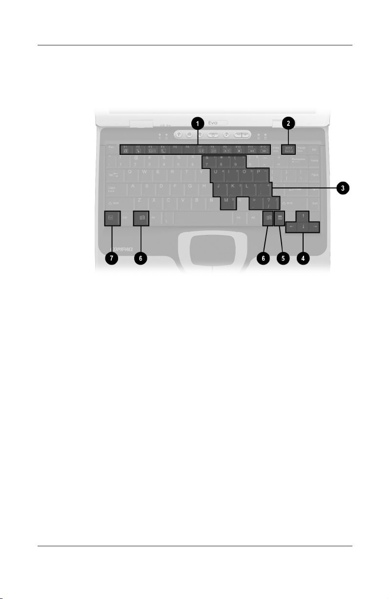
The keyboard components are shown in Figure 1-5 and described
in Table 1-5.
Figure 1-5. Keyboard Components
1–16 Maintenance and Service Guide
Page 22

Table 1 - 5
Keyboard Components
Item Component Function
Product Description
1
2 Num lock key Turns on the numeric lock function.
3 Embedded numeric
4 Cursor control keys Move the cursor around the screen.
5 Windows application
6 Windows logo keys Displays the Windows Start menu.
7
through
F1
function keys
keypad
key
key Used with hotkeys to perform preset hotkey
Fn
F12
Perform preset functions.
Converts keys to numeric keypad.
Displays a menu when using a Microsoft
application. The menu is the same one that
is displayed by pressing the right mouse
button.
functions.
Maintenance and Service Guide 1–17
Page 23
Product Description
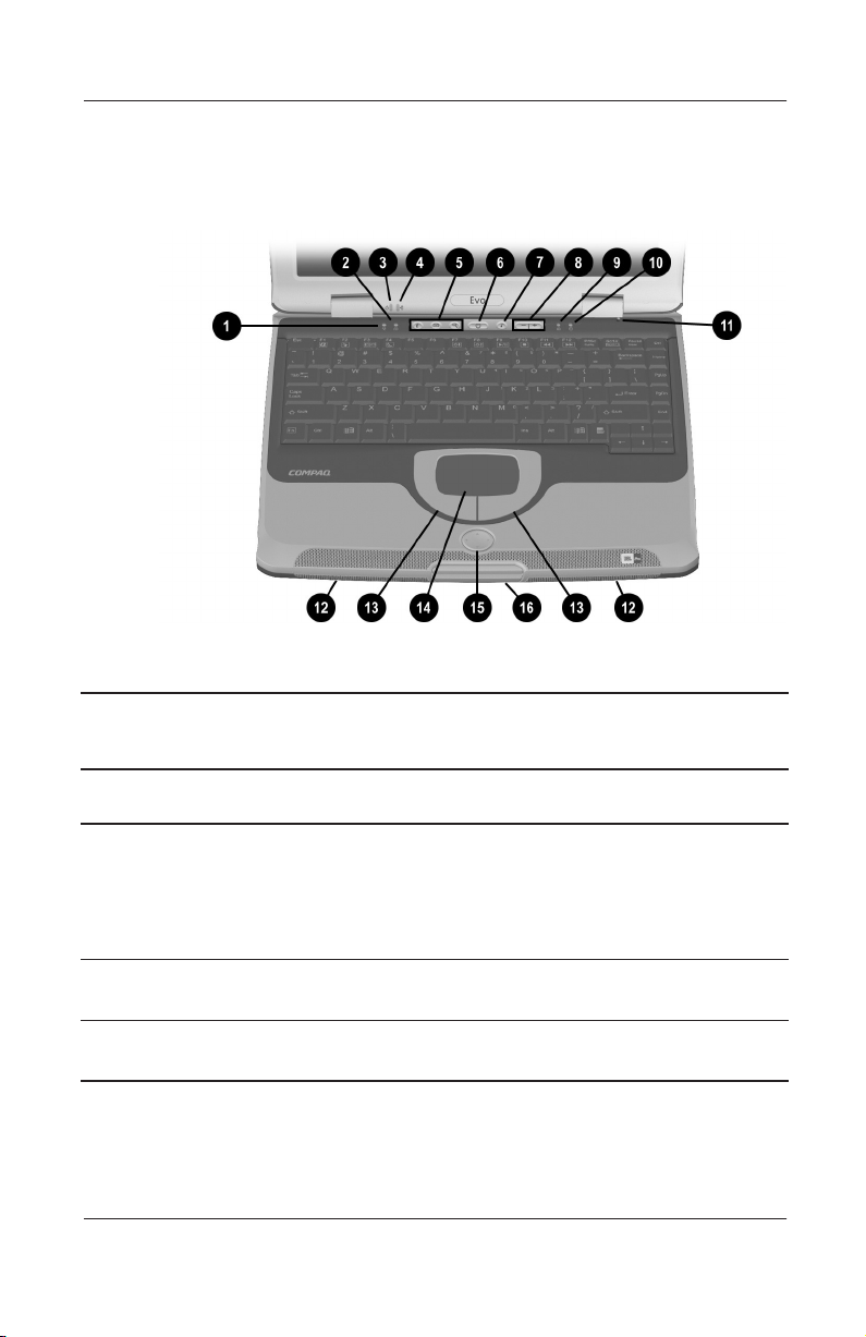
The components on the top of the computer are shown in
Figure 1-6 and described in Table 1-6.
Figure 1-6. Top Components
Table 1-6
Top Components
Item Component Function
1 Power light On: Power is turned on.
Blinking: Computer is in Standby. The
power light also blinks if a battery pack that
is the only available power source reaches
a low-battery condition.
2 Num lock light On: Num lock is on and the embedded
numeric keypad is enabled.
3 Drive activity light Turns on when the hard drive, CD-, or
DVD-ROM drive is accessed.
1–18 Maintenance and Service Guide
Page 24

Product Description
Table 1-6
Top Components
Item Component Function
4 Battery light On: A battery pack is charging.
Blinking: A battery pack that is the only
available power source has reached a
low-battery condition.
5 Easy Access buttons (3) Provide quick access to the Internet. Refer
to the
computer for information about these
buttons.
6 Power button Turns on the computer. Use the operating
system Shut Down command to turn off the
computer.
7 Digital audio button Launches Windows Media Player to play
MP3 music.
8 Volume control buttons Adjust the volume of the stereo speakers.
(Continued)
Hardware Guide
that ships with the
9 Caps lock light On: Caps lock is on.
10 Drive activity light Turns on when the hard drive, CD-, or
DVD-ROM drive is accessed.
11 Display lid switch Turns off the computer display if the
computer is closed while on.
12 Stereo speakers Produce stereo sound.
13 TouchPad buttons Function like the left and right mouse
buttons on an external mouse.
14 TouchPad Moves the mouse cursor, selects, and
activates.
15 EasyScroll button Scrolls the screen left, right, up, and down.
16 Display release latch Opens the computer.
Maintenance and Service Guide 1–19
Page 25
Product Description
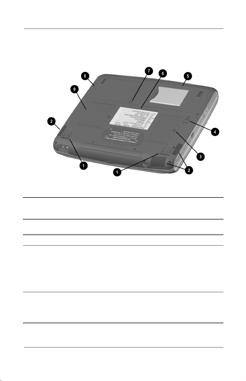
The external components on the bottom of the computer are
shown in Figure 1-7 and described in Table 1-7.
Figure 1-7. Bottom Components
Table 1-7
Bottom Components
Item Component Function
1 Tilt feet Tilt the computer for ease of use.
2 Vents Allow airflow to cool internal
components.
CAUTION: To prevent damage, the computer shuts down if
Ä
an overheating condition occurs. Do not block the cooling
vent. Avoid placing the computer on a blanket, rug, or other
flexible surface that may cover the vent area.
3 Memory expansion
compartment
1–20 Maintenance and Service Guide
Covers the memory expansion
compartment that contains two
memory expansion slots for
memory expansion boards.
Page 26

Product Description
Table 1-7
Bottom Components
Item Component Function
4 Battery pack release switch Releases the battery pack from
5 Battery bay Accepts an 8-cell Lithium ion
6 Label area Contains the serial number and
7 Hard drive retention screw Secures the hard drive to the
8 Hard drive bay Supports the removable primary
(Continued)
the battery compartment.
(li ion) battery pack.
Microsoft Certificate of Authenticity
labels, which may be needed
when you call Compaq customer
support or use some Windows
operating systems.
computer.
hard drive. The hard drive is
secured to the computer by one
screw.
9 Mini PCI compartment Contains the mini PCI modem
card.
Maintenance and Service Guide 1–21
Page 27

Product Description
1.6 Design Overview
This section presents a design overview of key parts and features
of the computer. Refer to Chapter 3, “Illustrated Parts Catalog,” to
identify replacement parts, and Chapter 5, “Removal and
Replacement Procedures,” for disassembly steps. The system
board provides the following device connections:
Memory expansion board
■
Hard drive
■
Display
■
Keyboard/TouchPad or pointing stick
■
Audio
■
AMD Athlon and Duron processors
■
Fan
■
PC Card
■
Modem or modem/NIC
■
The computer uses an electrical fan for ventilation. The fan is
controlled by a temperature sensor and is designed to turn on
automatically when high temperature conditions exist. These
conditions are affected by high external temperatures, system
power consumption, power management/battery conservation
configurations, battery fast charging, and software applications.
Exhaust air is displaced through the ventilation grill located on
the left side of the computer.
CAUTION: To properly ventilate the computer, allow at least a
Ä
3-inch (7.6 cm) clearance on the left and right sides of the
computer.
1–22 Maintenance and Service Guide
Page 28

Troubleshooting
WARNING: Only authorized technicians trained by Compaq should
Å
repair this equipment. All troubleshooting and repair procedures
are detailed to allow only subassembly/module level repair.
Because of the complexity of the individual boards and
subassemblies, no one should attempt to make repairs at the
component level or to make modifications to any printed wiring
board. Improper repairs can create a safety hazard. Any indication
of component replacement or printed wiring board modification may
void any warranty or exchange allowances.
Utilities that are preinstalled on the computer include:
PhoenixBIOS Setup Utility—Allows you to modify or
■
restore factory default settings and configure the system
BIOS to diagnose and solve minor problems.
Power Management—Allows you to reduce your computer
■
power consumption.
2
Security—Allows you to set or remove your power-on
■
password.
2.1 Using the PhoenixBIOS Setup Utility
The PhoenixBIOS Setup Utility (PSU) is built into the system.
You can configure the system BIOS and modify or restore factory
default settings, such as date and time, types of disk drives, power
management, anfd password settings. To run PSU, press the
key during system startup. When the main screen displays, use
the keyboard and arrow keys to move around the menus and make
selections.
Maintenance and Service Guide 2–1
F10
Page 29

Troubleshooting
2.2 Troubleshooting Flowcharts
Tabl e 2 - 1
Troubleshooting Flowcharts Overview
Flowchart Description
2.1 Initial troubleshooting
2.2 No power, part 1
2.3 No power, part 2
2.4 No power, part 3
2.5 No power, part 4
2.6 No video, part 1
2.7 No video, part 2
2.8 Nonfunctioning docking station
2.9 No operating system (OS) loading
2.10 No OS loading from hard drive, part 1
2.11 No OS loading from hard drive, part 2
2.12 No OS loading from hard drive, part 3
2.13 No OS loading from diskette drive
2.14 No OS loading from CD- or DVD-ROM drive
2.15 No audio, part 1
2.16 No audio, part 2
2.17 Nonfunctioning device
2.18 Nonfunctioning keyboard
2.19 Nonfunctioning pointing device
2.20 No network or modem connection
2–2 Maintenance and Service Guide
Page 30
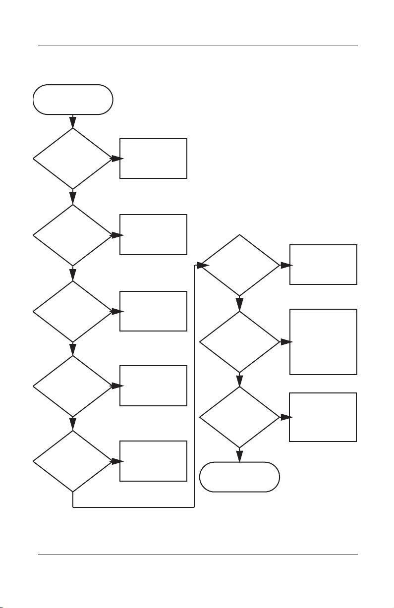
Flowchart 2.1 - Initial Troubleshooting
Begin
troubleshooting.
N
Is there
power?
Y
N
Beeps,
LEDs, or error
messages?
Y
N
Is there video?
(no boot)
Y
N
Is the OS
loading?
Y
N
Is there
sound?
Y
Go to
Section 2.2,
No Power.
Check
LED board,
speaker
connections.
Go to
Section 2.6,
No Video.
Go to
Section 2.9,
No OS Loading.
Go to
Section 2.15,
No Audio.
All drives
working?
Y
Keyboard/
pointing device
working?
Y
Connecting
to network
or modem?
Y
End
Troubleshooting
N
Section 2.17,
Nonfunctioning
N
Section 2.18,
Nonfunctioning
or Section 2.19,
Nonfunctioning
Pointing Device.
N
Section 2.20,
No Network or
Go to
Device.
Go to
Keyboard,
Go to
Modem.
Maintenance and Service Guide 2–3
Page 31

Troubleshooting
Flowchart 2.2 - No Power, Part 1
No Power
(power LED
is off).
Remove from
docking station
(if applicable).
N
Power up
on battery
power?
*Reset
power.
Y
N
Power up
on AC
power?
*Reset
power.
Y
Y
Power up
in docking
station?
Done
N
1. Reseat the power cables in the docking
station and at the AC outlet.
2. Ensure the AC power source is active.
3. Ensure that the power strip is working.
YN
Done
Power up
in docking
station?
N
Power up
on battery
power?
Go to
Section 2.3,
No Power,
Part 2.
Y
N
Power up
on AC
power?
Go to
Section 2.4,
No Power,
Part 3.
Y
*Notes:
1. On some models there is a separate
reset button.
2. On some models the computer may be
reset using the Standby switch and
either the lid switch or the main power
switch.
Go to
Section 2.8,
Nonfunctioning
Docking Station.
2–4 Maintenance and Service Guide
Page 32

Flowchart 2.3 - No Power, Part 2
Continued from
Section 2.2,
No Power, Part 1.
Visually check for
debris in battery
socket and clean if
necessary.
Y
Troubleshooting
Power on?
N
Check battery by
recharging,
moving it to
another computer,
or replacing it.
Power on?
Y
Done
Done
N
Replace power
supply (if
applicable).
N
Go to
Power on?
Section 2.4,
No Power,
Part 3.
Y
Done
Maintenance and Service Guide 2–5
Page 33

Troubleshooting
Flowchart 2.4 - No Power, Part 3
Continued from
Section 2.3,
No Power, Part 2.
Plug directly
into AC outlet.
Y
Power LED
on?
N
Reseat AC adapter
in computer and
at power source.
Power on?
N
Power outlet
active?
Y
Replace
power cord.
Power on?
Done
Y
Done
N
Try different
outlet.
Internal or
external AC
Internal
Section 2.5,
No Power,
Y
Done Done
adapter?
Go to
Part 4.
External
Replace external
AC adapter.
N
Power on?
Y
N
2–6 Maintenance and Service Guide
Page 34

Flowchart 2.5 - No Power, Part 4
Continued from
Section 2.4,
No Power, Part 3.
Open
computer.
Troubleshooting
Loose or
damaged
parts?
N
Close
computer and
retest.
Power on?
Y
Done
Y
Reseat loose
components and
boards and
replace
damaged items.
N
Replace the following items (if applicable).
Check computer operation after each
replacement:
1. Internal DC-DC converter*
2. Internal AC adapter
3. Processor board*
4. System board*
*Replace these items as a set to prevent
shorting out among components.
Maintenance and Service Guide 2–7
Page 35

Troubleshooting
Flowchart 2.6 - No Video, Part 1
No Video.
Docking
Station
Stand-alone
or Docking
Station?
Go to
Section 2.7,
No Video, Part 2.
*Note: To change from internal to
external display, use the hotkey
combination.
Stand-alone
Y
Internal or
external
display*?
External
Adjust
brightness.
Internal
Y
Video OK? Done
N
Check for bent
pins on cable.
N
Video OK?
Adjust
brightness.
Video OK? Done
N
A
Press lid
switch to ensure
operation.
Y
Video OK? Done
N
Replace the following one at a time. Test after each replacement.
1. Cable between notebook and computer display (if applicable)
2. Inverter board (if applicable)
3. Display
4. System board
N
Try
another
display.
Internal and
external
video OK?
Replace
system
board.
YY
Done
2–8 Maintenance and Service Guide
Done
Page 36

Flowchart 2.7 - No Video, Part 2
Continued from
Section 2.6,
No Video, Part 1.
Remove
notebook from
docking station,
if connected.
Troubleshooting
Adjust
display
brightness.
N
Go to “A” in
Video OK?
Section 2.6,
No Video, Part 1.
Y
Check that notebook is properly
seated in docking station, for bent
pins on cable, and for monitor
connection.
Y
Video OK?
N
Adjust external
monitor display.
Done
Check brightness
of external
monitor.
Video OK?
N
Try another
external
monitor.
Internal
and external
video OK?
N
Go to Section 2.8,
Nonfunctioning
Docking Station.
Y
Done
Y
Done
Maintenance and Service Guide 2–9
Page 37

Troubleshooting
Flowchart 2.8 - Nonfunctioning Docking Station
(if applicable)
Nonfunctioning
Docking Station.
Reseat power
cord in docking
station and
power outlet.
Check voltage
setting on
docking station.
Reset monitor
cable connector at
docking station.
Docking
station
operating?
N
Remove
notebook, reseat
all internal parts,
and replace any
damaged items in
docking station.
Reinstall
notebook into
docking station.
Y
Docking
station
operating?
Done
N
Y
Done
Replace the following docking station
components one at a time. Check
computer operation after each
replacement.
1. Power supply
2. I/O board
3. Backplane board
4. Switch box
2–10 Maintenance and Service Guide
Page 38

Troubleshooting
Flowchart 2.9 - No Operating System (OS) Loading
No OS
Loading.*
Reseat power
cord in docking
station and
power outlet.
No OS loading
from hard drive,
go to
Section 2.10.
No OS loading
from diskette
drive, go to
Section 2.13.
No OS loading
from CD- or
DVD-ROM drive,
go to
Section 2.14.
No OS loading
from network,
go to
Section 2.20.
*Before beginning troubleshooting, always
check cable connections, cable ends, and
drives for bent or damaged pins.
Maintenance and Service Guide 2–11
Page 39

Troubleshooting
Flowchart 2.10 - No OS Loading from Hard Drive, Part 1
OS not
loading from
hard drive.
Nonsystem
disk message?
N
Reseat
external
hard drive.
OS loading?
N
Boot
from
CD?
Y
Check the setup
utility for correct
booting order.
Y
Go to
Section 2.11,
No OS Loading
from Hard Drive,
Part 2.
Y
Done
N
N
Boot
from
diskette?
Y
Go to
Section 2.13,
No OS
Loading from
Diskette Drive.
N
Boot
from
hard drive?
Y
Done
Change boot
priority through
the setup utility
and reboot.
Boot
from
hard drive?
N
Go to
Section 2.17,
Nonfunctioning
Device.
Y
2–12 Maintenance and Service Guide
Page 40

Troubleshooting
Flowchart 2.11 - No OS Loading from Hard Drive, Part 2
Continued from
Section 2.10,
No OS Loading
from Hard Drive,
Part 1.
CD or
diskette in
drive?
Y
Remove
diskette and
reboot.
N
1. Replace hard
drive.
2. Replace system
board.
accessible?
N
Run FDISK.
Reseat
hard drive.
Hard drive
Y
Done
Boot
from
hard drive?
N
Boot
from diskette
drive?
Y
Hard drive
accessible?
Y
Go to
Section 2.12,
No OS Loading
from Hard Drive,
Part 3.
Y
N
No OS Loading
N
Done
Go to
Section 2.13,
from Diskette
Drive.
Done
Hard drive
partitioned?
Y
Hard drive
formatted?
Y
Y
Computer
booted?
Go to
Section 2.12,
No OS Loading
from Hard Drive,
Part 3.
N
Create partition,
then format hard
drive to bootable
C:\ prompt.
N
Format hard drive
and bring to a
bootable C:\
prompt.
Load OS using
Restore CD (if
N
applicable).
Maintenance and Service Guide 2–13
Page 41

Troubleshooting
Flowchart 2.12 - No OS Loading from Hard Drive, Part 3
Continued from
Section 2.11,
No OS Loading
from Hard Drive,
Part 2.
N
System
files on hard
drive?
Y
Install OS
and reboot.
Virus
on hard
drive?
N
Run SCANDISK
and check for
bad sectors.
Can bad
sectors
be fixed?
Y
Fix bad
sectors.
Y
Clean virus.
OS
loading from
hard drive?
Y
Done
N
Y
Diagnostics
on diskette?
Replace
hard drive.
N
N
Replace
hard drive.
Run diagnostics
and follow
recommendations.
N
Boot from
hard drive?
Replace
hard drive.
Y
Done
2–14 Maintenance and Service Guide
Page 42

Troubleshooting
Y
Flowchart 2.13 - No OS Loading from Diskette Drive
OS not loading
from
diskette drive.
Nonsystem
disk message?
Boot
from another
device?
Y
Diskette
drive enabled
in the setup
utility?
Y
Y
N
N
Reseat
diskette drive.
Go to
Section 2.17,
Nonfunctioning
Device.
Enable drive
and cold boot
computer.
OS
loading?
N
Bootable
diskette
in drive?
YN
Check diskette
for system files.
Try different
diskette.
Nonsystem
disk error?
N
Done
N
Install bootable
diskette and
reboot computer.
Y
1. Replace
diskette drive.
2. Replace system
board.
Y
Clear CMOS.
Diskette
drive boot
order?
Change boot
priority using
the setup utility.
Maintenance and Service Guide 2–15
Refer to Section
1.2, “Clearing a
Password,” for
instructions.
Go to
Section 2.17,
Nonfunctioning
Device.
OS
loading?
NN
Y
Done
Page 43

Troubleshooting
Y
N
Flowchart 2.14 - No OS Loading from CD- or
DVD-ROM Drive
No OS
Loading from
CD- or
DVD-ROM Drive.
Boots from
CD or DVD?
N
Reseat
drive.
N
Y
N
Y
Disc
in drive?
Install
bootable disc.
Done
Boots from
CD or DVD?
Booting
from another
device?
Y
Y
N
Bootable
disc in
drive?
Try another
bootable disc.
Done
Go to
Section 2.17,
Nonfunctioning
Device.
Install bootable
disc and
reboot
computer.
Y
Booting
order
correct?
N
Correct boot
order using
the setup utility.
2–16 Maintenance and Service Guide
Clear CMOS.
Refer to Section
1.2, “Clearing a
Password,” for
instructions.
Go to
Section 2.17,
Nonfunctioning
Device.
Page 44

Flowchart 2.15 - No Audio, Part 1
Y
Turn up audio
No Audio.
internally or
externally.
N
Troubleshooting
Audio? Done
Notebook in
docking station
(if applicable)?
N
Go to
Section 2.16,
No Audio, Part 2.
Y
Undock
Replace the following docking station
components one at a time as applicable.
Check after each change.
1. Reseat docking station audio cable.
2. Replace audio cable.
3. Replace speaker.
4. Replace docking station audio board.
5. Replace backplane board.
Go to
Section 2.17,
Nonfunctioning
Device.
N
Internal
audio?
Y
Y
Audio? Done
N
Go to
Section 2.16,
No Audio, Part 2.
Maintenance and Service Guide 2–17
Page 45

Troubleshooting
Flowchart 2.16 - No Audio, Part 2
Continued from
Section 2.15,
No Audio, Part 1.
N
Audio
driver in OS
configured?
Y
N
Correct
drivers for
application?
Y
Connect to
external
speaker.
Reload
audio drivers.
Load drivers and
set configuration
in OS.
Replace audio
board and
Audio?
YN
2–18 Maintenance and Service Guide
speaker
connections in
notebook (if
applicable).
Audio? Done
1. Replace internal speakers.
2. Replace audio board
(if applicable).
3. Replace system board.
YN
Page 46

Flowchart 2.17 - Nonfunctioning Device
Nonfunctioning
Device.
Reseat
device.
Unplug the nonfunctioning device
from the notebook, inspect cables
and plugs for bent or broken pins or
Clear
CMOS.
other damage.
Y
Any physical
device detected?
N
Troubleshooting
Fix or
replace
broken item.
Reattach device.
Close notebook,
plug in power,
and reboot.
N
Device
boots
properly?
Y
Done
Maintenance and Service Guide 2–19
Possible bad hard
drive. Replace
drive.
Possible bad NIC.
Replace card. If
integrated NIC,
replace system
board.
Possible bad
diskette drive.
Replace drive.
Go to
Section 2.9,
No OS Loading.
Device
boots
properly?
Y
Done
N
Page 47

Troubleshooting
Flowchart 2.18 - Nonfunctioning Keyboard
Keyboard
not operating
properly.
Connect notebook
to good external
keyboard.
N
External
device
works?
Y
Reseat internal
keyboard
connector (if
applicable).
Replace
system
board.
N
OK?
Replace internal
keyboard or
cable.
Y
Y
Done Done
OK?
N
Replace
system
board.
2–20 Maintenance and Service Guide
Page 48

Troubleshooting
Flowchart 2.19 - Nonfunctioning Pointing Device
Pointing device
not operating
properly.
Connect notebook
to good external
pointing device.
N
External
device
works?
Y
Reseat internal
pointing device
connector
(if applicable).
Replace
system
board.
N
OK?
Replace internal
pointing device or
cable.
Y
Y
Done Done
OK?
N
Replace
system
board.
Maintenance and Service Guide 2–21
Page 49

Troubleshooting
Flowchart 2.20 - Network or Modem Connection
No network
or modem
connection.
N
Network
or modem jack
active?
Y
Digital
line?
N
NIC/modem
configured in OS?
Y
Replace jack or
Y
to nondigital
N
drivers and
reconfigure.
have jack
activated.
Connect
line.
Y
Reload
OK?
N
Done
Disconnect all
power from
the notebook
and open.
Replace
NIC/modem (if
applicable).
Y
Reseat
NIC/modem (if
applicable).
OK? Done
N
Replace
system
board.
2–22 Maintenance and Service Guide
Page 50

Illustrated Parts Catalog
This chapter provides an illustrated parts breakdown and a
reference for spare part numbers and option part numbers.
3.1 Serial Number Location
When ordering parts or requesting information, provide the
computer serial number and model number located on the bottom
of the computer (Figure 3-1).
3
Figure 3-1. Serial Number Location
Maintenance and Service Guide 3–1
Page 51

Illustrated Parts Catalog
3.2 Computer System Major Components
Figure 3-2. Computer System Major Components
3–2 Maintenance and Service Guide
Page 52

Spare Parts: Computer System Major Components
Item Description
1 Displays
Illustrated Parts Catalog
Table 3-1
Spare Part
Number
14.1-inch, XGA, CTFT
13.3-inch, XGA, CTFT
Plastics and Hardware Kit, includes: 254121-001
2a
2b
2c
2d
2e
2f
2g
2h
2i
2j
3 LED cover 254117-001
4 Keyboards
Left hinge cover
Right hinge cover
Optical drive rear alignment rail
Optical drive front alignment rail
Left side panel
Right side panel
Mini PCI slot cover
Memory expansion slot cover
Hard drive bezel
Battery bracket
Belgian
Brazilian
Danish
Dutch
French
Canadian
French
German
Italian
Japanese
254114-181
254114-201
254114-081
254114-331
254114-121
254114-051
254114-041
254114-061
254114-191
Latin American
Spanish
Norwegian
Polish
Portuguese
Spanish
Swedish
Swiss
Taiwanese
Thai
U.K. English
U.S. English
254108-001
254107-001
254114-162
254114-091
254114-241
254114-131
254114-072
254114-101
254114-111
254114-AB1
254114-281
254114-031
254114-001
Maintenance and Service Guide 3–3
Page 53

Illustrated Parts Catalog
Computer System Major Components (continued)
3–4 Maintenance and Service Guide
Page 54

Illustrated Parts Catalog
Table 3-1
Spare Parts: Computer System Major Components
Item Description
5 Heat spreader
Thermal Pad Kit (not illustrated)
6 Optical drives
(Continued)
Spare Part
Number
254124-001
265995-001
24X Max CD-ROM drive
8X Max CD-RW drive
8X Max DVD-ROM drive
8X Max DVD-ROM/CD-RW combination drive
7 Disk cell RTC battery 279769-001
8 Top cover 254116-001
9 Processors
AMD Mobile Athlon 4 1.1 GHz with PowerNow!
technology (includes 256 KB L2 cache)
AMD Mobile Athlon 4 1.0 GHz with PowerNow!
technology (includes 256 KB L2 cache)
AMD Mobile Athlon 4 900 MHz with PowerNow!
technology (includes 256 KB L2 cache)
AMD Mobile Duron 950 MHz with PowerNow!
technology (includes 64 KB L2 cache)
AMD Mobile Duron 900 MHz with PowerNow!
technology (includes 64 KB L2 cache)
AMD Mobile Duron 850 MHz with PowerNow!
technology (includes 64 KB L2 cache)
Processor Stopper Kit (not illustrated)
254110-001
254111-001
254112-001
254113-001
and
264298-001
254105-001
239184-001
239182-001
260738-001
249664-001
239181-001
265994-001
Cable Kit 254120-001
10a
10b
Diskette drive cable
Audio board cable
Maintenance and Service Guide 3–5
Page 55

Illustrated Parts Catalog
Computer System Major Components (continued)
3–6 Maintenance and Service Guide
Page 56

Illustrated Parts Catalog
Table 3-1
Spare Parts: Computer System Major Components
Item Description
11 Fan 254123-001
12 Diskette drive 254119-001
13 Audio board 254125-001
14 Charger board 254109-001
15 Mini PCI communication boards
(Continued)
Spare Part
Number
56-KBPS domestic modem
56-KBPS international modem
16 System boards
includes 256 MB SDRAM
includes 128 MB SDRAM
17 Speaker assembly 254118-001
18 Base enclosure 254115-001
19 Hard drives
40 GB
30 GB
20 GB
20 Battery packs
4.0 Amp hour capacity
3.6 Amp hour capacity
273491-001
192406-001
200350-001
15 GB
10 GB
248776-001
248777-002
273487-001
254103-001
216173-001
200349-001
247051-001
247050-001
Maintenance and Service Guide 3–7
Page 57

Illustrated Parts Catalog
3.3 Plastics and Hardware Kit Components
Figure 3-3. Plastics and Hardware Kit Components
Table 3-2
Plastics and Hardware Kit Components
Spare Part Number 254121-001
Item Description Item Description
1 Left hinge cover 6 Mini PCI slot cover
2 Right hinge cover 7 Left side panel
3 Optical drive rear
alignment rail
4 Optical drive front
alignment rail
5 Hard drive bezel 10 Memory expansion slot cover
3–8 Maintenance and Service Guide
8 Right side panel
9 Battery bracket
Page 58

3.4 Cable Kit Components
Figure 3-4. Cable Kit Components
Table 3-3
Kit Components
Cable
Spare Part Number 254120-001
Illustrated Parts Catalog
Item Description
1 Diskette drive cable
2 Audio board cable
Maintenance and Service Guide 3–9
Page 59

Illustrated Parts Catalog
3.5 Mass Storage Devices
Figure 3-5. Mass Storage Devices
l
Table 3-4
Mass Storage Devices
Spare Part
Item Description
1 Hard drives
30 GB
20 GB
15 GB
10 GB
Number
192406-001
200350-001
216173-001
200349-001
3–10 Maintenance and Service Guide
Page 60

Illustrated Parts Catalog
Table 3-4
Mass Storage Devices
Item Description
2 Diskette drive 254119-001
3 Optical drives
(Continued)
Spare Part
Number
24X Max CD-ROM drive
8X Max CD-RW drive
8X Max DVD-ROM drive
DVD-ROM/CD-RW combination drive
254110-001
254111-001
254112-001
254113-001
and
264298-001
Maintenance and Service Guide 3–11
Page 61

Illustrated Parts Catalog
3.6 Miscellaneous
Tabl e 3 - 5
Spare Parts: Miscellaneous (not illustrated)
Spare Part
Description
Logo Kit 255353-001
Screw Kit (includes the following screws, standoffs, and
screwlocks; refer to Appendix C, “Screw Listing,” for more
information on screw specifications and usage.)
Number
254122-001
PM2.0 x 7.0
■
PM2.5 x 3.5
■
PM2.0 x 5.0
■
TM2.0 x 7.5
■
TM2.0 x 5.0
■
TM2.0 x 8.0
■
TM2.0 x 20.0
■
AC adapters
60-Watt AC adapter power supply (2-wire)
60-Watt AC adapter power supply (3-wire)
Power cord, 3-wire
Danish
International
Italian
Japanese
170513-081
170513-002
170513-061
293831-291
Memory expansion boards
256 MB
128 MB
HM5.0 x 13.0 standoff
■
HM5.0 x 17.5 standoff
■
HM5.0 x 9.0 standoff
■
HM5.0 x 10.5 screwlock
■
180676-001
180675-001
Swiss
U.K. English
170513-115
170513-031
North
America
293831-001
244399-001
239190-001
3–12 Maintenance and Service Guide
Page 62

Removal and Replacement
This chapter provides essential information for proper and safe
removal and replacement service.
4.1 Tools Required
You will need the following tools to complete the removal and
replacement procedures:
Magnetic screwdriver
■
Phillips P0 screwdriver
■
5.0-mm hex socket (for system board screwlocks)
■
Tool kit (includes connector removal tool, loopback plugs,
■
and case utility tool)
4
Preliminaries
Maintenance and Service Guide 4–1
Page 63

Removal and Replacement Preliminaries
4.2 Service Considerations
The following sections include some of the considerations that
you should keep in mind during disassembly and assembly
procedures.
As you remove each subassembly from the computer, place the
✎
subassembly (and all accompanying screws) away from the work
area to prevent damage.
Plastic Parts
Using excessive force during disassembly and reassembly can
damage plastic parts. Use care when handling the plastic parts.
Apply pressure only at the points designated in the maintenance
instructions.
Cables and Connectors
Cables must be handled with extreme care to avoid damage.
Apply only the tension required to unseat or seat the cables
during removal and insertion. Handle cables by the connector
whenever possible. In all cases, avoid bending, twisting, or
tearing cables. Ensure that cables are routed in such a way that
they cannot be caught or snagged by parts being removed or
replaced. Handle flex cables with extreme care; these cables tear
easily.
CAUTION: When servicing the computer, ensure that cables are
Ä
placed in their proper locations during the reassembly process.
Improper cable placement can damage the computer.
4–2 Maintenance and Service Guide
Page 64

Removal and Replacement Preliminaries
4.3 Preventing Damage to
Removable Drives
Removable drives are fragile components that must be handled
with care. To prevent damage to the computer, damage to a
removable drive, or loss of information, observe the following
precautions:
Before removing or inserting a hard drive, shut down the
■
computer. If you are unsure whether the computer is off or in
Hibernation, turn the computer on, then shut it down.
Before removing a diskette drive or optical drive, ensure that
■
a diskette or disc is not in the drive. Ensure that the optical
drive tray is closed.
Before handling a drive, ensure that you are discharged of
■
static electricity. While handling a drive, avoid touching the
connector.
Handle drives on surfaces that have at least one inch of
■
shock-proof foam.
Avoid dropping drives from any height onto any surface.
■
After removing a hard drive, CD-ROM drive, or a diskette
■
drive, place it in a static-proof bag.
Avoid exposing a hard drive to products that have magnetic
■
fields, such as monitors or speakers.
Avoid exposing a drive to temperature extremes or to liquids.
■
If a drive must be mailed, place the drive in a bubble pack
■
mailer or other suitable form of protective packaging and
label the package “Fragile: Handle With Care.”
Maintenance and Service Guide 4–3
Page 65

Removal and Replacement Preliminaries
4.4 Preventing Electrostatic Damage
Many electronic components are sensitive to electrostatic
discharge (ESD). Circuitry design and structure determine the
degree of sensitivity. Networks built into many integrated circuits
provide some protection, but in many cases the discharge contains
enough power to alter device parameters or melt silicon junctions.
A sudden discharge of static electricity from a finger or other
conductor can destroy static-sensitive devices or microcircuitry.
Often the spark is neither felt nor heard, but damage occurs.
An electronic device exposed to electrostatic discharge may not
be affected at all and can work perfectly throughout a normal
cycle. Or the device may function normally for a while, then
degrade in the internal layers, reducing its life expectancy.
4.5 Packaging and Transporting Precautions
Use the following grounding precautions when packaging and
transporting equipment:
To avoid hand contact, transport products in static-safe
■
containers such as tubes, bags, or boxes.
Protect all electrostatic-sensitive parts and assemblies with
■
conductive or approved containers or packaging.
Keep electrostatic-sensitive parts in their containers until the
■
parts arrive at static-free workstations.
Place items on a grounded surface before removing items
■
from their containers.
Always be properly grounded when touching a sensitive
■
component or assembly.
4–4 Maintenance and Service Guide
Page 66

Removal and Replacement Preliminaries
Store reusable electrostatic-sensitive parts from assemblies in
■
protective packaging or nonconductive foam.
Use transporters and conveyers made of antistatic belts and
■
roller bushings. Ensure that mechanized equipment used for
moving materials is wired to ground and that proper materials
are selected to avoid static charging. When grounding is not
possible, use an ionizer to dissipate electric charges.
4.6 Workstation Precautions
Use the following grounding precautions at workstations:
Cover the workstation with approved static-dissipative
■
material (refer to Table 4-2).
Use a wrist strap connected to a properly grounded work
■
surface and use properly grounded tools and equipment.
Use conductive field service tools, such as cutters,
■
screwdrivers, and vacuums.
When using fixtures that must directly contact dissipative
■
surfaces, only use fixtures made of static-safe materials.
Keep the work area free of nonconductive materials such as
■
ordinary plastic assembly aids and Styrofoam.
Handle electrostatic-sensitive components, parts, and
■
assemblies by the case or PCM laminate. Handle these items
only at static-free workstations.
Avoid contact with pins, leads, or circuitry.
■
Turn off power and input signals before inserting or removing
■
connectors or test equipment.
Maintenance and Service Guide 4–5
Page 67

Removal and Replacement Preliminaries
4.7 Grounding Equipment and Methods
Grounding equipment must include either a wrist strap or a foot
strap at a grounded workstation.
When seated, wear a wrist strap connected to a grounded
■
system. Wrist straps are flexible straps with a minimum of
one megohm ±10% resistance in the ground cords. To
provide proper ground, wear a strap snugly against the skin at
all times. On grounded mats with banana-plug connectors,
connect a wrist strap with alligator clips.
When standing, use foot straps and a grounded floor mat.
■
Foot straps (heel, toe, or boot straps) can be used at standing
workstations and are compatible with most types of shoes or
boots. On conductive floors or dissipative floor mats, use foot
straps on both feet with a minimum of one-megohm
resistance between the operator and ground. To be effective,
the conductive strips must be worn in contact with the skin.
Other grounding equipment recommended for use in preventing
electrostatic damage includes:
Antistatic tape
■
Antistatic smocks, aprons, and sleeve protectors
■
Conductive bins and other assembly or soldering aids
■
Nonconductive foam
■
Conductive tabletop workstations with ground cords of
■
one-megohm resistance
Static-dissipative tables or floor mats with hard ties to
■
the ground
Field service kits
■
Static awareness labels
■
Material-handling packages
■
4–6 Maintenance and Service Guide
Page 68

Removal and Replacement Preliminaries
Nonconductive plastic bags, tubes, or boxes
■
Metal tote boxes
■
Electrostatic voltage levels and protective materials
■
Table 4-1 shows how humidity affects the electrostatic voltage
levels generated by different activities.
Table 4-1
Typical Electrostatic Voltage Levels
Relative Humidity
Event 10% 40% 55%
Walking across carpet 35,000 V 15,000 V 7,500 V
Walking across vinyl floor 12,000 V 5,000 V 3,000 V
Motions of bench worker 6,000 V 800 V 400 V
Removing DIPS from plastic tube 2,000 V 700 V 400 V
Removing DIPS from vinyl tray 11,500 V 4,000 V 2,000 V
Removing DIPS from Styrofoam 14,500 V 5,000 V 3,500 V
Removing bubble pack from PCB 26,500 V 20,000 V 7,000 V
Packing PCBs in foam-lined box 21,000 V 11,000 V 5,000 V
A product can be degraded by as little as 700 volts.
✎
Table 4-2 lists the shielding protection provided by antistatic bags
and floor mats.
Table 4-2
Static-Shielding Materials
Material Use Voltage Protection Level
Antistatic plastic Bags 1,500 V
Carbon-loaded plastic Floor mats 7,500 V
Metallized laminate Floor mats 5,000 V
Maintenance and Service Guide 4–7
Page 69

5
Removal and Replacement
Procedures
This chapter provides removal and replacement procedures.
Phillips P1 and Torx T8 screws are removed during disassembly.
There are 62 screws, standoffs, and screwlocks, in 11 different
sizes, that must be removed and replaced when servicing the
computer. Make special note of each screw size and location
during removal and replacement.
Refer to Appendix C, “Screw Listing,” for detailed information
on screw sizes, locations, and usage.
Maintenance and Service Guide 5–1
Page 70

Removal and Replacement Procedures
5.1 Serial Number
Report the computer serial number to Compaq when requesting
information or ordering spare parts. The serial number is located
on the bottom of the computer (Figure 5-1).
Figure 5-1. Serial Number Location
5–2 Maintenance and Service Guide
Page 71

Removal and Replacement Procedures
5.2 Disassembly Sequence Chart
Use the chart below to determine the section number to be
referenced when removing computer components.
Table 5-1
Disassembly Sequence Chart
Section Description # of Screws Removed
5.3 Preparing the computer for disassembly
Battery pack 0
Hard drive 1 to remove hard drive
4 to separate hard drive
from hard drive
bracket
5.4 Computer feet 0
5.5 Memory expansion board 1
5.6 Mini PCI communications board 1
5.7 Optical Drive 2
5.8 LED cover 2
5.9 Keyboard 0
5.10 Display 7
5.11 Heat spreader 7
Maintenance and Service Guide 5–3
Page 72

Removal and Replacement Procedures
Table 5-1
Disassembly Sequence Chart
Section Description # of Screws Removed
5.12 Processor 0
5.13 Disk cell RTC battery 0
5.14 Top cover 12
5.15 Diskette drive 1
5.16 Charger board 1
5.17 Left side panel 3 screws
5.18 Right side panel 3
5.19 Speaker assembly 0
5.20 Audio board 2
5.21 Fan 2
5.22 System board 5 screws
(Continued)
1 standoff
3 standoffs
4 screwlocks
5.3 Preparing the Computer for Disassembly
Perform the following steps before disassembling the computer:
1. Turn off the computer.
2. Disconnect the AC adapter and all external devices.
5–4 Maintenance and Service Guide
Page 73

Removal and Replacement Procedures
3. Remove the battery pack by following these steps:
a. Turn the computer bottom side up with the front facing
forward.
b. Slide and hold the battery release latch
of the computer (Figure 5-2). The left edge of the battery
bracket rises up
Figure 5-2. Releasing the Battery Pack
2
.
toward the back
1111
Maintenance and Service Guide 5–5
Page 74

Removal and Replacement Procedures
c. Lift and hold the battery bracket open as far as it will
open
(Figure 5-3).
1
d. Grasp the edges of the battery pack and slide it to the left
to remove it
2
.
Figure 5-3. Removing the Battery Pack
5–6 Maintenance and Service Guide
Page 75

Removal and Replacement Procedures
e. Press in on the tabs on the battery bracket retention
arms
right
and swing the battery bracket up and to the
1
(Figure 5-4).
2
f. Lift the battery bracket straight up to remove it
Figure 5-4. Removing the Battery Bracket
The battery bracket is included in the Plastics and Hardware Kit
✎
(spare part number 254121-001).
3
.
Reverse the above procedures to install the battery pack and
battery bracket.
Maintenance and Service Guide 5–7
Page 76

Removal and Replacement Procedures
4. Remove the hard drive by following these steps:
a. Remove the battery pack (Section 5.3).
b. Remove the black PM2.0 × 7.0 hard drive retention
screw
(Figure 5-5).
1
c. Slide the hard drive to the right to unseat the hard drive
connector
2
.
Figure 5-5. Releasing the Hard Drive
5–8 Maintenance and Service Guide
Page 77

Removal and Replacement Procedures
d. Swing the right side of the hard drive up and to the left
until it is resting at an angle (Figure 5-6).
e. Lift the hard drive straight up and remove it
Figure 5-6. Removing the Hard Drive
2
.
Maintenance and Service Guide 5–9
Page 78

Removal and Replacement Procedures
5. If the hard drive must be removed from the hard drive bezel,
perform the following steps:
a. Remove the four silver PM2.5 × 3.5 screws
the hard drive to the hard drive bezel (Figure 5-7).
b. Slide the hard drive forward
hard drive bezel.
Figure 5-7. Removing the Hard Drive from the Hard
Drive Bezel
and remove it from the
2
1
that secure
The hard drive bezel is included in the Plastics and Hardware Kit
✎
(spare part number 254121-001).
Reverse the above procedure to install the hard drive.
5–10 Maintenance and Service Guide
Page 79

5.4 Computer Feet
The computer feet are adhesive-backed rubber pads. The
computer feet are included in the Plastics and Hardware Kit
(spare part number 254121-001). The computer feet attach to the
battery bracket and hard drive bezel as illustrated in Figure 5-8.
Removal and Replacement Procedures
Figure 5-8. Replacing the Computer Feet
5.5 Memory Expansion Board
Memory Expansion Boards
Spare Part Number Information
Memory expansion boards
256 MB
128 MB
Maintenance and Service Guide 5–11
244399-001
239190-001
Page 80

Removal and Replacement Procedures
1. Prepare the computer for disassembly (Section 5.3).
2. Turn the computer bottom side up with the front
facing forward.
3. Remove the black PM2.0 × 5.0 screw
memory expansion compartment cover to the base enclosure
(Figure 5-9).
4. Swing the left side of the cover up and to the right until it
rests at an angle
5. Lift the cover straight up and remove it
2
.
that secures the
1
.
3
Figure 5-9. Removing the Memory Expansion
Compartment Cover
The memory expansion compartment cover is included in the
✎
Plastics and Hardware Kit (spare part number 254121-001).
5–12 Maintenance and Service Guide
Page 81

Removal and Replacement Procedures
6. Spread the memory expansion slot retaining tabs to release
the memory expansion board
. The board tilts up at a
1
45-degree angle (Figure 5-10).
7. Remove the board by pulling it away from the connector at a
45-degree angle
2
.
Figure 5-10. Removing a Memory Expansion Board
Reverse the above procedure to install a memory
expansion board.
5.6 Mini PCI Communications Board
Mini PCI Communication Boards
Spare Part Number Information
Mini PCI communication boards
56-KBPS domestic modem
56-KBPS international modem
Maintenance and Service Guide 5–13
248776-001
248777-002
Page 82

Removal and Replacement Procedures
1. Prepare the computer for disassembly (Section 5.3).
2. Turn the computer bottom side up with the front facing
forward.
3. Remove the black PM2.0 × 5.0 screw
PCI communications slot cover to the base enclosure
(Figure 5-11).
4. Swing the left side of the cover up and to the right until it
rests at an angle
5. Lift the cover straight up and remove it
The mini PCI communications slot cover is included in the
✎
Plastics and Hardware Kit (spare part number 254121-001).
2
.
that secures the mini
1
.
3
Figure 5-11. Removing the Mini PCI Communications
Slot Cover
5–14 Maintenance and Service Guide
Page 83

Removal and Replacement Procedures
6. Spread the retaining tabs to release the mini PCI
communications board
. The board tilts up at a 45-degree
1
angle (Figure 5-12).
7. Remove the board by pulling it away from the connector at a
45-degree angle
2
.
Figure 5-12. Removing a Mini PCI Communications Board
Reverse the above procedure to install a mini PCI
communications board.
Maintenance and Service Guide 5–15
Page 84

Removal and Replacement Procedures
5.7 Optical Drive
Optical Drives
Spare Part Number Information
Optical drives
24X Max CD-ROM drive
8X Max CD-RW drive
8X Max DVD-ROM drive
8X Max DVD-ROM/CD-RW combination drive
1. Prepare the computer for disassembly (Section 5.3).
2. Turn the computer bottom side up with the front facing
forward.
3. Remove the two pewter TM2.0 × 7.5 screws that secure the
optical drive to the base enclosure (Figure 5-13).
254110-001
254111-001
254112-001
254113-001
and
264298-001
Figure 5-13. Removing the Optical Drive Screws
5–16 Maintenance and Service Guide
Page 85

Removal and Replacement Procedures
4. Turn the computer top side up with the front facing forward.
5. Insert a paper clip or similar thin metal rod into the manual
release hole on the front bezel of the optical drive
1
(Figure 5-14). Press firmly.
6. Grasp the drive bezel and slide the drive out of the optical
drive bay
2
.
Figure 5-14. Removing the Optical Drive
Reverse the above procedure to install the optical drive.
Maintenance and Service Guide 5–17
Page 86

Removal and Replacement Procedures
5.8 LED Cover
LED Cover
Spare Part Number Information
LED cover 254117-001
1. Prepare the computer for disassembly (Section 5.3).
2. Turn the computer bottom side up with the rear panel facing
forward.
3. Remove the two pewter TM2.0 × 7.5 screws that secure the
LED cover to the base enclosure (Figure 5-15).
Figure 5-15. Removing the LED Cover Screws
4. Turn the computer top side up with front facing forward.
5. Open the computer as far as it will open.
5–18 Maintenance and Service Guide
Page 87

Removal and Replacement Procedures
6. Press the
cover
and F1 keys to reveal the slot in the LED
Esc
(Figure 5-16).
1
7. Insert a flat-bladed tool into the slot in the LED cover and lift
the left side of the LED cover up
8. Lift the LED cover up from left to right
2
.
.
3
Figure 5-16. Removing the LED Cover
9. Remove the LED cover.
Reverse the above procedure to install the LED cover.
Maintenance and Service Guide 5–19
Page 88

Removal and Replacement Procedures
5.9 Keyboard
Keyboards
Spare Part Number Information
Keyboards
Belgian
Brazilian
Danish
Dutch
French Canadian
French
German
Italian
Japanese
Latin American
Spanish
254114-181
254114-201
254114-081
254114-331
254114-121
254114-051
254114-041
254114-061
254114-191
254114-162
Norwegian
Polish
Portuguese
Spanish
Swedish
Swiss
Taiwanese
Thai
U.K. English
U.S. English
1. Prepare the computer for disassembly (Section 5.3).
2. Remove the LED cover (Section 5.8).
254114-091
254114-241
254114-131
254114-072
254114-101
254114-111
254114-AB1
254114-281
254114-031
254114-001
5–20 Maintenance and Service Guide
Page 89

Removal and Replacement Procedures
3. Swing the back edge of the keyboard up and forward 1 and
rest it upside down on the palm rest
Figure 5-17. Releasing the Keyboard
(Figure 5-17).
2
Maintenance and Service Guide 5–21
Page 90

Removal and Replacement Procedures
4. Release the ZIF connector 1 to which the keyboard cable is
connected and disconnect the keyboard cable
(Figure 5-18).
Figure 5-18. Disconnecting the Keyboard Cable
2
5. Remove the keyboard.
Reverse the above procedure to install the keyboard.
5.10 Display
Displays
Spare Part Number Information
Displays
14.1-inch, XGA, CTFT
13.3-inch, XGA, CTFT
5–22 Maintenance and Service Guide
254108-001
254107-001
Page 91

Removal and Replacement Procedures
1. Prepare the computer for disassembly (Section 5.3).
2. Remove the LED cover (Section 5.8).
3. Remove the keyboard (Section 5.9).
4. Remove the two silver TM2.0 × 5.0 screws
that secure the
1
hinge covers to the base enclosure (Figure 5-19).
5. Lift the front edge of the hinge cover
until it separates from
2
the base enclosure.
Figure 5-19. Removing the Hinge Cover Screws
6. Position the display so it rests at a 90-degree angle in
relationship to the work surface.
Maintenance and Service Guide 5–23
Page 92

Removal and Replacement Procedures
7. Press forward on the back of the hinge cover 1 (Figure 5-20).
8. Remove the hinge cover
The display hinge covers are included in the Plastics and
✎
Hardware Kit (spare part number 254121-001).
Figure 5-20. Removing the Hinge Covers
2
.
5–24 Maintenance and Service Guide
Page 93

Removal and Replacement Procedures
9. Remove the pewter TM2.0 × 7.5 screw 1 that secures the
display backlight
and display video ground cables 3 to the
2
heat spreader (Figure 5-21).
Figure 5-21. Removing the Display Ground Cable Screw
Maintenance and Service Guide 5–25
Page 94

Removal and Replacement Procedures
10. Disconnect the display backlight cable 1 from the system
board and unroute the cable
from the heat spreader.
2
11. Disconnect the display video cable
and unroute the cable
Figure 5-22. Disconnecting and Unrouting the
Display Cables
from the heat spreader (Figure 5-22).
4
from the system board
3
5–26 Maintenance and Service Guide
Page 95

Removal and Replacement Procedures
12. Remove the four silver TM2.0 × 8.0 screws 1 that secure the
display to the base enclosure.
CAUTION: Secure the display when removing these screws. The
Ä
display is secured to the computer only by these screws and will fall
if not supported during screw removal.
13. Remove the display 2 (Figure 5-23).
Figure 5-23. Removing the Display
Maintenance and Service Guide 5–27
Page 96

Removal and Replacement Procedures
When installing the display, install the screws in the 1, 2, 3, 4
sequence shown in the Figure 5-24.
Figure 5-24. Installing the Display Screws
5.11 Heat Spreader
Heat Spreader
Spare Part Number Information
Heat spreader 254124-001
1. Prepare the computer for disassembly (Section 5.3) and
remove the following components:
a. LED cover (Section 5.8)
b. Keyboard (Section 5.9)
c. Display (Section 5.10)
5–28 Maintenance and Service Guide
Page 97

Removal and Replacement Procedures
2. Remove the three silver TM2.0 × 5.0 screws 1 that secure the
heat spreader to the base enclosure (Figure 5-25).
3. Remove the four silver TM2.0 × 20.0 spring-loaded screws
that secure the heat spreader to the base enclosure.
Figure 5-25. Removing the Heat Spreader Screws
2
Maintenance and Service Guide 5–29
Page 98

Removal and Replacement Procedures
The spring-loaded screws should be removed and installed in the
✎
1, 2, 3, 4
in Figure 5-26.
Figure 5-26. Heat Spreader Screw Sequence
sequence stamped into the heat spreader as illustrated
5–30 Maintenance and Service Guide
Page 99

Removal and Replacement Procedures
4. Lift up the front right side of the heat spreader 1 and slide it
forward
tab
Figure 5-27. Removing the Heat Spreader
until the back edge of the heat spreader clears the
2
on the base enclosure (Figure 5-27).
3
Maintenance and Service Guide 5–31
Page 100

Removal and Replacement Procedures
5. Lift up the right side of the heat spreader 1 until it rests at an
angle (Figure 5-28).
6. Slide the heat spreader to the right
until the left side of the
2
heat spreader clears the base enclosure.
7. Slide the heat spreader forward
8. Disconnect the fan cable
Figure 5-28. Removing the Heat Spreader (Continued)
4
and rest it on the palm rest.
3
from the system board.
9. Remove the heat spreader.
5–32 Maintenance and Service Guide
 Loading...