

Compaq Evo D310v, D310v - Compaq Evo - 256 MB RAM, Evo Desktop D310v Series Hardware Reference Manual
Page 1

b
Hardware Reference Guide
Compaq Evo Desktop D310v Series
Document Part Number: 293388-001
August 2002
This guide provides basic information about upgrading this series of
computers.
Page 2

Å
© 2002 Compaq Information Technologies, L.P.
Compaq, the Compaq logo, and Evo are trademarks of Compaq Information
Technologies Group, L.P. in the U.S. and other countries.
Microsoft, MS-DOS, Windows, and Windows NT are trademarks of Microsoft
Corporation in the U.S. and other countries.
All other product names mentioned herein may be trademarks of their respective
companies.
Compaq Computer Corporation shall not be liable for technical or editorial
errors or omissions contained herein or for incidental or consequential damages
in connection with the furnishing, performance, or use of this material. The
information in this document is provided “as is” without warranty of any kind,
including, but not limited to, the implied warranties of merchantability and
fitness for a particular purpose, and is subject to change without notice. The
warranties for Compaq products are set forth in the express limited warranty
statements accompanying such products. Nothing herein should be construed as
constituting an additional warranty.
This document contains proprietary information that is protected by copyright.
No part of this document may be photocopied, reproduced, or translated to
another language without the prior written consent of Compaq Computer
Corporation.
WARNING: Text set off in this manner indicates that failure to follow
directions could result in bodily harm or loss of life.
Ä
CAUTION: Text set off in this manner indicates that failure to follow
directions could result in damage to equipment or loss of information.
Hardware Reference Guide
Compaq Evo Desktop D310v Series
First Edition (August 2002)
Document Part Number: 293388-001
Page 3

Contents
1 Hardware Upgrades
Installation Sequence. . . . . . . . . . . . . . . . . . . . . . . . . . . . . . . . . . . . . . . . . . . . . . . . . . . 1–1
Removing the Access Panels. . . . . . . . . . . . . . . . . . . . . . . . . . . . . . . . . . . . . . . . . . . . . 1–2
Removing the Front Bezel. . . . . . . . . . . . . . . . . . . . . . . . . . . . . . . . . . . . . . . . . . . . . . . 1–4
Installing Additional Memory. . . . . . . . . . . . . . . . . . . . . . . . . . . . . . . . . . . . . . . . . . . . 1–5
Installing or Removing an Expansion Card . . . . . . . . . . . . . . . . . . . . . . . . . . . . . . . . . 1–7
Removing a 5.25 Inch Drive . . . . . . . . . . . . . . . . . . . . . . . . . . . . . . . . . . . . . . . . . . . . . 1–9
Removing a Diskette Drive or Hard Drive . . . . . . . . . . . . . . . . . . . . . . . . . . . . . . . . . 1–10
2 Battery Replacement
Replacing the Battery . . . . . . . . . . . . . . . . . . . . . . . . . . . . . . . . . . . . . . . . . . . . . . . . . . 2–1
3 Routine Care & Shipping Information
Routine Care . . . . . . . . . . . . . . . . . . . . . . . . . . . . . . . . . . . . . . . . . . . . . . . . . . . . . . . . . 3–1
CD-ROM Drive Precautions . . . . . . . . . . . . . . . . . . . . . . . . . . . . . . . . . . . . . . . . . . . . . 3–2
Operation . . . . . . . . . . . . . . . . . . . . . . . . . . . . . . . . . . . . . . . . . . . . . . . . . . . . . . . . 3–2
Cleaning . . . . . . . . . . . . . . . . . . . . . . . . . . . . . . . . . . . . . . . . . . . . . . . . . . . . . . . . . 3–2
Safety . . . . . . . . . . . . . . . . . . . . . . . . . . . . . . . . . . . . . . . . . . . . . . . . . . . . . . . . . . . 3–2
Shipping Preparation . . . . . . . . . . . . . . . . . . . . . . . . . . . . . . . . . . . . . . . . . . . . . . . . . . . 3–3
4 Electrostatic Discharge
Preventing Electrostatic Damage . . . . . . . . . . . . . . . . . . . . . . . . . . . . . . . . . . . . . . . . . 4–1
Grounding Methods. . . . . . . . . . . . . . . . . . . . . . . . . . . . . . . . . . . . . . . . . . . . . . . . . . . . 4–2
Index
Hardware Reference Guide iii
Page 4

Installation Sequence
It is very important that you follow this sequence of steps to ensure
the proper installation of any optional equipment.
For more information about Computer Setup, refer to the Computer
Setup (F10) Utility Guide.
1. If the computer is turned on, turn it off and disconnect the power
cord from the wall outlet.
WARNING: To reduce the risk of personal injury from electrical shock
Å
and/or hot surfaces, be sure to disconnect the power cord from the wall
outlet, and allow the internal system components to cool before touching.
1
Hardware Upgrades
WARNING: To reduce the risk of electrical shock, fire, or damage to the
Å
Ä
Hardware Reference Guide 1–1
equipment, do not plug telecommunications or telephone connectors into
the network interface controller (NIC) receptacles.
CAUTION: Static electricity can damage the electronic components of
the computer or optional equipment. Before beginning these procedures,
ensure that you are discharged of static electricity by briefly touching a
grounded metal object. See Chapter 4, “Electrostatic Discharge,” for more
information.
2. Open the computer by removing its access panels. See the
procedure for removing the computer access panels later in this
chapter.
3. Install any optional equipment. See the applicable sections of this
guide or refer to the documentation provided with the optional
equipment for instructions.
Page 5

Hardware Upgrades
4. Replace the computer cover.
5. Turn on the monitor, computer, and any devices you want to test.
Reconfigure the computer, if necessary. For more information about
Computer Setup, refer to the Computer Setup (F10) Utility Guide.
Removing the Access Panels
1. Shut down the operating system properly, then turn off the
computer and any external devices.
2. Disconnect the power cord from the power outlet, and disconnect
any external devices.
CAUTION: Before removing the computer access panel, ensure that the
Ä
computer is turned off and that the power cord is disconnected from the
electrical outlet.
✎
3. Remove the two screws that secure the access panel to the
computer chassis.
Remove the right access panel to upgrade memory or an expansion
card. Remove the left access panel to upgrade a drive.
1–2 Hardware Reference Guide
Page 6
Hardware Upgrades
4. Slide the access panel back about 1 inch (2.5 cm), then lift it away
from and off the unit.
Removing the Computer Access Panels
To replace the access panel, reverse steps 1-4.
Hardware Reference Guide 1–3
Page 7

Hardware Upgrades
Removing the Front Bezel
✎
Remove the front bezel to upgrade a drive.
1. Shut down the operating system properly, then turn off the
computer and any external devices.
2. Disconnect the power cord from the power outlet, and disconnect
any external devices.
3. Remove the computer access panels.
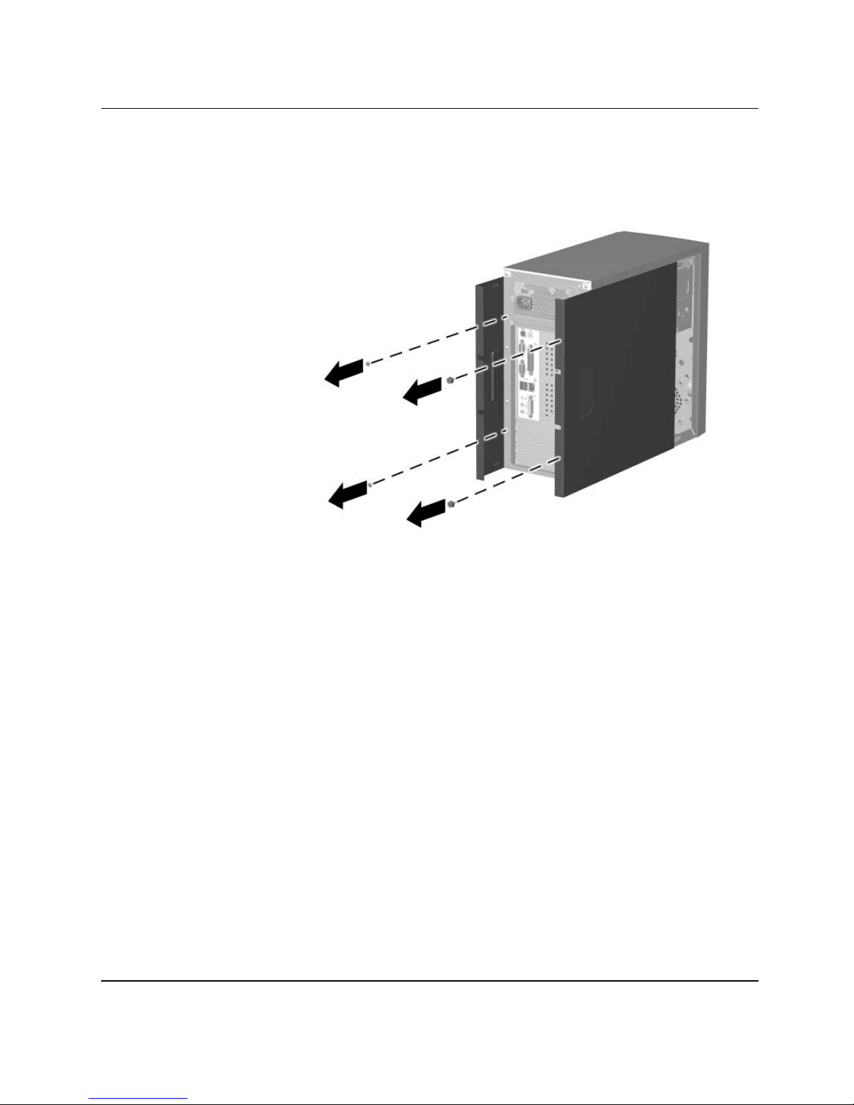
4. Squeeze the two circular tabs inside the front of the chassis 1,
then pull the front bezel away from the chassis to release it 2.
Removing the Front Bezel
✎
1–4 Hardware Reference Guide
When replacing the front bezel, ensure that the circular tabs are
properly aligned with the chassis before pressing the front bezel into
place.
Page 8

Installing Additional Memory
CAUTION: Your memory module sockets have gold metal contacts.
Ä
Ä
Ä
When upgrading your memory, it is important to use memory modules
with gold metal contacts to prevent corrosion and/or oxidation resulting
from having incompatible metals in contact with each other.
CAUTION: Static electricity can damage the electronic components of
the computer or optional cards. Before beginning these procedures,
ensure that you are discharged of static electricity by briefly touching a
grounded metal object. Refer to Chapter 4, “Electrostatic Discharge,” for
more information.
CAUTION: When handling a memory module, be careful not to touch
any of the contacts. Doing so may damage the module.
1. Shut down the operating system properly, then turn off the
computer and any external devices.
Hardware Upgrades
Å
2. Disconnect the power cord from the power outlet, and disconnect
any external devices.
3. Remove the access panel and locate the memory module sockets.
WARNING: To reduce risk of personal injury from hot surfaces, allow
the internal system components to cool before touching.
Hardware Reference Guide 1–5
Page 9

Hardware Upgrades
4. Open both latches of the memory module socket 1, and insert the
memory module into the socket 2.
Installing a Memory Module
5. Begin by installing a module into the socket nearest the
preinstalled module, and install the modules following the
numerical order of the sockets.
6. A memory module can be installed in only one way. Match the
notch on the module with the tab on the memory socket. Push the
module down into the socket, ensuring that the module is fully
inserted and the latches on each end snap back into place 3.
7. Repeat steps 4 to 6 for any additional modules that you want to
install.
8. Replace the access panel.
The computer should automatically recognize the additional memory
the next time you turn on the computer.
1–6 Hardware Reference Guide
Page 10

Hardware Upgrades
Installing or Removing an Expansion Card
1. Shut down the operating system properly, then turn off the
computer and any external devices.
2. Disconnect the power cord from the power outlet, and disconnect
any external devices.
3. Remove the access panel.
If installing an expansion card, skip to step 8.
4. To remove an expansion card, disconnect any cables attached to
the expansion card.
5. Remove the screw at the top of the expansion slot.
6. Hold the card at each end and carefully rock it back and forth
until the connectors pull free from the socket. Be sure not to
scrape the card against other components.
7. Store the card in anti-static packaging.
8. Install a new expansion card or an expansion slot cover to close
the open slot.
If not installing an additional expansion card, skip to step 10.
9. Remove the expansion slot cover.
Hardware Reference Guide 1–7
Page 11
Hardware Upgrades
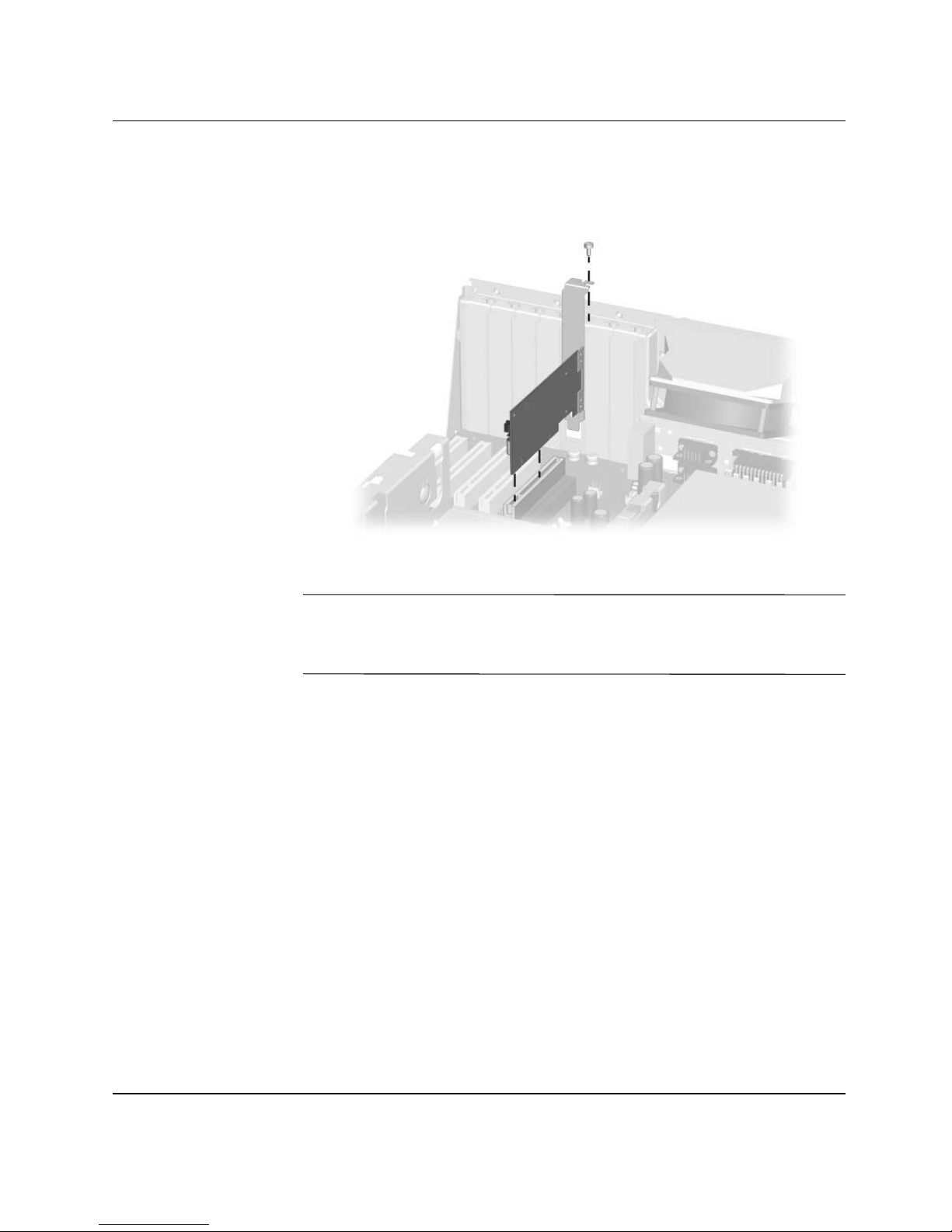
10. Slide the expansion card into the expansion socket and press it
firmly into place.
✎
Installing an Expansion Card
When you install an expansion card, make sure you press firmly on
the card so that the entire connector seats properly in the expansion
card socket.
11. Replace the screw at the top of the expansion slot.
12. Replace the access panel.
13. Connect external cables to the installed card, if needed.
Reconfigure the computer, if necessary.
1–8 Hardware Reference Guide
Page 12

Removing a 5.25 Inch Drive
1. Shut down the operating system properly, then turn off the
computer and any external devices.
2. Disconnect the power cord from the power outlet.
3. Remove both access panels.
4. Remove the front bezel.
5. Disconnect the power, data, and audio cables, as necessary, from
the back of the drive.
6. Remove the four screws, two from each side, that secure the drive
in the drive cage 1.
7. Slide the drive out of the drive cage, as shown in the illustration
below 2.
Hardware Upgrades
Removing the 5.25 Inch Drive
Hardware Reference Guide 1–9
Page 13

Hardware Upgrades
Removing a Diskette Drive or Hard Drive
1. Shut down the operating system properly, then turn off the
computer and any external devices.
2. Disconnect the power cord from the power outlet.
3. Remove the left access panel.
4. Remove the front bezel.
5. Disconnect the power, data, and audio cables, as necessary, from
the back of the drive.
6. Remove the four screws, 3 in the front and 1 on the side, that
secure the drive cage to the chassis.
Removing the Drive Cage
7. Remove the drive cage from the chassis.
1–10 Hardware Reference Guide
Page 14

Hardware Upgrades
8. Remove the four screws, two from each side, that secure the drive
in the drive cage 1.
9. Slide the drive out of the drive cage, as shown in the illustrations
below 2.
Removing the Diskette Drive
Removing the Hard Drive
To replace the drive cage, reverse steps 5-6.
Hardware Reference Guide 1–11
Page 15

Replacing the Battery
The battery that comes with your computer provides power to the
real-time clock and has a lifetime of about three years. When
replacing the battery, use an equivalent 3-volt lithium coin cell
battery. A replacement battery may be purchased at your local retailer
or from the
Compaq.com Web site.
2
Battery Replacement
✎
Å
The spare part number for a standard coin cell battery is 153099-001,
which corresponds to a CR2032 battery or equivalent.
WARNING: Your computer contains an internal lithium manganese dioxide,
vanadium pentoxide, or alkaline battery or battery pack. There is a risk of fire
and burns if the battery pack is not handled properly. To reduce the risk of
personal injury:
■ Do not expose the battery to temperatures higher than
140° F (60° C).
■ Do not disassemble, crush, puncture, short external contacts, or
dispose of the battery in fire or water.
■ Replace the battery only with the Compaq spare designated for this
product.
■ Do not attempt to recharge the battery.
Hardware Reference Guide 2–1
Page 16
Battery Replacement
Ä
N
CAUTION: Static electricity can damage the electronic components of
the workstation or optional equipment. Before beginning these
procedures, ensure that you are discharged of static electricity by briefly
touching a grounded metal object.
Batteries, battery packs, and accumulators should not be disposed of
together with the general household waste. To forward them to recycling
or proper disposal, please use the public collection system or return them
to Compaq, your authorized partners, or their agents.
To replace the battery:
1. Shut down the operating system properly, turn off the computer
and any external devices, disconnect the power cord from the
electrical outlet, and remove the computer cover or access panel.
✎
It may be necessary to remove an expansion card to gain access to the
battery.
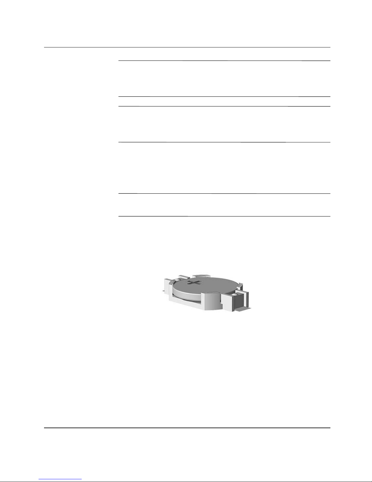
2. Locate the battery and battery holder on the system board, as
shown in the following illustration.
3. Press the release latch to remove the battery.
Battery and Battery Holder
2–2 Hardware Reference Guide
Page 17
Battery Replacement
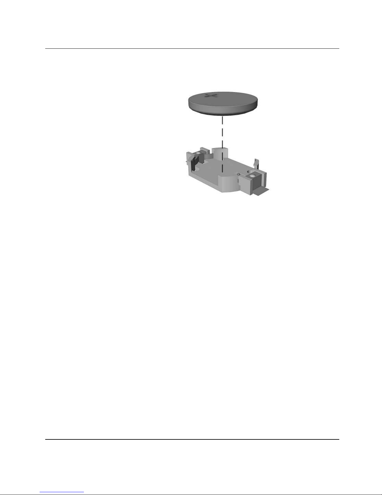
4. Lift the battery out of its holder.
Removing the Coin Cell Battery
5. Slide the replacement battery into position, positive side up. The
battery holder automatically secures the battery in the proper
position.
6. Replace any expansion boards you removed.
7. Replace the computer cover or access panel.
8. Plug in and turn on the computer.
9. Reset the date and time, your passwords, and any special system
setups, using Computer Setup. Refer to the Computer Setup (F10)
Utility Guide for additional information.
Hardware Reference Guide 2–3
Page 18

Routine Care & Shipping Information
Routine Care
3
Follow these suggestions to take care of your personal computer and
monitor:
■ Operate the personal computer on a sturdy, level surface. Leave a
3-inch (7.6-cm) clearance at the back of the system unit and
above the monitor to permit the required airflow.
■ Never operate the personal computer with the cover or side panel
removed.
■ Never restrict the airflow into the personal computer by blocking
the air intake or exhaust vents.
■ Keep the personal computer away from excessive moisture, direct
sunlight, and extremes of heat and cold.
■ Keep liquids away from the personal computer and keyboard.
■ Never cover the ventilation slots on the monitor with any type of
material.
■ Turn off the personal computer before you do either of the
following:
❏ Wipe the exterior of the personal computer with a soft, damp
cloth as needed. Using cleaning products may discolor or
damage the finish.
❏ Occasionally clean the air intake and exhaust vents on the
personal computer. Lint and other foreign matter can block
the vents and limit the airflow.
Hardware Reference Guide 3–1
Page 19

Routine Care & Shipping Information
CD-ROM Drive Precautions
Be sure to observe the following guidelines while operating or
cleaning your CD-ROM drive.
Operation
■ Do not move the drive during operation. This may cause it to
malfunction during reading.
■ Avoid exposing the drive to sudden changes in temperature, as
condensation may form inside the unit. If the temperature
suddenly changes while the drive is on, wait at least one hour
before you turn off the power. If you operate the unit
immediately, it may malfunction while reading.
■ Avoid placing the drive in a location that is subject to high
humidity, extreme temperatures, mechanical vibration, or direct
sunlight.
Cleaning
Safety
■ Clean the panel and controls with a soft, dry cloth or a soft cloth
lightly moistened with a mild detergent solution. Never spray
cleaning fluids directly on the unit.
■ Avoid using any type of solvent, such as alcohol or benzene,
which may damage the finish.
If any object or liquid falls into the drive, immediately unplug the
personal computer and have it checked by an authorized Compaq
service provider.
3–2 Hardware Reference Guide
Page 20

Shipping Preparation
Follow these suggestions when preparing to ship your personal
computer:
1. Back up the hard drive files onto the network or removable
media. Be sure that the backup media is not exposed to electrical
or magnetic impulses while stored or in transit.
Routine Care & Shipping Information
✎
The hard drive locks automatically when the system power is turned
off.
2. Remove and store separately any removable media and MultiBay
drives.
3. Turn off the personal computer and external devices.
4. Disconnect the power cord from the electrical outlet, then from
the personal computer.
5. Pack the system components, MultiBay drives, and external
devices in their original packing boxes or similar packaging with
sufficient packing material to protect them.
Hardware Reference Guide 3–3
Page 21

Electrostatic Discharge
A discharge of static electricity from a finger or other conductor may
damage system boards or other static-sensitive devices. This type of
damage may reduce the life expectancy of the device.
Preventing Electrostatic Damage
To prevent electrostatic damage, observe the following precautions:
■ Avoid hand contact by transporting and storing products in
static-safe containers.
■ Keep electrostatic-sensitive parts in their containers until they
arrive at static-free workstations.
■ Place parts on a grounded surface before removing them from
their containers.
4
■ Avoid touching pins, leads, or circuitry.
■ Always be properly grounded when touching a static-sensitive
component or assembly.
Hardware Reference Guide 4–1
Page 22

Electrostatic Discharge
Grounding Methods
There are several methods for grounding. Use one or more of the
following methods when handling or installing electrostatic-sensitive
parts:
■ Use a wrist strap connected by a ground cord to a grounded
workstation or computer chassis. Wrist straps are flexible straps
with a minimum of 1 Megaohm +/- 10 percent resistance in the
ground cords. To provide proper ground, wear the strap snug
against the skin.
■ Use heelstraps, toestraps, or bootstraps at standing workstations.
Wear the straps on both feet when standing on conductive floors
or dissipating floor mats.
■ Use conductive field service tools.
■ Use a portable field service kit with a folding static-dissipating
work mat.
✎
If you do not have any of the suggested equipment for proper
grounding, contact your Compaq authorized dealer, reseller, or
service provider.
For more information on static electricity, contact your Compaq
authorized dealer, reseller, or service provider.
4–2 Hardware Reference Guide
Page 23

Index
A
access panels
removing
1–2
B
battery replacement
battery disposal
procedure
risk of fire (warning)
spare part number for coin cell
static electricity (caution)
2–2
2–2
2–1
C
care of equipment 3–1
cautions
battery replacement/disposal
handling memory modules
incompatible metals (RAM)
removing access panels
static electricity
static electricity (RAM)
CD-ROM drive
cleaning and safety
1–1
3–2
2–2
1–2
1–5
2–2
1–5
1–5
2–1
F
front bezel
removing
1–4
I
installation sequence 1–1
installing
an expansion card
1–7
M
memory
hot surfaces (warning)
incompatible metals (caution)
installation procedure
static electricity (caution)
1–5
1–5
1–5
P
packaging guidelines 3–3
R
removing
access panels
an expansion card
removing access panels (caution)
1–2
1–7
1–5
1–2
D
drives
removing 5.25" (optical) drive
removing diskette drive
removing hard drive
1–10
E
electrostatic discharge
grounding methods
preventing damage
Hardware Reference Guide Index–1
4–2
4–1
1–10
1–9
S
shipping guidelines 3–3
W
warnings
battery replacement
electrical shock
hot surfaces
1–1
1–5
2–1
 Loading...