

Compaq 4354R - StorageWorks Enclosure Storage, StorageWorks 4300, MA8000, EMA12000 Addendum
Page 1

Model 4300 Family Ultra3 LVD Disk Enclosure
Addendum for Use with the MA8000/EMA12000
Storage System
This document summarizes features and characteristics of using the Model 4310R, Model 4350R,
Model 4314R, and Model 4354R disk enclosures in an MA8000/EMA12000 Storage System,
running ACS version 8.5.
Compaq StorageWorks™
First Edition (August 2000)
Part Number: EK-U3LVD-AA. A01
Compaq Computer Corporation
Page 2

2 Compaq StorageWorks Model 4300 Family Ultra3 LVD Disk Enclosure
© 2000 Compaq Compute r Corporation.
COMPAQ, the Compaq logo and StorageWorks are registered in U.S. Patent and Trademark
Office.
All othe r product nam es mentioned herein may be trademarks or registered trademarks of their
respective companies.
Compaq shall not be liab le for techni cal or editorial errors or omissions contained herei n. The
information in this document is subject to change without notice.
THE INFORMATION IN THIS PUBLICATI ON IS PROVIDED “AS IS” WITHOUT
WARRANTY OF ANY KIND. THE ENTIRE RISK ARISING OUT OF THE USE OF THIS
INFORMATION REMAINS WITH RECIPIENT. IN NO EVENT SHALL COMPAQ BE
LIABLE FOR ANY DIRECT, CONSEQUENTIAL, INCIDENTAL, SPECIAL, PUNITIVE
OR OTHER D AMAGES WHATSOEVER (INCLUDING WITHOUT LIMITATION,
DAMAGES FOR LOSS OF BUSINESS PROFITS, BUSINESS INTERRUPTION OR LOSS
OF BUSINESS INFORMATION), EVEN IF COMPAQ HAS BEEN ADVISED OF THE
POSSIBILITY OF SUCH DAMAGES AND WHETHER IN AN ACTION OF CONTRACT
OR TOR T, INCLUDING NEGLIGENCE.
The limit ed w arranties for Compaq products are exclusiv ely set forth in the
documentat ion accompanying such products. Nothing herein should be construed as
constituting a fur ther or additional warranty.
Printed in the U.S.A.
Page 3

Addendum for Use with the MA8000/EMA12000 Storage System 3
Disk Enclosures
The Model 4300 family of Ultra3 SCSI disk enclosures is made up of four models:
■ Model 4310R disk enclosure - 10 drive bays , single-bus I/O module.
■ Model 4350R disk enclosure - 10 drive bays , dual-bus I/O module.
Figure 1 shows the drive enclosure bay numbering for Models 4310R and 4350R.
Figure 1. Model 4310R and 4350R 10-Drive Enclosure Bay Numbering
■
Model 4314R disk enclosure - 14 drive bays , single-bus I/O module.
■ Model 4354R disk enclosure - 14 drive bays , dual-bus I/O module.
Figure 2 shows the drive enclosure bay numbering for Models 431 4R and 4354R.
Figure 2. Model 4314R and 4354R 14-Drive Enclosure Bay Numbering
CXO7381A
2
3
4
5
6
7
8
9
1
10
CXO7380A
9
8
7
6
5
4
3
2
1
10
11
12
13
14
Page 4
4 Compaq StorageWorks Model 4300 Family Ultra3 LVD Disk Enclosure
MA8000/EMA12000 Storage System
Installation
WARNING: A shock hazard exists at the backplane when the controller enclosure
bays or cache module bays are empty.
Be sure the enclosures are empty, then mount the enclosures into the rack. DO NOT
use the disk enclosure handles to lift the enclosure. The handles cannot support the
weight of the enclosure. Only use these handles to position the enclosure in the
mounting brackets.
Use two people to lift, align, and install any enclosure into a rack. Failure to use two
people might cause personal injury and/or equipment damage.
CAUTION: Controller and disk enclosures have no power switches. Make sure the
controller enclosures and disk enclosures are physically configured before turning the
PDU on and connecting the power cords. Failure to do so can cause equipment
damage.
1. Be sure the enclosures are empty before mounting them into the rack. If necessary,
remove the following elements from the controller e n closure:
❏ Environmental Moni toring Unit (EMU) ❏ Power Supplies
❏ External Cache Batteries (ECBs) ❏ Fans
If necessary, remove the following elements from the disk enclosure:
❏ Power Supply/Blower Assemblies ❏ Disk Drives
❏ Environmental Moni toring Unit (EMU) ❏ I/O Modules
Refer to the Compaq StorageWorks Model 2100 and 2200 UltraSCSI Controller User
Guide, Compaq StorageWorks Enclosure 4200 Family LVD Disk Enclosure User
Guide, and Compaq StorageWorks Enclosure 4300 Family LVD Disk Enclosur e User
Guide the for further inform ation.
2. Install brackets onto the controller enclosu re and disk enclosures. Us ing two people,
mount the enclosures into the rack. Refer to the mounting kit documentation for
further information.
3. Install the elements. Install the disk drives (up to 12 disk drives in the Mode l 4314R
disk enclosure s , or up to 14 dis k drives in the Model 4354R disk enclosu r es). Make
sure you install blank panels in any unus ed bays.
Page 5
Addendum for Use with the MA8000/EMA12000 Storage System 5
NOTE: Fibre channel cabling information is shown to illustrate supported configurations. In a
dual-bus disk enclosure configuration, disk enclosures 1, 2, and 3 are stacked below the
controller enclosure—two SCSI Buses per enclosure
(see Figure 3). In a single-bus disk
enclosure configuration, disk enclosures 6, 5, and 4 are stacked above the controller enclosure
and disk enclosures 1, 2, and 3 are stacked below the controller enclosure—one SCSI Bus per
enclosure(see Figure 4).
4. Connect the six VHDCI UltraSCSI bus cabl es between the controller and disk
enclosures as shown in Figure 3 for a dual bus system and Figure 4 for a single bus
system. Note that the maximum supported cable le ngths are 1, 2, 3, 5, and 10 mete rs .
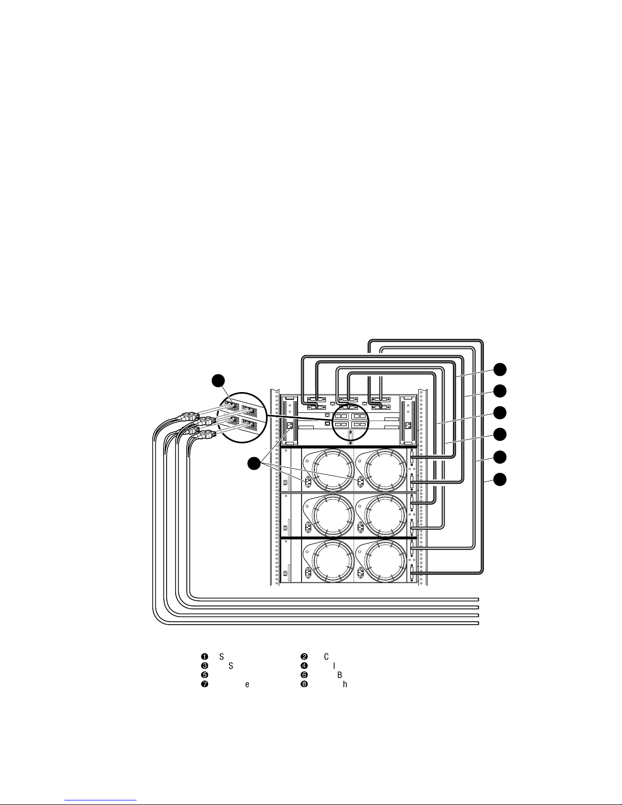
Figure 3. Dual-Bus MA8000/EMA12000 Storage System
1
SCSI Bus 1 Cable
2
SCSI Bus 2 Cable
3
SCSI Bus 3 Cable
4
SCSI Bus 4 Cable
5
SCSI Bus 5 Cable
6
SCSI Bus 6 Cable
7
AC Power Inputs
8
Fibre Channel Ports
1
3
2
5
6
4
7
8
CXO7383A
Page 6
6 Compaq StorageWorks Model 4300 Family Ultra3 LVD Disk Enclosure
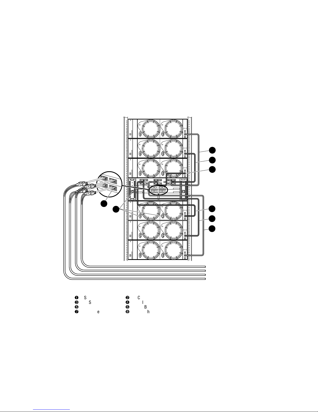
Figure 4. Single-Bus MA8000/EMA12000 Storage System
5. Connect the A C power cords from the appropriate rac k AC outl ets to the c ontroll er and
disk enclosures.
1
SCSI Bus 1 Cable
2
SCSI Bus 2 Cable
3
SCSI Bus 3 Cable
4
SCSI Bus 4 Cable
5
SCSI Bus 5 Cable
6
SCSI Bus 6 Cable
7
AC Power Inputs
8
Fibre Channel Ports
1
8
2
3
6
CXO7382A
4
5
7
Page 7

Addendum for Use with the MA8000/EMA12000 Storage System 7
Creating Storage Maps
The controller can operate either in a BA370 enclosure or in a Model 2200 controller
enclosure.
The Model 2200 contr oller enclosure can be combined with the following:
■ Model 4214R disk enclosure - Ultra2 S CSI with 14 drive bays, single-bus I/O
module.
■ Model 4254 disk enclosure - Ultra2 SCSI with 14 drive bays, dual-bus I/O module.
NOTE: The Model 4214R uses the same storagemaps as the Model 4314R and the Model 4254
uses the same storage maps as the Model 4354R disk enclosures.
■
Model 4310R disk enclosure - Ultra3 S CSI with 10 drive bays, single-bus I/O
module. Figure 5 show s the addresses for each device in a six-shelf sing le-bus
config uration . A maximum of six Model 4310R disk enc losur es can be used with each
Model 2200 controller enclosure.
NOTE: The storage map for the Model 4310R reflects the disk enclosures physical location in
the rack. Disk enclosures 6, 5, and 4 are stacked above the controller enclosure and disk
enclosures 1, 2, and 3 are stacked below the controller enclosure.
■
Model 4350R disk enclosure - Ultra3 SCSI with 10 drive bays, dual-bus I/O module.
Figure 6 shows th e address es for each de vic e in a three- shelf dual-b us confi gurati on. A
maximum of three Model 4350R disk enclosur es can be used with each Model 2200
controller enclosu re.
■ Model 4314R disk enclosure - Ultra3 S CSI with 14 drive bays, single-bus I/O
module. Figure 7 show s the addresses for each device in a six-shelf sing le-bus
config uration . A maximum of six Model 4314R disk enc losur es can be used with each
Model 2200 controller enclosure.
NOTE: The storage map for the Model 4314R reflects the disk enclosures physical location in
the rack. Disk enclosures 6, 5, and 4 are stacked above the controller enclosure and disk
enclosures 1, 2, and 3 are stacked below the controller enclosure.
■
Model 4354R disk enclosure - Ultra3 SCSI with 14 drive bays, dual-bus I/O module.
Figure 8 shows th e address es for each de vic e in a three- shelf dual-b us confi gurati on. A
maximum of three Model 4354R disk enclosur es can be used with each Model 2200
controller enclosu re.
Page 8
8 Compaq StorageWorks Model 4300 Family Ultra3 LVD Disk Enclosure
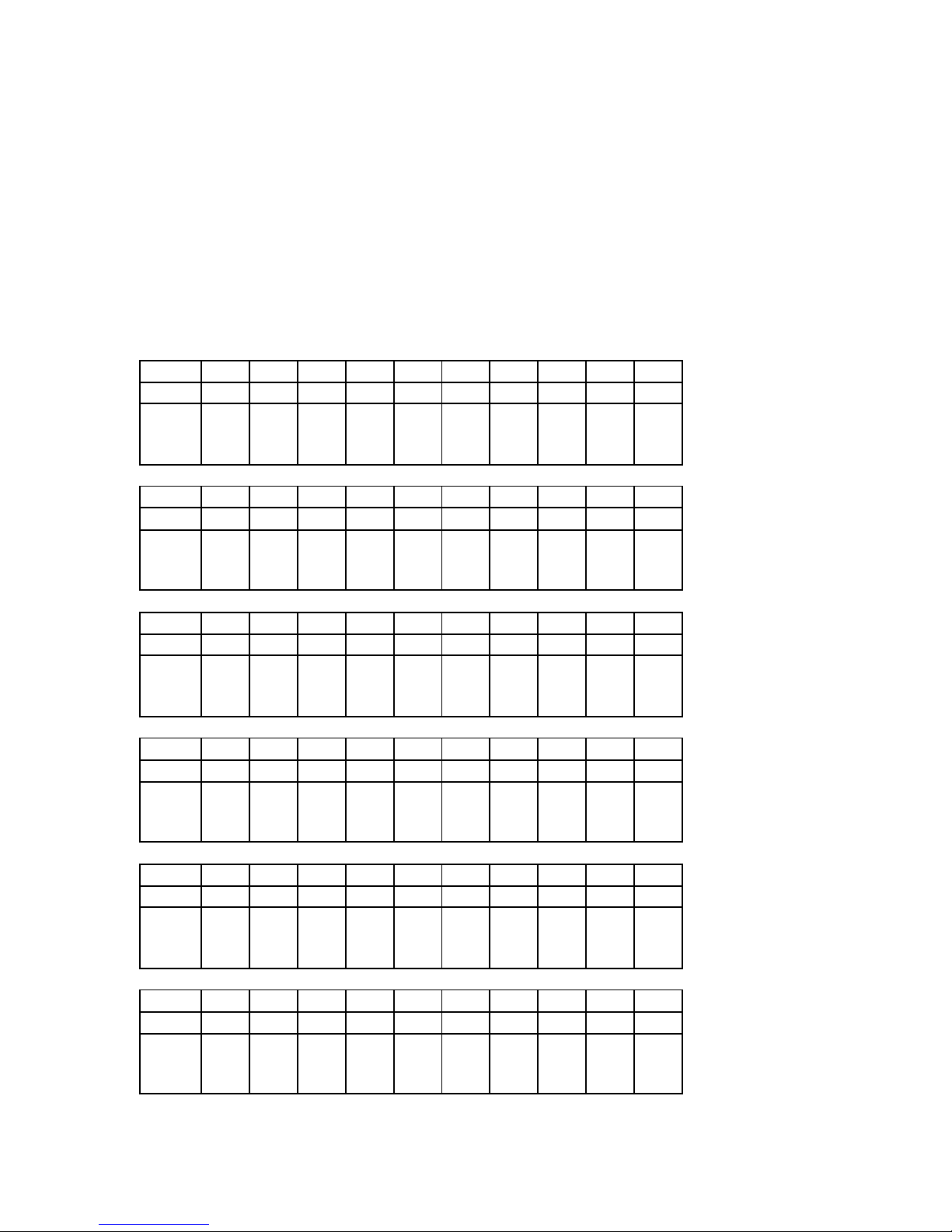
Figure 5. PTL addressing in a single-bus configuration, using six Model 4310R disk enclosures
Model 4310R Disk Enclosure Shelf 6 (single-bus)
Bay12345678910
SCSI ID 00 01 02 03 04 05 08 10 11 12
DISK ID
Disk60000
Disk60100
Disk60200
Disk60300
Disk60400
Disk60500
Disk60800
Disk61000
Disk61100
Disk61200
Model 4310R Disk Enclosure Shelf 5 (single-bus)
Bay12345678910
SCSI ID 00 01 02 03 04 05 08 10 11 12
DISK ID
Disk50000
Disk50100
Disk50200
Disk50300
Disk50400
Disk50500
Disk50800
Disk51000
Disk51100
Disk51200
Model 4310R Disk Enclosure Shelf 4 (single-bus)
Bay12345678910
SCSI ID 00 01 02 03 04 05 08 10 11 12
DISK ID
Disk40000
Disk40100
Disk40200
Disk40300
Disk40400
Disk40500
Disk40800
Disk41000
Disk41100
Disk41200
Model 4310R Disk Enclosure Shelf 1 (single-bus)
Bay12345678910
SCSI ID 00 01 02 03 04 05 08 10 11 12
DISK ID
Disk10000
Disk10100
Disk10200
Disk10300
Disk10400
Disk10500
Disk10800
Disk11000
Disk11100
Disk11200
Model 4310R Disk Enclosure Shelf 2 (single-bus)
Bay12345678910
SCSI ID 00 01 02 03 04 05 08 10 11 12
DISK ID
Disk20000
Disk20100
Disk20200
Disk20300
Disk20400
Disk20500
Disk20800
Disk21000
Disk21100
Disk21200
Model 4310R Disk Enclosure Shelf 3 (single-bus)
Bay12345678910
SCSI ID 00 01 02 03 04 05 08 10 11 12
DISK ID
Disk30000
Disk30100
Disk30200
Disk30300
Disk30400
Disk30500
Disk30800
Disk31000
Disk31100
Disk31200
Page 9
Addendum for Use with the MA8000/EMA12000 Storage System 9
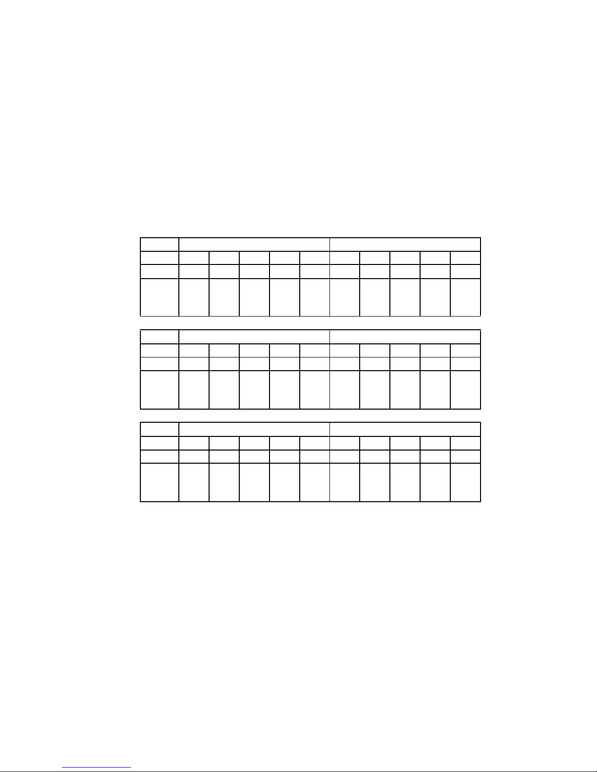
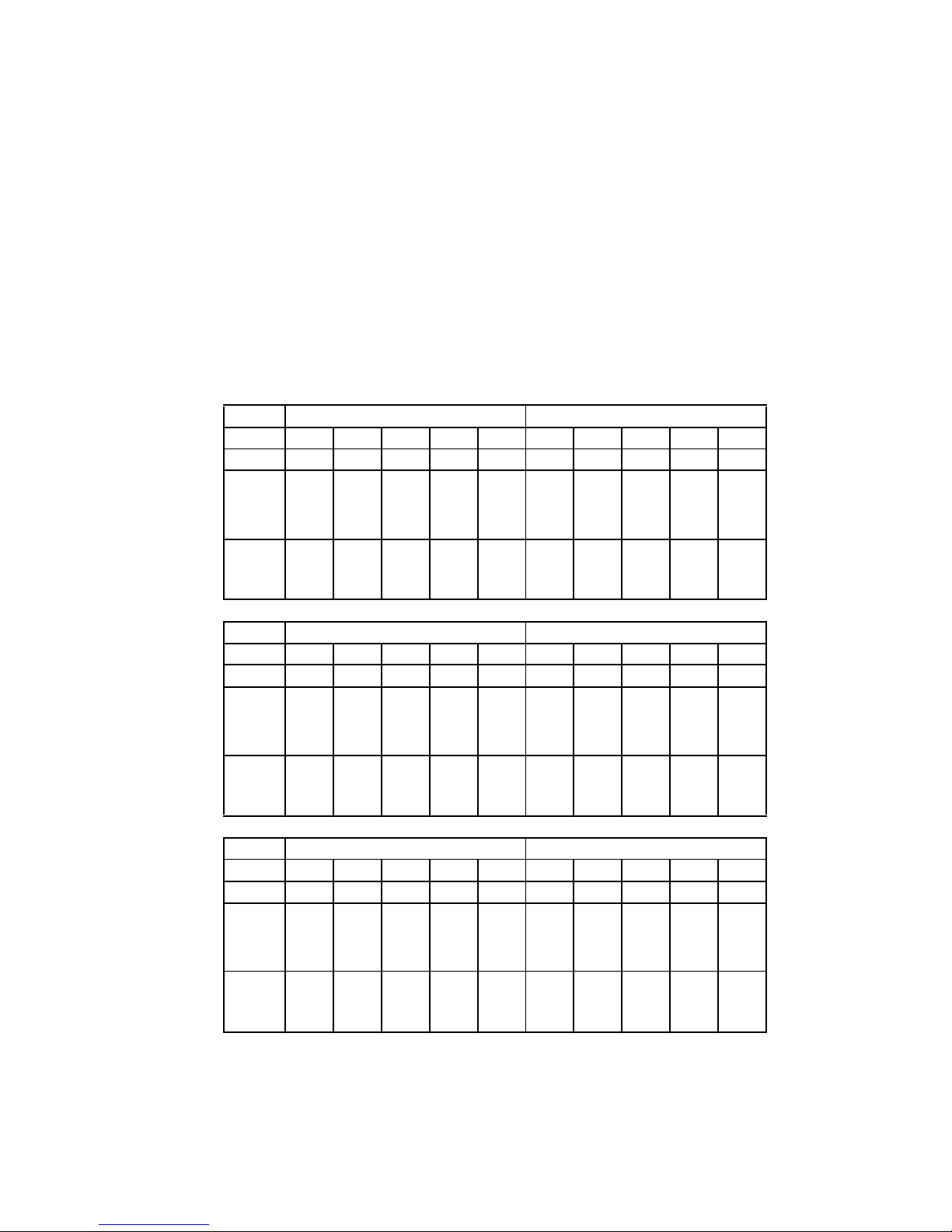
Figure 6. PTL addressing in a dual-bus configuration, using three Model 4350R disk enclosures
Model 4350R Disk Enclosure Shelf 1 (dual-bus)
SCSI Bus A SCSI Bus B
Bay 12345678910
SCSI ID 00 01 02 03 04 00 01 02 03 04
DISK ID
Disk10000
Disk10100
Disk10200
Disk10300
Disk10400
Disk20000
Disk20100
Disk20200
Disk20300
Disk20400
Model 4350R Disk Enclosure Shelf 2 (dual-bus)
SCSI Bus A SCSI Bus B
Bay 12345678910
SCSI ID 00 01 02 03 04 00 01 02 03 04
DISK ID
Disk30000
Disk30100
Disk30200
Disk30300
Disk30400
Disk40000
Disk40100
Disk40200
Disk40300
Disk40400
Model 4350R Disk Enclosure Shelf 3 (dual-bus)
SCSI Bus A SCSI Bus B
Bay 12345678910
SCSI ID 00 01 02 03 04 00 01 02 03 04
DISK ID
Disk50000
Disk50100
Disk50200
Disk50300
Disk50400
Disk60000
Disk60100
Disk60200
Disk60300
Disk60400
Page 10

10 Compaq StorageWorks Model 4300 Family Ultra3 LVD Disk Enclosure
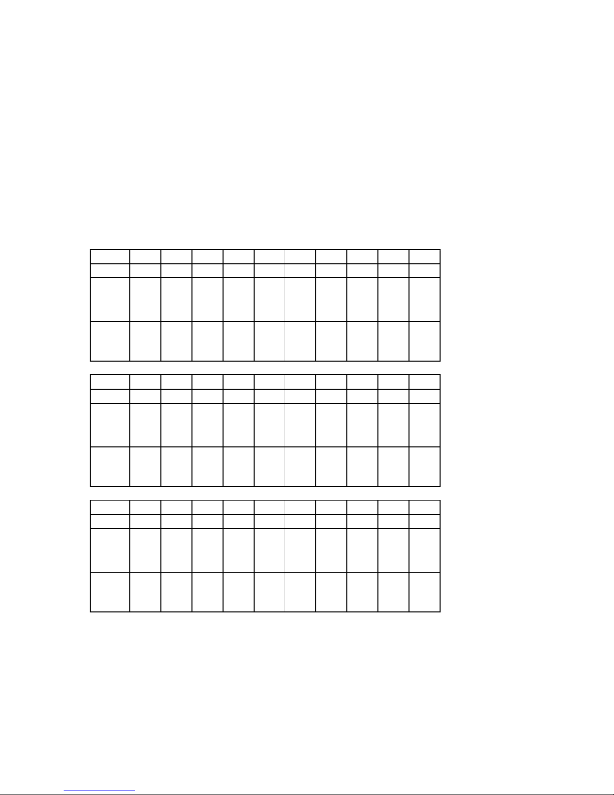
Figure 7. PTL addressing in a single-bus configuration, using six Model 4314R disk enclosures
Model 4314R Disk Enclosure Shelf 6 (single-bus)
Bay 1234567891011121314
SCSI ID 00 01 02 03 04 05 08 09 10 11 12 13 14 15
DISK ID
Disk60000
Disk60100
Disk60200
Disk60300
Disk60400
Disk60500
Disk60800
Disk60900
Disk61000
Disk61100
Disk61200
Disk61300
not
supported
not
supported
Model 4314R Disk Enclosure Shelf 5 (single-bus)
Bay 1234567891011121314
SCSI ID 00 01 02 03 04 05 08 09 10 11 12 13 14 15
DISK ID
Disk50000
Disk50100
Disk50200
Disk50300
Disk50400
Disk50500
Disk50800
Disk50900
Disk51000
Disk51100
Disk51200
Disk51300
not
supported
not
supported
Model 4314R Disk Enclosure Shelf 4 (single-bus)
Bay 1234567891011121314
SCSI ID 00 01 02 03 04 05 08 09 10 11 12 13 14 15
DISK ID
Disk40000
Disk40100
Disk40200
Disk40300
Disk40400
Disk40500
Disk40800
Disk40900
Disk41000
Disk41100
Disk41200
Disk41300
not
supported
not
supported
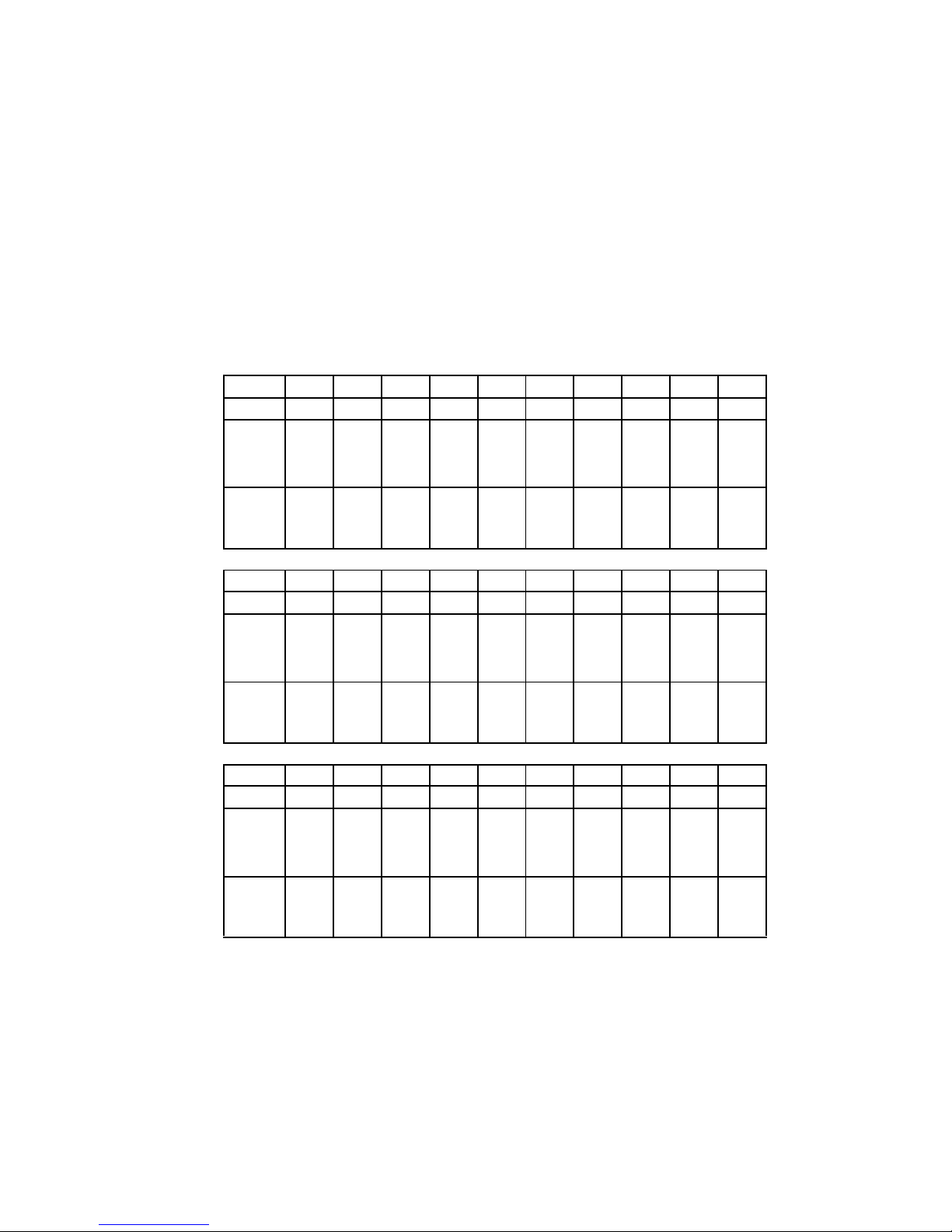
Model 4314R Disk Enclosure Shelf 1 (single-bus)
Bay 1234567891011121314
SCSI ID 00 01 02 03 04 05 08 09 10 11 12 13 14 15
DISK ID
Disk10000
Disk10100
Disk10200
Disk10300
Disk10400
Disk10500
Disk10800
Disk10900
Disk11000
Disk11100
Disk11200
Disk11300
not
supported
not
supported
Model 4314R Disk Enclosure Shelf 2 (single-bus)
Bay 1234567891011121314
SCSI ID 00 01 02 03 04 05 08 09 10 11 12 13 14 15
DISK ID
Disk20000
Disk20100
Disk20200
Disk20300
Disk20400
Disk20500
Disk20800
Disk20900
Disk21000
Disk21100
Disk21200
Disk21300
not
supported
not
supported
Model 4314R Disk Enclosure Shelf 3 (single-bus)
Bay 1234567891011121314
SCSI ID 00 01 02 03 04 05 08 09 10 11 12 13 14 15
DISK ID
Disk30000
Disk30100
Disk30200
Disk30300
Disk30400
Disk30500
Disk30800
Disk30900
Disk31000
Disk31100
Disk31200
Disk31300
not
supported
not
supported
Page 11

Addendum for Use with the MA8000/EMA12000 Storage System 11
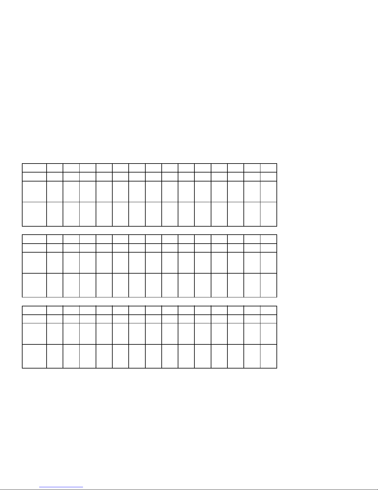
Figure 8. PTL addressing in a dual-bus configuration, using three Model 4354R disk enclosures
Model 4354R Disk Enclosure Shelf 1 (dual-bus)
SCSI Bus A SCSI Bus B
Bay 1234567891011121314
SCSI ID 00 01 02 03 04 05 08 00 01 02 03 04 05 08
DISK ID
Disk10000
Disk10100
Disk10200
Disk10300
Disk10400
Disk10500
Disk10800
Disk20000
Disk20100
Disk20200
Disk20300
Disk20400
Disk20500
Disk20800
Model 4354R Disk Enclosure Shelf 2 (dual-bus)
SCSI Bus A SCSI Bus B
Bay 1234567891011121314
SCSI ID 00 01 02 03 04 05 08 00 01 02 03 04 05 08
DISK ID
Disk30000
Disk30100
Disk30200
Disk30300
Disk30400
Disk30500
Disk30800
Disk40000
Disk40100
Disk40200
Disk40300
Disk40400
Disk40500
Disk40800
Model 4354R Disk Enclosure Shelf 3 (dual-bus)
SCSI Bus A SCSI Bus B
Bay 1234567891011121314
SCSI ID 00 01 02 03 04 05 08 00 01 02 03 04 05 08
DISK ID
Disk50000
Disk50100
Disk50200
Disk50300
Disk50400
Disk50500
Disk50800
Disk60000
Disk60100
Disk60200
Disk60300
Disk60400
Disk60500
Disk60800
Page 12

12 Compaq StorageWorks Model 4300 Family Ultra3 LVD Disk Enclosure
Example Storage Maps for the HSG80
Example Storage Map - Model 4310R Disk Enclosure
Figure 9 shows an example of four Model 4310R disk enc los ures (single-bus I/O).
■ Unit D100 is a 4-member RAID 3/5 storageset named R1. R1 consists of Disk10000,
Disk20000, Disk30000, and Disk 40000.
■ Unit D101 is a 2-member str iped mirrorset named S1. S1 con si sts of M1 and M2:
❏ M1 is a 2-member mirrorset cons is ting of Disk10100 and Disk20100.
❏ M2 is a 2-member mirrorset cons is ting of Disk30100 and Disk40100.
■ Unit D102 is a 2-member mirrorset na me d M3. M3 con si sts of Disk10200 and
Disk20200.
■ Unit D103 is a 2-member mirrorset na me d M4. M4 con si sts of Disk30200 and
Disk40200.
■ Unit D104 is 3-member stri peset n amed S2. S2 consi sts of Dis k10300, Disk20 300, and
Disk30300.
■ Unit D105 is a single (JBOD) disk named Disk40300.
■ Unit D106 is a 3-member RAID 3/5 storageset named R2. R2 consists of Disk10400,
Disk20400, and Disk30400.
■ Unit D107 is a single (JBOD) disk named Disk40400.
■ Unit D108 is a 4-member stripeset named S3. S3 consists of Disk10500, Disk20500,
Disk30500, and Disk40500.
■ Unit D1 is a 2-member striped mirro rset named S4. S4 consists of M4 and M5:
❏ M4 is a 2-member mirrorset cons is ting of Disk10800 and Disk20800.
❏ M5 is a 2-member mirrorset cons is ting of Disk30800 and Disk40800.
■ Unit D2 is a 4-member RAID 3/5 stor ageset named R3. R3 consists of Disk11000,
Disk21000, Disk31000, and Disk41000.
■ Unit D3 is a 4-member stripeset named S5. S5 consists of Disk11100, Disk21100,
Disk31100, and Disk41100.
■ Unit D4 is a 2-member mirrorset named M7. M7 consists of Disk11200 and
Disk21200.
■ Disk31200 and Disk41200 are spareset members.
Page 13

Addendum for Use with the MA8000/EMA12000 Storage System 13
Figure 9. Model 4310R disk enclosure - example storage map
Model 4310R Disk Enclosure Shelf 4 (single-bus)
Bay12345678910
SCSI ID 00 01 02 03 04 05 08 10 11 12
D100
R1
D101
S1
M2
D103
M4
D105 D107
D108
S3
D1
S4
M6
D2
R3
D3
S5
spare
DISK ID
Disk40000
Disk40100
Disk40200
Disk40300
Disk40400
Disk40500
Disk40800
Disk41000
Disk41100
Disk41200
Model 4310R Disk Enclosure Shelf 1 (single-bus)
Bay12345678910
SCSI ID 00 01 02 03 04 05 08 10 11 12
D100
R1
D101
S1
M1
D102M3D104S2D106R2D108
S3
D1
S4
M5
D2
R3
D3
S5
D4
M7
DISK ID
Disk10000
Disk10100
Disk10200
Disk10300
Disk10400
Disk10500
Disk10800
Disk11000
Disk11100
Disk11200
Model 4310R Disk Enclosure Shelf 2 (single-bus)
Bay12345678910
SCSI ID 00 01 02 03 04 05 08 10 11 12
D100
R1
D101
S1
M1
D102M3D104S2D106R2D108
S3
D1
S4
M5
D2
R3
D3
S5
D4
M7
DISK ID
Disk20000
Disk20100
Disk20200
Disk20300
Disk20400
Disk20500
Disk20800
Disk21000
Disk21100
Disk21200
Model 4310R Disk Enclosure Shelf 3 (single-bus)
Bay12345678910
SCSI ID 00 01 02 03 04 05 08 10 11 12
D100
R1
D101
S1
M2
D103M4D104S2D106R2D108
S3
D1
S4
M6
D2
R3
D3
S5
spare
DISK ID
Disk30000
Disk30100
Disk30200
Disk30300
Disk30400
Disk30500
Disk30800
Disk31000
Disk31100
Disk31200
Page 14

14 Compaq StorageWorks Model 4300 Family Ultra3 LVD Disk Enclosure
Example Storage Map - Model 4350R Disk Enclosure
Figure 10 shows an example of three Model 4350R disk enclosur es (dual-bus).
■ Unit D100 is a 6-member RAID 3/5 storageset named R1. R1 consists of Disk10000,
Disk20000, Disk30000, Disk 40000, Disk50000, and Disk60000.
■ Unit D101is a 6-member RAID 3/5 stora ges et named R2. R2 consists of Dis k10100,
Disk20100, Disk30100, Disk 40100, Disk50100, and Disk60100.
■ Unit D102 is a 2-member str iped mirrorset named S1. S1 con si sts of M1 and M2:
❏ M1 is a 2-member mirrorset cons is ting of Disk10200 and Disk20200.
❏ M2 is a 2-member mirrorset cons is ting of Disk30200 and Disk40200.
■ Unit D103 is a 2-member mirrorset na me d M3. M3 con si sts of Disk50200 and
Disk60200.
■ Unit D1 is 4-member strip es et named S2. S2 consists of Dis k10300, Disk20300,
Disk30300, and Disk40300.
■ Unit D2 is a 2-member mirrorset named M4. M4 consists of Disk50300 and
Disk60300.
■ Unit D3 is a 2-member striped mirro rset named S3. S3 consists of M5 and M6:
❏ M5 is a 2-member mirrorset cons is ting of Disk10400 and Disk20400.
❏ M6 is a 2-member mirrorset cons is ting of Disk30400 and Disk40400.
■ Unit D4 is a single (JBOD) disk named Disk50400.
■ Disk60400 is a spar eset member .
Page 15
Addendum for Use with the MA8000/EMA12000 Storage System 15
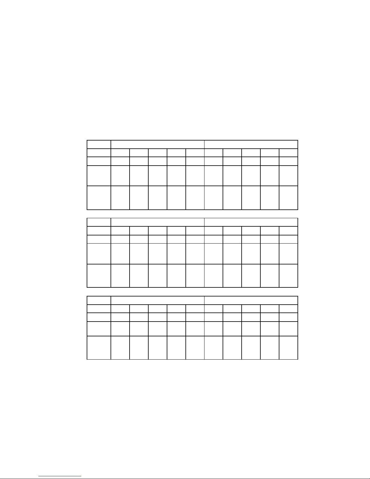
Figure 10. Model 4350R disk enclosure - example storage map
Example Storage Map - Model 4314R Disk Enclosure
Figure 11 shows an example of four Model 4314R dis k enc losures (single-bus I/O).
■ Unit D100 is a 4-member RAID 3/5 storageset named R1. R1 consists of Disk10000,
Disk20000, Disk30000, and Disk 40000.
Model 4350R Disk Enclosure Shelf 1 (dual-bus)
SCSI Bus A SCSI Bus B
Bay 12345678910
SCSI ID 00 01 02 03 04 00 01 02 03 04
D100R1D101
R2
D102
S1
M1
D1
S2
D3
S3
M5
D100R1D101
R2
D102
S1
M1
D1
S2
D3
S3
M5
DISK ID
Disk10000
Disk10100
Disk10200
Disk10300
Disk10400
Disk20000
Disk20100
Disk20200
Disk20300
Disk20400
Model 4350R Disk Enclosure Shelf 2 (dual-bus)
SCSI Bus A SCSI Bus B
Bay 12345678910
SCSI ID 00 01 02 03 04 00 01 02 03 04
D100R1D101
R2
D102
S1
M2
D1
S2
D3
S3
M6
D100R1D101
R2
D102
S1
M2
D1
S2
D3
S3
M6
DISK ID
Disk30000
Disk30100
Disk30200
Disk30300
Disk30400
Disk40000
Disk40100
Disk40200
Disk40300
Disk40400
Model 4350R Disk Enclosure Shelf 3 (dual-bus)
SCSI Bus A SCSI Bus B
Bay 12345678910
SCSI ID 00 01 02 03 04 00 01 02 03 04
D100R1D101R2D103M3D2
M4
D4
D100R1D101R2D103M3D2
M4
spare
DISK ID
Disk50000
Disk50100
Disk50200
Disk50300
Disk50400
Disk60000
Disk60100
Disk60200
Disk60300
Disk60400
Page 16

16 Compaq StorageWorks Model 4300 Family Ultra3 LVD Disk Enclosure
■ Unit D101 is a 2-member str iped mirrorset named S1. S1 con si sts of M1 and M2:
❏ M1 is a 2-member mirrorset cons is ting of Disk10100 and Disk20100.
❏ M2 is a 2-member mirrorset cons is ting of Disk30100 and Disk40100.
■ Unit D102 is a 2-member mirrorset na me d M3. M3 con si sts of Disk10200 and
Disk20200.
■ Unit D103 is a 2-member mirrorset na me d M4. M4 con si sts of Disk30200 and
Disk40200.
■ Unit D104 is 3-member stri peset n amed S2. S2 consi sts of Dis k10300, Disk20 300, and
Disk30300.
■ Unit D105 is a single (JBOD) disk named Disk40300.
■ Unit D106 is a 3-member RAID 3/5 storageset named R2. R2 consists of Disk10400,
Disk20400, and Disk30400.
■ Unit D107 is a single (JBOD) disk named Disk40400.
■ Unit D108 is a 4-member stripeset named S3. S3 consists of Disk10500, Disk20500,
Disk30500, and Disk40500.
■ Unit D1 is a 2-member striped mirro rset named S4. S4 consists of M4 and M5:
❏ M4 is a 2-member mirrorset cons is ting of Disk10800 and Disk20800.
❏ M5 is a 2-member mirrorset cons is ting of Disk30800 and Disk40800.
■ Unit D2 is a 4-member RAID 3/5 stor ageset named R3. R3 consists of Disk10900,
Disk20900, Disk30900, and Disk40900.
■ Unit D3 is a 4-member stripeset named S5. S5 consists of Disk11000, Disk21000,
Disk31000, and Disk41000.
■ Unit D4 is a 2-member mirrorset named M7. M7 consists of Disk11100 and
Disk21100.
■ Unit D5 is a 2-member stripeset named S6. S6 consists of Disk31100 and Disk41100.
■ Unit D6 is a 4-member RAID 3/5 stor ageset named R4. R4 consists of Disk11200,
Disk21200, Disk31200, and Disk41200.
■ Unit D7 is a 2-member mirrorset named M8. M8 consists of Disk11300 and
Disk21300.
■ Disk31300 and Disk41300 are spareset members.
Page 17
Addendum for Use with the MA8000/EMA12000 Storage System 17
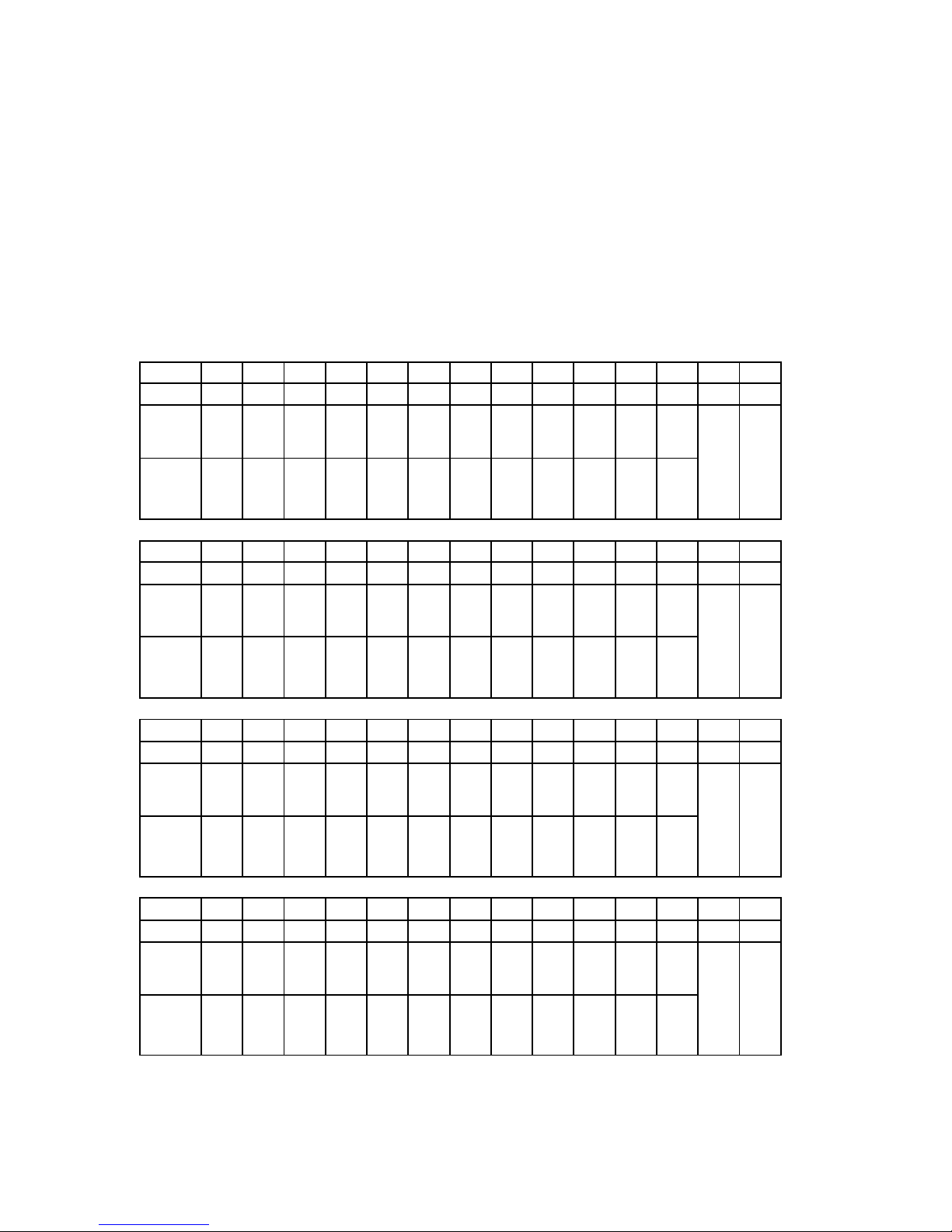
Figure 11. Model 4314R disk enclosure - example storage map
Model 4314R Disk Enclosure Shelf 4 (single-bus)
Bay 1234567891011121314
SCSI ID 00 01 02 03 04 05 08 09 10 11 12 13 14 15
D100
R1
D101
S1
M2
D103
M4
D105 D107
D108
S3
D1
S4
M6
D2R3D3S5D5S6D6
R4
spare
not
supported
not
supported
DISK ID
Disk40000
Disk40100
Disk40200
Disk40300
Disk40400
Disk40500
Disk40800
Disk40900
Disk41000
Disk41100
Disk41200
Disk41300
Model 4314R Disk Enclosure Shelf 1 (single-bus)
Bay 1234567891011121314
SCSI ID 00 01 02 03 04 05 08 09 10 11 12 13 14 15
D100
R1
D101
S1
M1
D102M3D104S2D106R2D108
S3
D1
S4
M5
D2R3D3S5D4M7D6R4D7
M8
not
supported
not
supported
DISK ID
Disk10000
Disk10100
Disk10200
Disk10300
Disk10400
Disk10500
Disk10800
Disk10900
Disk11000
Disk11100
Disk11200
Disk11300
Model 4314R Disk Enclosure Shelf 2 (single-bus)
Bay 1234567891011121314
SCSI ID 00 01 02 03 04 05 08 09 10 11 12 13 14 15
D100
R1
D101
S1
M1
D102M3D104S2D106R2D108
S3
D1
S4
M5
D2R3D3S5D4M7D6R4D7
M8
not
supported
not
supported
DISK ID
Disk20000
Disk20100
Disk20200
Disk20300
Disk20400
Disk20500
Disk20800
Disk20900
Disk21000
Disk21100
Disk21200
Disk21300
Model 4314R Disk Enclosure Shelf 3 (single-bus)
Bay 1234567891011121314
SCSI ID 00 01 02 03 04 05 08 09 10 11 12 13 14 15
D100
R1
D101
S1
M2
D103M4D104S2D106R2D108
S3
D1
S4
M6
D2R3D3S5D5S6D6
R4
spare
not
supported
not
supported
DISK ID
Disk30000
Disk30100
Disk30200
Disk30300
Disk30400
Disk30500
Disk30800
Disk30900
Disk31000
Disk31100
Disk31200
Disk31300
Page 18

18 Compaq StorageWorks Model 4300 Family Ultra3 LVD Disk Enclosure
Example Storage Map - Model 4354R Disk Enclosure
Figure 12 shows an example of three Model 4354R disk enclosur es (dual-bus).
■ Unit D100 is a 6-member RAID 3/5 storageset named R1. R1 consists of Disk10000,
Disk20000, Disk30000, Disk 40000, Disk50000, and Disk60000.
■ Unit D101is a 6-member RAID 3/5 stora ges et named R2. R2 consists of Dis k10100,
Disk20100, Disk30100, Disk 40100, Disk50100, and Disk60100.
■ Unit D102 is a 2-member str iped mirrorset named S1. S1 con si sts of M1 and M2:
❏ M1 is a 2-member mirrorset cons is ting of Disk10200 and Disk20200.
❏ M2 is a 2-member mirrorset cons is ting of Disk30200 and Disk40200.
■ Unit D103 is a 2-member mirrorset na me d M3. M3 con si sts of Disk50200 and
Disk60200.
■ Unit D104 is a 2-member str iped mirrorset named S2. S2 con si sts of M3 and M4:
❏ M3 is a 2-member mirrorset cons is ting of Disk10300 and Disk20300.
❏ M4 is a 2-member mirrorset cons is ting of Disk30300 and Disk40300.
■ Unit D105 is a 2-member str ipeset named S3. S3 consists of Disk50300 and
Disk60300.
■ Unit D1 is 4-member strip es et named S4. S4 consists of Dis k10400, Disk20400,
Disk30400, and Disk40400.
■ Unit D2 is a 2-member mirrorset named M5. M5 consists of Disk50400 and
Disk60400.
■ Unit D3 is a 2-member striped mirro rset named S5. S5 consists of M6 and M7:
❏ M6 is a 3-member mirrorset consisting of Disk10500, Disk20500, and Disk30500.
❏ M7 is a 2-member mirrorset cons is ting of Disk40500 and Disk50500.
■ Unit D4 is a single (JBOD) disk named Disk60500.
■ Unit D5 is a 4-member RAID 3/5 stor ageset named R3. R3 consists of Disk10800,
Disk20800, Disk30800, Disk and 40800.
■ Disk50800 and Disk60800 are spareset members.
Page 19
Addendum for Use with the MA8000/EMA12000 Storage System 19
Figure 12. Model 4354R disk enclosure - example storage map
Model 4354R Disk Enclosure Shelf 1 (dual-bus)
SCSI Bus A SCSI Bus B
Bay 1234567891011121314
SCSI ID 00 01 02 03 04 05 08 00 01 02 03 04 05 08
D100R1D101
R2
D102
S1
M1
D104
S2
M3
D1
S4
D3
S5
M6
D5R3D100R1D101
R2
D102
S1
M1
D104
S2
M3
D1
S4
D3
S5
M6
D5
R3
DISK ID
Disk10000
Disk10100
Disk10200
Disk10300
Disk10400
Disk10500
Disk10800
Disk20000
Disk20100
Disk20200
Disk20300
Disk20400
Disk20500
Disk20800
Model 4354R Disk Enclosure Shelf 2 (dual-bus)
SCSI Bus A SCSI Bus B
Bay 1234567891011121314
SCSI ID 00 01 02 03 04 05 08 00 01 02 03 04 05 08
D100R1D101
R2
D102
S1
M2
D104
S2
M4
D1
S4
D3
S5
M6
D5R3D100R1D101
R2
D102
S1
M2
D104
S2
M4
D1
S4
D3
S5
M7
D5
R3
DISK ID
Disk30000
Disk30100
Disk30200
Disk30300
Disk30400
Disk30500
Disk30800
Disk40000
Disk40100
Disk40200
Disk40300
Disk40400
Disk40500
Disk40800
Model 4354R Disk Enclosure Shelf 3 (dual-bus)
SCSI Bus A SCSI Bus B
Bay 1234567891011121314
SCSI ID 00 01 02 03 04 05 08 00 01 02 03 04 05 08
D100R1D101R2D103M3D105S3D2
M5
D3
S5M7spare
D100R1D112R2D103M3D105S3D2
M5
D4 spare
DISK ID
Disk50000
Disk50100
Disk50200
Disk50300
Disk50400
Disk50500
Disk50800
Disk60000
Disk60100
Disk60200
Disk60300
Disk60400
Disk60500
Disk60800
Page 20

20 Compaq StorageWorks Model 4300 Family Ultra3 LVD Disk Enclosure
Subsystem Enclosure Templates
The following are storage map te mp lates you can use to help keep track of the loc ation of
devices and storagesets in your shelves.
■ Storage Map Template for Model 4350R Disk Enclosure s
NOTE: The storage map templates for the Model 4310R and Model 4214R or 4314R reflect the
disk enclosures physical location in the rack. Disk enclosures 6, 5, and 4 are stacked above the
controller enclosure and disk enclosures 1, 2, and 3 are stacked below the controller enclosure.
■
Storage Map Template for Model 4310R Disk Enclosure s
■ Storage Map Template for Model 4214R or 4314R Disk Enclosures
■ Storage Map Template for Model 4254 or 4354R Disk Enclosures
Page 21
Addendum for Use with the MA8000/EMA12000 Storage System 21
Storage Map Template for Model 4350R Disk Enclosures
Model 4350R Disk Enclosure Shelf 1 (dual-bus)
SCSI Bus A SCSI Bus B
Bay 12345678910
SCSI ID 00 01 02 03 04 00 01 02 03 04
DISK ID
Disk10000
Disk10100
Disk10200
Disk10300
Disk10400
Disk20000
Disk20100
Disk20200
Disk20300
Disk20400
Model 4350R Disk Enclosure Shelf 2 (dual-bus)
SCSI Bus A SCSI Bus B
Bay 12345678910
SCSI ID 00 01 02 03 04 00 01 02 03 04
DISK ID
Disk30000
Disk30100
Disk30200
Disk30300
Disk30400
Disk40000
Disk40100
Disk40200
Disk40300
Disk40400
Model 4350R Disk Enclosure Shelf 3 (dual-bus)
SCSI Bus A SCSI Bus B
Bay 12345678910
SCSI ID 00 01 02 03 04 00 01 02 03 04
DISK ID
Disk50000
Disk50100
Disk50200
Disk50300
Disk50400
Disk60000
Disk60100
Disk60200
Disk60300
Disk60400
Page 22
22 Compaq StorageWorks Model 4300 Family Ultra3 LVD Disk Enclosure
Storage Map Template for Model 4310R Disk Enclosures
continued on the following page
Model 4310R Disk Enclosure Shelf 6 (single-bus)
Bay12345678910
SCSI ID 00 01 02 03 04 05 08 10 11 12
DISK ID
Disk60000
Disk60100
Disk60200
Disk60300
Disk60400
Disk60500
Disk60800
Disk61000
Disk61100
Disk61200
Model 4310R Disk Enclosure Shelf 5 (single-bus)
Bay12345678910
SCSI ID 00 01 02 03 04 05 08 10 11 12
DISK ID
Disk50000
Disk50100
Disk50200
Disk50300
Disk50400
Disk50500
Disk50800
Disk51000
Disk51100
Disk51200
Model 4310R Disk Enclosure Shelf 4 (single-bus)
Bay12345678910
SCSI ID 00 01 02 03 04 05 08 10 11 12
DISK ID
Disk40000
Disk40100
Disk40200
Disk40300
Disk40400
Disk40500
Disk40800
Disk41000
Disk41100
Disk41200
Page 23
Addendum for Use with the MA8000/EMA12000 Storage System 23
continued from previous page
Model 4310R Disk Enclosure Shelf 1 (single-bus)
Bay12345678910
SCSI ID 00 01 02 03 04 05 08 10 11 12
DISK ID
Disk10000
Disk10100
Disk10200
Disk10300
Disk10400
Disk10500
Disk10800
Disk11000
Disk11100
Disk11200
Model 4310R Disk Enclosure Shelf 2 (single-bus)
Bay12345678910
SCSI ID 00 01 02 03 04 05 08 10 11 12
DISK ID
Disk20000
Disk20100
Disk20200
Disk20300
Disk20400
Disk20500
Disk20800
Disk21000
Disk21100
Disk21200
Model 4310R Disk Enclosure Shelf 3 (single-bus)
Bay12345678910
SCSI ID 00 01 02 03 04 05 08 10 11 12
DISK ID
Disk30000
Disk30100
Disk30200
Disk30300
Disk30400
Disk30500
Disk30800
Disk31000
Disk31100
Disk31200
Page 24
24 Compaq StorageWorks Model 4300 Family Ultra3 LVD Disk Enclosure
Storage Map Template for Model 4214R or 4314R Disk
Enclosures
continued on the following page
Model 4314R Disk Enclosure Shelf 6 (single-bus)
Bay 1234567891011121314
SCSI ID 00 01 02 03 04 05 08 09 10 11 12 13 14 15
DISK ID
Disk60000
Disk60100
Disk60200
Disk60300
Disk60400
Disk60500
Disk60800
Disk60900
Disk61000
Disk61100
Disk61200
Disk61300
not
supported
not
supported
Model 4314R Disk Enclosure Shelf 5 (single-bus)
Bay 1234567891011121314
SCSI ID 00 01 02 03 04 05 08 09 10 11 12 13 14 15
DISK ID
Disk50000
Disk50100
Disk50200
Disk50300
Disk50400
Disk50500
Disk50800
Disk50900
Disk51000
Disk51100
Disk51200
Disk51300
not
supported
not
supported
Model 4314R Disk Enclosure Shelf 4 (single-bus)
Bay 1234567891011121314
SCSI ID 00 01 02 03 04 05 08 09 10 11 12 13 14 15
DISK ID
Disk10000
Disk10100
Disk10200
Disk10300
Disk10400
Disk10500
Disk10800
Disk10900
Disk11000
Disk11100
Disk11200
Disk11300
not
supported
not
supported
Page 25
Addendum for Use with the MA8000/EMA12000 Storage System 25
continued from the previous page
Model 4314R Disk Enclosure Shelf 1 (single-bus)
Bay 1234567891011121314
SCSI ID 00 01 02 03 04 05 08 09 10 11 12 13 14 15
DISK ID
Disk10000
Disk10100
Disk10200
Disk10300
Disk10400
Disk10500
Disk10800
Disk10900
Disk11000
Disk11100
Disk11200
Disk11300
not
supported
not
supported
Model 4314R Disk Enclosure Shelf 2 (single-bus)
Bay 1234567891011121314
SCSI ID 00 01 02 03 04 05 08 09 10 11 12 13 14 15
DISK ID
Disk20000
Disk20100
Disk20200
Disk20300
Disk20400
Disk20500
Disk20800
Disk20900
Disk21000
Disk21100
Disk21200
Disk21300
not
supported
not
supported
Model 4314R Disk Enclosure Shelf 3 (single-bus)
Bay 1234567891011121314
SCSI ID 00 01 02 03 04 05 08 09 10 11 12 13 14 15
DISK ID
Disk30000
Disk30100
Disk30200
Disk30300
Disk30400
Disk30500
Disk30800
Disk30900
Disk31000
Disk31100
Disk31200
Disk31300
not
supported
not
supported
Page 26

26 Compaq StorageWorks Model 4300 Family Ultra3 LVD Disk Enclosure
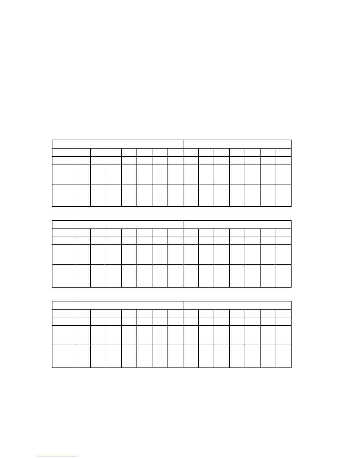
Storage Map Template for Model 4254 or 4354R Disk
Enclosures
Model 4354R Disk Enclosure Shelf 1 (dual-bus)
SCSI Bus A SCSI Bus B
Bay 1234567891011121314
SCSI ID 00 01 02 03 04 05 08 00 01 02 03 04 05 08
DISK ID
Disk10000
Disk10100
Disk10200
Disk10300
Disk10400
Disk10500
Disk10800
Disk20000
Disk20100
Disk20200
Disk20300
Disk20400
Disk20500
Disk20800
Model 4354R Disk Enclosure Shelf 2 (dual-bus)
SCSI Bus A SCSI Bus B
Bay 1234567891011121314
SCSI ID 00 01 02 03 04 05 08 00 01 02 03 04 05 08
DISK ID
Disk30000
Disk30100
Disk30200
Disk30300
Disk30400
Disk30500
Disk30800
Disk40000
Disk40100
Disk40200
Disk40300
Disk40400
Disk40500
Disk40800
Model 4354R Disk Enclosure Shelf 3 (dual-bus)
SCSI Bus A SCSI Bus B
Bay 1234567891011121314
SCSI ID 00 01 02 03 04 05 08 00 01 02 03 04 05 08
DISK ID
Disk50000
Disk50100
Disk50200
Disk50300
Disk50400
Disk50500
Disk50800
Disk60000
Disk60100
Disk60200
Disk60300
Disk60400
Disk60500
Disk60800
 Loading...