

Page 1

Alpha Architec ture Handbook
Order Number: EC–QD2KC–TE
Revision/Update Information:
This is Version 4 of the Alpha
Architecture Handbook.
Compaq Computer Corporation
Page 2

October 1998
The informatio n in this pu bl icat io n is subj ect to chang e with out noti ce.
COMP AQ COMPUTER CORPORATION SHALL NOT BE LIABLE FOR TECHNICAL OR EDITORIAL
ERRORS OR OMISSIONS CONTAINED HEREIN, NOR FOR INCIDENTAL OR CONSEQUENTIAL DAMAGES RESULTING FROM THE FURNISHING, PERFORMANCE, OR USE OF THIS MATERIAL. THIS
INFORMAT ION IS PROVIDED “AS IS” AND COMPAQ COMPUTER CORPORA TION DISCLAIMS ANY
WARRANTIES, EXPRESS, IMPLIED OR STATUTORY AND EXPRESSL Y DISCLAIMS THE IMPLIED WARRANTIES OF MERCHANTABILITY, FITNESS FOR PARTICULAR PURPOSE, GOOD TITLE AND AGAINST
INFRINGEMENT.
This publication contains inf or m ation protected by copyright. No part of thi s publicat ion may be photocopied or
reproduced in any form without prior written consent from Compaq Computer Corporation.
© Compaq Computer Corporation 1998.
All rights reserved. Printed in the U.S.A.
The following are trademarks of Comaq Computer Corporation: Alpha AXP, AXP, DEC, DIGITAL, DIGITAL
UNIX, OpenVMS, PDP–11, VAX, VAX DOCUMENT, and the DIGITAL logo.
Cray is a regis tered trademark of Cray Resear ch, Inc. IBM is a registered trademar k of International Business
Machines Co rporation. UNIX is a r egistered trademark in the United States and other countries licensed exclusively
through X/O pen Company Ltd. Windows NT is a trademark of Microsoft Corporation.
All other trademarks and registered t rademarks are the property of their res pective owners.
Page 3

Table of Contents
1 Introduction
1.1 The Alpha Approach to RISC Architecture . . . . . . . . . . . . . . . . . . . . . . . . . . . . . . . . . . . . . . 1–1
1.2 Data Format Overview . . . . . . . . . . . . . . . . . . . . . . . . . . . . . . . . . . . . . . . . . . . . . . . . . . . . . 1–3
1.3 Instruction Format Overview . . . . . . . . . . . . . . . . . . . . . . . . . . . . . . . . . . . . . . . . . . . . . . . . . 1–4
1.4 Instruction Overview . . . . . . . . . . . . . . . . . . . . . . . . . . . . . . . . . . . . . . . . . . . . . . . . . . . . . . . 1–4
1.5 Instruction Set Characteristics. . . . . . . . . . . . . . . . . . . . . . . . . . . . . . . . . . . . . . . . . . . . . . . . 1–6
1.6 Terminology and Conventions. . . . . . . . . . . . . . . . . . . . . . . . . . . . . . . . . . . . . . . . . . . . . . . . 1–6
1.6.1 Numbering . . . . . . . . . . . . . . . . . . . . . . . . . . . . . . . . . . . . . . . . . . . . . . . . . . . . . . . . . . . 1–7
1.6.2 Security Holes . . . . . . . . . . . . . . . . . . . . . . . . . . . . . . . . . . . . . . . . . . . . . . . . . . . . . . . . 1–7
1.6.3 UNPREDICTABLE and UNDEFINED . . . . . . . . . . . . . . . . . . . . . . . . . . . . . . . . . . . . . . 1–7
1.6.4 Ranges and Extent s. . . . . . . . . . . . . . . . . . . . . . . . . . . . . . . . . . . . . . . . . . . . . . . . . . . . 1–8
1.6.5 ALIGNED and UNALIGNED . . . . . . . . . . . . . . . . . . . . . . . . . . . . . . . . . . . . . . . . . . . . . 1–8
1.6.6 Must Be Zero (MBZ). . . . . . . . . . . . . . . . . . . . . . . . . . . . . . . . . . . . . . . . . . . . . . . . . . . . 1–9
1.6.7 Read As Zero (RAZ) . . . . . . . . . . . . . . . . . . . . . . . . . . . . . . . . . . . . . . . . . . . . . . . . . . . 1–9
1.6.8 Should Be Zero (SBZ) . . . . . . . . . . . . . . . . . . . . . . . . . . . . . . . . . . . . . . . . . . . . . . . . . . 1–9
1.6.9 Ignore (IGN). . . . . . . . . . . . . . . . . . . . . . . . . . . . . . . . . . . . . . . . . . . . . . . . . . . . . . . . . . 1–9
1.6.10 Implementati on Dependent (IMP) . . . . . . . . . . . . . . . . . . . . . . . . . . . . . . . . . . . . . . . . . 1–9
1.6.11 Illustration Conventions . . . . . . . . . . . . . . . . . . . . . . . . . . . . . . . . . . . . . . . . . . . . . . . . . 1–9
1.6.12 Macro Code Example Conve nti ons . . . . . . . . . . . . . . . . . . . . . . . . . . . . . . . . . . . . . . . . 1–9
2 Basic Architecture
2.1 Addressing . . . . . . . . . . . . . . . . . . . . . . . . . . . . . . . . . . . . . . . . . . . . . . . . . . . . . . . . . . . . . . 2 – 1
2.2 Data Types . . . . . . . . . . . . . . . . . . . . . . . . . . . . . . . . . . . . . . . . . . . . . . . . . . . . . . . . . . . . . . 2–1
2.2.1 Byte . . . . . . . . . . . . . . . . . . . . . . . . . . . . . . . . . . . . . . . . . . . . . . . . . . . . . . . . . . . . . . . . 2–1
2.2.2 Word. . . . . . . . . . . . . . . . . . . . . . . . . . . . . . . . . . . . . . . . . . . . . . . . . . . . . . . . . . . . . . . . 2–1
2.2.3 Longword . . . . . . . . . . . . . . . . . . . . . . . . . . . . . . . . . . . . . . . . . . . . . . . . . . . . . . . . . . . . 2–2
2.2.4 Quadword. . . . . . . . . . . . . . . . . . . . . . . . . . . . . . . . . . . . . . . . . . . . . . . . . . . . . . . . . . . . 2–2
2.2.5 VAX Floating-Point Formats. . . . . . . . . . . . . . . . . . . . . . . . . . . . . . . . . . . . . . . . . . . . . . 2–3
2.2.5.1 F_floating . . . . . . . . . . . . . . . . . . . . . . . . . . . . . . . . . . . . . . . . . . . . . . . . . . . . . . . . 2–3
2.2.5.2 G_floating . . . . . . . . . . . . . . . . . . . . . . . . . . . . . . . . . . . . . . . . . . . . . . . . . . . . . . . . 2–4
2.2.5.3 D_floating . . . . . . . . . . . . . . . . . . . . . . . . . . . . . . . . . . . . . . . . . . . . . . . . . . . . . . . . 2–5
2.2.6 IEEE Floating-Point Formats . . . . . . . . . . . . . . . . . . . . . . . . . . . . . . . . . . . . . . . . . . . . . 2–6
2.2.6.1 S_Floating. . . . . . . . . . . . . . . . . . . . . . . . . . . . . . . . . . . . . . . . . . . . . . . . . . . . . . . . 2–7
2.2.6.2 T_floating . . . . . . . . . . . . . . . . . . . . . . . . . . . . . . . . . . . . . . . . . . . . . . . . . . . . . . . . 2–8
2.2.6.3 X_Floating. . . . . . . . . . . . . . . . . . . . . . . . . . . . . . . . . . . . . . . . . . . . . . . . . . . . . . . . 2–9
2.2.7 Longword Integer Format in Floating-Point Unit . . . . . . . . . . . . . . . . . . . . . . . . . . . . . . 2–11
2.2.8 Quadword Integer Format in Floating-Point Unit . . . . . . . . . . . . . . . . . . . . . . . . . . . . . . 2–12
2.2.9 Data Types with No Hardware Support . . . . . . . . . . . . . . . . . . . . . . . . . . . . . . . . . . . . . 2–12
iii
Page 4

2.3 Bi g-Endian Addressing Support . . . . . . . . . . . . . . . . . . . . . . . . . . . . . . . . . . . . . . . . . . . . . . 2–13
3 Instruction Formats
3.1 Al pha Registers. . . . . . . . . . . . . . . . . . . . . . . . . . . . . . . . . . . . . . . . . . . . . . . . . . . . . . . . . . . 3–1
3.1.1 Program Counter . . . . . . . . . . . . . . . . . . . . . . . . . . . . . . . . . . . . . . . . . . . . . . . . . . . . . . 3–1
3.1.2 Integer Registers . . . . . . . . . . . . . . . . . . . . . . . . . . . . . . . . . . . . . . . . . . . . . . . . . . . . . . 3 – 1
3.1.3 Floating-Point Registers . . . . . . . . . . . . . . . . . . . . . . . . . . . . . . . . . . . . . . . . . . . . . . . . 3–2
3.1.4 Lock Registers . . . . . . . . . . . . . . . . . . . . . . . . . . . . . . . . . . . . . . . . . . . . . . . . . . . . . . . 3–2
3.1.5 Processor Cycle Counter (PCC) Register . . . . . . . . . . . . . . . . . . . . . . . . . . . . . . . . . . . 3–3
3.1.6 Optional Registers . . . . . . . . . . . . . . . . . . . . . . . . . . . . . . . . . . . . . . . . . . . . . . . . . . . . . 3–3
3.1.6.1 Memory Prefetch Registers . . . . . . . . . . . . . . . . . . . . . . . . . . . . . . . . . . . . . . . . . . 3–3
3.1.6.2 VAX Compatibility Regist er . . . . . . . . . . . . . . . . . . . . . . . . . . . . . . . . . . . . . . . . . . 3–3
3.2 Notation. . . . . . . . . . . . . . . . . . . . . . . . . . . . . . . . . . . . . . . . . . . . . . . . . . . . . . . . . . . . . . . . . 3–3
3.2.1 Operand Notation. . . . . . . . . . . . . . . . . . . . . . . . . . . . . . . . . . . . . . . . . . . . . . . . . . . . . . 3–4
3.2.2 Instructi on Operand Notation . . . . . . . . . . . . . . . . . . . . . . . . . . . . . . . . . . . . . . . . . . . . 3–5
3.2.2.1 Operand Name Notation . . . . . . . . . . . . . . . . . . . . . . . . . . . . . . . . . . . . . . . . . . . . . 3–5
3.2.2.2 Operand Access Type Notation . . . . . . . . . . . . . . . . . . . . . . . . . . . . . . . . . . . . . . . 3–5
3.2.2.3 Operand Data Type Notation . . . . . . . . . . . . . . . . . . . . . . . . . . . . . . . . . . . . . . . . . 3–6
3.2.3 Operators . . . . . . . . . . . . . . . . . . . . . . . . . . . . . . . . . . . . . . . . . . . . . . . . . . . . . . . . . . . 3–6
3.2.4 Notation Conventions . . . . . . . . . . . . . . . . . . . . . . . . . . . . . . . . . . . . . . . . . . . . . . . . . . 3–10
3.3 Instruction Formats . . . . . . . . . . . . . . . . . . . . . . . . . . . . . . . . . . . . . . . . . . . . . . . . . . . . . . . . 3–10
3.3.1 Memory Instruction Format . . . . . . . . . . . . . . . . . . . . . . . . . . . . . . . . . . . . . . . . . . . . . . 3–11
3.3.1.1 Memory Format Instructions with a Function Code . . . . . . . . . . . . . . . . . . . . . . . . 3–11
3.3.1.2 Memory Format Jump Instructions . . . . . . . . . . . . . . . . . . . . . . . . . . . . . . . . . . . . 3–12
3.3.2 Branch Instruction Format . . . . . . . . . . . . . . . . . . . . . . . . . . . . . . . . . . . . . . . . . . . . . . . 3–12
3.3.3 Operate Instruction Format . . . . . . . . . . . . . . . . . . . . . . . . . . . . . . . . . . . . . . . . . . . . . . 3–12
3.3.4 Floating-Point Operate Instruction Format . . . . . . . . . . . . . . . . . . . . . . . . . . . . . . . . . . 3–13
3.3.4.1 Floating-Point Convert Instructions. . . . . . . . . . . . . . . . . . . . . . . . . . . . . . . . . . . . . 3–14
3.3.4.2 Floating-Point/Integer Register Moves . . . . . . . . . . . . . . . . . . . . . . . . . . . . . . . . . . 3–14
3.3.5 PALcode Instruction Format . . . . . . . . . . . . . . . . . . . . . . . . . . . . . . . . . . . . . . . . . . . . . 3–14
4 Instruction Descriptions
4.1 Instruction Set Overview . . . . . . . . . . . . . . . . . . . . . . . . . . . . . . . . . . . . . . . . . . . . . . . . . . . 4– 1
4.1.1 Subsetting Rules . . . . . . . . . . . . . . . . . . . . . . . . . . . . . . . . . . . . . . . . . . . . . . . . . . . . . . 4–2
4.1.2 Floating-Point Subsets . . . . . . . . . . . . . . . . . . . . . . . . . . . . . . . . . . . . . . . . . . . . . . . . . 4–2
4.1.3 Software Emulation Rules . . . . . . . . . . . . . . . . . . . . . . . . . . . . . . . . . . . . . . . . . . . . . . . 4–3
4.1.4 Opcode Qualifiers . . . . . . . . . . . . . . . . . . . . . . . . . . . . . . . . . . . . . . . . . . . . . . . . . . . . . 4–3
4.2 Memory Integer Load/Store Instructions . . . . . . . . . . . . . . . . . . . . . . . . . . . . . . . . . . . . . . . 4–4
4.2.1 Load Address . . . . . . . . . . . . . . . . . . . . . . . . . . . . . . . . . . . . . . . . . . . . . . . . . . . . . . . . 4– 5
4.2.2 Load Memory Data into Int eger Register . . . . . . . . . . . . . . . . . . . . . . . . . . . . . . . . . . . 4–6
4.2.3 Load Unaligned Me mory Data into Integer Register . . . . . . . . . . . . . . . . . . . . . . . . . . . 4–8
4.2.4 Load Memory Data into Int eger Register Locked . . . . . . . . . . . . . . . . . . . . . . . . . . . . . 4–9
4.2.5 Store Integer Register Data into Memory Conditional . . . . . . . . . . . . . . . . . . . . . . . . . . 4–12
4.2.6 Store Integer Register Data into Memory . . . . . . . . . . . . . . . . . . . . . . . . . . . . . . . . . . . 4–15
4.2.7 Store Unaligned Integer Register Data into Memory . . . . . . . . . . . . . . . . . . . . . . . . . . . 4–17
4.3 Control Instructions . . . . . . . . . . . . . . . . . . . . . . . . . . . . . . . . . . . . . . . . . . . . . . . . . . . . . . . . 4 – 1 8
4.3.1 Conditional Branch. . . . . . . . . . . . . . . . . . . . . . . . . . . . . . . . . . . . . . . . . . . . . . . . . . . . . 4–20
4.3.2 Unconditional Branch . . . . . . . . . . . . . . . . . . . . . . . . . . . . . . . . . . . . . . . . . . . . . . . . . . 4–21
4.3.3 Jumps. . . . . . . . . . . . . . . . . . . . . . . . . . . . . . . . . . . . . . . . . . . . . . . . . . . . . . . . . . . . . . . 4–22
4.4 I nteger Arithmetic Instruct ions. . . . . . . . . . . . . . . . . . . . . . . . . . . . . . . . . . . . . . . . . . . . . . . . 4–24
4.4.1 Longword Add . . . . . . . . . . . . . . . . . . . . . . . . . . . . . . . . . . . . . . . . . . . . . . . . . . . . . . . . 4–25
4.4.2 Scaled Longword A dd . . . . . . . . . . . . . . . . . . . . . . . . . . . . . . . . . . . . . . . . . . . . . . . . . . 4–26
4.4.3 Quadword Add . . . . . . . . . . . . . . . . . . . . . . . . . . . . . . . . . . . . . . . . . . . . . . . . . . . . . . . . 4–27
4.4.4 Scaled Quadword Add . . . . . . . . . . . . . . . . . . . . . . . . . . . . . . . . . . . . . . . . . . . . . . . . . . 4–28
iv
Page 5

4.4.5 Integer Signed Compare . . . . . . . . . . . . . . . . . . . . . . . . . . . . . . . . . . . . . . . . . . . . . . . . 4–29
4.4.6 Integer Unsig ned Com pare . . . . . . . . . . . . . . . . . . . . . . . . . . . . . . . . . . . . . . . . . . . . . . 4–30
4.4.7 Count Leading Zero. . . . . . . . . . . . . . . . . . . . . . . . . . . . . . . . . . . . . . . . . . . . . . . . . . . . 4–31
4.4.8 Count Population . . . . . . . . . . . . . . . . . . . . . . . . . . . . . . . . . . . . . . . . . . . . . . . . . . . . . . 4–32
4.4.9 Count Trailing Zero . . . . . . . . . . . . . . . . . . . . . . . . . . . . . . . . . . . . . . . . . . . . . . . . . . . . 4–33
4.4.10 Longword Multiply . . . . . . . . . . . . . . . . . . . . . . . . . . . . . . . . . . . . . . . . . . . . . . . . . . . . . 4–34
4.4.11 Quadword Multiply . . . . . . . . . . . . . . . . . . . . . . . . . . . . . . . . . . . . . . . . . . . . . . . . . . . . . 4–35
4.4.12 Unsigned Quadword Mult iply High. . . . . . . . . . . . . . . . . . . . . . . . . . . . . . . . . . . . . . . . . 4–36
4.4.13 Longword Subtract . . . . . . . . . . . . . . . . . . . . . . . . . . . . . . . . . . . . . . . . . . . . . . . . . . . . . 4–37
4.4.14 Scaled Longword Subtr act. . . . . . . . . . . . . . . . . . . . . . . . . . . . . . . . . . . . . . . . . . . . . . . 4–38
4.4.15 Quadword Subtract . . . . . . . . . . . . . . . . . . . . . . . . . . . . . . . . . . . . . . . . . . . . . . . . . . . . 4–39
4.4.16 Scaled Quadword Subtract . . . . . . . . . . . . . . . . . . . . . . . . . . . . . . . . . . . . . . . . . . . . . . 4–40
4.5 Logical and Shift Instructions . . . . . . . . . . . . . . . . . . . . . . . . . . . . . . . . . . . . . . . . . . . . . . . . 4–41
4.5.1 Logical Functions . . . . . . . . . . . . . . . . . . . . . . . . . . . . . . . . . . . . . . . . . . . . . . . . . . . . . . 4–42
4.5.2 Conditional Move Integer . . . . . . . . . . . . . . . . . . . . . . . . . . . . . . . . . . . . . . . . . . . . . . . 4–43
4.5.3 Shift Logical . . . . . . . . . . . . . . . . . . . . . . . . . . . . . . . . . . . . . . . . . . . . . . . . . . . . . . . . . . 4 – 4 5
4.5.4 Shift Arithmetic. . . . . . . . . . . . . . . . . . . . . . . . . . . . . . . . . . . . . . . . . . . . . . . . . . . . . . . . 4–46
4.6 Byte Manipulation Instructions . . . . . . . . . . . . . . . . . . . . . . . . . . . . . . . . . . . . . . . . . . . . . . . 4–47
4.6.1 Compare Byte . . . . . . . . . . . . . . . . . . . . . . . . . . . . . . . . . . . . . . . . . . . . . . . . . . . . . . . . 4–49
4.6.2 Extract Byte . . . . . . . . . . . . . . . . . . . . . . . . . . . . . . . . . . . . . . . . . . . . . . . . . . . . . . . . . . 4–51
4.6.3 Byte Insert . . . . . . . . . . . . . . . . . . . . . . . . . . . . . . . . . . . . . . . . . . . . . . . . . . . . . . . . . . . 4– 5 5
4.6.4 Byte Mask . . . . . . . . . . . . . . . . . . . . . . . . . . . . . . . . . . . . . . . . . . . . . . . . . . . . . . . . . . . 4–57
4.6.5 Sign Extend . . . . . . . . . . . . . . . . . . . . . . . . . . . . . . . . . . . . . . . . . . . . . . . . . . . . . . . . . . 4–60
4.6.6 Zero Bytes . . . . . . . . . . . . . . . . . . . . . . . . . . . . . . . . . . . . . . . . . . . . . . . . . . . . . . . . . . . 4–61
4.7 Floating-Point Instructions. . . . . . . . . . . . . . . . . . . . . . . . . . . . . . . . . . . . . . . . . . . . . . . . . . . 4–62
4.7.1 Single-Precision Operations. . . . . . . . . . . . . . . . . . . . . . . . . . . . . . . . . . . . . . . . . . . . . . 4–62
4.7.2 Subsets and Faults . . . . . . . . . . . . . . . . . . . . . . . . . . . . . . . . . . . . . . . . . . . . . . . . . . . . 4–62
4.7.3 Definitions . . . . . . . . . . . . . . . . . . . . . . . . . . . . . . . . . . . . . . . . . . . . . . . . . . . . . . . . . . . 4–63
4.7.4 Encodings . . . . . . . . . . . . . . . . . . . . . . . . . . . . . . . . . . . . . . . . . . . . . . . . . . . . . . . . . . . 4–65
4.7.5 Rounding Modes . . . . . . . . . . . . . . . . . . . . . . . . . . . . . . . . . . . . . . . . . . . . . . . . . . . . . . 4–66
4.7.6 Computational Models . . . . . . . . . . . . . . . . . . . . . . . . . . . . . . . . . . . . . . . . . . . . . . . . . . 4–67
4.7.6.1 VAX-Format Arithmetic with Precise Exceptions . . . . . . . . . . . . . . . . . . . . . . . . . . 4–67
4.7.6.2 High-Performance VAX-Format Arithmetic. . . . . . . . . . . . . . . . . . . . . . . . . . . . . . . 4–68
4.7.6.3 IEEE-Compliant Ari thmetic . . . . . . . . . . . . . . . . . . . . . . . . . . . . . . . . . . . . . . . . . . . 4–68
4.7.6.4 IEEE-Compliant Ari thmetic Without Inexact Exception. . . . . . . . . . . . . . . . . . . . . . 4–68
4.7.6.5 High-Performance IEEE-Format Arithmetic . . . . . . . . . . . . . . . . . . . . . . . . . . . . . . 4–69
4.7.7 Trapping Modes. . . . . . . . . . . . . . . . . . . . . . . . . . . . . . . . . . . . . . . . . . . . . . . . . . . . . . . 4–69
4.7.7.1 VAX Trapping Modes . . . . . . . . . . . . . . . . . . . . . . . . . . . . . . . . . . . . . . . . . . . . . . . 4–69
4.7.7.2 IEEE Trapping Modes. . . . . . . . . . . . . . . . . . . . . . . . . . . . . . . . . . . . . . . . . . . . . . . 4–71
4.7.7.3 Arithmetic Trap Completion . . . . . . . . . . . . . . . . . . . . . . . . . . . . . . . . . . . . . . . . . . 4–73
4.7.7.3.1 Trap Shadow Rules. . . . . . . . . . . . . . . . . . . . . . . . . . . . . . . . . . . . . . . . . . . . . 4–73
4.7.7.3.2 Trap Shadow Length Rules. . . . . . . . . . . . . . . . . . . . . . . . . . . . . . . . . . . . . . . 4–74
4.7.7.4 Invalid Operation (INV) Arithmetic Trap . . . . . . . . . . . . . . . . . . . . . . . . . . . . . . . . . 4–76
4.7.7.5 Division by Zero (DZE) Arithmetic Trap . . . . . . . . . . . . . . . . . . . . . . . . . . . . . . . . . 4–77
4.7.7.6 Overflow (OVF) Arithmetic Trap . . . . . . . . . . . . . . . . . . . . . . . . . . . . . . . . . . . . . . . 4–77
4.7.7.7 Underflow (UNF) Arithmetic Trap . . . . . . . . . . . . . . . . . . . . . . . . . . . . . . . . . . . . . . 4–78
4.7.7.8 Inexact Result (INE) Arithmetic Trap . . . . . . . . . . . . . . . . . . . . . . . . . . . . . . . . . . . 4–78
4.7.7.9 Integer Overf low (IOV) Arithmetic Trap. . . . . . . . . . . . . . . . . . . . . . . . . . . . . . . . . . 4–78
4.7.7.10 IEEE Floating-Poi nt Trap Disable Bits . . . . . . . . . . . . . . . . . . . . . . . . . . . . . . . . . . 4–78
4.7.7.11 IEEE Denormal Control Bits . . . . . . . . . . . . . . . . . . . . . . . . . . . . . . . . . . . . . . . . . . 4–79
4.7.8 Floating-Point Control Register (FPCR). . . . . . . . . . . . . . . . . . . . . . . . . . . . . . . . . . . . . 4–79
4.7.8.1 Accessing the FPCR. . . . . . . . . . . . . . . . . . . . . . . . . . . . . . . . . . . . . . . . . . . . . . . . 4–82
4.7.8.2 Default Values of the FPCR . . . . . . . . . . . . . . . . . . . . . . . . . . . . . . . . . . . . . . . . . . 4–83
4.7.8.3 Saving and Restoring the FPCR. . . . . . . . . . . . . . . . . . . . . . . . . . . . . . . . . . . . . . . 4–83
4.7.9 Floating-Point Instruction Function Field Format . . . . . . . . . . . . . . . . . . . . . . . . . . . . . . 4–84
4.7.10 IEEE Standard . . . . . . . . . . . . . . . . . . . . . . . . . . . . . . . . . . . . . . . . . . . . . . . . . . . . . . . . 4–8 8
4.7.10.1 Conversion of NaN and Infinity Values . . . . . . . . . . . . . . . . . . . . . . . . . . . . . . . . . . 4–88
4.7.10.2 Copying NaN Values. . . . . . . . . . . . . . . . . . . . . . . . . . . . . . . . . . . . . . . . . . . . . . . . 4–89
4.7.10.3 Generating NaN Values . . . . . . . . . . . . . . . . . . . . . . . . . . . . . . . . . . . . . . . . . . . . . 4–89
v
Page 6

4.7.10.4 Propagating NaN Values . . . . . . . . . . . . . . . . . . . . . . . . . . . . . . . . . . . . . . . . . . . . 4–89
4.8 Memory Format Floating-Point Instructions . . . . . . . . . . . . . . . . . . . . . . . . . . . . . . . . . . . . . 4–90
4.8.1 Load F_floating . . . . . . . . . . . . . . . . . . . . . . . . . . . . . . . . . . . . . . . . . . . . . . . . . . . . . . . 4–91
4.8.2 Load G_floating . . . . . . . . . . . . . . . . . . . . . . . . . . . . . . . . . . . . . . . . . . . . . . . . . . . . . . . 4–92
4.8.3 Load S_floating . . . . . . . . . . . . . . . . . . . . . . . . . . . . . . . . . . . . . . . . . . . . . . . . . . . . . . . 4–93
4.8.4 Load T_floating . . . . . . . . . . . . . . . . . . . . . . . . . . . . . . . . . . . . . . . . . . . . . . . . . . . . . . 4–94
4.8.5 Store F_floating . . . . . . . . . . . . . . . . . . . . . . . . . . . . . . . . . . . . . . . . . . . . . . . . . . . . . . . 4–95
4.8.6 Store G_floating . . . . . . . . . . . . . . . . . . . . . . . . . . . . . . . . . . . . . . . . . . . . . . . . . . . . . . 4–96
4.8.7 Store S_floating . . . . . . . . . . . . . . . . . . . . . . . . . . . . . . . . . . . . . . . . . . . . . . . . . . . . . . . 4–97
4.8.8 Store T_floating . . . . . . . . . . . . . . . . . . . . . . . . . . . . . . . . . . . . . . . . . . . . . . . . . . . . . . . 4–98
4.9 Branch Format Floating-Point Instructions . . . . . . . . . . . . . . . . . . . . . . . . . . . . . . . . . . . . . . 4–99
4.9.1 Conditional Branch . . . . . . . . . . . . . . . . . . . . . . . . . . . . . . . . . . . . . . . . . . . . . . . . . . . . 4–100
4.10 Floating-Point Operate Format Instructions . . . . . . . . . . . . . . . . . . . . . . . . . . . . . . . . . . . . . 4–102
4.10.1 Copy Sign . . . . . . . . . . . . . . . . . . . . . . . . . . . . . . . . . . . . . . . . . . . . . . . . . . . . . . . . . . . 4–105
4.10.2 Convert Integer to Integer . . . . . . . . . . . . . . . . . . . . . . . . . . . . . . . . . . . . . . . . . . . . . . . 4–106
4.10.3 Floating- Point Conditional Move . . . . . . . . . . . . . . . . . . . . . . . . . . . . . . . . . . . . . . . . . . 4–107
4.10.4 Move from/to Floating-Point Control Register . . . . . . . . . . . . . . . . . . . . . . . . . . . . . . . . 4–109
4.10.5 VAX Floating Add . . . . . . . . . . . . . . . . . . . . . . . . . . . . . . . . . . . . . . . . . . . . . . . . . . . . . 4–110
4.10.6 IEEE Floating Add . . . . . . . . . . . . . . . . . . . . . . . . . . . . . . . . . . . . . . . . . . . . . . . . . . . . . 4–111
4.10.7 VAX Floating Compare . . . . . . . . . . . . . . . . . . . . . . . . . . . . . . . . . . . . . . . . . . . . . . . . . 4–112
4.10.8 IEEE Floating Compare . . . . . . . . . . . . . . . . . . . . . . . . . . . . . . . . . . . . . . . . . . . . . . . . 4–113
4.10.9 Convert VAX Floating to Integer . . . . . . . . . . . . . . . . . . . . . . . . . . . . . . . . . . . . . . . . . . 4–114
4.10.10 Convert Integer to VAX Floating . . . . . . . . . . . . . . . . . . . . . . . . . . . . . . . . . . . . . . . . . . 4–115
4.10.11 Convert VAX Floati ng to VAX Floating . . . . . . . . . . . . . . . . . . . . . . . . . . . . . . . . . . . . . 4–116
4.10.12 Convert IEEE Floating to Integer . . . . . . . . . . . . . . . . . . . . . . . . . . . . . . . . . . . . . . . . . 4–117
4.10.13 Convert Integer to IEEE Floating . . . . . . . . . . . . . . . . . . . . . . . . . . . . . . . . . . . . . . . . . 4–118
4.10.14 Convert IEEE S_Floating to IEEE T_Floating . . . . . . . . . . . . . . . . . . . . . . . . . . . . . . . . 4–119
4.10.15 Convert IEEE T_Floating to IEEE S_Floating . . . . . . . . . . . . . . . . . . . . . . . . . . . . . . . . 4–120
4.10.16 VAX Floating Divi de . . . . . . . . . . . . . . . . . . . . . . . . . . . . . . . . . . . . . . . . . . . . . . . . . . . 4–121
4.10.17 IEEE Floating Div ide . . . . . . . . . . . . . . . . . . . . . . . . . . . . . . . . . . . . . . . . . . . . . . . . . . . 4–122
4.10.18 Floati ng-Point Register to Integer Register Move . . . . . . . . . . . . . . . . . . . . . . . . . . . . . 4–123
4.10.19 Integer Register to Floating-Point Regis ter Move . . . . . . . . . . . . . . . . . . . . . . . . . . . . . 4–124
4.10.20 VAX Floating Mult ipl y . . . . . . . . . . . . . . . . . . . . . . . . . . . . . . . . . . . . . . . . . . . . . . . . . . 4–126
4.10.21 IEEE Floating Multiply . . . . . . . . . . . . . . . . . . . . . . . . . . . . . . . . . . . . . . . . . . . . . . . . . . 4–127
4.10.22 VAX Floating Square Root . . . . . . . . . . . . . . . . . . . . . . . . . . . . . . . . . . . . . . . . . . . . . . 4–128
4.10.23 IEEE Floating Square Root . . . . . . . . . . . . . . . . . . . . . . . . . . . . . . . . . . . . . . . . . . . . . . 4–129
4.10.24 VAX Floating Subtract . . . . . . . . . . . . . . . . . . . . . . . . . . . . . . . . . . . . . . . . . . . . . . . . . . 4–130
4.10.25 IEEE Floati ng Subtract . . . . . . . . . . . . . . . . . . . . . . . . . . . . . . . . . . . . . . . . . . . . . . . . . 4–131
4.11 Miscellaneous Instructions . . . . . . . . . . . . . . . . . . . . . . . . . . . . . . . . . . . . . . . . . . . . . . . . . . 4–132
4.11.1 Architecture Mask . . . . . . . . . . . . . . . . . . . . . . . . . . . . . . . . . . . . . . . . . . . . . . . . . . . . . 4–133
4.11.2 Call Privileged Architecture Library . . . . . . . . . . . . . . . . . . . . . . . . . . . . . . . . . . . . . . . . 4–135
4.11.3 Evict Data Cache Block . . . . . . . . . . . . . . . . . . . . . . . . . . . . . . . . . . . . . . . . . . . . . . . . . 4–136
4.11.4 Exception Barrier . . . . . . . . . . . . . . . . . . . . . . . . . . . . . . . . . . . . . . . . . . . . . . . . . . . . . 4–138
4.11.5 Prefetch Data . . . . . . . . . . . . . . . . . . . . . . . . . . . . . . . . . . . . . . . . . . . . . . . . . . . . . . . . 4–139
4.11.6 Implementation Version . . . . . . . . . . . . . . . . . . . . . . . . . . . . . . . . . . . . . . . . . . . . . . . . 4–141
4.11.7 Memory Barrier . . . . . . . . . . . . . . . . . . . . . . . . . . . . . . . . . . . . . . . . . . . . . . . . . . . . . . . 4–142
4.11.8 Read Processor Cycle Counter . . . . . . . . . . . . . . . . . . . . . . . . . . . . . . . . . . . . . . . . . . . 4–143
4.11.9 Trap Barrier . . . . . . . . . . . . . . . . . . . . . . . . . . . . . . . . . . . . . . . . . . . . . . . . . . . . . . . . . . 4–144
4.11.10 Write Hint . . . . . . . . . . . . . . . . . . . . . . . . . . . . . . . . . . . . . . . . . . . . . . . . . . . . . . . . . . . 4–145
4.11.11 Write Memory Barrier . . . . . . . . . . . . . . . . . . . . . . . . . . . . . . . . . . . . . . . . . . . . . . . . . . 4–147
4.12 VAX Compatibility Instructions . . . . . . . . . . . . . . . . . . . . . . . . . . . . . . . . . . . . . . . . . . . . . . . 4–149
4.12.1 VAX Compatibility Instructions . . . . . . . . . . . . . . . . . . . . . . . . . . . . . . . . . . . . . . . . . . . 4–150
4.13 Multimedia (Graphics and Video) Support . . . . . . . . . . . . . . . . . . . . . . . . . . . . . . . . . . . . . . 4–151
4.13.1 Byte and Word Minimum and Maxi m um . . . . . . . . . . . . . . . . . . . . . . . . . . . . . . . . . . . . 4–152
4.13.2 Pixel Error . . . . . . . . . . . . . . . . . . . . . . . . . . . . . . . . . . . . . . . . . . . . . . . . . . . . . . . . . . 4–154
4.13.3 Pack Bytes . . . . . . . . . . . . . . . . . . . . . . . . . . . . . . . . . . . . . . . . . . . . . . . . . . . . . . . . . . 4–155
4.13.4 Unpack Bytes . . . . . . . . . . . . . . . . . . . . . . . . . . . . . . . . . . . . . . . . . . . . . . . . . . . . . . . . 4–156
vi
Page 7

5 System Architecture and Programming Implications
5.1 Introduction . . . . . . . . . . . . . . . . . . . . . . . . . . . . . . . . . . . . . . . . . . . . . . . . . . . . . . . . . . . . . . 5–1
5.2 Physical Address Space Characteristics. . . . . . . . . . . . . . . . . . . . . . . . . . . . . . . . . . . . . . . . 5–1
5.2.1 Coherency of Memory Access . . . . . . . . . . . . . . . . . . . . . . . . . . . . . . . . . . . . . . . . . . . . 5–1
5.2.2 Granularit y of Mem ory Access. . . . . . . . . . . . . . . . . . . . . . . . . . . . . . . . . . . . . . . . . . . . 5–2
5.2.3 Width of Memory Access . . . . . . . . . . . . . . . . . . . . . . . . . . . . . . . . . . . . . . . . . . . . . . . . 5–3
5.2.4 Memory-Lik e and Non-Mem ory-Like Behavior. . . . . . . . . . . . . . . . . . . . . . . . . . . . . . . . 5–3
5.3 Tr anslation Buffers and Virtual Caches. . . . . . . . . . . . . . . . . . . . . . . . . . . . . . . . . . . . . . . . . 5–4
5.4 Caches and Write Buffers . . . . . . . . . . . . . . . . . . . . . . . . . . . . . . . . . . . . . . . . . . . . . . . . . . . 5–4
5.5 Data Sharing . . . . . . . . . . . . . . . . . . . . . . . . . . . . . . . . . . . . . . . . . . . . . . . . . . . . . . . . . . . . . 5–6
5.5.1 Atomic Change of a Single Datum. . . . . . . . . . . . . . . . . . . . . . . . . . . . . . . . . . . . . . . . . 5–6
5.5.2 Atomic Update of a Single Datum . . . . . . . . . . . . . . . . . . . . . . . . . . . . . . . . . . . . . . . . . 5–6
5.5.3 Atomic Update of Data Structures . . . . . . . . . . . . . . . . . . . . . . . . . . . . . . . . . . . . . . . . . 5–7
5.5.4 Ordering Considerations for Shared Data Structures . . . . . . . . . . . . . . . . . . . . . . . . . . 5–9
5.6 Read/Write Ordering . . . . . . . . . . . . . . . . . . . . . . . . . . . . . . . . . . . . . . . . . . . . . . . . . . . . . . . 5–10
5.6.1 Alpha Shared Memory Mode l. . . . . . . . . . . . . . . . . . . . . . . . . . . . . . . . . . . . . . . . . . . . . 5–10
5.6.1.1 Architectural Definition of Processor Iss ue Sequence . . . . . . . . . . . . . . . . . . . . . . 5–12
5.6.1.2 Definition of Before and After . . . . . . . . . . . . . . . . . . . . . . . . . . . . . . . . . . . . . . . . . 5–12
5.6.1.3 Definition of Processor Issue Constraints . . . . . . . . . . . . . . . . . . . . . . . . . . . . . . . . 5–12
5.6.1.4 Definition of Location Access Constraints. . . . . . . . . . . . . . . . . . . . . . . . . . . . . . . . 5–14
5.6.1.5 Definition of Visibility . . . . . . . . . . . . . . . . . . . . . . . . . . . . . . . . . . . . . . . . . . . . . . . 5–14
5.6.1.6 Definition of Storage . . . . . . . . . . . . . . . . . . . . . . . . . . . . . . . . . . . . . . . . . . . . . . . . 5–14
5.6.1.7 Definition of Dependence Constraint . . . . . . . . . . . . . . . . . . . . . . . . . . . . . . . . . . . 5–15
5.6.1.8 Definition of Load-Locked and Store-Conditional. . . . . . . . . . . . . . . . . . . . . . . . . . 5–16
5.6.1.9 Timeliness. . . . . . . . . . . . . . . . . . . . . . . . . . . . . . . . . . . . . . . . . . . . . . . . . . . . . . . . 5–17
5.6.2 Litmus Tests. . . . . . . . . . . . . . . . . . . . . . . . . . . . . . . . . . . . . . . . . . . . . . . . . . . . . . . . . . 5–17
5.6.2.1 Litmus Test 1 (Impossible Sequence). . . . . . . . . . . . . . . . . . . . . . . . . . . . . . . . . . . 5–17
5.6.2.2 Litmus Test 2 (Impossible Sequence). . . . . . . . . . . . . . . . . . . . . . . . . . . . . . . . . . . 5–18
5.6.2.3 Litmus Test 3 (Impossible Sequence). . . . . . . . . . . . . . . . . . . . . . . . . . . . . . . . . . . 5–18
5.6.2.4 Litmus Test 4 (Sequence Okay) . . . . . . . . . . . . . . . . . . . . . . . . . . . . . . . . . . . . . . . 5–19
5.6.2.5 Litmus Test 5 (Sequence Okay) . . . . . . . . . . . . . . . . . . . . . . . . . . . . . . . . . . . . . . . 5–19
5.6.2.6 Litmus Test 6 (Sequence Okay) . . . . . . . . . . . . . . . . . . . . . . . . . . . . . . . . . . . . . . . 5–19
5.6.2.7 Litmus Test 7 (Impossible Sequence). . . . . . . . . . . . . . . . . . . . . . . . . . . . . . . . . . . 5–20
5.6.2.8 Litmus Test 8 (Impossible Sequence). . . . . . . . . . . . . . . . . . . . . . . . . . . . . . . . . . . 5–20
5.6.2.9 Litmus Test 9 (Impossible Sequence). . . . . . . . . . . . . . . . . . . . . . . . . . . . . . . . . . . 5–21
5.6.2.10 Litmus Test 10 (Sequence Okay) . . . . . . . . . . . . . . . . . . . . . . . . . . . . . . . . . . . . . . 5–21
5.6.2.11 Litmus Test 11 (Impossible Sequence). . . . . . . . . . . . . . . . . . . . . . . . . . . . . . . . . . 5–21
5.6.3 Implied Barriers . . . . . . . . . . . . . . . . . . . . . . . . . . . . . . . . . . . . . . . . . . . . . . . . . . . . . . . 5–22
5.6.4 Implications for Software . . . . . . . . . . . . . . . . . . . . . . . . . . . . . . . . . . . . . . . . . . . . . . . . 5–22
5.6.4.1 Single Processor Data Stream . . . . . . . . . . . . . . . . . . . . . . . . . . . . . . . . . . . . . . . . 5–22
5.6.4.2 Single Processor Instruction Stream. . . . . . . . . . . . . . . . . . . . . . . . . . . . . . . . . . . . 5–22
5.6.4.3 Multiprocessor Data Stream (Including Single Processor with DMA I/O) . . . . . . . . 5–22
5.6.4.4 Multiproce ssor Instruction Stream (Includin g Singl e Processor with DMA I/O) . . . 5–23
5.6.4.5 Multiprocessor Context Switch . . . . . . . . . . . . . . . . . . . . . . . . . . . . . . . . . . . . . . . . 5–24
5.6.4.6 Multiprocessor Send/Receive Interrupt. . . . . . . . . . . . . . . . . . . . . . . . . . . . . . . . . . 5–26
5.6.4.7 Implicati ons for Memory Mapped I/O . . . . . . . . . . . . . . . . . . . . . . . . . . . . . . . . . . . 5–27
5.6.4.8 Multiple Processors Writing to a Single I/O Device. . . . . . . . . . . . . . . . . . . . . . . . . 5–28
5.6.5 Implications for Hardware . . . . . . . . . . . . . . . . . . . . . . . . . . . . . . . . . . . . . . . . . . . . . . . 5–29
5.7 Arithmetic Traps . . . . . . . . . . . . . . . . . . . . . . . . . . . . . . . . . . . . . . . . . . . . . . . . . . . . . . . . . . 5–30
6 Common PALcode Architecture
6.1 PALcode . . . . . . . . . . . . . . . . . . . . . . . . . . . . . . . . . . . . . . . . . . . . . . . . . . . . . . . . . . . . . . . . 6–1
6.2 PALcode Instructions and Functions. . . . . . . . . . . . . . . . . . . . . . . . . . . . . . . . . . . . . . . . . . . 6–1
6.3 PALcode Environment. . . . . . . . . . . . . . . . . . . . . . . . . . . . . . . . . . . . . . . . . . . . . . . . . . . . . . 6–2
6.4 Special Functions Required for PALcode . . . . . . . . . . . . . . . . . . . . . . . . . . . . . . . . . . . . . . . 6–2
vii
Page 8

6.5 PALcode Effects on System Code . . . . . . . . . . . . . . . . . . . . . . . . . . . . . . . . . . . . . . . . . . . . 6–3
6.6 PALcode Replacement . . . . . . . . . . . . . . . . . . . . . . . . . . . . . . . . . . . . . . . . . . . . . . . . . . . . . 6–3
6.7 Required PALcode Instructions. . . . . . . . . . . . . . . . . . . . . . . . . . . . . . . . . . . . . . . . . . . . . . . 6–4
6.7.1 Drain Aborts . . . . . . . . . . . . . . . . . . . . . . . . . . . . . . . . . . . . . . . . . . . . . . . . . . . . . . . . . . 6–6
6.7.2 Halt. . . . . . . . . . . . . . . . . . . . . . . . . . . . . . . . . . . . . . . . . . . . . . . . . . . . . . . . . . . . . . . . . 6–7
6.7.3 Instruction Memory Barrier. . . . . . . . . . . . . . . . . . . . . . . . . . . . . . . . . . . . . . . . . . . . . . . 6–8
7 Console Subsystem Overview
8 Input/Output Overview
9 OpenVMS Alpha
9.1 Unprivileged OpenVMS Alpha PALcode. . . . . . . . . . . . . . . . . . . . . . . . . . . . . . . . . . . . . . . . 9–1
9.2 Pr ivileged OpenVMS Alpha Palcode . . . . . . . . . . . . . . . . . . . . . . . . . . . . . . . . . . . . . . . . . . 9–8
10 Digital UNIX
10.1 Unprivileged Digital UNIX PALcode . . . . . . . . . . . . . . . . . . . . . . . . . . . . . . . . . . . . . . . . . . . 10–1
10.2 Privileged Digital UNIX PALcode . . . . . . . . . . . . . . . . . . . . . . . . . . . . . . . . . . . . . . . . . . . . . 10–2
11 Windows NT Alpha
11.1 Unprivileged Windows NT Alpha PALcode. . . . . . . . . . . . . . . . . . . . . . . . . . . . . . . . . . . . . . 11–1
11.2 Privileged Windows NT Alpha PALcode . . . . . . . . . . . . . . . . . . . . . . . . . . . . . . . . . . . . . . . . 11–2
A Software Considerations
A.1 Hardware-Software Compact . . . . . . . . . . . . . . . . . . . . . . . . . . . . . . . . . . . . . . . . . . . . . . . . A–1
A.2 Instruction-Stream Considerations . . . . . . . . . . . . . . . . . . . . . . . . . . . . . . . . . . . . . . . . . . . . A–2
A.2.1 Instruction Alignment . . . . . . . . . . . . . . . . . . . . . . . . . . . . . . . . . . . . . . . . . . . . . . . . . . . A–2
A.2.2 Branch Predict ion and Minimizing Branch-Taken — Factor of 3 . . . . . . . . . . . . . . . . . . A–2
A.2.3 Improving I-Stream Density — Factor of 3. . . . . . . . . . . . . . . . . . . . . . . . . . . . . . . . . . . A–4
A.2.4 Instruction Scheduling — Factor of 3. . . . . . . . . . . . . . . . . . . . . . . . . . . . . . . . . . . . . . . A–4
A.3 Data-Stream Considerations . . . . . . . . . . . . . . . . . . . . . . . . . . . . . . . . . . . . . . . . . . . . . . . . A–4
A.3.1 Data Alignment — Factor of 10. . . . . . . . . . . . . . . . . . . . . . . . . . . . . . . . . . . . . . . . . . . A–4
A.3.2 Shared Data in Multiple Processors — Factor of 3 . . . . . . . . . . . . . . . . . . . . . . . . . . . . A–5
A.3.3 Avoiding Cache/TB Conflicts — Factor of 1 . . . . . . . . . . . . . . . . . . . . . . . . . . . . . . . . . A–6
A.3.4 Sequential Read/Writ e — Factor of 1 . . . . . . . . . . . . . . . . . . . . . . . . . . . . . . . . . . . . . . A–8
A.3.5 Prefetching — Factor of 3 . . . . . . . . . . . . . . . . . . . . . . . . . . . . . . . . . . . . . . . . . . . . . . . A–8
A.4 Code Sequences . . . . . . . . . . . . . . . . . . . . . . . . . . . . . . . . . . . . . . . . . . . . . . . . . . . . . . . . . A–9
A.4.1 Aligned Byte/ Word (W ithin Register) Memory Accesses. . . . . . . . . . . . . . . . . . . . . . . . A–9
A.4.2 Division . . . . . . . . . . . . . . . . . . . . . . . . . . . . . . . . . . . . . . . . . . . . . . . . . . . . . . . . . . . . . A–10
A.4.3 Byte Swap. . . . . . . . . . . . . . . . . . . . . . . . . . . . . . . . . . . . . . . . . . . . . . . . . . . . . . . . . . . A–11
A.4.4 Stylized Code Forms. . . . . . . . . . . . . . . . . . . . . . . . . . . . . . . . . . . . . . . . . . . . . . . . . . . A–11
A.4.4.1 NOP. . . . . . . . . . . . . . . . . . . . . . . . . . . . . . . . . . . . . . . . . . . . . . . . . . . . . . . . . . . . A–11
A.4.4.2 Clear a Register . . . . . . . . . . . . . . . . . . . . . . . . . . . . . . . . . . . . . . . . . . . . . . . . . . . A–12
A.4.4.3 Load Literal . . . . . . . . . . . . . . . . . . . . . . . . . . . . . . . . . . . . . . . . . . . . . . . . . . . . . . A–12
A.4.4.4 Register-to-Register Move . . . . . . . . . . . . . . . . . . . . . . . . . . . . . . . . . . . . . . . . . . . A–13
A.4.4.5 Negate . . . . . . . . . . . . . . . . . . . . . . . . . . . . . . . . . . . . . . . . . . . . . . . . . . . . . . . . . . A–13
viii
Page 9

A.4.4.6 NOT . . . . . . . . . . . . . . . . . . . . . . . . . . . . . . . . . . . . . . . . . . . . . . . . . . . . . . . . . . . . A–13
A.4.4.7 Booleans . . . . . . . . . . . . . . . . . . . . . . . . . . . . . . . . . . . . . . . . . . . . . . . . . . . . . . . . A–13
A.4.5 Exceptions and Trap Barriers. . . . . . . . . . . . . . . . . . . . . . . . . . . . . . . . . . . . . . . . . . . . . A–14
A.4.6 Pseudo-Oper ati ons (Stylized Code Forms) . . . . . . . . . . . . . . . . . . . . . . . . . . . . . . . . . . A–14
A.5 Timing Considerations: Atomi c Sequences . . . . . . . . . . . . . . . . . . . . . . . . . . . . . . . . . . . . . A–16
B IEEE Floating-Point Conformance
B.1 Alpha Choices for IEEE Options . . . . . . . . . . . . . . . . . . . . . . . . . . . . . . . . . . . . . . . . . . . . . . B–1
B.2 Alpha Support for OS Completion Handlers . . . . . . . . . . . . . . . . . . . . . . . . . . . . . . . . . . . . . B–3
B.2.1 IEEE Floating-Poi nt Cont rol (FP_C) Quadword . . . . . . . . . . . . . . . . . . . . . . . . . . . . . . B–4
B.3 Mapping to IEEE Standard . . . . . . . . . . . . . . . . . . . . . . . . . . . . . . . . . . . . . . . . . . . . . . . . . . B–6
C Instruction Summary
C.1 Common Architecture Instruction Summary . . . . . . . . . . . . . . . . . . . . . . . . . . . . . . . . . . . . . C–1
C.2 IEEE Floating- Point Instructions . . . . . . . . . . . . . . . . . . . . . . . . . . . . . . . . . . . . . . . . . . . . . . C–6
C.3 VAX Floating-Point Instructions. . . . . . . . . . . . . . . . . . . . . . . . . . . . . . . . . . . . . . . . . . . . . . . C–7
C.4 Independent Floating-Point Instructions . . . . . . . . . . . . . . . . . . . . . . . . . . . . . . . . . . . . . . . . C–8
C.5 Opcode Summary . . . . . . . . . . . . . . . . . . . . . . . . . . . . . . . . . . . . . . . . . . . . . . . . . . . . . . . . . C–8
C.6 Common Architecture Opcodes in Numerical Order. . . . . . . . . . . . . . . . . . . . . . . . . . . . . . . C–10
C.7 OpenVMS Alpha PALcode Instruction Summary . . . . . . . . . . . . . . . . . . . . . . . . . . . . . . . . . C–14
C.8 DIGITAL UNIX PALcode Instruction Summary. . . . . . . . . . . . . . . . . . . . . . . . . . . . . . . . . . . C–16
C.9 Windows NT Alpha Instruction Summary . . . . . . . . . . . . . . . . . . . . . . . . . . . . . . . . . . . . . . . C–17
C.10 PALcode Opcodes in Numerical Order . . . . . . . . . . . . . . . . . . . . . . . . . . . . . . . . . . . . . . . . . C–18
C.11 Required PALcode Opcodes. . . . . . . . . . . . . . . . . . . . . . . . . . . . . . . . . . . . . . . . . . . . . . . . . C–20
C.12 Opcodes Reserved to PALcode . . . . . . . . . . . . . . . . . . . . . . . . . . . . . . . . . . . . . . . . . . . . . . C–20
C.13 Opcodes Reserved to Compaq. . . . . . . . . . . . . . . . . . . . . . . . . . . . . . . . . . . . . . . . . . . . . . . C–21
C.14 Unused Function Code Behavior . . . . . . . . . . . . . . . . . . . . . . . . . . . . . . . . . . . . . . . . . . . . . C–21
C.15 ASCII Character Set . . . . . . . . . . . . . . . . . . . . . . . . . . . . . . . . . . . . . . . . . . . . . . . . . . . . . . . C–22
D Registered System and Processor Identifiers
D.1 Processor Type Assignments . . . . . . . . . . . . . . . . . . . . . . . . . . . . . . . . . . . . . . . . . . . . . . . . D–1
D.2 PALcode Variation Assignments . . . . . . . . . . . . . . . . . . . . . . . . . . . . . . . . . . . . . . . . . . . . . D–2
D.3 Architecture Mask and Implementation Values . . . . . . . . . . . . . . . . . . . . . . . . . . . . . . . . . . . D–3
E Waivers and Implementation-Dependent Functionality
E.1 Waivers . . . . . . . . . . . . . . . . . . . . . . . . . . . . . . . . . . . . . . . . . . . . . . . . . . . . . . . . . . . . . . . . E–1
E.1.1 DECchip 21064, DECchip 21066, and DECchip 21068 IEEE Divide Instruction Violation E–1
E.1.2 DECchip 21064, DECchip 21066, and DECchip 21068 Write Buffer Violation . . . . . . . E–2
E.1.3 DECchip 21264 LDx_L/STx_C with WH64 Violation . . . . . . . . . . . . . . . . . . . . . . . . . . . E–2
E.2 Implementation-Specific Functionality. . . . . . . . . . . . . . . . . . . . . . . . . . . . . . . . . . . . . . . . . . E–3
E.2.1 DECchip 21064/21066/21068 Performance Monitori ng . . . . . . . . . . . . . . . . . . . . . . . . E–3
E.2.1.1 DECchip 21064/21066/21068 Performance Monitor Interrupt Mechanism . . . . . . E–4
E.2.1.2 Functions and Arguments for the DECchip 21064/21066/2 1068 . . . . . . . . . . . . . . E–5
E.2.2 DECchip 21164/21164PC Per formance Monitoring . . . . . . . . . . . . . . . . . . . . . . . . . . . E–9
E.2.2.1 Performance Mon it or Interrupt Mechanism. . . . . . . . . . . . . . . . . . . . . . . . . . . . . . . E–9
ix
Page 10

E.2.2.2 Windows NT Alpha Functions and Argument . . . . . . . . . . . . . . . . . . . . . . . . . . . . . E–10
E.2.2.3 OpenVMS Alpha and DIGITAL UNIX Functions and Arguments . . . . . . . . . . . . . . E–12
E.2.3 21264 Performance M onitoring . . . . . . . . . . . . . . . . . . . . . . . . . . . . . . . . . . . . . . . . . . . E–23
E.2.3.1 Performance Mon it or Interrupt Mechanism. . . . . . . . . . . . . . . . . . . . . . . . . . . . . . . E–23
E.2.3.2 Windows NT Alpha Functions and Argument . . . . . . . . . . . . . . . . . . . . . . . . . . . . . E–24
E.2.3.3 OpenVMS Alpha and DIGITAL UNIX Functions and Arguments . . . . . . . . . . . . . . E–25
Index
x
Page 11

Figures
1–1 Instruction Format Overview . . . . . . . . . . . . . . . . . . . . . . . . . . . . . . . . . . . . . . . . . . . . . . . . . 1–4
2–1 Byte Format. . . . . . . . . . . . . . . . . . . . . . . . . . . . . . . . . . . . . . . . . . . . . . . . . . . . . . . . . . . . . . 2–1
2–2 Word Format . . . . . . . . . . . . . . . . . . . . . . . . . . . . . . . . . . . . . . . . . . . . . . . . . . . . . . . . . . . . . 2–2
2–3 Longword Format . . . . . . . . . . . . . . . . . . . . . . . . . . . . . . . . . . . . . . . . . . . . . . . . . . . . . . . . . 2–2
2–4 Quadword Format . . . . . . . . . . . . . . . . . . . . . . . . . . . . . . . . . . . . . . . . . . . . . . . . . . . . . . . . . 2–2
2–5 F_floating Datum . . . . . . . . . . . . . . . . . . . . . . . . . . . . . . . . . . . . . . . . . . . . . . . . . . . . . . . . . . 2–3
2–6 F_floating Register Format . . . . . . . . . . . . . . . . . . . . . . . . . . . . . . . . . . . . . . . . . . . . . . . . . . 2–3
2–7 G_floating Datum . . . . . . . . . . . . . . . . . . . . . . . . . . . . . . . . . . . . . . . . . . . . . . . . . . . . . . . . . 2–4
2–8 G_floating Register Format . . . . . . . . . . . . . . . . . . . . . . . . . . . . . . . . . . . . . . . . . . . . . . . . . . 2–5
2–9 D_floating Datum. . . . . . . . . . . . . . . . . . . . . . . . . . . . . . . . . . . . . . . . . . . . . . . . . . . . . . . . . . 2–5
2–10 D_floating Register Format . . . . . . . . . . . . . . . . . . . . . . . . . . . . . . . . . . . . . . . . . . . . . . . . . . 2–5
2–11 S_floating Datum. . . . . . . . . . . . . . . . . . . . . . . . . . . . . . . . . . . . . . . . . . . . . . . . . . . . . . . . . . 2–7
2–12 S_floating Register Format . . . . . . . . . . . . . . . . . . . . . . . . . . . . . . . . . . . . . . . . . . . . . . . . . . 2–7
2–13 T_floating Datum. . . . . . . . . . . . . . . . . . . . . . . . . . . . . . . . . . . . . . . . . . . . . . . . . . . . . . . . . . 2–8
2–14 T_floating Register Format . . . . . . . . . . . . . . . . . . . . . . . . . . . . . . . . . . . . . . . . . . . . . . . . . . 2–9
2–15 X_floating Datum. . . . . . . . . . . . . . . . . . . . . . . . . . . . . . . . . . . . . . . . . . . . . . . . . . . . . . . . . . 2–10
2–16 X_floating Register Format . . . . . . . . . . . . . . . . . . . . . . . . . . . . . . . . . . . . . . . . . . . . . . . . . . 2–10
2–17 X_floating Big-Endian Datum . . . . . . . . . . . . . . . . . . . . . . . . . . . . . . . . . . . . . . . . . . . . . . . . 2–11
2–18 X_floating Big-Endian Register Format . . . . . . . . . . . . . . . . . . . . . . . . . . . . . . . . . . . . . . . . . 2–11
2–19 Longword Integer Datum. . . . . . . . . . . . . . . . . . . . . . . . . . . . . . . . . . . . . . . . . . . . . . . . . . . . 2–11
2–20 Longword Integer Floating- Register Format . . . . . . . . . . . . . . . . . . . . . . . . . . . . . . . . . . . . . 2–11
2–21 Quadword Integer Datum . . . . . . . . . . . . . . . . . . . . . . . . . . . . . . . . . . . . . . . . . . . . . . . . . . . 2–12
2–22 Quadword Integer Floating-Register Format. . . . . . . . . . . . . . . . . . . . . . . . . . . . . . . . . . . . . 2–12
2–23 Little-Endian Byte Addressing . . . . . . . . . . . . . . . . . . . . . . . . . . . . . . . . . . . . . . . . . . . . . . . . 2–13
2–24 Big-Endian Byte Addressing . . . . . . . . . . . . . . . . . . . . . . . . . . . . . . . . . . . . . . . . . . . . . . . . . 2–13
3–1 Memory Instruction Format . . . . . . . . . . . . . . . . . . . . . . . . . . . . . . . . . . . . . . . . . . . . . . . . . . 3–11
3–2 Memory Instruction with Function Code Format . . . . . . . . . . . . . . . . . . . . . . . . . . . . . . . . . . 3–11
3–3 Branch Instruction Format. . . . . . . . . . . . . . . . . . . . . . . . . . . . . . . . . . . . . . . . . . . . . . . . . . . 3–12
3–4 Operate Instruction Format . . . . . . . . . . . . . . . . . . . . . . . . . . . . . . . . . . . . . . . . . . . . . . . . . . 3–12
3–5 Floating-Point Operate Instruction Format . . . . . . . . . . . . . . . . . . . . . . . . . . . . . . . . . . . . . . 3–13
3–6 PALcode Instruction Format . . . . . . . . . . . . . . . . . . . . . . . . . . . . . . . . . . . . . . . . . . . . . . . . . 3–15
4–1 Floating-Point Control Register (FPCR) Format . . . . . . . . . . . . . . . . . . . . . . . . . . . . . . . . . . 4–80
4–2 Floating-Point Instruction Function Field . . . . . . . . . . . . . . . . . . . . . . . . . . . . . . . . . . . . . . . . 4–84
8–1 Alpha System Overview . . . . . . . . . . . . . . . . . . . . . . . . . . . . . . . . . . . . . . . . . . . . . . . . . . . . 8–1
A–1 Branch -Format BSR and BR Opcodes . . . . . . . . . . . . . . . . . . . . . . . . . . . . . . . . . . . . . . . . . A–3
A–2 Memory-Format JSR Instruction . . . . . . . . . . . . . . . . . . . . . . . . . . . . . . . . . . . . . . . . . . . . . . A–3
A–3 Bad Allocation in Cache . . . . . . . . . . . . . . . . . . . . . . . . . . . . . . . . . . . . . . . . . . . . . . . . . . . . A–7
A–4 Better Allocation in Cache . . . . . . . . . . . . . . . . . . . . . . . . . . . . . . . . . . . . . . . . . . . . . . . . . . . A–7
A–5 Best Allocation in Cache . . . . . . . . . . . . . . . . . . . . . . . . . . . . . . . . . . . . . . . . . . . . . . . . . . . . A– 7
B–1 IEEE Floating-Point Control (FP_C) Quadword . . . . . . . . . . . . . . . . . . . . . . . . . . . . . . . . . . B–4
B–2 IEEE Trap Handli ng Behavior . . . . . . . . . . . . . . . . . . . . . . . . . . . . . . . . . . . . . . . . . . . . . . . . B–7
xi
Page 12

Tables
2–1 F_ fl oating Load Exponent Mapping (MAP_F) ....................................... .. ............... .. ...... 2–4
2–2 S_floating Load Exponent Mapping (MAP_S) ......... .. ............... ...................................... 2–7
3–1 Opera n d N o ta ti o n .. ... .. .................................................................................................... 3–4
3–2 Operand Value Notation ................................................................................................. 3–4
3–3 Expression Operand Notation ........................................................................................ 3–4
3–4 Operand Name Notation ................................................................................................ 3–5
3–5 Operand Access Type Notation .................................................................................... 3–5
3–6 Operand Data Type Notation ......................................................................................... 3–6
3–7 Operators ....................................................................................................................... 3–6
4–1 Opc ode Q ualifiers ........ ............... .. ............... .. ............... .. ............... .. ............... .. .............. 4–3
4–2 Memor y Integer Load/Store Instructi ons.............. ................................. ............... .. ......... 4–4
4–3 Contro l In s tructio n s Su m m a ry ...................................................................................... 4– 1 8
4–4 Jump In s tr uc tions Bra n ch P re d ic ti on ............................................................................ 4– 2 3
4–5 Integer Arithmetic Instructions Summary . ..................................................................... 4–24
4–6 Logical and Shift Instructions Summary........................................................................ 4–41
4–7 Byte-Within-Register Manipulation Instructions Summary ........................................... 4–47
4–8 VAX Trappi ng Mo des Summary ........ ........................................................................... 4–71
4–9 Summary of I EEE Trappi ng Modes .................. ................... ......................................... 4–72
4–10 Trap Shadow Length Rules .......................................................................................... 4–75
4–11 Floating-Point Control Register (FPCR) Bit Descriptions ............................................. 4–80
4–12 IEEE Floating-Point Function Field Bit Summary ......................................................... 4–85
4–13 VAX Floating-Point Function Field Bi t Summary .......... ................................................ 4–87
4–14 Memory Format Floating-Point Instructions Summary .................................................. 4–90
4–15 Floating-Point Branch Instructions Summary ................................................................ 4–99
4–16 Floating-Point Operate Instructions Summary ........................................................... 4–102
4–17 Miscellaneous Instructions Summary............................ .. ............... .. ............... .. .......... 4–132
4–18 VAX Compatibility Instructions Summary . ................................................................... 4–149
5–1 Processor Issue Constraints ....................................................................................... 5–13
6–1 PALcode Instructions that Require Recognition............................. .. ............... .. .............. 6–4
6–2 Required PALcode Instructions....................................................................................... 6–5
9–1 Unp ri vileged OpenVMS Alpha PALcode Instructi on Sum m ary ............................... .. .... 9–1
9–2 Privileged OpenVMS Alpha PALcode Instructions Summ ary ............................... ......... 9–8
10–1 Unprivileged Digital UNIX PALcode Inst ruction Summary .................. ........................ 10–1
10–2 Privileged Digital UNIX PALcode Instruction Summary ........................ ....................... 10–2
11–1 Unprivileged Windows NT Alpha PALcode Instruction Summary ........... ..................... 11–1
11–2 Privileged Windows NT Alpha PALcode Instruction Summary ..................................... 11–2
A–1 Cache Block Prefetching................................................................................................ A–8
A–2 Decodabl e Pseudo-Operations (Stylized Code Forms) ........................ ............... .. ...... A–14
B–1 Floating-Point Control (FP_C) Quadword Bit Summary ................................................ B–5
B–2 IEEE Floating-Point Trap Handling .................. .. ........................................................... B–8
B–3 IEEE Standard Char ts ............. .................................................. .. ................... ............. B–12
C–1 Instruction Format and Opcode Notation ....................................................................... C–1
C–2 Common Architecture Instructions ................................................................................ C–2
C–3 IEEE Floating-Point Instruc ti on Function Codes ............... .. .......................................... C–6
C–4 VAX Floating-Point Instruction Function Codes ............................................................ C–7
C–5 Independent Floating-Point Instruction Function Codes .......... ..................................... C–8
C–6 Opcode Summary ..................................... ..................................................... ............... C–9
C–7 Key to Opcode Summary ................. .. ............................................................................ C–9
C–8 Common Architecture Opcodes in Numerical Order ................................................... C–10
C–9 OpenVMS Alpha Unprivileged PALcode Inst ructions ................................................. . C–14
C–10 OpenVMS Alpha Privileged PALcode Instructions ...................................................... C–15
C–11 DIGITAL UNIX Unprivileged PALcode Instructions ..................................................... C–16
C–12 DIGITAL UNIX Privileged PALcode Instructions ......................................................... C–16
C–13 Windows NT Alpha Unprivil eged PALcode Instructions ............................................. C–17
C–14 Windows NT Alpha Privileg ed PALcode instructions ............................................. ..... C–17
xii
Page 13

C–15 PALcode Opcodes in Numeric al Order ......... .............................................................. C–18
C–16 Required PALcode Opcodes.......... .............................................. .. .. ............... .. ........... C–20
C–17 Opcodes Reserved for PALcode .................................................................................. C–20
C–18 Opcodes Reserved for Compaq................................................................................... C–21
C–19 ASCII Character Set..................................................................................................... C–22
D–1 Processor Type Assignments ........................................................................................ D–1
D–2 PALcode Variation Assignments...................................... .. ............... .. ............... .. .......... D–2
D–3 AMASK Bit Assignments .......... .. .................................... ............................................... D–3
D–4 IMPLVER Value Assignments ....................................................................................... D–3
E–1 DECchip 21064/21066/21068 Performance Monitoring Functions ............................ E–5
E–2 DECchip 21064/21066/21068 MUX Control Fields in ICCSR Register ......................... E–7
E–3 Bit Summary of PMCTR Register for Windows NT Alpha .......................................... E–11
E–4 OpenVMS Alpha and DI GITAL UNIX Per formance Monitoring Functions .................. E–12
E–5 21164/21164PC Enable Counters for OpenVMS Alpha and DIGITAL UNIX............... E–15
E–6 21164/21164PC Disable Counters for OpenVMS Alpha and DIGITAL UNIX ............. E–15
E–7 21164 Select Desired Events for OpenVMS Alpha and DIGITAL UNIX ............. ........ E–16
E–8 21164PC Select Desired Events for OpenVMS Alpha and DIGITAL UNIX ............. E–16
E–9 21164/21164PC Select Special Options for OpenVMS Alpha and DIGITAL UNIX...... E–17
E–10 21164/21164PC Select Desired Frequencies for OpenVMS Alpha and DIGITAL UNIX E–18
E–11 21164/21164PC Read Counters for OpenVMS Alpha and DIGI TAL UNIX ................. E–19
E–12 21164/21164PC Write Counters for OpenVMS Alp ha and DIGITAL UNIX ......... .. ...... E–19
E–13 21164/21164PC Counter 1 (PCSEL1) Event Selection .............................................. E–19
E–14 21164/21164PC Counter 2 (PCSEL2) Event Selection .............................................. E–20
E–15 21164 CBOX1 Event Selection ................................................................................... E–21
E–16 21164 CBOX2 Event Selection ................................................................................... E–21
E–17 21164PC PM0_MUX Event Selection ....................................... .. ................... ............. E–22
E–18 21164PC PM1_MUX Event Selection ....................................... .. ................... ............. E–22
E–19 Bit Summary of PCTR_CTL Register for Windows NT Alpha.................................... E–24
E–20 OpenVMS Alpha and DIGITAL UNIX Performance Monitoring Functions................... E–25
E–21 21264 Enable Counters for OpenVMS Alpha and DIGITAL UNIX............. .................. E–27
E–22 21264 Disable Counters for OpenVMS Alpha and DIGITAL UNIX ............................. E–27
E–23 21264 Select Desired Events for OpenVMS Alpha and DIGITAL UNI X ..................... E–28
E–24 21264 Read Counters for OpenVMS Alpha and DIGITAL UNIX ................................. E–28
E–25 21264 Write Counters for OpenVMS Alpha and DIGITAL UNIX ................................. E–28
E–26 21264 Enable and Write Counters for OpenVMS Alpha and DIGITAL UNIX.............. . E–29
xiii
Page 14

xiv
Page 15

Preface
Chapters 1 through 8 and appendixes A through E of this book are directly derived from the Alpha System Reference Manual, Version 7 and passed engineering change orders (ECOs) that have been
applied. It is an accurate repr esentation of the described parts of the Alpha architecture.
References in this handbook to the Alpha Architecture Reference Manual are to the Third Edition of
that manual, EY-W938E-DP.
xv
Page 16

Page 17

Chapter 1
Introduction
Alpha is a 64-bit load/store RISC archite ct ure that is designe d with particular emph asis on the
three elements that most affect performance: clock speed, multiple instruction issue, and multiple processors.
The Alpha architects e xa mine d an d analy zed c ur rent and the or etical R ISC arc hitec tur e desig n
elements and developed high-performance alternatives for the Alpha architecture. The architects adopted only those design elements that appeared valuable for a projected 25-year design
horizon. Thus, Alpha becomes the firs t 21st century computer architecture.
The Alpha architecture is designed to avoid bias toward any partic ular operating system or programming language. Alpha supports the OpenVMS Alpha, DIGITAL UNIX, and Windows NT
Alpha op e rating syst e m s a n d s up ports simple software m igra ti on for app li cations tha t ru n o n
those operating systems.
This manual descr ibe s in detai l how A lpha is de signed to be the leadership 64-bit arc hite ctur e
of the computer industry.
1.1 The Alpha Approach to RISC Architecture
Alpha Is a True 64-Bit Architecture
Alpha was designed as a 64-bit architecture. All registers are 64 bits in length and all operations are performed between 64-bit registers. It is not a 32-bit architecture that was later
expanded to 64 bits.
Alpha Is Designed for Very High-Speed Implementations
The instructions are very simple. All instr uc tions are 32 bits in le ngth. M emor y operations are
either loads or stores. All data manipulation is done between registers.
The Alpha architecture facilitates pipelining multiple instances of the same operations because
there are no special registers and no condition codes.
The instructions interact with e ach other only by one ins tru ct ion w ri ting a r eg ister o r me mor y
and another instruction reading from the same place. That makes it particularly easy to build
implementations that issue multiple instructions every CPU cycle.
Introduction 1–1
Page 18

Alpha makes it easy to maintain binary compatibility across multiple implementations and easy
to maintain full speed on multiple-issue implementations. For example, there are no implementation-speci fic pipeline timing hazards, no load-delay slots, and no branch-delay slots.
The Alpha Approach to Byte Manipulation
The Alpha arc hi te ctur e reads and write s by te s be tw e en reg iste rs a nd m e mor y w ith the LDBU
and STB instructions. (Alpha also supports word read/writes with the LDWU and STW
instructions .)
Byte shifting a nd mas king is perfo rme d w ith n ormal 64 -b it r egiste r-to-r eg ister i nstru ction s,
crafted to keep instruction sequences short.
The Alpha Approach to Multiprocessor Shared Memor y
As viewed from a second processor (including an I/O device), a sequence of reads and writes
issued by one processor may be arbitrarily reordered by an implementation. This allows implementations to use multibank caches, bypassed write buffers, write merging, pipelined wri tes
with retry on error, and so forth. If strict ordering between two accesses must be maintained,
explicit memory barrie r ins tructions can be inserted in the program.
The basic multiprocessor interlocking primitiv e is a RISC-style load_locked, modify,
store_conditional sequence. If the sequence runs without interrupt, exception, or an interfering
write from another processor, then the conditional store succeeds. Otherwise, the store fails and
the program eventually must branch back and retry the sequence. This style of interlocking
scales well with very fast caches and makes Alpha an especially attractive architecture for
building multiple-processor systems.
Alpha Instruction s Incl ude Hints for Achie vi ng Highe r Speed
A number of Alpha instruc tions include hints for imple mentatio ns, all aimed at achie ving
higher speed.
• Calculated jump instructions have a target hint that can allow much faster subroutine
calls and returns.
• There are prefetching hints for the memory syste m that can allow much higher cache hit
rates.
• There are granularity hints for the virtual-address mapping that can allow much more
effective use of translation lookaside buffers for large contiguous stru ctu res.
PALcode – Alpha’s Very Flexible Privileged Software Library
A Privileged Ar chite c ture Libr ary (PA Lc ode ) is a se t of subroutines that are spe c ific to a par ticular Alpha operating system implementation. These subroutines provide operating-system
primitives for context switching, interrupts, exceptions, and memory management. PALcode is
similar to the BIOS libraries that are provided in personal computers.
PALcode subroutines are invoked by implementation hardware or by software CALL_PAL
instructions.
1–2 Alpha Architecture Handbook
Page 19

PALcode is written in standard machine code with some implementation-specific extensions to
provide access to low-le vel hardware.
PALcode lets Alpha impleme ntations run the f ull Ope nVMS Alpha , DI GITA L UN IX, and
Windows NT Alpha operating systems. PALcode can provide this functionality with little
overhea d. F or exa mple, the Op e nV M S Al ph a PA L co de instructions let Al ph a ru n O pe n VM S
with little more hardwar e than tha t found on a con ventiona l R ISC m achin e: the PAL m ode bit
itself, plus four extra protection bits in eac h translation buffer entry.
Other versions of PALcode can be developed for real-time, teaching, and other applications.
PALcode makes Alpha an especially attractive architecture for multiple operati ng syste ms.
Alpha and Programming Languages
Alpha is an attractive architecture for compiling a large variety of programming languages.
Alpha has been carefully designed to avoid bias toward one or two programmi ng languages.
For exampl e:
• Alpha does not contain a subroutine call instruction that moves a register window by a
fixed amount. Thus, Alpha is a good match for programming languages with many
parameters and programming languages with no parameters.
• Alpha does not contain a global integer overflow enable bit. Such a bit would need to
be changed at every subroutine boundary when a FORTRAN program calls a C program.
1.2 Data Format Overview
Alpha is a load/store RISC architecture with the following data characteristics:
• All operations are done between 64-bit registers.
• Memory is accessed via 64-bit virtual byte addresses, using the little-endian or, option-
ally, the big-endian byte numbering convention .
• There are 32 integer registers and 32 floating- point registers.
• Longword (32-bit) and quadword (64-bit) inte gers are supported.
• Five floating-point data types are supported:
– VAX F_floating (32-bit)
– VAX G_floating (64-bit)
– IEEE single (32-bit)
– IEEE double (64-bit)
– IEEE extended (128-bit)
Introduction 1–3
Page 20
1.3 Instruc tion Form at Overvie w
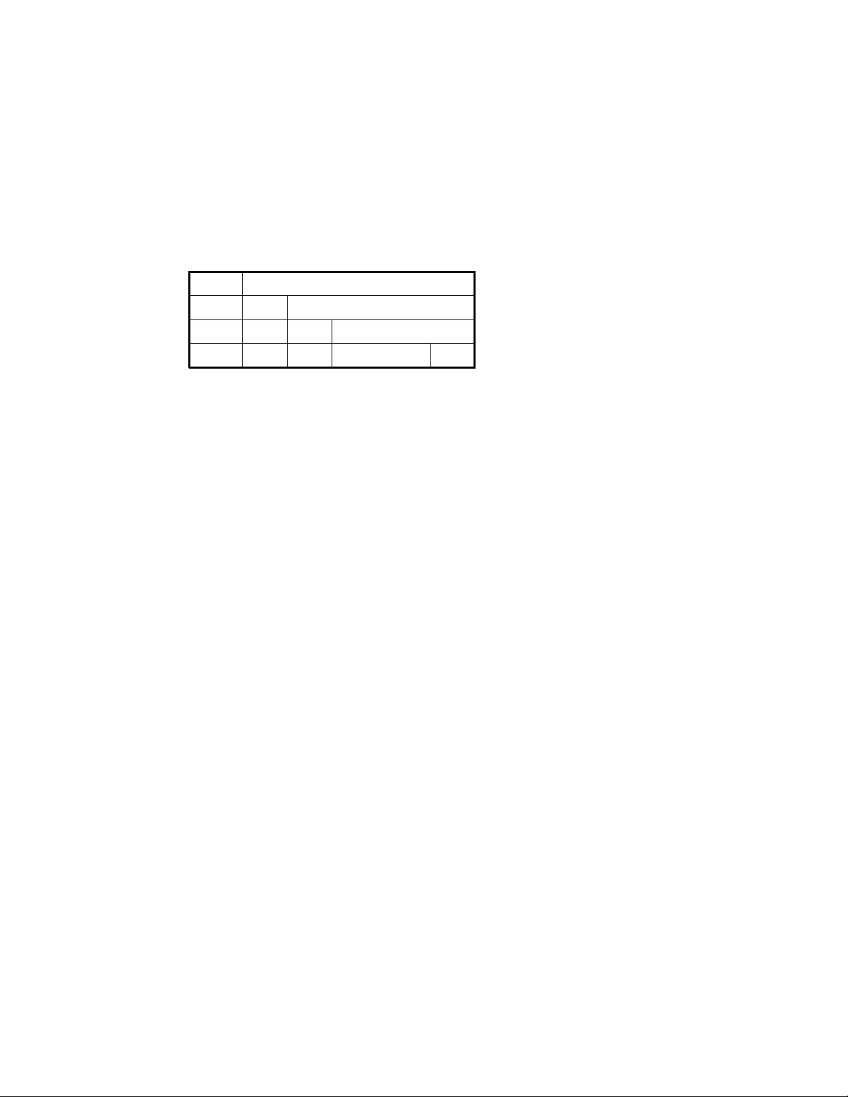
As shown in Figure 1–1, Alpha instructions are all 32 bits in length. Th ere are four major
instruction format classes that contain 0, 1, 2, or 3 register fields. All formats have a 6-bit
opcode.
Figure 1–1: I nstruct ion Format Overview
031 26 25 2120 16 15 5 4
NumberOpcode
PALcode Format
Function RCRB
Disp
Disp
Branch Format
Memory Format
Operate Format
Opcode
Opcode
Opcode
RA
RA
RA
RB
• PALcode instructi ons specify, in the function code field, one of a few dozen complex
operations to be performed .
• Conditional branch instructions test register Ra and specify a signed 21-bit PC-rela-
tive longword target displacement. Subroutine calls put the return address in register
Ra.
• Load and store instructions move bytes, words, longwords, or quadwords between
register Ra and memory, using Rb plus a signed 16-bit displacement as the memory
address.
• Operat e in stru ctions for floating-point and integer operations are both represented in
Figure 1–1 by the operate format ill ustr ation and are as follows:
– Word and byte sign-extension operators.
– Floating-point operations use Ra and Rb as source registers and write the result in
register Rc. There is an 11-bit extended opcode in the function field.
– Integer operations use Ra and Rb or an 8-b it literal as the source operand, and write
the result in registe r Rc.
– Integer operate instructions can use the Rb field and part of the function field to
specify an 8-bit litera l. There is a 7-bit extended opco de i n the func tion field.
1.4 Instruction Overview
PALcode Instructions
As described in Section 1.1, a Privileged Architecture Library (PALcode) is a set of subroutines that is specific to a particular Alpha operating-system implem entation. These subroutines
can be invoked by hardware or by software CALL_PAL instructions, which use the function
field to vector to the specifie d subroutine.
1–4 Alpha Architecture Handbook
Page 21

Branch Instruct i ons
Conditional branch i nstruc tions can tes t a reg ister fo r p ositiv e/negat ive or fo r zero /nonze ro,
and they can test inte ge r registe r s for e ven/odd. Uncondition al branc h ins tru ctions c a n write a
return address into a register.
There is also a calculated jump instruction that branches to an arbitrary 64-bit address in a
register.
Load / S tore Instruction s
Load and store instruc tion s m ove 8-bit, 16-bit, 32-bit, or 64-bit a ligne d qu an tities from a nd to
memory. Memory addresses are flat 64-bit virtual addresses with no segmentation.
The VAX floating-point load/store instructions swap words to give a consistent register format
for floating-point operations.
A 32-bit integer datum is placed in a register in a canonical form that makes 33 copies of the
high bit of the datum. A 32 -bit floating -po int datum is pla c ed in a regis ter in a canoni cal fo rm
that extends the exponent by 3 bits and extends the fraction with 29 low-order zeros. The 32bit operates preserve these canonical forms.
Compilers, as directed by user decl arations, can generate any mixture of 32-bit and 64-bit operations. The Alpha architecture has no 32/64 mode bit.
Integer Operate Instructions
The integer operate instructions manipulate full 64-bit values and include the usual assortment
of arithmetic, compare, logical, and shift instructions.
There are just three 32-bit inte ger ope rates: add , subtrac t, and mul tiply. The y diffe r from the ir
64-bit counterparts only in overflow detection and in producing 32-bit canonical results.
There is no integer divide instr uction.
The Alpha architectur e also suppor ts the following additional operations:
• Scaled add/subtract instructions for quick subscript calculation
• 128-bit multiply for division by a constant, and multiprecision arithmetic
• Conditional move instructions for avoiding branch instructions
• An extensive set of in-register byte and word manipul ation instructions
• A set of multimedia instructions that support gr aphics and video
Integer overflow tr ap enab le is en cod ed in th e fun ction field o f ea ch instruct ion, ra ther t han
kept in a global state bit. Thus, for example, both ADDQ/V and ADDQ opcodes exist for specifying 64 -bi t ADD w ith a nd w itho ut ov erfl ow check in g. Tha t m akes it eas ier to pi pel ine
implementations.
Introduction 1–5
Page 22

Floating-Point Operate Instructions
The floating-point operate instructions include four complete sets of VAX and IEEE arithmetic instructions, plus instructions for performing conversions between floating-point and
integer quantiti es.
In addition to the ope ratio ns f ound in co nventional RISC arc hitec tur es, A lpha inc lud es con ditional move instructions for avoiding branches and merge sign/exponent instructions for simple
field manipulation.
The arithmetic trap enables and rounding mode are encoded in the function field of each
instructi on, rather t han kept in g lobal stat e bits. Tha t makes it eas ier to pipe line
implementations.
1.5 Instruction Set Characteristics
Alpha instruction set char acteristics are as follows:
• All instructions are 32 bits long and have a regular for mat.
• There are 32 integer registers (R0 through R31), each 64 bits wide. R31 reads as zero,
and writes to R31 are ignored.
• All integer data manipulation is between intege r register s, with up to two variable regis-
ter source operands (one may be an 8-bit liter al) and one register destination operand.
• There are 32 floating-point registers (F0 through F31), each 64 bits wide. F31 reads as
zero, and writes to F31 are ignored.
• All floating-point data manipulation is between floating-point registers, with up to two
register source opera nds a nd one register destination operand.
• Instructions can move data in an integer register file to a f loating-point register file, and
data in a floating-point register file to an integer register file. The instructions do not
interpret bits in the register files and do not access memory.
• All mem ory referenc e instructions are of the load/store type that moves data between
registers and memory.
• There are no branch condition codes. Branch instructions test an integer or floating-
point register value , whic h may be the result of a previous compare.
• Integer and logical instructions operate on quadwords.
• Floating-point instructions operate on G_floating, F_floating, and IEEE extended, dou-
ble, and single operands. D_floating "format compatibility," in which binary files of
D_floating numbers may be processed, but without the last 3 bits of fraction precision,
is also provided.
• A minimal number of VAX compatibility instructions are included.
1.6 Terminology and Conventions
The following sections describe the terminology and conventions used in this book.
1–6 Alpha Architecture Handbook
Page 23

1.6.1 Numbering
All numbers are decima l unle ss oth erwis e ind icate d. Whe r e there is am bigu ity, numbe rs other
than decimal are indicated with the name of the base in subscript form, for example , 10
1.6.2 Securi ty Holes
A security hole is an erro r o f commission, omission, or oversight in a sy ste m tha t allows protection mechanisms to be bypassed.
Security holes exist when unprivileged software (software running outside of kernel mode)
can:
• Affect the operation of another process without authorization from the operating sys-
tem;
• Amplify its privilege without authorization from the operating system; or
• Communicate with another process, either overtly or covertly, without authorization
from the operating system.
The Alpha architecture has been designed to contain no a rchitectura l security holes. Hardwar e
(processors, buses, controllers, and so on) and software should likewise be designed to avoid
security holes.
16.
1.6.3 UNPREDICTABLE and UNDEFINED
The terms UNPREDIC TAB L E and UNDE FINE D are used through out this book. Their meanings are quite different and must be carefully distinguished.
In particular, only privileged software (software running in kernel mode) can trigger UNDEFINED oper ati ons. U npr ivil eg ed softwa r e cannot trigger UN DEF I NE D op era tion s. How e ver,
either privileged or unprivileged software can trigger UNPREDICTA BLE results or
occurrences.
UNPREDICTABLE results or occur rences do not disrupt the basic operatio n of the processor;
it continues to exe c ute instr uc tion s in its nor m al manner. In contras t, UND EF I NED ope r ation
can halt the processor or cause it to lose information.
The terms UNPREDICTABLE and UNDEFINED can be further described as follows:
UNPREDICTABLE
• Results or occurrences specified as UNPREDICTABLE may vary from moment to
moment, implementation to implementation, and instruction to instruction within
implementations. Software can never depend on results specified as UNPREDICTABLE.
• An UNPREDICTABLE result may acquire an arbitrary value subject to a few con-
straints. Such a result may be an arbitrary function of the input operands or of any state
information that is accessible to the process in its current access mode. UNPREDICTABLE results may be unchanged from their previous values.
Introduction 1–7
Page 24

Operations that produc e UNPREDICTABLE results may also produce exceptions.
• An occurrence specified as UNPREDICTABLE may happen or not based on an arbi-
trary choice function. The choice function is subject to the same constraints as are
UNPREDICTABLE results and, in particular, must not constitute a security hole.
Specifically, UNPREDICTABLE results must not depend upon, or be a function of,
the contents of memory locations or registers that are inaccessible to the current
process in the current access mode.
Also, operations that may produce UNPREDICTABLE results must not:
– Write or modify the contents of memory locations or registers to which the current
process in the current access mode does not have access, or
– Halt or hang the system or any of its components.
For example, a security hole would exist if some UNPREDICTABLE result depended
on the value of a register in another process, on the contents of processor temporary
registers left behind by some previously running process, or on a sequence of actions
of different processe s.
UNDEFINED
• Operations specified as UNDEFINED may vary from moment to moment, implementa-
tion to implementation, and instruction to instruction within implementations. The
operation may vary in eff ect from nothing to stopping syst em opera tion.
• UNDEFINED operations may halt the processor or cause it to lose information. How-
ever, UNDEFI NED operations must not cause the processor to hang, that is, reach an
unhalted state from which there is no transition to a normal state in which the machine
executes instructions.
1.6.4 Ranges and Extents
Ranges are specified by a pair of numbers separated by two periods and are inclusive. For
example, a range of integers 0..4 includes the integers 0, 1, 2, 3, and 4.
Extents are specified by a pair of numbers in angle brackets separated by a colon and are inclusive. For example, bits <7: 3> specif y an extent of bits including bits 7, 6, 5, 4, and 3.
1.6.5 ALIGNED and UNALIGNED
In this document the term s A LIGNE D and NATU RA LLY ALIG N ED are u sed in terchange ably to refer to data objects that are powers of two in size. An aligned datum of size 2**N is
stored in memory at a byte address that is a multiple of 2**N, that is, one that has N low-order
zeros. Thus, an aligned 64-byte stack frame has a memory address that is a multiple of 64.
If a datum of size 2**N is stored at a byte address that is not a multiple of 2**N, it is called
UNALIGNED.
1–8 Alpha Architecture Handbook
Page 25

1.6.6 Must Be Zero (MBZ)
Fields specified as Must be Zero (M BZ) must neve r be filled by software with a non -zero
value. These field s may be u sed at som e fut ure tim e. If the pro cess or en co unters a no n-zero
value in a field specified as MBZ, an Illegal Operand exception occurs.
1.6.7 Read As Zero (RAZ)
Fields specified as Read as Zero (RAZ) return a zero when read.
1.6.8 Sh ould Be Zer o (SBZ)
Fields specified as Should be Zero (SB Z) sho uld be filled by softw are with a zero va lue. Non zero values in SBZ fields produce UNPREDICTABLE results and may produce extraneous
instruction-issue delays.
1.6.9 Ignore (IGN)
Fields specified as Ignore (IGN) are ignored when written.
1.6.10 Implementation Depe ndent (IMP )
Fields specified as Implementation Dependent (IMP) may be used for implementation-specific
purposes. Each im plem e ntation must document f ully the beh avior of all fi elds m arke d as IMP
by the Alpha specification.
1.6.11 Illustration Con ventions
Illustrations that depict registers or memory follow the co nvention that increas ing addresses
run right to left and top to bottom.
1.6.12 Macro Code Example Conventions
All instructions in macro c ode example s a re e ither listed in Cha pter 4 or are stylize d code
forms found in Section A.4.6.
Introduction 1–9
Page 26

Page 27

2.1 Addressing
70
:A
The basic addre ssa ble un it in the Al pha archite c ture is the 8- bit by te . Vir tual ad dr esse s are 64
bits long. An im pl em en ta tio n m ay support a sm a ller vir tual a dd r es s sp ace . The minimu m vir tual address size is 43 bits.
Virtual addresses as seen by the program are translated into physical memory addresses by the
memory ma n agem en t mechanism.
Although th e da ta types in Section 2.2 ar e de sc ribe d in te rms of little -e ndi an byte addressing,
implementations may also include big -endian addressing support, as describe d in Sec tion 2 .3.
All current implementations have some big-endian support.
Chapter 2
Basic Architecture
2.2 Data Types
Following are descriptions of the Alpha architecture data types.
2.2.1 Byte
A byte is 8 contiguous bits starting on an add ressable byte b oundary. Th e b its are numbered
from right to left, 0 through 7, as shown in Figure 2–1.
Figure 2–1: B yte Format
A byte is specified by its address A. A byte is an 8-bit value. The byte is only supported in
Alpha by the load, store, sign-e xtend, extract, mask, insert, and zap instructions.
2.2.2 Word
A word is 2 contiguous bytes starting on an arbitrary byte boundary. The bits are numbered
from right to left, 0 through 15, as shown in Figure 2–2.
Basic Architecture 2–1
Page 28
Figure 2–2: Wor d Format
A word is specified by its address, the address of the byte containing bit 0.
A word is a 16-bit val ue. Th e wor d is only supported in Alpha by th e lo ad, sto re, sign- exte nd,
extract, mask, and inser t instructions.
2.2.3 Longword
A longword is 4 contiguous bytes starting on an arbitrary byte boundary. The bits are num-
bered from right to left, 0 through 31, as shown in Figure 2–3.
Figure 2–3: L ongword Format
015
:A
031
:A
A longword is specified by its ad dress A, the add ress of the byte conta ining bit 0. A longword
is a 32-bit value.
When interpreted arithmetically, a longword is a two’s-complemen t integer with bits of
increasing significance from 0 through 30. Bit 31 is the sign bit. The longword is only supported in Alp ha by sign-ext ended lo ad an d store in struc tions and by lo ngwor d arithme tic
instructions.
Note:
Alpha implementations will impose a significant performance penalty when accessing
longword operands that are not naturally aligned. (A naturally aligned longword has zero
as the low-order two bits of its address.)
2.2.4 Quadword
A quadword is 8 contiguous bytes starting on an arbitrary byte boundary. The bits are numbered from right to left, 0 through 63, as shown in Figure 2–4.
Figure 2–4: Quadword Format
63
0
:A
2–2 Alpha Architecture Handbook
Page 29
A quadword is specified by its address A, the address of the byte containing bit 0. A quadw ord
is a 64-bit value. When interpreted arithmetically, a q uadw ord is either a tw o’s-comp lement
integer with bits of increasing significance from 0 through 62 and bit 63 as the sign bit, or an
unsigned integer with bits of increasing significance from 0 through 63.
Note:
Alpha implementations will impose a significant performance penalty when accessing
quadword operands that are not naturally aligned. (A naturally aligned quadword has zero
as the low-order three bits of its address.)
2.2.5 VAX Floating- Poi nt F ormats
VAX floating-point numbers are stored in one set of formats in memory and in a second set of
formats in r egisters. The f loating-poin t lo ad a nd s tor e instructi ons c onv e rt be tw een these formats purely by rearranging bits; no rounding or range-checking is done by the load and store
instructions.
2.2.5.1 F_floating
An F_floating datum is 4 c on tiguous byte s in m em o ry sta rting on an arbit rar y by te bou nd ary.
The bits are labeled from right to le ft , 0 thro ugh 31, as shown in Figure 2–5 .
Figure 2–5: F_f loating Datum
31
16 14
S
715
60
Frac. HiFraction Lo :AExp.
An F_floating operand oc cupie s 64 bits in a floati ng r egister, left-justified in the 64- bi t reg is-
ter, as shown in Figure 2–6.
Figure 2–6: F_floating Register Format
52 51 29 28
S
Exp. Fraction 0 :Fx
The F_ f lo a ti ng lo a d instruction re o r der s bits on the way in from m e mory, ex p a nd s t he e xp onent from 8 to 11 bits, and sets the low-order fraction bits to zero. This produces in the register
an equiv a lent G_floating num be r suitable f or e ith e r F_ f loating or G _f lo a tin g o pe r ations. Th e
mapping from 8-bit memory-format exponents to 11-b it register-forma t exponents is shown in
Table 2–1. This mapping preserves both normal values and exceptional values.
063 62
Basic Architecture 2–3
Page 30

Table 2–1: F_floating Load Exponent Mapping (M AP_F)
Memory <14:7> Register <62:52>
1 1111111 1 000 1111111
1 xxxxxxx 1 000 xxxxxxx (xxxxxxx not all 1’s)
0 xxxxxxx 0 111 xxxxxxx (xxxxxxx not all 0’s)
0 0000000 0 000 0000000
The F_floa ting stor e ins truction reord ers regis ter b its on the w ay to m emo ry an d does no
checking of the low-order fraction bits. Register bits <61:59> and <28:0> are ignored by the
store instructi on.
An F_floating datum is specified by its address A, the address of the byte containing bit 0. The
memory form of an F_floating datum is sign magnitude with bit 15 the sign bit, bits <14:7> an
excess-128 binary exponent, and bits <6:0> and <31:16> a normalized 24-bit fraction with the
redundant m o st si gnificant fra ction bit not repr e sented. Within the f r acti on, bits of increa si ng
significance are from 16 through 31 and 0 through 6. The 8-bit exponent field encodes the values 0 thr o ug h 255. A n e xp on e nt va lu e o f 0, togeth e r with a sig n bit of 0, is ta k e n t o indicate
that the F_floating datum has a value of 0.
If the result of a VAX floating-point format instruction has a value of zero, the instruction
always produces a datum with a sign bit of 0, an exponent of 0, and all fraction bits of 0. Expo-
nent values of 1..255 indicate true binary exponents of –127..127. An exponent value of 0,
together with a sign bit of 1, is taken as a reserved operand. Floating-point instructions processing a reserved operand take an arithmetic exception. The value of an F_floating datum is in
the approximate range 0.29*10**–38 through 1.7*10** 38. The precision of an F_floating
datum is approximately one part in 2**23, typically 7 decimal digits. See Section 4.7.
Note:
Alpha implementations will impose a significant performance penalty when accessing
F_floating operands that are not naturally aligned. (A naturally aligned F_floating datum
has zero as the low-order two bits of its address.)
2.2.5.2 G_floating
A G_floating datum in memory is 8 contiguous bytes starting on an arbitrary byte boundary.
The bits are labeled from right to le ft , 0 thro ugh 63, as shown in Figure 2–7.
Figure 2–7: G_floating Datum
16 14
31
2–4 Alpha Architecture Handbook
15
S
43
Exp. Frac.HiFraction Midh :A
0
:A+4Fraction MidlFraction Lo
Page 31

A G_floating operand occupie s 64 bits in a floating register, arranged as shown in Figure 2–8.
0
Figure 2–8: G_f loating Register Format
63 62
S
52 51
Exp. Fraction Hi Fraction Lo :Fx
32 31
A G_floating datum is specifie d by its ad dress A, the add ress of the byte co nta ining bit 0. The
form of a G_floating datum is sign magnitude w it h bit 15 the s ign bit, bits < 14: 4> an excess1024 binary exponent, and bits <3:0> and <63:16> a normalized 53-bit fraction with the redundant most significant fraction bit not represented. Within the fraction, bits of increasing
significance are from 48 through 63, 32 through 47, 16 through 31, and 0 through 3. The 11-bit
exponent field encodes the values 0 through 2047. An exponent value of 0, together with a sign
bit of 0, is taken to indicate that the G_fl oating datum has a value of 0.
If the result of a floating-point instruc tion ha s a value of zero, the instructio n alw ays prod uces
a datum with a sign bit of 0, an exponent of 0, and all fraction bits of 0. Exponent values of
1..2047 indicate true binary exponents of –1023..1023. An exponent value of 0, together with a
sign bit of 1, is ta ke n a s a r es erv ed oper a nd. F lo at ing-point instru cti ons pr oce ssin g a rese rve d
operand take a user-visible arithmetic exception. The value of a G_floating datum is in the
approximate range 0.56*1 0**–308 through 0.9*10** 308. The precis ion of a G_floating dat um
is approximately one part in 2**52, typically 15 decimal digits. See Section 4.7.
Note:
Alpha implementations will impose a significant performance penalty when accessing
G_floating operands that are not naturally aligned. (A naturally aligned G_floating datum
has zero as the low-order three bits of its address.)
2.2.5.3 D_floating
A D_floating datum in memory is 8 contiguous bytes starting on an arbitrary byte boundary.
The bits are labeled from right to le ft , 0 thro ugh 63, as shown in Figure 2–9.
Figure 2–9: D _floating Datum
31
A D_floating operand occupie s 64 bits in a floa ting register, arranged as shown in Figure 2–10.
Figure 2–10: D_floating Register Format
63 62
S
55 54
Exp. Fraction Midh Fraction Midl Fraction Lo :Fx
Frac. Hi
16 14
S
48 47 32 31 16 15
715
60
Exp. Frac.HiFraction Midh :A
:A+4Fraction MidlFraction Lo
0
Basic Architecture 2–5
Page 32

The reorderin g of bits re quir ed f or a D_ floa ting lo ad or store is ide ntica l to th at re quir ed f or a
G_floating load or store. The G_floating load and store instructions are therefore used for loading or storing D_floating data.
A D_floating datum is specifie d by its ad dress A, the add ress of the byte co nta ining bit 0. The
memory form of a D_floating datum is identical to an F_floating datum except for 32 additional low significance fraction bits. Within the fraction, bits of increasing significance are
from 48 through 63, 32 through 47, 16 th rough 31, and 0 through 6. The exponent conventions
and approximate range of values is the same for D_floating as F_floating. The precision of a
D_floating datum is approximately one part in 2**55, typically 16 decimal digits.
Notes:
D_floating is not a fully supported data type; no D_floating arithmetic operations are
provided in the architecture. For backward compatibility, exact D_floating arithmetic may
be provided via software emulation. D_floating "format compatibility"in whic h binary files
of D_floating numbers may be processed, but without the last three bits of fraction
precision, can be obtained via conversions to G_floating, G arithmetic operations, then
conversion back to D_floating.
Alpha implementations will impose a significant performance penalty on access to
D_floating operands that are not naturally aligned. (A naturally aligned D_floating datum
has zero as the low-order three bits of its address.)
2.2.6 IEEE Fl oating-Point Formats
The IEEE standard for binary floating-point arithmetic, ANSI/IEEE 754-1985, defines four
floating-point form at s in two gr ou ps, b a sic a nd e x te nd ed , e ach ha vin g tw o widths, s ing le and
double. The Alpha architecture supports the basic single and double formats, with the basic
double format serving as the extended single for ma t. The values repre sentable within a format
are specified by using three integer parameters:
• P – the number of fraction bits
• Emax – the maximum exponent
• Emin – the minimum exponent
Within each format, only the following entities are permitted:
• Numbers of the form (–1)**S x 2**E x b(0).b(1)b(2)..b(P–1) where:
– S = 0 or 1
– E = any integer between Emin and Emax, inclusiv e
– b(n) = 0 or 1
• Two infinities – positive and negative
• At least one Signaling NaN
• At least one Quiet NaN
NaN is an acronym for Not-a-Num ber. A NaN is an IEEE flo ating -point bit pattern that represents something other than a number. NaNs come in two forms: Signaling NaNs and Quiet
2–6 Alpha Architecture Handbook
Page 33

NaNs. Signaling NaNs are used to provide values for uninitialized variables and for arithmetic
enhancements. Quiet NaNs provide retrospective diagnostic information regarding previous
invalid or un avai la ble data an d re sults . Signa lin g Na N s signal an inval id op era tio n when they
are an operand to an arithmetic instruction, and may generate an arithmetic exception. Quiet
NaNs propagate through almost every operation without generating an arithmetic exception.
Arithmetic with the infinities is handled as if the operands were of arbitrarily large magnitude.
Negative inf in ity is less than e ve ry f init e n um ber ; p ositive infin ity i s greater than every finite
number.
2.2.6.1 S_Floating
An IEEE single -pre cision, or S_float ing, da tum occupies 4 contiguous bytes in me m ory sta r ting on an arbitrary byte boundary. The bits ar e labeled from right to left, 0 through 31, as
shown in Figure 2–11.
Figure 2–11: S_floating Datum
3031 22
Exp. Fraction :A
S
An S_floating operand oc cupie s 64 bits in a floati ng r egister, left-justified in the 64- bi t reg is-
ter, as shown in Figure 2–12.
23
0
Figure 2–12: S_f loating Register Format
52 51 29 28
S
Exp. Fraction 0 :Fx
The S_floating load instruction reorders bits on the way in from memory, expanding the exponent from 8 to 11 bits, and sets the low-order fraction bits to zero. This produces in the register
an equiv al ent T_floating number , suitable f or e ith e r S_ f loating or T_ fl oating opera tio ns. The
mapping from 8-bit memory-format exponents to 11-b it register-forma t exponents is shown in
Table 2–2.
Table 2–2: S_floating Load Exponent Mapping (MAP_S)
Memory <30:23> Register <62:52>
1 1111111 1 111 1111111
1 xxxxxxx 1 000 xxxxxxx (xxxxxxx not all 1’s)
0 xxxxxxx 0 111 xxxxxxx (xxxxxxx not all 0’s)
0 0000000 0 000 0000000
063 62
Basic Architecture 2–7
Page 34

This mapping preserves both norma l valu es and exceptiona l va lues. Note tha t the map ping for
all 1’s differs from th a t of F _f loating load, s inc e fo r S_floating all 1’s is a n exc e ptio na l value
and for F_floating all 1’s is a normal value.
The S_floa ting stor e ins truction reord ers regis ter b its on the w ay to m emo ry an d does no
checking of the low-order fraction bits. Register bits <61:59> and <28:0> are ignored by the
store instruction. The S_floating load instruction does no checking of the input.
The S_floa tin g sto r e i nstruction does no checkin g of th e da ta; the p rec e din g op e rati on should
have specified an S_floating result.
An S_floating datum is specified by its address A, the address of the byte containing bit 0. The
memory fo rm of an S _ f loa ti ng d a tum is sign ma gn itu de with bit 31 t he si gn bit, bits <30 :2 3>
an excess-127 binary exponent, and bits <22:0> a 23-bit fraction.
The value (V ) o f an S_floating num b e r is inferred from its constitu e nt sig n ( S ), exp one nt (E ),
and fraction (F) field s as follows:
• If E=255 and F<>0, then V is NaN, regardless of S.
• If E=255 and F=0, then V = (–1)**S x Infinity.
• If 0 < E < 255, then V = (–1)**S x 2**(E–127) x (1.F).
• If E=0 and F<>0, then V = (–1)**S x 2**(–126) x (0.F).
• If E=0 and F=0, then V = (–1)**S x 0 (zero).
Floating-point operat ion s on S_floatin g nu m be rs m a y take an arith me tic exc e ptio n f or a va riety of reasons, including invalid operations, overflow, underflow, division by zero, and inexact
results.
Note:
Alpha implementations will impose a significant performance penalty when accessing
S_floating operands that are not naturally aligned. (A naturally aligned S_floating datum
has zero as the low-order two bits of its address.)
2.2.6.2 T_floating
An IEEE double-precision, or T_floating, datum occupies 8 contiguous bytes in memory starting on an arbitrary byte boundary. The bits ar e labeled from right to left, 0 through 63, as
shown in Figure 2–13.
Figure 2–13: T _floating Datum
31 30 19
Exponent
S
20
Fraction Lo
Fraction Hi
0
:A
:A+4
2–8 Alpha Architecture Handbook
Page 35

A T_floating operand occupie s 64 bits in a floating register, arranged as shown in Figure 2–14.
0
Figure 2–14: T_floating Register Format
63 62
S
52 51
Exp. Fraction Hi Fraction Lo :Fx
32 31
The T_floating load instruction performs no bit reordering on input, nor does it perform checking of the input data.
The T_floating store instruction performs no bit reordering on output. This instruction does no
checking of the data; the preceding operation should have specified a T_floating result.
A T_floating datum is spe cif ied by its addr es s A, the address of the byte containin g bit 0. Th e
form of a T_floating da tum is sign ma gnitu de with bit 63 the si gn bit, bits <6 2:52> a n e xc ess1023 binary exponent, and bits <51:0> a 52-bit fraction .
The value (V) of a T_floating number is inferred from its constituent sign (S), exponent (E),
and fraction (F) field s as follows:
• If E=2047 and F<>0, then V is NaN, regardless of S.
• If E=2047 and F=0, then V = (–1)**S x Infinity .
• If 0 < E < 2047, then V = (–1)**S x 2**(E–1023) x (1.F).
• If E=0 and F<>0, then V = (–1)**S x 2**(–1022) x (0.F).
• If E=0 and F=0, then V = (–1)**S x 0 (zero).
Floating-point operatio ns on T_f lo at ing num b ers m ay ta k e a n ar ithmetic except ion for a va riety of reasons, including invalid operations, overflow, underflow, division by zero, and inexact
results.
Note:
Alpha implementations will impose a significant performance penalty when accessing
T_floating operands that are not naturally aligned. (A naturally aligned T_floating datum
has zero as the low-order three bits of its address.)
2.2.6.3 X_Floating
Support for 128-bit IEEE extended-precision (X_flo at) floating-point is initially provided
entirely through software. This section is included to preserve the intended consistency of
implementation with other IEEE floating-point data types, should the X_float data type be supported in future hardware .
An IEEE e xte nd e d-pr e cision, or X_f loa t ing , da tum o c cupie s 16 c on tiguous byte s in m e mor y,
starting on an arbitrary byte boundary. The bits are labeled from right to left, 0 through 127, as
shown in Figure 2–15.
Basic Architecture 2–9
Page 36

Figure 2–15: X _floating Datum
48 4763 62
Fraction_low
S Exponent Fraction_high
An X_floating datum occupie s two consecutive even/od d floating-point registe rs (such as
F4/F5), as shown in Figure 2–16.
Figure 2–16: X_floating Register Format
127 064 63
126 112 111
S
Exponent Fraction_high Fraction_low
Fn OR 1 Fn
An X_floating datum is specified by its address A, the address of the byte containing bit 0. The
form of an X_floating datum is sign magnitude with bit 127 the sign bit, bits <126:112> an
excess–16383 binary expo nent, and bits <111:0> a 112-bit fraction.
The value (V) of an X_f loa tin g num ber is inf err ed from its c onsti tue nt sign (S) , expo nent (E ),
and fraction (F) field s as follows:
0
:A
:A+8
• If E=32767 and F<>0, then V is a NaN, regardless of S.
• If E=32767 and F=0, then V = (–1)**S x Infinity .
• If 0 < E < 32767, then V = (–1) **S x 2**(E–16383) x (1.F).
• If E=0 and F<> 0, then V = (–1)**S x 2**(–16382) x (0.F).
• If E = 0 and F = 0, then V = (–1)**S x 0 (zero ).
Note:
Alpha implementations will impose a significant performance penalty when accessing
X_floating operands that are not naturally aligned. (A naturally aligned X_floating datum
has zero as the low-order four bits of its address.)
X_Floating Big-Endian Formats
Section 2.3 describes Alpha support for big-endian data types. It is intended that software or
hardware implementation for a big-endian X_float data type comply with that support and have
the following formats .
2–10 Alpha Architecture Handbook
Page 37

Figure 2–17: X _floating Big-Endian Datum
Byte
0
A:
S Exponent Fraction_high
A+8:
Fraction_low
Figure 2–18: X _floating Big-Endian Register Format
Byte Byte
0 15
S Exponent Fraction_high Fraction_low
Fn OR 1 Fn
2.2.7 Longword Integer Format in Floating-P oin t Unit
A longword integer operand occupies 32 bits in memory, arranged as shown in Figure 2–19.
Byte
15
Figure 2–19: L ongword Integer Datum
3031
S
Integer :A
A longwo rd integer oper a nd o ccupies 64 b its i n a fl oating registe r, arranged as shown in Fig-
ure 2–20.
0
Figure 2–20: L ongword Integer Floating-Register Format
59 58
61
xxx Integer 0 :Fx
S
I
29 28
There is no explicit longword load or store instruction; the S_floating load/store instructions
are used to move lo ngw or d da ta into or out o f the f loa ting registe r s. The regi ste r bits <61:59>
are set by the S_floating load exponent mapping. They are ignored by S_floating store. They
are also ignored in ope ran ds of a longword integer oper ate ins tru cti on, a nd they a r e set to 000
in the result of a longword operate instruction.
The registe r for ma t bi t <62> "I" in Fi gure 2–2 0 is part of the In te ger field in F ig ur e 2–1 9 a nd
represents the high-order bit of that field.
063 62
Basic Architecture 2–11
Page 38

Note:
0
Alpha implementations will impose a significant performance penalty when accessing
longwords that are not naturally aligned. (A naturally aligned longword datum has zero as
the low-order two bits of its addr ess .)
2.2.8 Quadword Integer Format in Floating-Point Unit
A quadword integer operand occupi es 64 bits in memory, arranged as shown in Figure 2–21.
Figure 2–21: Quadword Integer Datum
31 30
Integer Lo
0
:A
S
Integer Hi
:A+4
A quadword intege r o pera nd oc cupie s 64 bits in a f loating register, ar rang ed as shown in Fig-
ure 2–22.
Figure 2–22: Quadword Integer Floating-Register Format
63 62
S
Integer Hi Integer Lo :Fx
There is no explicit quadwo rd lo ad or store instr uc ti on ; the T_floa tin g load/sto re in structions
are used to move qua dwo rd data b etw een mem ory a nd the floatin g registers. (The I TOFT and
FTOIT are used to move quadword data between integer and floa ting registers.)
The T_floating load instruction pe rforms no bit r eordering on input. The T_f loating store
instruction performs no bit reordering on output. This instruction does no checking of the data;
when used to store quadwords, the preceding operation shou ld have specified a quadword
result.
32 31
Note:
Alpha implementations will impose a significant performance penalty when accessing
quadwords that are not naturally aligned. (A naturally aligned quadword datum has zero as
the low-order three bit s of its address.)
2.2.9 Data Types with No Hardware Support
• The following VAX data types are not directly supported in Alpha hardware. Octaword
• H_floating
• D_floating (except load/store and convert to/from G_floating)
• Variable-Length Bit Field
• Character String
2–12 Alpha Architecture Handbook
Page 39

• Trailing Numeric String
• Leading Separate Numeric String
• Packed Decimal String
2.3 Big -Endian Addressing Suppo rt
Alpha implementation s may include optional big-endian addressing support.
In a little-endia n machine, the bytes within a quadword are numbered right to left:
Figure 2–23: L ittle-Endian Byte Addressing
5432167 0
In a big-endian machine, they are numbere d left to right:
Figure 2–24: B ig-Endian Byte Addressing
2345610 7
Bit numbering within bytes is not affected by the byte numbering convention (b ig- endian or little-endian).
The format for the X_floating big-endian data type is shown in Section 2.2.6.3.
The byte numbe r ing convention does not matter when accessing comp lete aligned quadw ords
in memory. However, the numbering convention does matter w hen accessing smaller or
unaligned quantities, or when manipulating data in registers, as follows:
• A quadword load or store of data at location 0 moves the same eight bytes under both
numbering conventions. However, a longword load or store of data at location 4 must
move the leftmost half of a quadword under the little-endian convention, and the rightmost half under the big-endian convention. Thus, to support both conventions, the convention being used must be known and it must affect longword load/store operations.
• A byte extract of byte 5 from a quadwor d of data into the low byte of a register requires
a right shift of 5 bytes under the little-endian convention, but a right shift of 2 bytes
under the big-endian conve ntion.
• Manipulation of data in a register is almost the same for both conventions. I n both, inte-
ger and floating-point data have their sign bits in the leftmost byte and their least significant bit in the rightmost byte, so the same integer and floating-point instructions are
Basic Architecture 2–13
Page 40

used unchanged for both conventions. Big-endian charac te r str ings have their most significant character on the left , while litt le-endian str ings have their most signific ant character on the right.
• The compare byte (CMPBGE) instruction is neutral about direction, doing eight byte
compares in parallel. However, following the CMPBGE instruction, the code is different that examines the byte mask to determine which string is larger, depending on
whether the rightmost or leftmost unequal byte is used. Thus, compilers must be
instructed to generate somewhat different code sequences for the two conventions.
Implementations that include big-endian support must supply all of the following features:
• A means at boot time to choose the byte numbering convention. The implementation is
not required to support dynamically changing the convention during program execution. The chosen convention applies to all code executed, both operating-system and
user.
• If the big-endian convention is chosen, the longword-length load/store instructions
(LDF, LDL, LDL_L, LDS, STF, STL, STL_C, STS) invert bit va<2> (bit 2 of the virtual address). This has the effect of accessing the half of a quadword other than the half
that would be accessed under the little-endian convention.
• If the big-endian convention is chosen, the word-length load instruction, LDWU,
inverts bit s va<1:2> (bits 1 and 2 of the virtual address) . This has the effect of accessing
the half of the longword that would be accessed under the little-endian convention.
• If the big-endian convention is chosen, the byte-length load instruction, LDBU, inverts
bits va<0:2> (bits 0 through 2 of the virtual address). This has the effect of accessing
the half of the word that would be accessed under the little-endian convention.
• If the big-endian convention is chosen, the byte manipulation instructions (EXTxx,
INSxx, MSKxx) invert bits Rbv<2:0>. This has the effect of changing a shift of 5 bytes
into a shift of 2 bytes, for example.
The instruction stream is always considered to be little-endian, and is ind epen de nt of the ch osen byte numbering convention. Com pilers, linkers, and debuggers must be aware of this when
accessing an instruction stream using data-stream load/store instructions. Thus, the rightmost
instruction in a quadword is always executed first and always has the instruction-stream
address 0 MOD 8. The same bytes accessed b y a l ongword loa d/store i nstruction hav e data stream address 0 M OD 8 un der th e little-endi an conve ntion, and 4 MOD 8 under the bigendian convention.
Using either byte numbering convention, it is sometim es necessary t o access d ata that originated on a machine that used the other convention. When this occurs, it is often necessary to
swap the bytes within a datum. See Section A.4. 3 for a suggested code sequence.
2–14 Alpha Architecture Handbook
Page 41

3.1 Alpha Registers
Each Alpha processor has a set of reg isters that h old the current p roc essor state. If an Alph a
system conta ins mu ltiple Alpha proce ssors, th ere are m ultiple per-proc essor se ts of thes e
registers.
3.1.1 Program Counter
The Program Counter (PC) is a special register that addresses the instruction stream. As each
instruction is decoded, the PC is advanced to the next sequential instruction. This is referred to
as the update d PC. Any instruc tion that u ses the valu e of the PC wi ll use the upda te d PC. Th e
PC includes only bits <63:2> with bits <1:0> treated as RAZ/IGN. This quantity is a longword-aligned byte address. The PC is an implied operand on conditional branch and subroutine
jump instructions. The PC is not accessible as an integer register.
Chapter 3
Instruction Formats
3.1.2 Integer Regis ters
There are 32 integer registers (R0 through R31), each 64 bits wide.
Register R31 is assigned special me anin g by the Alpha architec ture. Whe n R 31 is specified as
a register source operand, a zero-valued operand is supplied.
For all cases exc ep t the Unconditional B r anch an d Jump instructions, resu lts of a n ins truct ion
that specifies R31 as a destination operand are discarded. Also, it is UNPREDICTABLE
whether the other destination operands (implicit and explicit) are changed by the instruction. It
is implementation dependent to what extent the instruction is actually executed once it has
been fetched. An exception is never signaled for a load that specifies R31 as a destination operation. For all other operations, it is UNPREDICTABLE whether exceptions are signaled during
the execution of such an instruction. Note, however, that exceptions associated with the
instruction fetch of such an instruction are always signaled.
Implementation note:
As described in Section A.3.5, certain load instructions to an R31 destination are the
preferred meth od fo r perfo rming a cache block prefetch.
Instruction Formats 3–1
Page 42

There are some interesting c ases involving R31 as a destination:
• STx_C R31,disp(Rb)
Although this might seem like a good way to zero out a shared location and reset the
lock_flag, this instruction causes the lock_flag and virtual location {Rbv +
SEXT(disp)} to become UNPREDICTABLE.
• LDx_L R31,disp(Rb)
This instruction produces no useful result since it causes both lock_flag and
locked_physical_address to become UNPREDICTABLE.
Unconditional Branch (BR and BSR) and Jump ( JMP, JSR, RET, and JS R_COR OUTIN E)
instructions, when R31 is specified as the Ra operand, execute normally and update the PC
with the target virtual address. Of course, no PC value can be saved in R31.
3.1.3 Floating-Point Registers
There are 32 floating-point registers (F0 through F31), each 64 bits wide.
When F31 is specified as a register source operand, a true zero-valued operand is supplied. See
Section 4.7.3 for a definition of true zero.
Results of an instruction that specifies F31 as a destination ope rand are discarded and it is
UNPREDICTABLE whether the other destination operands (implicit and explicit) are changed
by the instruction. In this case, it is imple m entation-dependent to what extent the instruction is
actually executed once it has been fetched. An exception is never signaled for a load that specifies F31 as a destination operation. For all other operations, it is UNPREDICTABL E whe ther
exceptions are signaled during the execution of such an instruction. Note, however, that exceptions associated with the ins truction fetch of such an instruction are always signaled.
Implementation note:
As described in Section A.3.5, certain load instructions to an F31 destination are the
preferred meth od fo r signalling a cache block prefetch.
A floating - poi nt i nst ru c tion tha t operates on single-precision data reads all bits <63:0> of the
source floating-point register. A floating-point instruction that produces a single-precision
result writes all bits <63:0> of the destination floating-point registe r.
3.1.4 L ock Registers
There are two per-processor registers a ssociat ed wi th the LDx_L a nd S Tx_C instr uc tions, the
lock_flag and th e lo cked _ph ysic a l_address register . The use of the se registers is describ ed in
Section 4.2.
3–2 Alpha Architecture Handbook
Page 43

3.1.5 Processor Cycle Counter (PCC) Register
The PCC register consists of two 32-bit fields. The low-order 32 bits (PCC<31:0>) are an
unsigned wrapping counter, PCC_CNT. The high-order 32 bits (PCC<63:32>), PCC_OFF, are
operating system depende nt in their implementation.
PCC_CNT is the base clock register for measuring time intervals and is suitable for timing
intervals on the order of nanoseconds.
PCC_CNT increm en ts once per N CPU c ycles, whe r e N is an imple m entation -spec ific intege r
in the range 1..16. The cycle co unter frequency is the number of times the proce ssor cycle
counter gets incremented per second. The integer count wraps to 0 from a count of FFFF
FFFF
clock interrupt period (which is two thirds of the interval clock interrupt frequency) , which
guarantees that an inte rrupt occurs before PCC _CNT overflows twice.
PCC_OFF need not contain a value related to time and could contain all zeros in a simple
implementation. However, if PCC_OFF is used to calculate a per-process or per-thread cycle
count, it must contain a value that, when added to PCC_CNT, returns the total PCC register
count for that process or thread, modulo 2**32.
Implementation Note:
. The counter wraps no more frequ ently than 1 .5 times the i mplem entation’s interval
16
OpenVMS Alpha and DIGITAL UNIX supply a per-process value in PC C_ OFF.
PCC is required on al l imple m entatio ns. It is r equir ed for every pr oc essor , and each pro cesso r
on a multiprocessor system has its own priva te, independent PCC.
The PCC is read by the RPCC instruction. See Section 4.11. 8.
3.1.6 Optional Registers
Some Alpha implementations may include optional memory prefetch or VAX compatibility
processor registers.
3.1.6.1 Me mory Prefetch Registers
If the prefetch instructions FETCH and FETCH_M are implemented, an implementation will
include two sets of state prefetch registers used by those instructions. The use of these registers is described in Section 4.11. These registers are not directly accessible by software and are
listed for completene ss.
3.1.6.2 VAX Compatibility Register
The VAX c om patibility instr uc ti ons R C and R S inc lu de the in tr _f lag r e gist er, a s de s crib ed in
Section 4.12.
3.2 Notation
The notat ion us ed to de sc ribe t he op er ation of each instruction is give n a s a s eque n ce o f co ntrol and assignment statements in an ALGOL-like syntax.
Instruction Formats 3–3
Page 44

3.2.1 Operand Notation
Tables 3– 1, 3–2, and 3 –3 l ist the nota ti on f o r the op e rands, the op e ran d va l ue s, a nd the other
expression operand s.
Table 3–1: Operand Notation
Notation Meaning
Ra An integer register opera nd in the Ra field of the instructio n
Rb An inte ger register operand in the Rb field of the instruction
#b An integer literal oper and in the Rb field of the instructio n
Rc An integer register opera nd in the Rc field of the instructio n
Fa A floating-point register operand in the Ra field of the instruction
Fb A floating-poi nt register operand in the Rb field of the instruction
Fc A floating-point register operand in the Rc field of the instruction
Table 3–2: Operand Value Notation
Notation Meaning
Rav The value of the Ra operand. This is the contents of register Ra.
Rbv The value of the Rb operand. This could be the contents of register Rb, or
a zero-exten ded 8-bit literal in the case of an Operate format instruction.
Fav The value of the floating point Fa operand. This is the contents of register
Fa.
Fbv The value of the floating point Fb operand. This is the contents of register
Fb.
Table 3–3: Expression Operand Notation
Notation Meaning
IPR_x Contents of Internal Processor Register x)
IPR_SP[mode] Contents of the per-mode stack pointer selected by mode
PC Updated PC value
Rn Contents of integer register n
Fn Contents of floating-point register n
X[m] Element m of array X
3–4 Alpha Architecture Handbook
Page 45

3.2.2 Instruction Operand Notation
The notation used to describe instruction operands follows from the operand specifier notation
used in the VAX Architecture Standard. Instruction operands are described as follows:
<name>.<access type><data type>
3.2.2.1 Operand Name Notation
Specifies the instruction field (Ra, Rb, Rc, or disp) and register type of the operand (integer or
floating). It can be one of the following:
Table 3–4: Operand Name Notation
Name Meaning
disp The displacement field of the instruction
fnc The PALcode function field of the instruction
Ra An integer register opera nd in the Ra field of the instructi on
Rb An inte ger register operand in the Rb field of the instruction
#b An integer literal operand in the Rb field of the instruction
Rc An integer register opera nd in the Rc field of the instructi on
Fa A floating-point register operand in the Ra field of the inst ruction
Fb A floating-poi nt register operand in the Rb field of the instruction
Fc A floating-point register operand in the Rc field of the inst ruction
3.2.2.2 Operand Access Type Notation
A letter that denotes the operand access type:
Table 3–5: Operand Access Type Notation
Access Type Meanin g
a The operand is used in an address calculation to form an effective
address. The data type code that follows indicates the units of addressability (or scale factor) applied to this operand when the instruction is
decoded.
For exampl e:
".al" means scale by 4 (longwords) to get byte units (used in branch displacements); ".ab" means the operand is already in byte units (used in
load/store instructions).
i The operand is an immediate liter al in the instruction.
Instruction Formats 3–5
Page 46

Table 3–5: Operand Access Type Notation (Continued)
Access Type Meanin g
r The operand is read only.
m The operand is both read and written.
w The operand is write only.
3.2.2.3 Operand Data Type Notation
A letter that denotes the data type of the operand:
Table 3–6: Operand Data Type Notation
Data Type Meaning
b Byte
f F_floating
g G_floating
l Longword
q Quadword
s IEEE single floating (S_floati ng)
t IEEE double floating (T_floating)
wWord
x The data type is specified by the instruction
3.2.3 Operators
Table 3–7 describes the operators:
Table 3–7: Operat ors
Operator Meaning
! Comment delimiter
+ Addition
- Subtraction
* Signed multiplication
*U Unsigned multiplication
** Exponentiation (left argum e nt raised to right argument)
/ Division
← Replacement
3–6 Alpha Architecture Handbook
Page 47

Table 3–7: Operators (Continued)
Operator Meaning
|| Bit concatenation
{} Indicates explicit operator preced ence
(x) Contents of memory location whose address is x
x <m:n> Contents of bit field of x defined by bits n through m
x <m> M’th bit of x
ACCESS(x,y) Accessibility of the location whose address is x using the
access mode y. Returns a Boolean value TRUE if the
address is accessible, els e FALSE.
AND Logical product
ARITH_RIGHT_SHIFT(x,y) Ar ithmetic right shift of first operand by the second oper-
and. Y is an unsigned shift value. Bit 63, the sign bit, is
copied into vacated bit positions and shifted out bits are
discarded.
BYTE_ZAP(x,y) X is a quadword, y is an 8-bit vector in which each bit
corresponds to a byte of the result. The y bit to x byte cor-
respondence is y <n> ↔ x <8n+7:8n>. This correspon-
dence also exists between y and the result.
For each bit of y from n = 0 to 7, if y <n> is 0 then byte
<n> of x is copied to byte <n> of result, and if y <n> is 1
then byte <n> of result is forced to all zeros.
Instruction Formats 3–7
Page 48

Table 3–7: Operators (Continued)
Operator Meaning
CASE The CASE construct selects one of several actions based
on the value of its argument. The form of a case is:
CASE argument OF
argvalue1: action_1
argvalue2: action_2
...
argvaluen:action_n
[otherwise: default_action]
ENDCASE
If the value of argument is argvalue1 then action_1 is exe-
cuted; if argument = argvalue2, then action_2 is executed,
and so forth.
Once a single action is executed, the code stream breaks
to the ENDCASE (there is an implicit break as in Pascal).
Each action may nonetheless be a sequence of
pseudocode operations, one operation per line.
Optionally, the last argvalue may be the atom ‘otherwise’.
The associated default action will be taken if none of the
other argvalues match the argument.
DIV Integer division (tru ncate s)
LEFT_SHIFT(x,y) Logical left shift of f irst operand by the second operand.Y
is an unsigned shift value. Zeros are moved into the
vacated bit positions, and shifted out bits are discarded.
LOAD_LOCKED The processor recor ds the target physical a ddress in a per-
processor locked_physical_address register and sets the
per-processor lock_flag.
lg Log to the base 2.
MAP_x F_float or S_float memory-to-register exponent mapping
function.
MAXS(x,y) Returns the larger of x and y, with x and y interpreted as
signed integers.
MAXU(x,y) Returns the larger of x and y, with x and y interpreted as
unsigned integers.
MINS(x,y) Returns the smaller of x and y, with x and y interpreted as
signed integers.
MINU(x,y) Returns the smaller of x and y, with x and y interpreted as
x MOD y x modulo y
3–8 Alpha Architecture Handbook
unsigned integers.
Page 49

Table 3–7: Operators (Continued)
Operator Meaning
NOT Logical (ones) complement
OR Logical sum
PHYSICAL_ADDRESS Translation of a virtual address
PRIORITY_ENCODE Returns the bit position of most significant set bit, inter-
preting its arg ument as a positive integer (=in t(lg(x))). For
example:
priority_encode( 255 ) = 7
Relational Operator s:
Operator Meanin g
LT Less than signed
LTU Less tha n unsigned
LE Less or equal signed
LEU Less or equal unsigned
EQ Equal signed and unsigned
NE Not equal signed and unsigned
GE Greater or equal signed
GEU Greater or equal unsigned
GT Greater signed
GTU Greater unsigned
LBC Low bit clear
LBS Low bit signed
RIGHT_SHIFT(x,y) Logical right shift of first operand by the second operand.
Y is an unsigned shift value. Zeros are moved into
vacated bit positions, and shifted out bits are discarded.
SEXT(x) X is sign-extended to the required size.
STORE_CONDITIONAL If the lock_flag is set, then do the indicated store and clear
the lo ck_flag .
Instruction Formats 3–9
Page 50

Table 3–7: Operators (Continued)
Operator Meaning
TEST(x,cond) The contents of register x are tested for branch condition
XOR Logical difference
ZEXT(x) X is zero-extended to the required size.
3.2.4 Notation Conventions
The following conventio ns are used:
• Only operands that appear on the left side of a replacement operato r are mo dified.
• No operator precedence is assumed othe r than that replacement (←) has the lowest pre-
cedence. Explicit precedence is indicated by the use of "{}".
• All arithmetic, logical, and relational operators are defined in the context of their oper-
ands. For example, "+" applied to G_floating operands means a G_floating add,
whereas "+" applied to quadword operands is an integer add. Similarly, "LT" is a
G_floating com parison when applied to G_floating operands and an integer comparison
when applied to quadword operands.
(cond) true. TEST returns a Boolean value TRUE if x
bears the specified relation to 0, else FALSE is returned.
Integer and floating test conditions are drawn from the
preceding list of relati onal operators.
3.3 Instruc tion Form ats
There are five basic Alpha instruction formats:
• Memory
• Branch
• Operate
• Floating-point Operate
• PALcode
All instruc ti on f o rma t s a re 3 2 bits long wi th a 6- b it m a jo r opco de f ie ld i n bi ts <3 1:26> of th e
instruction.
Any unused register field (Ra , Rb, Fa, Fb) of an instruction must be set to a value of 31.
Software Note:
There are several instructions, each formatted as a memory instruction, that do not use the
Ra and/or Rb fields. These instructions are: Memory Barrier, Fetch, Fetch_M, Read
Process Cycle Counter, Read and Clear, Read and Set, and Trap Barrier.
3–10 Alpha Architecture Handbook
Page 51

3.3.1 Memory Instruction Format
The Memory format is used to transfer data between registers and memory, to load an effec-
tive address, and for subroutine jumps. It has the format shown in Figure 3–1.
Figure 3–1: Memory Instruction Format
Opcode Ra Rb Memory_disp
A Memory format instruction conta ins a 6-bit opc ode field, two 5-bit register address fields, Ra
and Rb, and a 16-bit signed displacement field.
The displacement field is a byte offset. It is sign-extended and added to the contents of register
Rb to form a virtual address. Overflow is ignored in this calculation.
The virtual address is used a s a me mor y loa d/sto re add ress or a result va lue , depend ing on the
specific instruction. The virtual address (va) is computed as follows for all memory format
instructions except the load address high (LDAH):
va ← {Rbv + SEXT(Memory_disp)}
For LDAH the virtual address (va) is computed as follows:
031 26 25 21 20 16 15
va ← {Rbv + SEXT(Memory_disp*65536)}
3.3.1.1 Memory Format Instructions with a Function Code
Memory format instructions with a function code replace the memory displacement field in the
memory instruction format with a function code that designates a set of miscellaneous instruc-
tions. The format is shown in Figure 3–2.
Figure 3–2: Memory Instruction with Function Code Format
031 26 25 21 20 16 15
Opcode Ra Rb Function
The memory instruction with function code format contains a 6-bit opcode field and a 16-bit
function field. Unused func tion codes prod uce UNPRED ICT ABLE but not UND EFIN ED
results; they are not sec urity holes.
There are two fields, Ra and Rb. The usage of those fields depends on the instruction. See Section 4.11.
Instruction Formats 3–11
Page 52

3.3.1.2 Memory Format Jump Instructions
For computed branch instructions (CALL, RET, JMP, JSR_COROUTINE) the displacement
field is used to provide branch-prediction hints as described in Section 4.3.
3.3.2 Bran ch Instruction Format
The Branch format is used for conditional branch instructions and for PC-relative subroutine
jumps. It has the format shown in Figure 3–3.
Figure 3–3: Branch Instruction Format
Opcode Ra Branch_disp
A Branch format instruction contains a 6-bit opcode field, one 5-bit register address field (Ra),
and a 21-bit signed displacement field.
The displacemen t is treated as a longword of fset. Thi s means it is shifted le ft two bits (to
address a longw or d bo und ary) , sign-extended to 64 bits, and add ed to the updated PC to fo rm
the target virtual ad dres s. O verfl ow is i gnored in t his cal cula tion. T he targe t virt ual a ddres s
(va) is computed as follows:
031 26 25 21 20
va ← PC + {4*SEXT(Branch_disp)}
3.3.3 Op erate Inst ruc tion Format
The Operate format is used for instructions that perform integer register to integer register
operations. The Operate format allows the specification of one destination operand and two
source operands. One of the source operands can be a literal constant. The Operate format in
Figure 3–4 shows the two cases when bit <12> of the instruction is 0 and 1.
Figure 3–4: Operat e Instruction Format
13 12 112120 16 15 5 4
Opcode Ra Rb
Opcode Ra LIT Function Rc
SBZ
Function Rc
0
13 12 112120 5 4
1
031 26 25
031 26 25
3–12 Alpha Architecture Handbook
Page 53

An Operate format instruction contains a 6-bit opcode field and a 7-bit function code field.
Unused function codes for opcodes defined as reserved in the Version 5 Alpha architecture
specification (May 1992) produce an illegal instruction trap. Those opcodes are 01, 02, 03, 04,
05, 06, 07, 0A, 0C, 0D, 0E, 14, 19, 1B, 1D, 1E, and 1F. For other opcodes, unused function
codes produce UNPREDICTABLE but not UNDEFINED results; they are not security holes.
There are three operand fie lds, Ra, Rb, and Rc.
The Ra field specifies a source operand. Symbolically, the integer Rav operand is formed as
follows:
IF inst<25:21> EQ 31 THEN
Rav ← 0
ELSE
Rav ← Ra
END
The Rb field specifies a so urce o p era nd. Int eger operands can s p ecify a literal o r an in tege r
register using bit <12> of the instruction.
If bit <12> of the instructi on is 0, the Rb field specifies a source register operand.
If bit <12> of the instruction is 1, an 8-bit zero-extended literal consta nt is formed by bits
<20:13> of the instruction. The literal is interpreted as a positive integer between 0 and 255
and is zero-extended to 64 bits . Symbolically, the integer Rbv operand is formed as follows:
IF inst <12> EQ 1 THEN
Rbv ← ZEXT(inst<20:13>)
ELSE
IF inst <20:16> EQ 31 THEN
Rbv ← 0
ELSE
Rbv ← Rb
END
END
The Rc field specifies a destina tion operand.
3.3.4 Floating-Point Operate Instruction Format
The Floating-p oint Ope rate forma t is use d fo r instr uc tions tha t perfor m floati ng- poi nt regi ste r
to floating-point register operations. The Floating-point Operate format allows the specification of one destination operand and two source operands. The Floating-point Operate format is
shown in Figure 3–5.
Figure 3–5: Floating-Point Operate Instruction Format
031 26 25 2120 16 15 5 4
Opcode Fa Fb Function Fc
Instruction Formats 3–13
Page 54

A Floati ng - poi nt Operate fo r ma t in struction c o nta i ns a 6-bi t op c od e fie ld a n d a n 11 -b it fu nction field. Unused function codes for those opcodes defined as reserved in the Version 5 Alpha
architecture specification (May 1992) produce an i llegal instruction trap. Those o pcodes a re
01, 02, 03, 04, 05, 06, 07, 14, 19, 1B, 1D, 1E, and 1F . For other opcodes, unused function
codes produce UNPREDICTABLE but not UNDEFINED results; they are not security holes.
There are three operand fields, Fa, Fb, and Fc. Each operand field specifies either an integer or
floating-point ope rand as defined by the instruction.
The Fa field specifies a source ope rand. Symbolically, the Fav operand is formed as follows:
IF inst<25:21> EQ 31 THEN
Fav ← 0
ELSE
Fav ← Fa
END
The Fb field specifies a source operand. Symbolically, the Fbv operand is formed as follows:
IF inst<20:16> EQ 31 THEN
Fbv ← 0
ELSE
Fbv ← Fb
END
Note:
Neither Fa no r Fb can be a literal in Flo at ing-point Operate instructions.
The Fc field specifies a destina tion operand.
3.3.4.1 Floating-Point Convert Instructions
Floating-point Con vert instr uctions use a subset of the Floating -po int Oper ate fo rma t and perform register-to-register convers ion o perations . Th e F b operan d spec ifies the s ourc e; the Fa
field must be F31.
3.3.4.2 Floating-Point/Integer Register Moves
Instructions that move data between a floating-point register file and an integer register file are
a subset of of the Floating-poi nt Opera te format. The unused source field must be 31.
3.3.5 PALcode Instruction Format
The Privileged Architecture Library (PALcode) format is used to specify extended processor
functions. It has the format shown in Figure 3–6.
3–14 Alpha Architecture Handbook
Page 55

Figure 3–6: PALcode Instruction Format
031 26 25
Opcode PALcode Function
The 26-bit PALcode function fie ld s pecifies the operat ion. T he sourc e and des tination o perands for PALcode instructions are supplied in fixed registers that are specified in the individual
instruction desc riptions.
An opcode of zero and a PALcode function of zero specify the HALT instruc tion.
Instruction Formats 3–15
Page 56

Page 57

4.1 Instruction Set Overview
This chapter describes the instructions implemented by the Alpha architecture. The instruction
set is divided into the following sections:
Instruction Type Section
Integer load and store 4.2
Integer control 4.3
Integer arithmetic 4.4
Logical and shift 4.5
Byte manipulation 4.6
Chapter 4
Instruction Descriptions
Floating-point loa d and store 4.7
Floating-point co ntrol 4.8
Floating-point br anch 4.9
Floating-point ope rate 4.10
Miscellaneous 4.11
VAX compatibility 4.12
Multimedia (graphics and video) 4.13
Within each major section, closely related instructions are combined into groups and described
together.
The instruction group description is composed of the following:
• The group name
• The format of each instruction in the group, which includes the name, access type, and
data type of each instruction operand
• The operation of the instruction
• Exceptions specific to the instruction
• The instruction mnemonic and name of each instructio n in the group
Instruction Descriptions 4–1
Page 58

• Qualifiers specific to the instruc tions in the group
• A description of the instruction operation
• Optional programming examples and optional note s on the instruction
4.1.1 Subsetting Rules
An instruc tion tha t is om it te d in a subset imple m e nt ation of the Alpha a r chite c ture is n ot performed in either hardware or PALcode. System software may provide emulation routines for
subsetted instructions.
4.1.2 Floating-Poin t Subsets
Floating-point support is optional on an Alpha processor. An implementation that supports
floating-point mus t implement the following:
• The 32 floating-point registers
• The Floating-point Control Register (FPCR) and the instructions to acc ess it
• The floating-point branch instructions
• The floating-point copy sign (CPYSx) instru ctions
• The floating-point convert instructions
• The floating-point conditional move instruction (FCMOV)
• The S_floating and T_floating memory operations
Software Note:
A system that will not support floating-point operations is still required to provide the 32
floating-point registers, the Floating-point Control Register (FPCR) and the instructions to
access it, and the T_floating memory operations if the system intends to support the
OpenVMS Alpha operating system. This requirement facilitates the implementation of a
floating-point e mulator and simplifies context-switching.
In addition, floating-point support requires at least one of the following subset groups:
1. VAX Floating-point Operate and Memory instruc tions (F_ and G_floating).
2. IEEE Floating-point Operate instructions (S_ and T_floating). Within this group, an
implementation can choose to include or omit separately the ability to perform IEEE
rounding to plus infinity and minus infinity.
Note:
If one instruction in a group is provided, all other instructions in that group must be
provided. An implementation with full floating-point support includes both groups; a
subset floating-point implementation supports only one of these groups. The individual
instruction desc riptions indicate whether an instruction can be subsette d.
4–2 Alpha Architecture Handbook
Page 59

4.1.3 Software Emulation Rules
General-purpose layered and application software that executes in User mode may assume that
certain loads (LDL, L DQ, LD F, LD G, LDS , an d L D T) an d certain stores (STL, ST Q , STF ,
STG, STL, and STT) of unalign ed data are emulated by system software. Genera l-purpose layered and application software that executes in User mode may assume that subsetted
instructions ar e em ulate d by syste m so ftw are. Frequent use of emu lat ion ma y be sig nif ic antly
slower than using alternative code sequences.
Emulation of loads and stores of unaligned data and subsetted instructions need not be provided in privileged access modes. System software that supports special-purpose dedicated
applications need not provide emulation in User mo de if em ulation is not need ed for correct
execution of the special-purpose applications.
4.1.4 Opcode Qualifiers
Some Operate format and Floating-point Operate format instructions have several variants. For
example , f o r the V A X f o r m ats, Add F_ f lo a tin g ( A DDF) is support e d w ith and w ith out floating underflow enabled and with either chopped or VAX rounding. For IEEE formats, IEEE
unbiased rounding, chopp ed , ro und towa r d pl us in fin ity, a nd ro und towa rd m in us infinity can
be selected.
The different variants of such instructions are denoted by opcode qualifiers, which consist of a
slash (/) followed by a string of selecte d qua lif iers. Ea ch qualifier is denote d by a single ch ar-
acter as shown in Table 4–1. The opcodes for each qualifier are listed in Appendix C.
Table 4–1: Opcode Qualifiers
Qualifier Meaning
C Chopped rounding
D Rounding mode dynamic
M Round toward minus infinity
I Inexact result enabl e
S Exception completion enable
U Floating underflow enable
V Integer overflow enable
The default values are normal rounding, exception completion disabled, inexact result disabled, floating underflow disabled, and integer overflow disabled.
Instruction Descriptions 4–3
Page 60

4.2 Memory Integer Load/Store Instructions
The instructions in this se ction move data between the integer registers and memory.
They use the Memory instruction format. The instructions are summarized in Table 4–2.
Table 4–2: Memory Integer Load/Stor e Instructions
Mnemonic Op erat ion
LDA Load Address
LDAH Load Address High
LDBU Load Zero-Extended Byte from Memory to Register
LDL Load Sign-Extended Longword
LDL_L Load Sign-Extended Longword Locked
LDQ Load Quadword
LDQ_L Load Quadword Locked
LDQ_U Load Quadword Unaligned
LDWU Load Zero-Extende d Word fro m Memory to Register
STB Store Byte
STL Store Longword
STL_C Store Longword Conditional
STQ Store Quadword
STQ_C Store Quadword Conditional
STQ_U Store Quadword Unaligned
STW Store Word
4–4 Alpha Architecture Handbook
Page 61

4.2.1 Load Address
Format:
LDAx Ra.wq,disp.ab(Rb.ab)
!Memory fo rm at
Operation:
Ra ← Rbv + SEXT(disp) !LDA
Ra ← Rbv + SEXT(disp*65536) !LDAH
Exceptions:
None
Instruction mnemonics:
LDA Load Address
LDAH Load Address High
Qualifiers:
None
Description:
The virtual add ress is co m puted by ad ding re gister Rb to the s ign-ex tended 16 -bi t displ acement for LDA, a nd 6 5536 tim e s the sign-extended 16- bit di spla c ement for LDAH . The 64-bit
result is written to register Ra.
Instruction Descriptions 4–5
Page 62

4.2.2 Load Memory Data into Integer Register
Format:
LDx Ra.wq,disp.ab(Rb.a b)
Operation:
va ← {Rbv + SEXT(disp)}
CASE
big_endian_data: va’ ← va XOR 000
big_endian_data: va’ ← va XOR 100
big_endian_data: va’ ← va XOR 110
big_endian_data: va’ ← va XOR 111
little_endian_data: va’ ← va
ENDCASE
Ra ← (va’)<63:0> !LDQ
Ra ← SEXT((va’)<31:0>) !LDL
Ra ← ZEXT((va’)<15:0>) !LDWU
Ra ← ZEXT((va’)<07:0>) !LDBU
Exceptions:
Access Violation
Alignment
!Memory fo rm at
!LDQ
2
!LDL
2
!LDWU
2
!LDBU
2
Fault on Read
Translation Not Valid
Instruction mnemonics:
LDBU Load Zero-Extended Byte from Memory to Register
LDL Load Sign-Exte nded Longword from Memory to Register
LDQ Load Quadword from Memory to Register
LDWU Load Zero-Extended Word from Memory to Register
Qualifiers:
None
Description:
The virtual add ress is co m puted by ad ding re gister Rb to the s ign-ex tended 16 -bi t displ acement. For a big-endian access, the indicated bits are i nverted, and any m emo ry managemen t
fault is reported for va (not va’).
4–6 Alpha Architecture Handbook
Page 63

In the case of LDQ and LDL, the source operand is fetch ed from m emo ry, sign -exte nde d, a nd
written to register Ra.
In the case of LDWU and LDB U, the sour ce operand is f etche d from memory, zero-extended,
and written to register Ra.
In all cases, if the data is not naturally aligned, an alignment exception is generated.
Notes:
• The word or byte that the LDWU or LDBU instruction fetches from memory is placed
in the low (rightmost) word or byte of Ra, with the remaining 6 or 7 bytes set to zero.
• Accesses have byte granularity.
• For big-endian access with LDWU or LDBU, the word/byte remains in the rightmost
part of Ra, but the va sent to memory has the indicated bits inverted. See Operation section, above.
• No sparse address space mechanisms are allowed with the LDWU and LDBU instruc-
tions.
Implementation Notes:
• The LDWU and LDBU instructions are supported in hardware on Alpha implementa-
tions for which the AMASK instruction returns bit 0 set. LDWU and LDBU are supported with software emulation in Alpha implementations for which AMASK does not
return bit 0 set. Software emulation of LDWU and LDBU is significantly slower than
hardware support.
• Depending on an address space region’s caching policy, implementations may read a
(partial) cache block in order to do word/byte stores. This may only be done in regions
that have memory-like behavior.
• Implementations are expected to provide sufficient low-order address bits and
length-of -acc es s info r mation to devices on I/O buses. But, strictly speaking, this is outside the scope of architecture.
Instruction Descriptions 4–7
Page 64

4.2.3 Load Unaligned Memory Data into Integer Register
Format:
LDQ_U Ra.wq, disp.ab(Rb.ab)
Operation:
va ← {{Rbv + SEXT(disp)} AND NOT 7}
Ra ← (va)<63:0>
Exceptions:
Access Violation
Fault on Read
Translation Not Valid
Instruction mnemonics:
LDQ_U Load Unaligned Quadword from Memory to Register
Qualifiers:
None
Description:
!Memory fo rm at
The virtual add ress is co m puted by ad ding re gister Rb to the s ign-ex tended 16 -bi t displ acement, then the low-order th ree b its are cl eared. The source o pe rand is fetched fro m m emo ry
and written to register Ra.
4–8 Alpha Architecture Handbook
Page 65

4.2.4 Load Memory Data into Integer Register Locked
Format:
LDx_L R a.wq,disp.ab(Rb.ab)
Operation:
va ← {Rbv + SEXT(disp)}
CASE
big_endian_data: va’ ← va XOR 000
big_endian_data: va’ ← va XOR 100
little_endian_data: va’ ← va ! LDL_L
ENDCASE
lock_flag ← 1
locked_physical_address ← PHYSICAL_ADDRESS(va)
Ra ← SEXT((va’)<31:0>) ! LDL_L
Ra ← (va)<63:0> ! LDQ_L
Exceptions:
Access Violation
Alignment
Fault on Read
2
2
!Memory fo rm at
! LDQ_L
! LDL_L
Translation Not Valid
Instruction mnemonics:
LDL_L Load Sign-Extended Longword from Memory to Register
Locked
LDQ_L Load Quadword from Memory to Register Locked
Qualifiers:
None
Description:
The virtual add ress is co m puted by ad ding re gister Rb to the s ign-ex tended 16 -bi t displ acement. For a big-endian longword access, va<2> (bit 2 of the virtual address) is inverted, and
any memory management fault is reported for va (not va’). The source operand is fetched
from memory, sign-extended for LDL_L, and written to register Ra.
Instruction Descriptions 4–9
Page 66

When a LDx_L instruction is executed without faulting, the processor records the target physical address in a pe r-processor loc ked_physical_addr ess register and se ts the per-processor
lock_flag.
If the per-processor lock_flag is (still) set when a STx_C instruction is executed (accessing
within the same 16- byte na tur ally a ligne d bl oc k as the LDx_ L) , the s tor e occur s; oth erwise, it
does not occur, as described for the STx_C instructions. The behavior of an STx_C instruction
is UNPREDICTABLE, as described in Section 4.2.5, when it does not access the same 16-byte
naturally aligned bloc k as the LDx_L.
Processor A causes the clearing of a set lock_flag in processor B by doing any of the following
in B’s locked range of physical addresses: a successful store, a successful store_conditional, or
executing a WH64 instruction that modifies data on processor B. A processor’s locked range is
the aligned block of 2**N bytes that includes the locked_physical_a ddress. The 2**N value is
implemen ta tion de pendent. It is at le ast 16 (minimu m lock r a nge is an aligned 16- by te bloc k )
and is at most the page size for that implementation (maximum lock range is one physical
page).
A processor’s lock_flag is also cleared if that processor encounters a CALL_PAL REI,
CALL_PAL rti, or CALL_PAL rfe instruction. It is UNPREDI CT ABLE whe ther or not a processor’s lock_flag is cleared on any o ther CAL L_P AL in struction. It is U N PRED ICTA BL E
whether a processor’s lock_flag is cleared by that processor executing a norm al load or store
instruction. It is UNPRE DICTABLE whether a processor’s lock_flag is cleared by that processor executing a taken branch (including BR, BSR, and Jumps); conditional branches that fall
through do not clear the lock_flag. It is UNPREDICTABLE whether a processor’s lock_flag is
cleared by that processor executing a WH64 or ECB instruction.
The sequence:
LDx_L
Modify
STx_C
BEQ xxx
when executed on a given processor, does an atomic read-modify-write of a datum in shared
memory if the branch falls through. If the branch is taken, the store did not modify memory
and the sequence may be repeated until it succeeds.
Notes:
• LDx_L instructions do not check for write access; hence a matching STx_C may take
an access-violation or fault-on-write exception.
Executing a LDx_L instruction on one processor does not affect any architecturally
visible state on another processor, and in particular cannot cause an STx_C on another
processor to fail.
LDx_L and STx_C instructions need not be paired. In particular, an LDx_L may be
followed by a conditional branch: on the fall-through path an STx_C is executed,
whereas on the taken path no matching STx_C is executed.
4–10 Alpha Architecture Handbook
Page 67

If two LDx_L instructions execute with no intervening STx_C, the second one
overwrites the state of the first one. If two STx_C instructions execute with no
intervening LDx_L, the second one always fails because the first clears lock_flag.
• Software will not emulate unaligned LDx_L instruc tions.
• If the virtual and physical addresses for a LDx_L and STx_C sequence are not within
the same naturally aligned 16-byte sections of virtual and physical memory, that
sequence may always fail, or may succeed despite another processor’s store to the lock
range; hence, no useful program should do this.
• If any other memory access (ECB, LDx, LDQ_U, STx, STQ_U, WH64) is executed on
the given processor between the LDx_L and the STx_C, the sequence above may
always fail on some implementations; hence, no useful program should do this.
• If a branch is taken between the LDx_L and the STx_C, the sequence above may
always fail on some implementations; hence, no useful program should do this.
(CMOVxx may be used to avoid branching.)
• If a subsetted instruction (for example, floating-point) is executed between the LDx_L
and the STx_C, the sequence above may always fail on some implementations because
of the Illegal Instruc tion Trap; hence, no useful program should do this.
• If an instruction with an unused function code is executed between the LDx_L and the
STx_C, the sequence above may always fail on some implementations because an
instruction with an unused function code is UNPREDICTABLE.
• If a large number of instructions are ex ecuted betw een the LDx_L and the STx_C, the
sequence above may always fail on some implementations because of a timer interrupt
always clearing the lock_fla g be fore the sequence completes; hen ce, no use ful program
should do this.
• Hardware implementations are encouraged to lock no more than 128 bytes. Software
implementations are encouraged to separat e l ock ed loca tions by at least 128 bytes from
other locations that could potentially be written by another processor while the first
location is locked.
• Execution of a WH64 instruction on processor A to a region within the lock range of
processor B, where the execution of the WH64 changes the contents of memory, causes
the lock_flag on processor B to be cleared. If the WH64 does not change the contents of
memory on proce s sor B, it n eed not cl ear the lock _fl ag .
Implementation Notes:
Implementations that impede the mobility of a cache block on LDx_L, such as that which
may occur in a Read for Ownership cache coherency protocol, may release the cache block
and make the subsequent STx_C fail if a branch-taken or memory instruction is executed
on that processor.
All implementations should guarantee that at least 40 non-subsetted operate instructions
can be executed between timer interrupts.
Instruction Descriptions 4–11
Page 68

4.2.5 Store Integer Register Data into Memory Conditional
Format:
STx_C Ra.mx,disp. ab(Rb.a b)
Operation:
va ← {Rbv + SEXT(disp)}
CASE
big_endian_data: va’ ← va XOR 000
big_endian_data: va’ ← va XOR 100
little_endian_data: va’ ← va ! STL_C
ENDCASE
IF lock_flag EQ 1 THEN
(va’)<31:0> ← Rav<31:0> ! STL_C
(va’) ← Rav ! STQ_C
Ra ← lock_flag
lock_flag ← 0
Exceptions:
Access Violation
Fault on Write
Alignment
2
2
!Memory fo rm at
! STQ_C
! STL_C
Translation Not Valid
Instruction mnemonics:
STL_C Store Longword from Register to Memory Conditional
STQ_C Store Quadword from Register to Memory Conditio nal
Qualifiers:
None
Description:
The virtual add ress is co m puted by ad ding re gister Rb to the s ign-ex tended 16 -bi t displ acement. For a big-endian longword access, va<2> (bit 2 of the virtual address) is inverted, and
any memory management fault is reported for va (not va’).
If the lock_flag is set and t he addres s meet s the fo llowing co nstraints relat ive t o the ad dress
specified by the preceding LDx_L instruction, the Ra operand is wr itten to mem ory at this
address. If t he ad d ress m eet s t he fo llow i ng con stra int s b ut th e lock _fl ag i s not se t, a zero i s
returned in Ra and no write to memory occurs. The constr aints are:
4–12 Alpha Architecture Handbook
Page 69

• The computed virtual address must specify a location within the naturally aligned
16-byte block in virtual memory acc essed by the preceding LDx_L instruction.
• The resultant physical address must specify a location within the naturally aligned
16-byte block in physical memory acc es sed by the preceding LDx_L instruction.
If those addressing constraints are not met, it is UNPREDICTAB LE whether the STx_C
instruction succeeds or fails, regardless of the state of the lock_flag, unless the lock_flag is
cleared as describe d in the next para graph.
Whether or not the addressing constraints are met, a zero is returned and no write to memory
occurs if the lock_flag was cleared by execution on a processor of a CALL_PAL REI,
CALL_P AL rti , CA LL _P A L r f e, o r ST x_C , a f te r the m ost rec e nt exe c ut ion on that proc e sso r
of a LDx_L instruction (in processor issue sequence).
In all cases, the lock_flag is set to zero at the end of the operation.
Notes:
• Software will not emulate unaligned STx_C instructions.
• Each implementation must do the test and store atomically, as illustrated in the follow-
ing two examples. (See Section 5.6.1 f or complete information.)
– If two processors attempt STx_C instructions to the same lock range and that lock
range was accessed by both processors’ preceding LDx_L instructions, exactly one
of the stores succeeds.
– A processor executes a LDx_L/STx_C sequence and includes an MB between the
LDx_L to a partic ular address and the successful STx_C to a different address (one
that meets the constraints required for predictable behavior). That instruction
sequence establishes an access order under which a store operation by another processor to that lock range occurs before the LDx_L or after the STx_C.
• If the virtual and physical addresses for a LDx_L and STx_C sequence are not within
the same naturally aligned 16-byte sections of virtual and physical memory, that
sequence may always fail, or may succeed despite another processor’s store to the lock
range; hence, no useful program should do this.
• The following sequence should not be used:
try_again: LDQ_L R1, x
<modify R1>
STQ_C R1, x
BEQ R1, try_again
That sequence penalizes performance when the STQ_C succeeds, because the
sequence contains a backward branch, which is predicted to be taken in the Alpha
architecture. In the case where the STQ_C succeeds and the branch will actually fall
through, that sequence incurs unnecessary delay due to a mispredicted backward
branch. Instead, a forward branch should be used to handle the failure case, as shown
in Section 5.5.2.
Instruction Descriptions 4–13
Page 70

Software Note:
If the address specified by a STx_C instruction does not match the one given in the
preceding LDx_L instruction, an MB is required to guarantee ordering between the two
instructions.
Hardware/Software Implem entat i on Note:
STQ_C is used in the first Alpha implementations to access the MailBox Pointer Register
(MBPR). In this special case, the effect of the STQ_C is well defined (that is, not
UNPREDICTABLE) even though the preceding LDx_L did not specify the address of the
MBPR. The effect of STx_C in this special case may vary from implementation to
implementation.
Implementation Notes:
A STx_C must propagate to the point of coherency, where it is guaranteed to prevent any
other store from changing the stat e of the lock bit, before its outcome can be determined.
If an implementation could encounter a TB or cache miss on the data reference of the
STx_C in the sequence above (as might occur in some shared I- and D-stream
direct-mapped TBs/caches), it must be able to resolve the miss and complete the store
without always faili ng.
4–14 Alpha Architecture Handbook
Page 71

4.2.6 Store Integer Register Data into Memory
Format:
STx Ra.rx,disp.ab(Rb.ab)
Operation:
va ← {Rbv + SEXT(disp)}
CASE
big_endian_data: va’ ← va XOR 000
big_endian_data: va’ ← va XOR 100
big_endian_data: va’ ← va XOR 110
big_endian_data: va’ ← va XOR 111
little_endian_data: va’ ← va
ENDCASE
(va’) ← Rav !STQ
(va’)<31:00> ← Rav<31:0> !STL
(va’)<15:00> ← Rav<15:0> !STW
(va’)<07:00> ← Rav<07:0> !STB
Exceptions:
Access Violation
Alignment
!Memory fo rm at
2
2
2
2
!STQ
!STL
!STW
!STB
Instruction mnemonics:
Qualifiers:
Description:
The virtual add ress is co m puted by ad ding re gister Rb to the s ign-ex tended 16 -bi t displ acement. For a big-endian access, the indicated bits are i nverted, and any m emo ry managemen t
fault is reported for va (not va’).
Fault on Write
Translation Not Valid
STB Store Byte from Register to Memory
STL Store Longword from Register to Memory
STQ Store Quadword from Register to Memory
STW Store Word from Register to Memory
None
Instruction Descriptions 4–15
Page 72

The Ra operand is written to memory at this address. If the data is not naturally aligned, an
alignment exception is generated.
Notes:
• The word or byte that the STB or STW instruction stores to memory comes from the
low (rightmost) byte or word of Ra.
• Accesses have byte granularity.
• For big-endian access with STB or STW, the byte/word remains in the rightmost part of
Ra, but the va sent to memory has the indicated bits inverted. See Operation section,
above.
• No sparse address space mechanisms are allowed with the STB and STW instructions.
Implementation Notes:
• The STB and STW instructions are supported in hardware on Alpha implementations
for which the AMASK instruction returns bit 0 set. STB and STW are supported with
software emulation in Alpha implementations for which AMASK does not return bit 0
set. Software emulatio n of STB and STW is significantl y slower than hardwar e support.
• Depending on an address space region’s caching policy, implementations may read a
(partial) cache block in order to do byte/word stores. This may only be done in regions
that have memory-like behavior.
• Implementations are expected to provide sufficient low-order address bits and
length-of -acc es s info r mation to devices on I/O buses. But, strictly speaking, this is outside the scope of architecture.
4–16 Alpha Architecture Handbook
Page 73

4.2.7 Store Unaligned Integer Register Data into Memory
Format:
STQ_U Ra.rq,disp.ab(Rb.ab)
Operation:
va ← {{Rbv + SEXT(disp)} AND NOT 7}
(va)<63:0> ← Rav<63:0>
Exceptions:
Access Violation
Fault on Write
Translation Not Valid
Instruction mnemonics:
STQ_U Store Unaligned Quadword from Register to Memory
Qualifiers:
None
Description:
!Memory fo rm at
The virtual add ress is co m puted by ad ding re gister Rb to the s ign-ex tended 16 -bi t displ acement, then clearin g the l ow ord er thr ee bits. Th e R a oper and is wr itten to mem ory at th is
address.
Instruction Descriptions 4–17
Page 74

4.3 Control Instructions
Alpha provides integer conditional branch, unconditional branch, branch to subroutine, and
jump instructions. The PC used in these instructions is the updated PC, as described in Section
3.1.1.
To allow implementations to achieve high performance, the Alpha architecture includes
explicit hints based on a branch-prediction model:
• For many implementations of computed branches (JSR/RET/JMP), there is a substan-
tial performance gain in forming a good guess of the expected target I-cac he address
before regist er Rb is accessed.
• For many implementations, the first-level (or only) I-cache is no bigger than a page (8
KB to 64 KB).
• Correctly predicting subroutine returns is important for good performance. Some
implementations will therefore keep a small stack of predicted subroutine return
I-cache addresses.
The Alpha architecture provides three kinds of branch-prediction hints: likely target address,
return-address sta ck action, and conditional branch-taken.
For computed branches, the otherwise unused displacement field contains a function code
(JMP/JSR/RET/JSR_CORO UTI NE), and, for JSR and JMP, a field that statically specifies the
16 low b its of th e most likely ta r get a d dr e ss . The PC-relative ca l cula ti on using the s e bit s c a n
be exactly the PC-relative calculation used in unconditional branches. The low 16 bits are
enough to specify an I-cache block within the largest possible Alpha page and hence are
expected to be enough for br anch- pred icti on logic to sta rt an early I-ca ch e acce ss for the m ost
likely target.
For all branches, hint o r op code bits a re used to distinguish sim ple bra nc he s, subr out ine calls,
subroutine returns, and co routine links. The se dis tinctions a llow br anch-pr ed ict logic to ma intain an accurate stack of predicted return addresses.
For conditional branches, the sign of the target displacement is used as a taken/fall-through
hint. The instructions are summarized in Table 4–3.
Table 4–3: Control Instructions Summary
Mnemonic Operation
BEQ Branch if Register Equal to Zero
BGE Branch if Register Greater Than or Equal to Zero
BGT Branch if Register Greater Than Zero
BLBC Branch if Register Low Bit Is Clear
BLBS Branch if Register Low Bit Is Set
BLE Branch if Register Less Than or Equal to Zero
BLT Branch if Register Less Than Zero
4–18 Alpha Architecture Handbook
Page 75

Table 4–3: Control Instructions Summary (Continued)
Mnemonic Operation
BNE Branch if Register Not Equal to Zero
BR Unconditional Branch
BSR Branch to Subroutine
JMP Jump
JSR Jump to Subroutine
RET Return from Subroutine
JSR_COROUTINE Jump to Subroutine Return
Instruction Descriptions 4–19
Page 76

4.3.1 Conditional Branch
Format:
Bxx Ra.rq,disp.al
Operation:
{update PC}
va ← PC + {4*SEXT(disp)}
IF TEST(Rav, Condition_based_on_Opcode) THEN
PC ← va
Exceptions:
None
Instruction mnemonics:
BEQ Branch if Register Equal to Zero
BGE Branch if Register Greater Than or Equal to Zero
BGT Branch if Register Greater Than Zero
BLBC Branch if Register Low Bit Is Clear
BLBS Branch if Register Low Bit Is Set
BLE Branch if Register Less Than or Equal to Zero
!Branch form at
BLT Branch if Register Less Than Zero
BNE Branch if Register Not Equal to Zero
Qualifiers:
None
Description:
Register Ra i s te ste d . If the specif ied r e lationship is true, the P C is loaded with the targ et virtual address; other wise, execution continues with the next sequential instru ction.
The displace m ent is treated as a signed longw or d o ffse t. This means it is shi ft ed left t wo b its
(to address a longword boundary), sign-extended to 64 bits, and added to the updated PC to
form the target virtual ad dress.
The conditional branch instructio ns are PC-relative only. The 21-bit signed displacement gives
a forward/backward branch distance of +/– 1M instructions.
The test is on the signed quadword integer interpretation of the register contents; all 64 bits are
tested.
4–20 Alpha Architecture Handbook
Page 77

4.3.2 Unconditional Branch
Format:
BxR Ra.wq,disp.al
Operation:
{update PC}
Ra ← PC
PC ← PC + {4*SEXT(disp)}
Exceptions:
None
Instruction mnemonics:
BR Unconditional Branc h
BSR Branch to Subroutine
Qualifiers:
None
Description:
!Branch form at
The PC of the followin g instr uction ( the update d PC) is wr itten to registe r Ra and the n the PC
is loaded with the target addr ess .
The displace m ent is treated as a signed longw or d o ffse t. This means it is shi ft ed left t wo b its
(to address a longword boundary), sign-extended to 64 bits, and added to the updated PC to
form the target virtual ad dress.
The unconditional branch instru ctions are PC -relative . The 21-bit signe d displa ceme nt give s a
forward/backward branch distance of +/– 1M instructions.
PC-relative addre ssability can be established by:
BR Rx,L1
L1:
Notes:
• BR and BSR do identical operations. They only differ in hints to possible branch-pre-
diction logic. BSR is predicted as a subroutine call (pushes the return address on a
branch-prediction stack), whereas BR is predicted as a branch (no push).
Instruction Descriptions 4–21
Page 78

4.3.3 Jumps
Format:
mnemonic Ra.wq,(Rb.ab),h int
Operation:
{update PC}
va ← Rbv AND {NOT 3}
Ra ← PC
PC ← va
Exceptions:
None
Instruction mnemonics:
JMP Jump
JSR Jump to Subroutine
RET Return from Subroutine
JSR_COROUTINE Jump to Subroutine Return
Qualifiers:
!Memory fo rm at
None
Description:
The PC of the instruction following the Jump instruction (the updated PC) is written to register
Ra and then the PC is loaded with the target virtual address.
The new PC is supplied from regis ter R b. The lo w two bits of Rb a re ignor ed. Ra and Rb may
specify the same register; the target calculation using the old value is done before the new
value is assigned.
All Jump instructions do identical operations. They only differ in hints to possible branch-prediction logic. The displacement field of th e i nstru ction is us ed to p ass t his info rm ation. Th e
four different "opcodes" set different bit patterns in disp<15:14>, and the hint operand sets
disp<13:0>.
These bits are intended to be used as shown in Table 4–4.
4–22 Alpha Architecture Handbook
Page 79

Table 4–4: Jump Instructions Branch Prediction
disp<15:14> Meaning
00 JMP PC + {4*disp<13:0>} –
01 JSR PC + {4*disp<13:0>} Push PC
10 RET P rediction stack Pop
11 JS R_COROUTINE Prediction stack Pop, push PC
The design in Table 4–4 allows specification of the low 16 bits of a likely longword target
address (enough bits to start a useful I-cache ac cess e a rly), an d also al lows d istinguishing call
from return (and from the other two less frequent operations).
Note that the above information is used only as a hint; correct setting of these bits can improve
performance but is not needed for correct operation. See Section A.2.2 for more information on
branch prediction.
An unconditional long jump can be perfor med by:
JMP R31,(Rb),hint
Coroutine linkage can be performed by specifying the same register in both the Ra and Rb
operands. Wh en disp<15:14> equals ‘ 10’ (RET ) o r ‘11’ (JSR_ CO R OU TI NE) (tha t is, the target ad dr ess prediction , if any, w o uld come f r om a pre d ic t or im p le menta ti on st a c k ), th e n bits
<13:0> are reserved for software and must be ignored by all im plementations. All encodings
for bits <13:0> are used by Compaq software or Reserved to Compaq, as follows:
Predicted
Target<15:0>
Prediction
S tack Action
Encoding Meaning
0000
0001
16
16
Indicates non-pro cedure return
Indicates procedure return
All other encodings are reserved to Compaq.
Instruction Descriptions 4–23
Page 80

4.4 Integer Arithmetic Instructions
The integer arithme tic instr uctions perform add, su btract, multiply, signed and uns igned c om pare, and bit count operations.
Count instruction (CIX) extension implementation note:
The CIX extension to the architecture provides the CTLZ, CTPOP, and CTTZ instructions.
Alpha processors for which the AMASK instruction returns bit 2 set implement these
instructions. Those processors for which AMASK does not return bit 2 set can take an
Illegal Instruction trap, and software can emulate their function, if required. AMASK is
described in Sections 4.11.1 and D.3.
The integer instruct ions are summarized in Table 4–5
Table 4–5: Integer Arithmetic Instructions Summary
Mnemonic Operation
ADD Add Quadword/Longword
S4ADD Scaled Add by 4
S8ADD Scaled Add by 8
CMPEQ Compare Signed Quadword Equal
CMPLT Compare Signed Quadword Less Than
CMPLE Compare Signed Quadword Less Than or Equal
CTLZ Count leading zero
CTPOP C ount population
CTTZ Count trailing zero
CMPULT Compare Unsigned Quadword Less Than
CMPULE Compare Unsigned Quadword Less Than or Equal
MUL Multiply Quadword/Longword
UMULH Multiply Quadword Unsigned High
SUB Subtract Quadword/Longword
S4SUB Scaled Subtract by 4
S8SUB Scaled Subtract by 8
There is no integer div ide instruc tio n. D iv ision by a constant ca n b e don e by using UMU L H;
division by a variable can be done by using a subroutine. See Section A.4.2.
4–24 Alpha Architecture Handbook
Page 81

4.4.1 Longword Add
Format:
ADDL Ra.rl,Rb.rl,Rc.wq
ADDL Ra.rl,#b.ib,Rc.wq
!Operate fo rm at
!Operate fo rm at
Operation:
Rc ← SEXT( (Rav + Rbv)<31:0>)
Exceptions:
Integer Overf low
Instruction mnemonics:
ADDL Add Longword
Qualifiers:
Integer Overflow Enable (/V)
Description:
Register Ra is added to register Rb or a literal and the sign-extended 32-bit sum is written to
Rc.
The high order 32 bits of Ra and Rb are ig nored. Rc is a proper sign extension of the truncated
32-bit sum. Overflow detection is based on the longword sum Rav<31:0> + Rbv<31:0>.
Instruction Descriptions 4–25
Page 82

4.4.2 Scaled Longword Add
Format:
SxADDL Ra.rl,Rb.rq,Rc.wq !O perate format
SxADDL Ra.rl,#b.ib,Rc.wq !Operate format
Operation:
CASE
S4ADDL: Rc ← SEXT (((LEFT_SHIFT(Rav,2)) + Rbv)<31:0>)
S8ADDL: Rc ← SEXT (((LEFT_SHIFT(Rav,3)) + Rbv)<31:0>)
ENDCASE
Exceptions:
None
Instruction mnemonics:
S4ADDL Scaled Add Longword by 4
S8ADDL Scaled Add Longword by 8
Qualifiers:
None
Description:
Register Ra is sc a led by 4 (for S4ADDL) or 8 (f or S8ADDL ) and is a d de d to reg iste r Rb or a
literal, and the sign-extended 32-bit sum is written to Rc.
The high 32 bits of Ra and Rb are ignored. Rc is a proper sign extension of the truncated 32-bit
sum.
4–26 Alpha Architecture Handbook
Page 83

4.4.3 Quadword Add
Format:
ADDQ Ra.rq,Rb.rq,Rc.wq !Operate format
ADDQ Ra.rq,#b.ib,Rc.wq !Operate format
Operation:
Rc ← Rav + Rbv
Exceptions:
Integer Overf low
Instruction mnemonics:
ADDQ Add Quadword
Qualifiers:
Integer Overflow Enable (/V)
Description:
Register Ra is added to register Rb or a literal and the 64-bit sum is written to Rc.
On overflow, the least significant 64 bits of the true result are written to the destination
register.
The unsigned compare instructions can be used to generate carry. After adding two values, if
the sum is less unsigned than either one of the inputs, there was a carry out of the most significant bit.
Instruction Descriptions 4–27
Page 84

4.4.4 Scaled Quadword Add
Format:
SxADDQ Ra.rq,Rb.rq,Rc.wq
SxADDQ Ra.rq,#b.ib,Rc.wq
Operation:
CASE
S4ADDQ: Rc ← LEFT_SHIFT(Rav,2) + Rbv
S8ADDQ: Rc ← LEFT_SHIFT(Rav,3) + Rbv
ENDCASE
Exceptions:
None
Instruction mnemonics:
S4ADDQ Scale d Add Quadword by 4
S8ADDQ Scale d Add Quadword by 8
Qualifiers:
None
!Operate format
!Operate format
Description:
Register Ra is sca led by 4 (fo r S4A DDQ) or 8 (for S8ADDQ) and is adde d to regist er R b or a
literal, and the 64-bit sum is written to Rc.
On overflow, the least significant 64 bits of the true result are written to the destination
register.
4–28 Alpha Architecture Handbook
Page 85

4.4.5 Integer Signed Compare
Format:
CMPxx Ra .rq , Rb. rq ,R c.wq
CMPxx Ra .rq , #b. ib ,Rc .wq
Operation:
IF Rav SIGNED_RELATION Rbv THEN
Rc ← 1
ELSE
Rc ← 0
Exceptions:
None
Instruction mnemonics:
CMPEQ Compare Signed Quadword Equal
CMPLE Compare Signed Quadword Less Than or Equal
CMPLT Compare Signed Quadword Less Than
Qualifiers:
None
!Operate fo rm at
!Operate fo rm at
Description:
Register Ra is compared to Register Rb or a literal. If the specified relationship is true, the
value one is written to register Rc; otherwise, zero is written to Rc.
Notes:
• Compare Less Than A,B is the same as Compare Greater Than B,A; Compare Less
Than or Equal A,B is the same as Compare Greater Than or Eq ual B, A. Therefore, only
the less-than operations are i nc luded.
Instruction Descriptions 4–29
Page 86

4.4.6 Integer Unsigned Compar e
Format:
CMPUxx Ra.rq,Rb.rq,Rc.wq
CMPUxx Ra.rq,#b.ib,Rc.wq
Operation:
IF Rav UNSIGNED_RELATION Rbv THEN
Rc ← 1
ELSE
Rc ← 0
Exceptions:
None
Instruction mnemonics:
CMPULE Compare Unsigned Quadword Less Than or Equal
CMPULT Compare Unsigned Quadword Less Than
Qualifiers:
None
!Operate fo rm at
!Operate fo rm at
Description:
Register Ra is compared to Register Rb or a literal. If the specified relationship is true, the
value one is written to register Rc; otherwise, zero is written to Rc.
4–30 Alpha Architecture Handbook
Page 87

4.4.7 Count Leading Zero
Format:
CTLZ Rb.rq,Rc.wq
Operation:
temp = 0
FOR i FROM 63 DOWN TO 0
IF { Rbv<i> EQ 1 } THEN BREAK
temp = temp + 1
END
Rc<6:0> ← temp<6:0>
Rc<63:7> ← 0
Exceptions:
None
Instruction mnemonics:
CTLZ Count Leading Zero
Qualifiers:
None
! Operate format
Description:
The number of leading zeros in Rb, starting at the most significant bit position, is written to Rc.
Ra must be R31.
Instruction Descriptions 4–31
Page 88

4.4.8 Count Population
Format:
CTPOP Rb .rq,Rc.w q
Operation:
temp = 0
FOR i FROM 0 TO 63
IF { Rbv<i> EQ 1 } THEN temp = temp + 1
END
Rc<6:0> ← temp<6:0>
Rc<63:7> ← 0
Exceptions:
None
Instruction mnemonics:
CTPOP Count Population
Qualifiers:
None
! Operate format
Description:
The number of ones in Rb is written to Rc. Ra must be R31.
4–32 Alpha Architecture Handbook
Page 89

4.4.9 Count Trailing Zero
Format:
CTTZ Rb.rq,Rc.wq
Operation:
temp = 0
FOR i FROM 0 TO 63
IF { Rbv<i> EQ 1 } THEN BREAK
temp = temp + 1
END
Rc<6:0> ← temp<6:0>
Rc<63:7> ← 0
Exceptions:
None
Instruction mnemonics:
CTTZ Count Trailing Zero
Qualifiers:
None
! Operate format
Description:
The number of trailing zeros in Rb, starting at the least significant bit position, is written to Rc.
Ra must be R31.
Instruction Descriptions 4–33
Page 90

4.4.10 Longword Multiply
Format:
MULL Ra.rl,Rb.rl,Rc.wq
MULL Ra.rl,#b.ib,Rc.wq
!Operate format
!Operate format
Operation:
Rc ← SEXT ((Rav * Rbv)<31:0>)
Exceptions:
Integer Overf low
Instruction mnemonics:
MULL Multiply Longword
Qualifiers:
Integer Overflow Enable (/V)
Description:
Register Ra is multiplied by register Rb or a literal and the sign-extended 32-bit product is
written to Rc.
The high 32 bits of Ra and Rb are ignored. Rc is a proper sign extension of the truncated 32-bit
product. Overflow detection is based on the longword p roduct Ra v<31:0> * Rbv<31:0>. On
overflow, the proper sign extension of the least significant 32 bits of the true result is written to
the destination register.
The MULQ instruction can be used to return the full 64-bit product.
4–34 Alpha Architecture Handbook
Page 91

4.4.11 Quadword Multiply
Format:
MULQ Ra.rq,Rb.rq, Rc.wq
MULQ Ra.Rq,#b.ib,Rc.wq
!Operate fo rm at
!Operate fo rm at
Operation:
Rc ← Rav * Rbv
Exceptions:
Integer Overf low
Instruction mnemonics:
MULQ Multiply Quadword
Qualifiers:
Integer Overflow Enable (/V)
Description:
Register Ra is multiplied by register Rb or a literal and the 64-bit produc t is written to register
Rc. Overflow detection is based on considering the operands and the result as signed quantities. On overflow, the least significant 64 bits of the true result are written to the destination
register.
The UMULH instruction can be used to generate the upper 64 bits of the 128-bit result when
an overflow occurs.
Instruction Descriptions 4–35
Page 92

4.4.12 Unsigned Quadword Multip ly High
Format:
UMULH Ra.rq,Rb.rq,Rc.wq
UMULH Ra.rq,#b.ib,R c. wq
!Operate fo rm at
!Operate fo rm at
Operation:
Rc ← {Rav * U Rbv}<127:64>
Exceptions:
None
Instruction mnemonics:
UMULH Unsigned Multiply Quadword High
Qualifiers:
None
Description:
Register Ra and Rb or a literal are multiplied as unsigned numbers to produc e a 128-bit result.
The high-order 64-bit s are written to register Rc.
The UMULH instruction can b e used to generate the upper 64 bits o f a 128-bit result as
follows:
Ra and Rb are unsigned: result of UMULH
Ra and Rb are signed: (result of UMULH) – Ra<63>*Rb – Rb<63>*Ra
The MULQ instruction gives the low 64 bits of the result in either case.
4–36 Alpha Architecture Handbook
Page 93

4.4.13 Longword Subtract
Format:
SUBL Ra.rl,Rb.rl,Rc.wq
SUBL Ra.rl,#b.ib,Rc.wq
!Operate fo rm at
!Operate fo rm at
Operation:
Rc ← SEXT ((Rav - Rbv)<31:0>)
Exceptions:
Integer Overf low
Instruction mnemonics:
SUBL Subtract Longword
Qualifiers:
Integer Overflow Enable (/V)
Description:
Register Rb or a literal is subtracted from register Ra and the sign-extended 32-bit difference is
written to Rc.
The high 32 bits of Ra and Rb are ignored. Rc is a proper sign extension of the truncated 32-bit
difference. Overflow detection is based on the longword difference Rav<31:0> – Rbv<31:0>.
Instruction Descriptions 4–37
Page 94

4.4.14 Scaled Longword Subtract
Format:
SxSUBL Ra.rl,Rb.rl,Rc.wq
SxSUBL Ra.rl,#b.ib,Rc.wq
Operation:
CASE
S4SUBL: Rc ← SEXT (((LEFT_SHIFT(Rav,2)) - Rbv)<31:0>)
S8SUBL: Rc ← SEXT (((LEFT_SHIFT(Rav,3)) - Rbv)<31:0>)
ENDCASE
Exceptions:
None
Instruction mnemonics:
S4SUBL Scaled Subtract Longword by 4
S8SUBL Scaled Subtract Longword by 8
Qualifiers:
None
!Operate fo rm at
!Operate fo rm at
Description:
Register Rb or a literal is subtra cted f rom the scaled va lue of re gister Ra , whic h is scale d by 4
(for S4SUBL) or 8 (for S8SUBL), and the sign-extende d 32-bit difference is written to Rc.
The high 32 bits of Ra and Rb are ignored. Rc is a proper sign extension of the truncated 32-bit
difference.
4–38 Alpha Architecture Handbook
Page 95

4.4.15 Quadword Subtract
Format:
SUBQ Ra.rq,Rb.rq,Rc.wq
SUBQ Ra.rq,#b.ib,Rc.wq
!Operate fo rm at
!Operate fo rm at
Operation:
Rc ← Rav - Rbv
Exceptions:
Integer Overf low
Instruction mnemonics:
SUBQ Subtract Quadword
Qualifiers:
Integer Overflow Enable (/V)
Description:
Register Rb or a literal is subtracted from register Ra and the 64-bit difference is written to register Rc. On overflow, the least significant 64 bits of the true result are written to the
destination regi ster.
The unsigned compare instructions can be used to generate borrow. If the minuend (Rav) is
less unsigned than the subtrahend (Rbv), a borrow will occur.
Instruction Descriptions 4–39
Page 96

4.4.16 Scaled Quadword Subtract
Format:
SxSUBQ Ra.rq,Rb.rq,Rc.wq
SxSUBQ Ra.rq,#b.ib,Rc.wq
Operation:
CASE
S4SUBQ: Rc ← LEFT_SHIFT(Rav,2) - Rbv
S8SUBQ: Rc ← LEFT_SHIFT(Rav,3) - Rbv
ENDCASE
Exceptions:
None
Instruction mnemonics:
S4SUBQ Scaled Subtract Quadword by 4
S8SUBQ Scaled Subtract Quadword by 8
Qualifiers:
None
!Operate fo rm at
!Operate fo rm at
Description:
Register Rb or a literal is subtra cted f rom the scaled va lue of re gister Ra , whic h is scale d by 4
(for S4SUBQ) or 8 (for S8SUBQ), and the 64-bit differe nce is written to Rc.
4–40 Alpha Architecture Handbook
Page 97

4.5 Logical and Shift Instructions
The logical instr uc tions perf orm qua dwo rd Boole an operations. The cond ition al mo ve inte ger
instructions perform conditionals without a branch. The shift instructions perform left and right
logical shift and right arithmetic shift. These are summarized in Table 4–6.
Table 4–6: Logical and Shift Instructions Summary
Mnemonic Operation
AND Logical Product
BIC Logical Product with Complement
BIS Logical Sum (OR)
EQV Logical Equivalence (XORNOT)
ORNOT Logical Sum with Complement
XOR Logical Difference
CMOVxx Conditional Move Integer
SLL Shift Left Logical
SRA Shift Right Arithmetic
SRL Shift Rig ht Logical
Software Note:
There is no arithmetic left shift instruction. Where an arithmetic left shift would be used, a
logical shift will do. For multiplying by a small power of two in address computations,
logical left shift is a cceptable.
Integer multiply should be used to perfor m an arithmetic left shift with overflow checking.
Bit field extracts can be done w ith t wo lo gical shi fts. S ign exten sion can be done w i th a left
logical shift and a right arithmetic shift.
Instruction Descriptions 4–41
Page 98

4.5.1 Logical Functions
Format:
mnemonic Ra.rq,Rb.rq,Rc.wq
mnemonic Ra.rq,#b.ib,Rc.wq
Operation:
Rc ← Rav AND Rbv !AND
Rc ← Rav OR Rbv !BIS
Rc ← Rav XOR Rbv !XOR
Rc ← Rav AND {NOT Rbv} !BIC
Rc ← Rav OR {NOT Rbv} !ORNOT
Rc ← Rav XOR {NOT Rbv} !EQV
Exceptions:
None
Instruction mnemonics:
AND Logical Product
BIC Logical Product with Complement
BIS Logical Sum (OR)
EQV Logical Equivalence (XORNOT)
ORNOT Logical Sum with Complement
XOR Logical Difference
!Operate fo rm at
!Operate fo rm at
Qualifiers:
None
Description:
These instructions perform the designated Boolean function between register R a and register
Rb or a literal. The result is writte n to register Rc.
The NOT function can be performed by doing an ORNOT with zero (Ra = R31).
4–42 Alpha Architecture Handbook
Page 99

4.5.2 Conditional Move Integer
Format:
CMOVxx Ra.rq,Rb.rq,Rc.wq
CMOVxx Ra.rq,#b.ib,Rc.wq
Operation:
IF TEST(Rav, Condition_based_on_Opcode) THEN
Rc ← Rbv
Exceptions:
None
Instruction mnemonics:
CMOVEQ CMOVE if Register Equal to Zero
CMOVGE CMOVE if Register Greater Than or Equal to Zero
CMOVGT CMOVE if Register Greater Than Zero
CMOVLBC CMOVE if Register Low Bit Clear
CMOVLBS CMOVE if Register Low Bit Set
CMOVLE CMOVE if Register Less Than or Equal to Zero
CMOVLT CMOVE if Register Less Than Zero
CMOVNE CMOVE if Register Not Equal to Zero
!Operate fo rm at
!Operate fo rm at
Qualifiers:
None
Description:
Register Ra is tested. If the specified relationship is true, the value Rbv is written to register
Rc.
Instruction Descriptions 4–43
Page 100

Notes:
Except that it is likely in many implemen tations to be substantially faster, the instruction:
CMOVEQ Ra,Rb,Rc
is exactly equivalent to:
BNE Ra,label
OR Rb,Rb,Rc
label: ...
For example, a branchless sequence for:
R1=MAX(R1,R2)
is:
CMPLT R1,R2,R3 ! R3=1 if R1<R2
CMOVNE R3,R2,R1 ! Move R2 to R1 if R1<R2
4–44 Alpha Architecture Handbook
 Loading...