

Page 1

Compaq Armada E500
Notice / Using this Guide / Index
Series of Personal Computers
Reference Guide
Getting Started
Taking a Look at the Computer
Using the Keyboard
Using Battery Packs
Managing Power
Working with Removable Drives and
Device Bays
Using an Internal Modem (Available
on Select Models)
Connecting External Devices
Using PC Cards
Using Audio Features
Upgrading the Computer
Maintenance and Travel Guidelines
Security Features
Intelligent Manageability
Computer Setup and Diagnostics
Utilities
Troubleshooting
Customer Support
Regulatory Notices
Electrostatic Discharge
Specifications
Page 2

Getting Started
Finding Assistance
Identifying Packing Box Contents
Page 3

Taking A Look At the Computer
Front Components
Left Side Components
Right Side Components
Rear Components
Bottom Components
Status Indicator Lights
Page 4

Using the Keyboard
Using the Pointing Device
Using Hotkeys
Using the Embedded Numeric Keypad
Page 5

Using Battery Packs
Learning About Battery Packs
Using a New Battery Pack
Charging Battery Packs
Inserting and Removing the Primary Battery Pack
Storing a Battery Pack
Maximizing Battery Pack Life
Recycling Used Battery Packs
System Beeps
Page 6

Managing Power
Selecting a Power Source
Using Suspend (Standby) and Hibernation
Managing Low-Battery Conditions
Charging a Battery Pack
Monitoring the Charge in a Battery Pack
Calibrating a Battery Pack
Using Power Preferences
Conserving Battery Power
Page 7

Working with Removable Drives and
Device Bays
Bay Configuration
Caring for Removable Drives
Selecting Diskettes
DualBay Devices
MultiBay Devices
Page 8

Using an Internal Modem (Available on
Select Models)
Connecting the Modem Cable
Selecting Communication Software
Using Modem Commands and Dial Modifiers
Uninstalling the Modem
Using the Modem While Traveling Internationally
Page 9

Connecting External Devices
Connecting an External Enhanced Keyboard
Connecting an External Monitor
Connecting a Television Monitor
Connecting a Mouse or Other External Pointing Device
Connecting a Serial Printer
Connecting a Parallel Printer
Connecting Infrared Equipment
Connecting USB Peripherals
Connecting to a Docking Device
Page 10

Using PC Cards
PC Card Types
Inserting a PC Card
Removing a PC Card
PC Card Device Drivers
Changing PC Card Settings
Managing PC Card Power
Zoomed Video
Stopping a PC Card
Page 11

Using Audio Features
Identifying the Audio Components
Using Internal and External Microphones
Using Internal and External Speakers/Headphones
Controlling Audio Volume
Speaker Ports
Page 12

Upgrading the Computer
Upgrading System Memory
Upgrading the Hard Drive
Attaching a Hard Drive Adapter
Adding an Internal Modem
Page 13

Maintenance & Travel Guidelines
Updating the System
Reinstalling Software
Caring for the Computer
Preparing the Computer for Shipping or Travel
Traveling with the Computer
Page 14

Security Features
Types of Security
Using the Cable Lock
Using the Power-On Password
Using Quick Controls
Using the Setup Password
Enabling and Disabling Devices
DriveLock Overview
Page 15

Intelligent Manageability
Intelligent Manageability Overview
Asset Management
Fault Management
Security Management
Configuration Management
Page 16

Computer Setup and Diagnostics
Utilities
Selecting Computer Setup or Diagnostics for Windows
Using Computer Setup
Using Compaq Diagnostics for Windows
Page 17

Troubleshooting
Troubleshooting Checklist
Audio
Battery
CD-ROM Drive and DVD-ROM Drive
Diskette Drive and SuperDisk LS-120 Drive
Hard Drive
Hardware Installation
Keyboard
Memory
Modem
PC Card
Power
Printer
Screen
Software Application
Pointing Device
Infrared
USB
Page 18

Notice
The information in this guide is subject to change without notice.
COMPAQ COMPUTER CORPORATION SHALL NOT BE LIABLE FOR
TECHNICAL OR EDITORIAL ERRORS OR OMISSIONS CONTAINED
HEREIN; NOR FOR INCIDENTAL OR CONSEQUENTIAL DAMAGES
RESULTING FROM THE FURNISHING, PERFORMANCE, OR USE OF
THIS MATERIAL.
This guide contains information protected by copyright. No part of this
guide may be photocopied or reproduced in any form without prior
written consent from Compaq Computer Corporation.
© 1999 Compaq Computer Corporation. All rights reserved. Printed in
the U.S.A., Singapore, Taiwan, and U.K.
Compaq
Office.
Microsoft, MS-DOS, and Windows are trademarks or registered
trademarks of Microsoft Corporation.
Imation and SuperDisk are trademarks of Imation Enterprises
Corporation.
Software described herein is furnished under a license agreement or
nondisclosure agreement. The software may be used or copied only in
accordance with the terms of the agreement.
Product names mentioned herein may be trademarks and/or registered
trademarks of their respective companies.
and Armada are registered in the U.S. Patent and Trademark
COMPAQ ARMADA E500 SERIES OF PERSONAL COMPUTERS
REFERENCE GUIDE
First Edition September 1999
Part Number 131511-001
Compaq Computer Corporation
Page 19

CONTENTS
preface
USING THIS GUIDE
chapter 1
GETTING STARTED
Finding Assistance ..........................................................................1-1
Identifying Packing Box Contents ..................................................1-2
chapter 2
TAKING A LOOK AT THE COMPUTER
Front Components...........................................................................2-1
Left Side Components.....................................................................2-3
Right Side Components...................................................................2-4
Rear Components............................................................................2-6
Bottom Components........................................................................2-7
Status Indicator Lights ....................................................................2-8
chapter 3
USING THE KEYBOARD
Using the Pointing Device...............................................................3-1
Identifying TouchPad Components............................................3-2
Navigating with the TouchPad....................................................3-3
Setting TouchPad Preferences .................................................... 3-3
Identifying Pointing-Stick Components .....................................3-4
Navigating with the Pointing-Stick.............................................3-5
Setting Pointing-Stick Preferences .............................................3-6
Contents v
Page 20

Using Hotkeys.................................................................................3-7
Switching the Image...................................................................3-8
Adjusting System Volume..........................................................3-8
Initiating Quick Controls............................................................3-9
Setting a Power Conservation Level ..........................................3-9
Viewing Battery Status...............................................................3-9
Adjusting Panel Contrast............................................................3-9
Brightness.................................................................................3-10
Displaying System Information................................................ 3-10
Stretching Text .........................................................................3-10
Using the Embedded Numeric Keypad ........................................3-11
Toggling the Keypad On and Off.............................................3-11
Operating the Keypad Keys as Standard Keys.........................3-12
Enabling the Keypad at Startup................................................3-12
chapter 4
USING BATTERY PACKS
Learning About Battery Packs........................................................4-1
Using a New Battery Pack..............................................................4-2
Charging Battery Packs ..................................................................4-2
Inserting and Removing the Primary Battery Pack ........................4-3
Removing the Primary Battery Pack..........................................4-3
Inserting the Primary Battery Pack ............................................4-4
Storing a Battery Pack ....................................................................4-5
Maximizing Battery Pack Life........................................................ 4-5
Recycling Used Battery Packs........................................................4-6
System Beeps..................................................................................4-6
Beeps with a Blinking Battery Charge Light .............................4-6
Beeps with a Blinking Power/Suspend Light.............................4-7
Turning Beeps On or Off............................................................ 4-7
chapter 5
MANAGING POWER
Selecting a Power Source ...............................................................5-1
Using Suspend (Standby) and Hibernation..................................... 5-2
Managing Low-Battery Conditions ................................................5-4
Identifying Low-Battery Conditions ..........................................5-4
Resolving Low-Battery Conditions............................................5-6
Restoring from Hibernation After Resolving a Critical
Low-Battery Condition...............................................................5-6
vi Contents
Page 21

Charging a Battery Pack..................................................................5-7
Monitoring the Charge in a Battery Pack........................................5-8
Using the Battery Status Tab ......................................................5-8
Using the Battery Meter or Power Meter Icon ...........................5-8
Using the Power or Power Meter Tab.........................................5-9
Calibrating a Battery Pack.............................................................5-10
Running a Calibration...............................................................5-11
Stopping a Calibration ..............................................................5-12
Using Power Preferences ..............................................................5-12
Setting Power Preferences in Windows 95 and
Windows NT 4.0.......................................................................5-13
Setting Power Preferences in Windows 98...............................5-15
Turning Auto Insert Notification On or Off .............................5-16
Conserving Battery Power ............................................................5-16
Battery Power Conservation Checklist.....................................5-16
Conserving Battery Power in Windows 95...............................5-17
Conserving Battery Power in Windows 98...............................5-17
Conserving Battery Power in Windows NT 4.0 .......................5-18
chapter 6
WORKING WITH REMOVABLE DRIVES AND DEVICE BAYS
Bay Configuration...........................................................................6-1
Caring for Removable Drives .........................................................6-2
Changing the Startup Sequence with MultiBoot ........................6-3
Selecting Diskettes..........................................................................6-4
DualBay Devices.............................................................................6-5
Inserting a DualBay Device........................................................6-5
Removing a DualBay Device......................................................6-6
Second Battery Pack ...................................................................6-6
MultiBay Devices............................................................................6-7
Inserting a MultiBay Device.......................................................6-7
Removing a MultiBay Device ....................................................6-8
Using the CD-ROM Drive or DVD-ROM Drive........................6-9
Manually Ejecting a Compact Disc ..........................................6-10
Using the LS-120 Drive............................................................6-10
Using the Third Battery Pack....................................................6-10
Contents vii
Page 22

chapter 7
USING AN INTERNAL MODEM (AVAILABLE ON SELECT MODELS)
Connecting the Modem Cable ........................................................7-1
Selecting Communication Software ...............................................7-2
Using Modem Commands and Dial Modifiers...............................7-3
Uninstalling the Modem .................................................................7-3
Using the Modem While Traveling Internationally .......................7-3
Using a Country-Specific Modem Adapter................................7-3
Selecting a Country-Specific Modem Configuration.................7-4
Travel Connection Checklist......................................................7-5
chapter 8
CONNECTING EXTERNAL DEVICES
Connecting an External Enhanced Keyboard.................................8-1
Connecting an External Monitor ....................................................8-1
Connecting a Television Monitor ...................................................8-2
Connecting a Mouse or Other External Pointing Device ...............8-3
Connecting a Serial Printer.............................................................8-3
Connecting a Parallel Printer..........................................................8-3
Connecting Infrared Equipment .....................................................8-4
Configuring the Infrared Port.....................................................8-5
Enabling the Infrared Port ..........................................................8-5
Connecting USB Peripherals ..........................................................8-6
Connecting to a Docking Device....................................................8-6
chapter 9
USING PC CARDS
PC Card Types................................................................................9-1
Inserting a PC Card.........................................................................9-1
Removing a PC Card ......................................................................9-3
PC Card Device Drivers .................................................................9-4
Changing PC Card Settings ............................................................9-4
Managing PC Card Power ..............................................................9-4
Zoomed Video ................................................................................9-5
Stopping a PC Card.........................................................................9-5
viii Contents
Page 23

chapter 10
USING AUDIO FEATURES
Identifying the Audio Components...............................................10-1
Using Internal and External Microphones ....................................10-2
Using Internal and External Speakers/Headphones ......................10-3
Controlling Audio Volume............................................................10-3
Speaker Ports.................................................................................10-4
chapter 11
UPGRADING THE COMPUTER
Upgrading System Memory ..........................................................11-1
Checking the Amount of Memory............................................11-1
Obtaining an Optional Memory Expansion Board ...................11-2
Inserting a Memory Expansion Board......................................11-2
Removing a Memory Expansion Board....................................11-4
Upgrading the Hard Drive.............................................................11-6
Removing and Inserting the Primary Hard Drive.....................11-6
Attaching a Hard Drive Adapter ...................................................11-6
Adding an Internal Modem ...........................................................11-6
chapter 12
MAINTENANCE & TRAVEL GUIDELINES
Updating the System .....................................................................12-1
Obtaining Customized Update Information
with Info Messenger .................................................................12-1
Obtaining Software Updates and Enhancements
by Subscription .........................................................................12-1
Obtaining Software Updates from the Compaq
Internet Site...............................................................................12-2
Ordering Preinstalled Software.................................................12-2
Updating the System ROM.......................................................12-2
Reinstalling Software....................................................................12-4
Caring for the Computer ...............................................................12-4
Preparing the Computer for Shipping or Travel ...........................12-5
Traveling with the Computer ........................................................12-5
Contents ix
Page 24

chapter 13
SECURITY FEATURES
Types of Security..........................................................................13-1
Using the Cable Lock ...................................................................13-2
Using the Power-On Password .....................................................13-3
Establishing the Power-On Password....................................... 13-3
Entering a Power-On Password................................................13-3
Changing the Power-On Password...........................................13-4
Deleting the Power-On Password............................................. 13-5
If You Forget Your Power-On Password.................................13-5
Using Quick Controls ...................................................................13-6
Enabling Quick Controls..........................................................13-6
Initiating Quick Controls..........................................................13-6
Using the Setup Password.............................................................13-7
Establishing the Setup Password..............................................13-7
Entering the Setup Password....................................................13-8
Changing the Setup Password ..................................................13-8
Deleting the Setup Password....................................................13-9
Enabling and Disabling Devices...................................................13-9
DriveLock Overview ..................................................................13-10
User and Master Passwords Overview...................................13-10
Establishing DriveLock Protection ........................................13-11
Changing the User or Master Password .................................13-12
Removing DriveLock Protection............................................13-13
chapter 14
INTELLIGENT MANAGEABILITY
Intelligent Manageability Overview.............................................14-1
Asset Management........................................................................ 14-2
Changing the Asset Tag Number .............................................14-2
Fault Management ........................................................................14-3
Fault Management Alerts .........................................................14-3
Security Management ...................................................................14-4
Configuration Management..........................................................14-4
x Contents
Page 25

chapter 15
COMPUTER SETUP AND DIAGNOSTICS UTILITIES
Selecting Computer Setup or Compaq Diagnostics
for Windows..................................................................................15-1
Using Computer Setup ..................................................................15-2
Selecting from the File Menu ...................................................15-3
Selecting from the Security Menu ............................................15-4
Selecting from the Advanced Menu .........................................15-5
Using Compaq Diagnostics for Windows.....................................15-6
Displaying System Information................................................15-6
Running a Diagnostic Test........................................................15-6
chapter 16
TROUBLESHOOTING
Troubleshooting Checklist ............................................................16-1
Solving Software Application Problems.................................16-26
appendix A
COMPAQ CUSTOMER SUPPORT
Preparing to Call Technical Support..............................................A-1
Worldwide Telephone Numbers ....................................................A-2
appendix B
REGULATORY NOTICES ............................................................................B-1
appendix C
ELECTROSTATIC DISCHARGE ....................................................................C-1
appendix D
SPECIFICATIONS .....................................................................................D-1
INDEX.....................................................................................................I-1
Contents xi
Page 26

preface
USING THIS GUIDE
Some or all of the following format conventions are used in this
guide to distinguish elements of text:
■ Names of keys are shown in bold type as they appear on the
keyboard, for example,
■ Keys that you should press at the same time are represented
by the key names and the plus (+) symbol, for example,
Ctrl+Alt+Delete.
■ Commands are presented in lowercase, bold type as shown
install or a:\install.
here:
■ An arrow symbol is used to separate icons or menu options
that you should select in succession; for example, click the
Start buttonÅSettingsÅControl Panel.
Ctrl, Backspace, Tab.
■ When you need to type information without pressing the Enter
key, you are directed to “type” the information.
■ When you need to type information and press the Enter key,
you are directed to “enter” the information.
NOTE: Text set off in this manner presents commentary, sidelights,
or additional information.
IMPORTANT: Text set off in this manner presents clarifying
information or specific instructions.
WARNING: Text set off in this manner indicates that failure to follow
!
directions could result in bodily harm or loss of life.
CAUTION: Text set off in this manner indicates that failure to follow
directions could result in damage to equipment or loss of
information.
Using This Guide xiii
Page 27

chapter
1
GETTING STARTED
Finding Assistance
■ For setup instructions, refer to the setup poster included with
the computer.
■ To access the online reference guide to the computer:
■ Install the Armada Reference Guide onto your hard drive
from the QuickRestore CD-ROM included with the
computer
or
■ View the Armada Reference Guide from the QuickRestore
CD-ROM
■ To access additional information about the computer:
■ Select StartÅCompaq Information Center
■ Go to the Compaq Internet site at http://www.compaq.com
■ To contact Compaq customer support, refer to Appendix A in
this Reference Guide.
Getting Started 1-1
Page 28
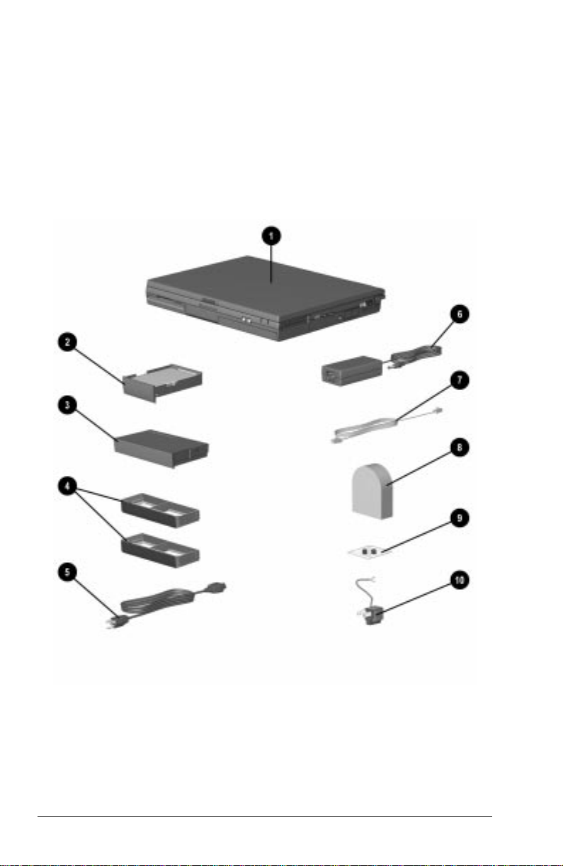
Identifying Packing Box Contents
The contents of the packing box vary according to your
geographic region and according to the computer hardware
configuration that you ordered.
The following picture and component list identify the standard
components that are included with most computer models.
As you unpack the box, make sure you have received all of the
standard and optional components that you ordered.
1-2 Getting Started
Page 29
Identifying Hardware Components
Component Function
1
Computer Compaq Armada Personal Computer.
2
Hard drive (inserted in
computer hard drive bay)
3
Battery pack (inserted in
computer battery bay)
4
Weight savers (2) ■ Protects a vacant MultiBay and
5
Power cord External adapter models: connects AC
6
AC adapter Converts AC power to DC power.
7
Modem cable (internal
modem models only)
8
Country-specific modem
adapter (provided with
internal modem models by
region as required)
9
Security screws Contains tamper-resistant security
Primary hard drive when used in hard
drive bay. Can also be used with an
adapter in the MultiBay.
Primary battery pack.
NOTE: The battery pack can be charged
and used as shipped, but battery
charge displays will not be accurate
until the battery pack is calibrated.
DualBay.
■ Can replace a MultiBay/DualBay
device to reduce computer weight.
NOTE: A weight saver can be inserted or
removed while the computer is on, off,
in Hibernation, or in Suspend.*
Adapter to AC electrical outlet.
Connects modem to RJ-11 telephone
jack or to a country-specific adapter.
Adapts modem cable for use with nonRJ-11 telephone jacks.
screws for hard drive.
:
3-to-2-prong plug adapter
(Japan only)
*In Windows 98 the term
Adapts the power cord for use with a
2-prong electrical outlet.
Standby
replaces the term
Suspend.
Getting Started 1-3
Page 30

WARNING: To reduce the risk of personal injury, electric shock, fire,
!
or damage to the equipment:
■ Do not disable the power cord grounding plug. The grounding
plug is an important safety feature.
■ Plug the equipment into a grounded (earthed) electrical outlet that
is easily accessible at all times.
■ Disconnect power from the equipment by unplugging the power
cord from the electrical outlet.
■ Do not place anything on power cords or cables. Arrange them so
that no one may accidentally step on or trip over them. Do not pull
on a cord or cable. When unplugging from the electrical outlet,
grasp the cord by the plug.
1-4 Getting Started
Page 31
chapter
2
Taking A Look AT THE
COMPUTER
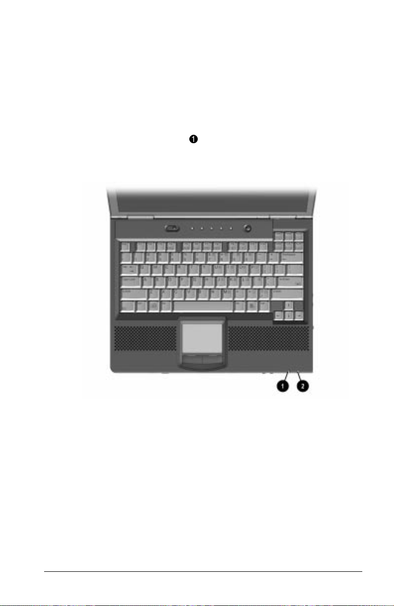
Front Components
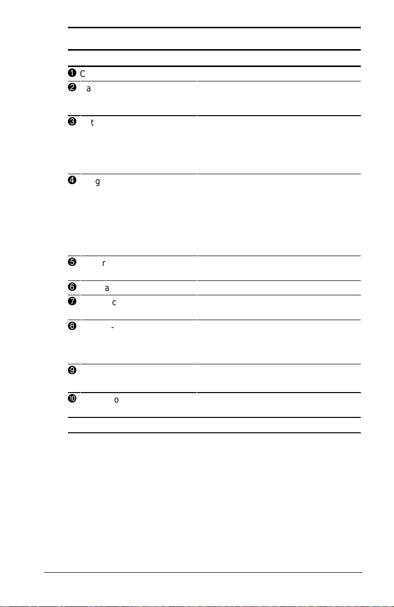
Front Components
Component Function
Power switch Slides to turn the computer on or off.
1
Standby/Suspend switch Initiates and exits Suspend. Turns on
2
While working in Windows, click
StartÅShut Down to exit the
operating system and turn off the
computer.
the computer if it is off. When used
with the Fn key on the computer, the
Suspend button initiates Hibernation.
Taking a Look at the Computer 2-1
Continued
Page 32

Front Components
Continued
Component Function
Stereo speakers Built-in speakers for high-quality
3
Battery light Indicates the battery is charging
4
Power/Suspend light Blinks every four seconds. This
5
Volume Control buttons Controls the speaker volume.
6
MultiBay Accepts a CD-ROM drive, DVD drive,
7
Speaker ports Integrated tuned loudspeaker ports
8
TouchPad Provides integrated pointing device
9
Left and right TouchPad
buttons
or
stereo sound and a multimedia
sound system.
when light is on. If the light is off, the
battery is not charging. A blinking
light indicates a low battery condition.
indicates the computer is in suspend
mode.
SuperDisk LS-120 drive, second hard
drive, third battery pack, or a weight
saver.
that allow airflow to and from the
internal stereo speakers.
functions.
Function like the left-click and right-
click buttons of an external mouse.
Used with the TouchPad, the
TouchPad button drags and
highlights.
Pointing Stick Moves the mouse cursor.
Left and right pointing
stick buttons (pointing
stick models only)
DualBay Accepts a diskette drive, a second
:
2-2 Taking a Look at the Computer
Functions like the left-click and rightclick buttons on an external mouse.
battery pack, or a weight saver.
Page 33

Left Side Components
Left Side Components
Component Function
Tilt foot Retractable feet on the rear base of
1
Battery bay Holds the primary battery pack.
2
the computer that open and lock into
place in order to angle the keyboard
to a more comfortable position.
Taking a Look at the Computer 2-3
Page 34

Right Side Components
Right Side Components
Component Function
1
PC Card slots Slots that support Type II or Type III
2
Microphone jack Connects to an external microphone.
3
Stereo speaker/
headphone jack
4
Lock provision Accepts an anti-theft cable that
5
RJ-45 jack Connects the Ethernet cable (NIC) to
6
RJ-11 jack Connects the RJ-11 modem cable to
PC Cards, such as modem, hard
drive, or network cards. These slots
accept 16-bit PC Cards and 32-bit
Cardbus Cards.
Connects to a headphone or external
speakers.
secures the computer to a fixed
object.
the computer. Available on models
with an internal NIC/modem
combination
the computer. Available on models
with an internal modem
Continued
2-4 Taking a Look at the Computer
Page 35

Right Side Components
Continued
Component Function
7
Infrared port Infrared signals for communicating
8
Composite TV-Out jack Connects a television to the
9
Tilt foot Retractable feet on the rear base of
with another computer. Links to
another IrDA-compliant device for
wireless communication.
computer.
the computer that open and lock into
place in order to angle the keyboard
to a more comfortable position.
Taking a Look at the Computer 2-5
Page 36

Rear Components
Rear Components
Component Function
Power connector Connects to an AC adapter when the
1
USB connector Allows connection to Universal Serial
2
Serial connector Connects an optional external serial
3
External monitor
4
connector
Docking connector A 176-pin expansion bus connector
5
Parallel connector Connects an optional parallel device
6
7
Keyboard/Mouse
connector
battery or charge battery are not
operating.
Bus (USB) devices, such as a
keyboard or mouse, or to a camera
for video conferencing.
device such as a mouse or printer.
Connects an optional external
display, such as an external CRT
monitor.
that connects the computer to the
optional docking solutions.
such as a printer.
Connects an external keyboard or
mouse.
2-6 Taking a Look at the Computer
Page 37

Bottom Components
Bottom Components
Component Function
Modem compartment Provides access to the internal
1
Keyboard security screw Keeps the keyboard secured to the
2
Hard drive release latch Releases the hard drive.
3
Hard drive compartment Provides access to the primary hard
4
Battery release latch Releases the primary battery pack.
5
DualBay release latch Releases the second battery pack or
6
MultiBay release latch Releases the MultiBay device from
7
modem. The modem is available on
select models and as an option for
other models.
computer.
drive. A security screw prevents
unauthorized access to the hard
drive. Use a standard screwdriver to
remove the screw.
diskette drive from the DualBay.
the MultiBay.
Taking a Look at the Computer 2-7
Page 38

Status Indicator Lights
The five lights located above the keyboard indicate system
operations and status.
Status Indicator Lights
Light Function
Hard drive/CD-ROM drive
1
light indicator
Diskette drive light
2
indicator
Num Lock On: embedded numeric keypad is
3
Caps Lock On: Caps Lock function is on.
4
Scroll Lock On: Scroll Lock key function is on.
5
Turns on when the hard drive,
optional CD-ROM drive, or optional
DVD-ROM drive is accessed.
Turns on when the diskette drive is
accessed.
active.
2-8 Taking a Look at the Computer
Page 39

chapter
3
USING THE KEYBOARD
Using the Pointing Device
The built-in Touch Pad (TouchPad models) and the EasyPoint IV
pointing stick (pointing stick models) function with any software
that supports a Microsoft-compatible mouse.
NOTE: If you are using software that does not support a Microsoft-
compatible mouse, select Advanced➔Device Options in
Computer Setup, then select the Disable Multiple Pointing
Devices check box.
Using the Keyboard 3-1
Page 40

Identifying TouchPad Components
1
TouchPad
2
Left TouchPad button
3
Right TouchPad button
3-2 Using the Keyboard
Page 41

Navigating with the TouchPad
TouchPad Procedures
Task Procedure
Move the cursor Move your finger directionally across the
Increase or decrease
cursor speed
Right-, left-, or center-click
or double-click
Highlight an item* Press down on the TouchPad as you move
Select text or an object* Position the cursor over the highlighted
Activate a selection* Position the cursor over the selection, then
Select, then drag and drop
an item*
*To perform this task exactly as you would with an external mouse, use
the left pointing-device button like the left button of an external mouse.
TouchPad surface.
Increase or decrease finger speed across
the TouchPad surface.
Press the right or left TouchPad button as
you would the corresponding button on an
external mouse.
the cursor over the item.
text or object, then quickly tap the
TouchPad once.
quickly tap the TouchPad twice.
NOTE: To select and activate a preference,
first tap the preference once to select it,
then tap the preference twice to activate it.
Press down on the TouchPad as you move
the cursor over the item, then drag the
item to the new location. To drop the item,
release the pressure.
Setting TouchPad Preferences
To access all TouchPad features and settings, including mouse
trails, cursor speed, double-click space, and Windows 98 singleclick mode, select StartÅSettingsÅControl PanelÅMouse.
Using the Keyboard 3-3
Page 42

Identifying Pointing-Stick Components
1
EasyPoint IV pointing stick
2
Left pointing-stick button
3
Right pointing-stick button
4
Scroll pointing-stick
button
3-4 Using the Keyboard
Page 43

Navigating with the Pointing-Stick
Pointing-Stick Procedures
Task Procedure
Move the cursor Directionally press the pointing stick.
Increase or decrease
cursor speed
Right-, left-, or center-click
or double-click
Highlight an item* Press and hold down the pointing stick as
Select text or an object* Position the cursor over the highlighted
Activate a selection* Position the cursor over the selection, then
Select, then drag and drop
an item*
*To perform this task exactly as you would with an external mouse, use
the left pointing-device button like the left button of an external mouse.
Increase or decrease pressure on the
pointing stick.
Press the right, left, or scroll pointing stick
buttons as you would the right, left, or
center buttons on an external mouse.
you move the mouse cursor over the item.
text or object, then quickly tap the pointing
stick once.
quickly tap the pointing stick twice.
NOTE: To select and activate a preference,
first tap the preference once to select it,
then tap the preference twice to activate it.
Press down on the pointing stick as you
move the cursor over the item, then drag
the item to the new location. To drop the
item, release the pressure.
Using the Keyboard 3-5
Page 44

Setting Pointing-Stick Preferences
EasyPoint IV pointing stick model
■ To access settings common to any Microsoft-compatible
mouse, such as mouse trails, cursor speed, double-click
pace, and Windows 98 single-click mode, select
StartÅSettingsÅControl PanelÅMouse.
■ To access settings and instructions for using additional
EasyPoint IV pointing stick features, such as scrolling,
magnifying, and selecting an icon without tapping the
pointing stick, select StartÅSettingsÅControl
PanelÅTrackpoint.
3-6 Using the Keyboard
Page 45

Using Hotkeys
Hotkeys are preset combinations of the Fn key 1 plus a second
key that activate frequently used system functions. The icons on
the function keys
F4-F10 2, Fn+T
functions.
■ To use hotkeys on an external keyboard, which does not have
Fn key, press the Scroll Lock key twice, then the second key
an
only of the hotkeys combination. For example, to use the
Fn+F10 hotkeys, press Scroll LockÅScroll Lock+F10.
The Fn+F6 hotkeys cannot be used on an external
NOTE:
keyboard connected through a USB connector.
■ To close a window opened with hotkeys, use standard
Windows procedures or press the hotkeys.
3
, and Fn+Esc 4 represent these
Hotkeys Quick Reference
Task Hotkeys
Switch the image Fn+F4
Adjust system volume Fn+F5
Using the Keyboard 3-7
Continued
Page 46

Hotkeys Quick Reference
Continued
Task Hotkeys
Initiate Quick Controls Fn+F6
Set a power conservation level Fn+F7
View battery status Fn+F8
Adjust panel contrast FN+F9
Adjust screen brightness Fn+F10
Display system information Fn+Esc
Stretch text Fn+T
Switching the Image
In Windows 95 or Windows NT 4.0 toggle Fn+F4 to switch the
image among the computer display, an external display, and
simultaneous display. The external display can be connected
through the external monitor connector or the video-out jack.
Windows 98 toggle
computer display and an external display that is connected to the
external monitor connector.
■ When MultiMonitor is enabled, press Fn+F4 to turn off the
external display and disable MultiMonitor.
■ When MultiMonitor is disabled, toggle Fn+F4 to switch the
image among the computer display, the external display, and
simultaneous display.
Fn+F4 to switch the image between the
Adjusting System Volume
■ To adjust system volume:
❏ Press Fn+F5 using the on-screen slide button or the
keyboard arrow keys.
or
❏ Press the front-mounted volume control buttons. See Front
Components in Chapter 2.
■ To mute or restore volume:
❏ Press Fn+F5+M
or
❏ Press Fn+F5, then select or clear the Mute check box.
3-8 Using the Keyboard
Page 47

Initiating Quick Controls
Quick Controls are security features that can disable the keyboard
and pointing device and clear the screen. Before you can use
Quick Controls, set a power-on password and enable Quick
Control preferences. For instructions, refer to Chapter 13.
■ To initiate Quick Controls, press Fn+F6.
■ To exit Quick Controls, enter your power-on password.
The
Fn+F6 hotkeys cannot be used on an external keyboard
connected through a USB connector on the computer or an
optional docking base.
Setting a Power Conservation Level
In Windows 98 press Fn+F7 to open the Power Schemes window.
In Windows 95 or Windows NT 4.0 press
Fn+F7 to open the
Battery Conservation Settings window. Select one of the
following preset battery conservation levels:
■ High—Maximizes running time from a single charge.
■ Medium—Balances system performance with running time.
■ None (Drain)—Runs the computer at full power.
Viewing Battery Status
Press Fn+F8 to view the status of all installed batteries. Battery
packs are listed by location.
■ To display the location of a listed battery, select the
corresponding battery icon.
■ A lightening bolt icon beside a battery icon indicates that the
battery pack in that location is charging.
Adjusting Panel Contrast
Press Fn+F9 to adjust the panel contrast of the computer screen
with an on-screen slide button or with the arrow keys. This
feature is only available to select models.
Using the Keyboard 3-9
Page 48

Brightness
Press Fn+F10 to adjust the brightness of the computer screen
with an on-screen slide button or with the arrow keys.
Displaying System Information
Press Fn+Esc to display information about system hardware
components and software version numbers.
NOTE: The number beside System BIOS is the version number of
your system ROM.
Stretching Text
When the computer is running MS-DOS under Windows and the
desktop area resolution is set lower than the display resolution,
Fn+T to toggle the image between Text Stretch, which
press
stretches the text to fill more of the screen, and not stretched.
Text Stretch is the default.
3-10 Using the Keyboard
Page 49

Using the Embedded Numeric Keypad
Toggling the Keypad On and Off
n
To convert the embedded numeric keypad section 1 of the
computer keyboard to a numeric keypad, press
❏ When the embedded numeric keypad is enabled, the
characters upper-right on the keypad keys are active and
the num lock light is on.
❏ To disable the embedded numeric keypad, toggle
Fn+Num Lk.
■ The embedded numeric keypad cannot be enabled while
an optional external keyboard or numeric keypad is connected
to the computer.
Fn+Num Lk 2.
Using the Keyboard 3-11
Page 50

Operating the Keypad Keys as Standard Keys
To use the embedded numeric keypad keys as standard keyboard
keys while the keypad is enabled:
■ Press and hold Fn to use the keys as you would when typing in
lowercase.
■ Press and hold Fn+Shift to use the keys as you would when
typing in uppercase.
Enabling the Keypad at Startup
■ To set the computer to start up with the embedded
numeric keypad enabled—
1. Turn on or restart the computer, then press
F10 when the
blinking cursor appears upper-right on the screen.
❏ To change the language, press F2.
❏ For navigation instructions, press F1.
2. Select AdvancedÅDevice Options, then press Enter.
3. Toggle the field beside Num Lock State at Boot to On, then
F10.
press
4. To save your preferences, then close Computer Setup and
restart the computer, select FileÅSave Changes and Exit,
then press
Enter.
5. When you are prompted to confirm your action, press F10.
■ To disable the embedded numeric keypad at startup—
Repeat the above procedure with the Num Lock State at Boot
field toggled Off.
NOTE: The embedded numeric keypad can be enabled or disabled
Fn+Num Lk in either startup state.
with
3-12 Using the Keyboard
Page 51

chapter
4
USING BATTERY PACKS
Learning About Battery Packs
The computer accommodates up to three rechargeable battery
packs at one time. Battery packs are supported in the:
■ Battery bay in the computer (primary battery pack)
■ DualBay in the computer (secondary battery pack)
■ MultiBay in the computer (third battery pack)
With the computer turned off, each battery pack will recharge in
less than three hours. With the computer turned on, each battery
pack will recharge in less than five hours.
If two fully charged battery packs are installed, one can be
removed while the computer is on without affecting system
operation. With only one battery pack installed, turn off the
computer or initiate Hibernation before removing a battery, or
connect to external AC power before removing the battery pack.
For more information on using Hibernation, see Chapter 5.
Before removing a battery pack when the computer is in suspend,
ensure that the computer is connected to a fully charged battery
pack or AC power source. For more information on using
Suspend, see Chapter 5.
WARNING: Your computer contains a lithium-ion battery pack.
!
There is a risk of fire and burns if the battery pack is not handled
properly. Do not disassemble, crush, puncture, short external
contacts, or dispose of in fire or water. Do not expose to
temperatures higher than 60°C. Replace only with the Compaq
spare designated for this product.
Using Battery Packs 4-1
Page 52

WARNING: Batteries/battery packs and accumulators should not be
!
disposed of with general household waste. In order to forward them
to recycling or proper disposal, please use the public collection
system or return them to Compaq, your authorized Compaq Partners,
or other agents.
Using a New Battery Pack
Charge the battery pack in the computer’s battery bay, a DualBay,
or a MultiBay while connected to an external power source or
while docked in the optional convenience base.
You can also charge up to two battery packs in the optional
battery charger. However the battery charger has only one slot for
the main battery and one slot for the MultiBay battery. Therefore,
you can only charge two battery packs at one time if one is the
main battery and the other battery is for the MultiBay.
IMPORTANT: A new battery pack should be fully charged before it
is used for the first time. The battery pack will work without
being fully charged, but the battery gauge will not show an
accurate charge until the battery pack receives its first full charge.
Charging Battery Packs
Battery packs charge in the following sequence:
1. The primary battery in the computer battery bay
2. A second battery pack in the computer DualBay
3. A third battery pack in the computer MultiBay
Battery packs are discharged in the reverse order, with the battery
pack in the MultiBay depleted first. See Chapter 2 for bay
locations.
To charge battery packs, follow these steps:
1. With battery packs in the battery bay, DualBay, and/or
MultiBay, connect the power cord to the computer and plug it
into an electrical outlet.
2. Turn on the computer if you want to use it while the battery
packs are charging.
4-2 Using Battery Packs
Page 53
NOTE: The battery charge light is the right light on the front edge
of the computer. It turns on (solid) when a battery pack (in the
battery bay, DualBay, or MultiBay) is charging. It turns off when
fully charged. It blinks in a low-battery condition.
When the battery charge light turns off, the battery packs are fully
charged.
Inserting and Removing the Primary Battery
Pack
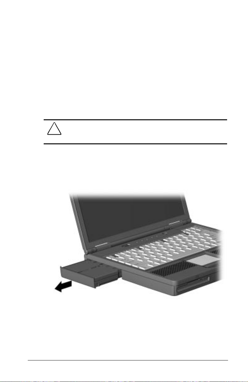
Removing the Primary Battery Pack
CAUTION: If the battery pack you are about to remove is the only
source of power to the computer, initiate Hibernation or connect the
computer to external power before removing the battery.
1. Pull forward on the primary battery release latch to release the
battery pack.
2. Remove the battery pack from the primary battery bay.
Using Battery Packs 4-3
Page 54

Inserting the Primary Battery Pack
CAUTION: If the battery pack you are about to remove is the only
source of power to the computer, initiate Hibernation or connect the
computer to external power before removing the battery.
Insert a battery pack into the battery bay with the large label on
the battery pack facing up and the battery contacts facing in. Push
the battery pack into the battery bay until it is firmly seated.
NOTE: See Chapter 6 to insert and remove battery packs to and
from the DualBay and MultiBay.
4-4 Using Battery Packs
Page 55

Storing a Battery Pack
CAUTION: To prevent damage to a battery pack, do not expose it to
high temperatures for extended periods of time.
If the computer will be unused and unplugged from an external
power source for more than two weeks, remove and store the
battery packs.
Proper storage procedures reduce the self-discharge rate of a
battery pack. Store a battery pack in a cool, dry place within the
following temperature ranges.
Recommended Battery Pack Storage Temperatures
Storage Time Temperature Range °F Temperature Range °C
Less than
1 month
No more than
3 months
Unlimited 32°– 86° 0°–30°
32°–122° 0°–50°
32°–104° 0°–40°
Maximizing Battery Pack Life
Battery pack operating time varies depending on the system
components, options, and applications used. Battery operating
time can increase by as much as 50 percent by controlling the
energy used by the computer and the energy stored in the battery
pack.
NOTE: The display, processor, and drive components use the
majority of battery power.
To maximize battery pack life, use the following guidelines:
■ Select the High level of power management (not available
under Windows 98). See Chapter 5 for more information on
power management.
■ Initiate Suspend or Hibernation or turn the computer off when
you are not using it.
■ Reduce the display brightness and select a shorter screen save
timeout.
■ Keep a battery pack in the computer when you are using the
computer with external power.
Using Battery Packs 4-5
Page 56

■ Disconnect external equipment that does not have its own
power source. (External equipment connected to the computer
drains the battery pack.)
■ Exit modem programs when you are not using them.
■ Remove a PC Card when you are not using it.
■ When storing the computer for more than two weeks, remove
battery packs and store them separately to reduce the
discharge rate and increase battery life.
■ Store the battery pack in a cool, dry place when it is not in
use. High temperatures cause a battery pack to lose its charge
more quickly and reduce battery pack life. For more
information on storing battery packs, see "Storing a Battery
Pack" in this chapter.
■ Format diskettes while using external power when possible.
(Formatting diskettes increases the drain on a battery pack.)
Recycling Used Battery Packs
To find out if the battery pack recycling program is available in
your area, check the “Worldwide Telephone Numbers” in
Appendix A. If a number for recycling is not listed for your area,
contact your Compaq authorized dealer, reseller, or service
provider.
System Beeps
Beeps with a Blinking Battery Charge Light
When the computer beeps while the battery charge light is
blinking, the computer has entered a low battery condition.
CAUTION: When you are alerted of a low battery condition, very
little battery charge remains. Save your information and take
immediate action to resolve the low battery condition.
See “Turning Beeps On or Off” in this chapter to avoid being
alerted with system beeps.
4-6 Using Battery Packs
Page 57

Beeps with a Blinking Power/Suspend Light
When the computer beeps while the Power/Suspend light is
blinking, the computer has initiated Suspend. See Chapter 5 for
more information on using Suspend.
NOTE: When the computer is in Suspend and a low battery
condition occurs, you cannot press the power button or suspend
button to exit Suspend. Connect the computer to AC power until a
fully charged battery is available.
See the following section, “Turning Beeps On or Off,” to avoid
being alerted with system beeps.
Turning Beeps On or Off
Based on the type of beeps to be turned on or off, do one of the
following:
■ To enable or disable PC Card beeps, click Control PanelÅ
double-click PC Card iconÅGlobal Settings tab, then click
the Disable PC Card Sound Effects box.
■ To disable only low battery warning beeps, click StartÅ
SettingsÅControl PanelÅdouble-click PowerÅPower
PropertiesÅConservation Settings tab. Then click the
Warning Beeps Off button.
NOTE: Application-specific beeps must be controlled through the
application software.
Using Battery Packs 4-7
Page 58

chapter
5
MANAGING POWER
Selecting a Power Source
Task Recommended Power Source
Work within installed
software applications
Charge a battery pack
inserted in the computer
Calibrate a battery pack External power supplied through
Modify system software External power supplied through
■ Charged battery pack inserted into
the computer
or
■ External power supplied through
❏ AC adapter
❏ Optional docking base
❏ Optional Automobile Power
Adapter/Charger
❏ Optional Aircraft Power Adapter
External power supplied through
■ AC adapter
■ Optional docking base
■ Optional Automobile Power
Adapter/Charger
■ Power cord or AC adapter
■ Optional docking base
AC adapter
NOTE: If your external monitor is not Energy Star compliant,
enabling monitor energy-saving features may cause video
distortion when the screen save timeout occurs.
Managing Power 5-1
Page 59

Using Suspend (Standby) and Hibernation
You will use the power switch 1, Suspend button 2, Fn key 3,
and the power/suspend light 4 as you turn the computer on or off
or place it in Suspend (Standby) or Hibernation.
■ Suspend, called Standby in Windows 98, is an energy-saving
feature that reduces power to system components that are not
being used. When the computer is in Suspend (Standby), your
work is saved in random access memory (RAM) and the
screen is cleared.
■ Hibernation is an energy-saving feature that saves all
information in RAM to a hibernation file on the hard drive,
then shuts down the computer.
If you are leaving your work, consider:
If you plan to resume shortly—Initiating Suspend (Standby)
clears the screen, uses less power than leaving the computer on,
and your work returns instantly to the screen when you press the
suspend button. A fully charged battery pack can support Suspend
(Standby) for up to a week, unless frequent charging and
discharging has shortened battery pack life.
5-2 Managing Power
Page 60

If the computer will be disconnected from external power for
more than two weeks—To extend the useful life of the battery
pack, shut down the computer, then remove the battery pack and
store it in a cool, dry place.
If you plan to resume within two weeks—Initiating Hibernation
clears the screen, saves your work to the hard drive, and uses less
power than Suspend (Standby). Returning to work saved in
Hibernation takes a little longer than returning to work placed in
Suspend (Standby), but is much faster than returning to your
place manually after restarting the computer. A fully charged
battery pack supports Hibernation indefinitely.
Using Standby (Suspend) and Hibernation
Task Procedure Result
Turn the
computer
on from
shutdown
Shut down
the
computer
Initiate
Suspend*
*In Windows 98 the term
**In Windows 98 the term
suspend button.
Slide power switch. Power/suspend* light turns on.
Operating system loads.
Shut down the
computer.
■ Press suspend
button.**
or
■ Select Stand by
(Windows 98 only)
on the shutdown
menu.
Standby
sleep button
Power/suspend* light turns off.
Operating system closes and
turns off all power.
Computer turns off.
Power/suspend* light blinks.
System beeps twice.
Screen clears.
replaces the term
replaces the term
Suspend.
Continued
Managing Power 5-3
Page 61

Using Standby (Suspend) and Hibernation
Continued
Task Procedure Result
Exit
Suspend*
Initiate
Hibernation
Restore
from
Hibernation
*In Windows 98 the term
**In Windows 98 the term
■ Press suspend
button.**
or
■ Slide power switch.
Press Fn + suspend
button.
Slide power switch. Power/suspend* light turns on.
suspend button.
Standby
sleep button
Power/suspend* light turns on.
System beeps once.
Your work returns to the screen.
Power/suspend* light turns off.
System beeps twice.
Screen clears.
System beeps once.
Your work returns to the screen.
replaces the term
replaces the term
Suspend.
Managing Low-Battery Conditions
Identifying Low-Battery Conditions
■ When a battery pack that is the only source of power available
to the computer reaches a low-battery condition
❏ The system beeps five times.
❏ The battery light
2
blinks.
5-4 Managing Power
Page 62
■ If the low-battery condition is not resolved, the computer will
enter a critical low-battery condition. In a critical low-battery
condition,
❏ If Hibernation is enabled and the computer is on or in
Suspend (Standby)—The computer beeps twice, then
initiates Hibernation. Hibernation is enabled by default.
❏ If Hibernation is disabled and the computer is on or in
Suspend (Standby)—The computer beeps twice, and the
power/suspend light 1 blinks. The computer remains
briefly in Suspend (Standby), then shuts down and your
unsaved work is lost.
Managing Power 5-5
Page 63

Resolving Low-Battery Conditions
■ If external power is available, do one of the following—
❏ Connect the computer to an electrical outlet with the AC
adapter.
❏ Dock the computer in a docking base that is connected to
external power.
❏ Plug an optional Automobile Power Adapter/Charger into
the power connector on the computer and into a vehicle
cigarette lighter receptacle.
❏ Plug an optional Aircraft Power Adapter into the power
connector on the computer and into the in-seat power
supply available on some commercial aircraft.
NOTE: An optional Aircraft Power Adapter can be used to run
the computer, but cannot be used to charge a battery pack.
■ If a charged battery pack is available—Save your files and
press the suspend button to initiate Suspend (Standby), then
remove the discharged battery pack and insert a charged
battery pack.
■ If neither external power nor a charged battery pack is
available—
❏ Press Fn + the suspend button to initiate Hibernation
or
❏ Save your work, then shut down the computer.
Restoring from Hibernation After Resolving
a Critical Low-Battery Condition
Slide the power switch. If the computer does not have
enough power to restore your work:
1. Press
2. Insert a charged battery pack or connect the computer to
3. Slide the power switch.
5-6 Managing Power
Ctrl+Alt+Del to abort the restoration.
external power.
Page 64

Charging a Battery Pack
A battery pack can be recharged wherever external power is
available. These locations include the computer battery bay,
DualBay, MultiBay, an optional Battery Charger, and the docking
base.
NOTE: Charging may be delayed if a battery pack is new, has not
been used for 2 weeks or more, or is much warmer or cooler than
a comfortable room temperature.
■ If you are charging the battery pack in the computer—
❏ External power can be supplied to the computer through
the AC adapter, an optional docking base, or an optional
Automobile Power Adapter/Charger.
NOTE: An optional Aircraft Power Adapter cannot be used
to charge a battery pack.
❏ The battery light, shown below, turns on while the battery
pack is charging and turns off when the battery pack is
fully charged.
Managing Power 5-7
Page 65

■ To increase the accuracy of all battery charge displays—
❏ Allow a battery pack to discharge to the low-battery level
through normal use before charging it.
❏ When you charge a battery pack, charge it fully.
❏ Before charging a new battery pack or a battery pack that
has not been used for two weeks or more, calibrate the new
battery pack or check the calibration on the unused
battery pack.
Monitoring the Charge in a Battery Pack
NOTE: The references in Windows 98 battery charge displays to a
“standard APM battery pack” apply to all battery packs that can
be used in the computer.
Using the Battery Status Tab
To access the Battery Status tab, press the Fn+F8 hotkeys or select
StartÅSettingsÅControl PanelÅpower icon (named Power,
Power Management, or Compaq Power, depending on your
operating system)ÅBattery Status tab.
■ To display the location of a listed battery, select the
corresponding battery icon.
■ A lightening bolt icon beside a battery icon indicates that the
battery pack in that location is charging.
Using the Battery Meter or Power Meter Icon
The battery meter icon, called the power meter icon in
Windows 98, changes shape to indicate whether the computer is
running on external power or on a full, half-full, or nearly
discharged battery pack.
To display the battery meter icon in the taskbar
■ In Windows 95 select StartÅSettingsÅControl
PanelÅPowerÅPower tab, then select the Show Battery
Meter on the Taskbar check box.
■ In Windows 98 select StartÅ SettingsÅControl
PanelÅPower ManagementÅPower Meter tab, then select
the Show Power Meter on the Taskbar check box.
■ In Windows NT 4.0 the battery meter icon displays in the
taskbar by default.
5-8 Managing Power
Page 66

When the battery meter or power meter icon is displayed in the
taskbar, the icon can also be used as follows.
In Windows 95 and Windows 98—
Task Procedure
View the total battery power
remaining in the system.
Enable/disable an on-screen
critical low-battery warning.
Access the Power tab in the
Power Properties window.
Open battery meter in a
popup window.
Display charge information as
a percent of a full charge or
as the run time remaining.
Rest the cursor over the icon.
Left-click the icon, select or clear
the Enable Low Battery Warning
check box, then select OK.
Right-click the icon, select Adjust
Power Properties, then press Enter.
Double-click the icon.
Left-click the icon, then select your
preference in the popup window.
In Windows NT 4.0—
Task Procedure
View the total battery power
remaining in the system.
Open the Compaq Power
Properties window.
Rest the cursor over the icon.
Double-click or right-click the icon.
Using the Power or Power Meter Tab
The Power tab, called the Power Meter tab in Windows 98, is
available in Windows 95 and Windows 98.
■ To access the tab
❏ In Windows 95 select StartÅSettingsÅControl
PanelÅPowerÅPower tab.
❏ In Windows 98 select StartÅSettingsÅControl
PanelÅPower ManagementÅPower Meter tab.
■ To view the combined percent of total power remaining in all
battery packs in the system, clear the Show the Status of All
Batteries check box.
Managing Power 5-9
Page 67

■ To view the percent of total power remaining in each battery
pack in the system, select the Show the Status of All Batteries
check box. The three numbered icons correspond as follows
to battery pack locations.
1 Computer battery bay
2 Computer DualBay
3 Computer MultiBay
Calibrating a Battery Pack
Calibration increases the accuracy of all battery charge displays.
The calibration utility supports all battery packs that can be used
in the computer.
Use the calibration utility both to check the calibration of a
battery pack and to calibrate or recalibrate a battery pack.
■ A battery pack cannot be calibrated unless the utility reports
that it needs calibration.
❏ A new battery pack can be charged, then used to run the
computer before the battery pack is calibrated. However,
the amount of charge in the new battery pack cannot be
reported accurately until the new battery pack has been
calibrated.
❏ Check the calibration of a used battery pack periodically
and whenever battery charge displays seem inaccurate.
■ While a battery pack is being calibrated, it is fully charged,
then fully discharged.
❏ A battery calibration icon in the taskbar displays an Up
arrow during the charge phase and a Down arrow during
the discharge phase.
❏ A calibration cannot resume if the calibration is stopped or
if the computer is shut down during a calibration. An
interrupted calibration must be restarted.
❏ After calibration, a battery pack must be charged before it
can be used to run the computer.
5-10 Managing Power
Page 68

■ The calibration utility calibrates one battery pack at a time
and can run in the background as you use the computer
or overnight.
CAUTION: To prevent loss of work, ensure that the computer
remains connected to AC power throughout a calibration.
Running a Calibration
1. If you are checking the calibration of a battery
pack—Insert the battery pack into the computer battery
bay, a DualBay, or a MultiBay.
If you are calibrating a battery pack—Insert the battery
pack into the computer battery bay, a DualBay, or a MultiBay.
Then connect the computer to external power with the AC
adapter or dock the computer in a docking base that is
connected to external power.
2. Access the Battery Calibration tab.
■ In Windows 95 select StartÅSettingsÅControl
PanelÅPowerÅBattery Calibration tab.
■ In Windows 98 select StartÅSettingsÅControl
PanelÅPower ManagementÅBattery Calibration tab.
■ In Windows NT 4.0 select StartÅSettingsÅControl
PanelÅCompaq PowerÅBattery Calibration tab.
3. View the calibration reports in the Status column. The battery
numbers in the Battery column correspond to the following
locations:
Battery Number Battery Pack Location
1 Computer battery bay
2 Computer DualBay
3 Computer MultiBay
4. Select any location number with “Needs calibration” beside it
in the Status column.
5. Select the Start Calibration button.
Managing Power 5-11
Page 69

Stopping a Calibration
Shut down the computer or select the Stop Calibration button on
the Battery Calibration tab. The Stop Calibration button is visible
only during a calibration.
Using Power Preferences
You can increase, decrease, and allocate the power used by the
computer by setting power preferences.
■ Increasing power increases performance, while decreasing
power conserves energy and extends the running time from a
battery pack.
■ By decreasing power to unused components and functions,
you can allocate more power to the components and functions
that you are using.
Many power preferences consist of timeout settings.
■ A timeout is the period of inactivity before the system
initiates a power change or reduces power to a component.
For example, the computer is preset to initiate Suspend
(Standby) after a period of inactivity. The time interval
between when you stop using the computer and when the
computer initiates Suspend (Standby) is a Suspend (Standby)
timeout.
■ Depending on your operating system, you can set timeouts
that are specific to various conditions, components, or
procedures as well as specify the duration of those timeouts.
The following tables list power preference procedures that are not
described in your operating system documentation.
■ For additional power preference options, refer to your
operating system documentation.
■ For a summary of battery conservation settings that extend the
running time from a single charge, refer to “Conserving
Battery Power” later in this chapter.
5-12 Managing Power
Page 70

Setting Power Preferences
in Windows 95 and Windows NT 4.0
Refer to the following table for procedures on setting power
preferences.
Preference Procedure from Control Panel
Select a preset level of power
use that applies whenever the
computer is running on a
battery pack.
NOTE: A battery conservation
level can also be displayed and
selected with the Fn+F7 hotkeys.
Create a level of power use that
applies settings for the following
whenever the computer is
running on a battery pack
■ Suspend timeout
■ System idle timeout
■ Processor speed
■ Screen brightness
Enable/disable low-battery
warning beeps.
Set Hibernation timeout. Select Power (or Compaq Power)Å
Exit Suspend after a userselected timeout.
Select Power (or Compaq Power)Å
Battery Conservation Settings tab,
then select a conservation level:
■ High provides maximum battery
conservation.
■ Medium balances battery
conservation and system
performance.
■ None (drain) provides maximum
power.
Select Power (or Compaq Power)Å
Battery Conservation Settings tab.
Select Custom, then enter your
preferences.
NOTE: Although a battery conservation
level can be displayed and selected
with the Fn+F7 hotkeys, Custom level
preferences must be entered on the
Battery Conservation Settings tab.
Select Power (or Compaq Power)Å
Battery Conservation Settings tab,
then select the On or Off radio
button.
Hibernation tab, then select a timeout
from the Timeout drop-down list.
NOTE: This setting does not affect
system-initiated Hibernation during a
critical low-battery condition.
Select Power (or Compaq Power)Å
Resume Timer tab. Select the
Enabled check box, then select a
date from the Date drop-down list
and a time from the Time drop-down
list.
Continued
Managing Power 5-13
Page 71

Preference Procedure from Control Panel
Set computer to initiate
Hibernation rather than
Suspend.
In Windows 95, turn off power
to an optional PC Card modem
Change location of Hibernation
file.
Enable/Disable Hibernation. Select Power (or Compaq Power)Å
In Windows NT 4.0, create a
general level of power use that
applies whenever the computer
is running on external AC or DC
power. You can enter settings
for
■ Screen save timeout.
■ Hard drive timeout.
■ Energy-saving monitor
timeout.
Select Power (or Compaq Power)Å
Hibernation tab, then select Standby
in the Timeout drop-down list.
Select Power (or Compaq Power)Å
PC-Card Modems tab, then select
Turn Off Power to PC Card Modem
when not in use check box.
Select Power (or Compaq Power)Å
Hibernation tab, then select the new
location from the Drive for Hibernation
File drop-down list.
Hibernation tab, then select the On or
Off button.
CAUTION: If the computer reaches a
critical low-battery condition while
Hibernation is turned off, unsaved
work can be lost.
1. Select Compaq
PowerÅAC Energy Saver tab.
2. Select the AC Energy Saver On
radio button.
3. To set a screen save timeout,
select a timeout in the Screen
Save drop-down list.
4. To set a hard drive timeout, select
a timeout in the Hard Disk Idle
drop-down list.
5. To enable an external monitor to
enter a low-power mode following
a screen save timeout, select the
Energy Save Monitor check box.
NOTE: You will not be logged off a
network when the monitor enters
low-power mode.
5-14 Managing Power
Page 72

Setting Power Preferences in Windows 98
To access most power preference settings—Select
StartÅSettingsÅControl PanelÅPower Management. For
information about setting all Power Management preferences
except the following, refer to your Windows 98 documentation.
To enable or disable Hibernation—Select the Hibernation tab,
then select the On or Off button.
To set a screen brightness level that applies when the
computer is running on a battery pack—Select the Battery
Conservation Settings tab, then select a percent from the
Brightness drop-down list.
If you are accustomed to running Windows 95 or
Windows NT 4.0 on a Compaq portable computer—You will
find most of the power preference options you formerly accessed
in Power Properties window in the Windows 98 Power
Management Properties window. However, in Windows 98
■ Processor speed is managed by the operating system.
■ The easiest way to turn off power to a PC Card is to remove
the PC Card.
■ The Fn+F7 hotkeys open the Power Schemes window.
■ The preferences you formerly set on the Resume Timer tab
can be set at StartÅProgramsÅAccessoriesÅSystem
ToolsÅScheduled Tasks.
Managing Power 5-15
Page 73

Turning Auto Insert Notification On or Off
Auto Insert Notification runs a CD-ROM or DVD-ROM on
insertion, but drains power and prevents system-initiated Suspend
(Standby) and prevents system-initiated hibernation.
NOTE: The Auto Insert Notification prevents system-initiated
(timeout) suspend/hibernation in Windows 95 and
Windows NT 4.0.
To turn off Auto Insert Notification:
■ In Windows 95 or Windows 98 select StartÅSettingsÅ
Control PanelÅSystemÅDevice ManagerÅCD-ROMÅ
Properties. Clear the CD-ROM Auto Insert Notification
check box.
■ In Windows NT 4.0 select StartÅSettingsÅControl
PanelÅCompaq PowerÅBattery Conservation Settings tab.
Clear the CD-ROM Auto Insert Notification check box.
To turn on auto insert notification, access the CD-ROM Auto
Insert Notification check box as instructed above, then select the
check box.
Conserving Battery Power
Battery Power Conservation Checklist
■ Exit modem applications and turn off local area network
(LAN) connections when you are not using them.
■ Disconnect external equipment you are not using that is not
connected to an external power source.
■ If you leave your work, initiate Suspend (Standby) or
Hibernation or shut down the computer.
■ Remove PC Cards you are not using.
■ Use the Fn+F10 hotkeys to quickly raise and lower display
brightness as you work.
■ Run the computer on external power while formatting
a diskette.
5-16 Managing Power
Page 74

Conserving Battery Power in Windows 95
■ Select StartÅSettingsÅControl PanelÅPower. Then:
❏ On the Battery Conservation Settings tab, select the High
battery conservation level or select the Custom battery
conservation level, then enter even lower settings.
❏ On the Disk Drives tab, set a low When Powered By
Batteries timeout for the disk drive.
❏ If you are using a PC Card modem, click the PC-Card
Modems tab, then select the Turn Off PC-Card Modems
When Not in Use check box.
■ If Infrared Monitor is enabled, select
StartÅSettingsÅControl PanelÅInfraredÅOptions tab, then
clear the Search for and Provide Status for Devices in range
check box.
IMPORTANT: You cannot establish an infrared link while this
check box is cleared. For more information about infrared,
refer to Chapter 8.
■ If a CD-ROM or DVD-ROM is in the system, clear the CD-
ROM Auto Insert Notification check box.
Conserving Battery Power in Windows 98
■ Select StartÅSettingsÅControl PanelÅPower
ManagementÅPower Schemes tab, then create a power
scheme that conserves battery power.
■ Select StartÅSettingsÅControl PanelÅPower
ManagementÅBattery Conservation Settings. Then select a
low screen brightness.
■ Select the infrared icon in the task barÅOptions tab, then
clear the Search for and Provide Status for Devices in range
check box.
IMPORTANT: You cannot establish an infrared link while this
check box is cleared. For more information about infrared,
refer to Chapter 8.
Managing Power 5-17
Page 75

Conserving Battery Power in Windows NT 4.0
■ Select the Start buttonÅSettingsÅControl PanelÅCompaq
PowerÅBattery Conservation Settings tab. Then:
❏ Select the High battery conservation level
or
❏ Select the Custom battery conservation level, then enter
even lower settings.
5-18 Managing Power
Page 76

chapter
6
WORKING WITH REMOVABLE
DRIVES AND DEVICE BAYS
Bay Configuration
The three computer bays support standard as well as optional
devices. Some devices can be hot plugged, while others must be
inserted after the computer has been turned off. The following
table is a list of devices supported in all bays, as well as the
computer power state required before inserting the device (see
Chapter 2 for bay locations):
Bay Configuration
Functional Bay Devices Supported Power State
MultiBay CD-ROM drive Off
DVD drive Off
LS-120 Drive Off
Second hard drive Off
Diskette Drive On
Third battery pack On
DualBay Diskette drive On
Second battery pack On
Battery bay Primary battery pack On
NOTE: If two 3.5-inch/8.89-cm diskette drives are inserted in the
MultiBay and the DualBay at the same time, only the DualBay
diskette drive will work.
Working with Removable Drives and Device Bays 6-1
Page 77

Caring for Removable Drives
Removable drives such as the hard drive, CD-ROM or DVDROM drive, diskette drive, and LS-120 drive are fragile computer
components that must be handled with care.
WARNING: To reduce the risk of personal injury from hot surfaces,
!
allow the internal system components to cool before touching them.
CAUTION: To prevent damage to the computer or removable drive
or to prevent loss of information, observe the following precautions.
■ Back up the information on a hard drive before removing it.
Failure to back up the hard drive can result in loss of
information if the drive is handled improperly.
■ If there is a diskette, compact disc, or digital video disc in a
drive, remove it prior to removing the media from the
computer.
■ Do not remove a CD-ROM or DVD-ROM drive with the tray
extended. Before removing the drive, push the drive tray into
the drive.
■ Ensure that you are discharged of static electricity before
handling a removable drive. Electrostatic discharge can
damage electronic components. When handling a removable
drive, always grasp the outer case and avoid touching the
connectors.
■ Do not use force when inserting a drive into a bay. Excessive
force may damage the connectors.
■ Carefully handle the removable drive. DO NOT DROP IT.
■ Avoid exposing a hard drive to products with magnetic fields
such as video and audio tape erasure products, monitors, and
speakers.
■ Do not spray the drive with cleaners or expose it to liquids.
■ Avoid exposing the drive to temperature extremes.
6-2 Working with Removable Drives and Device Bays
Page 78

Changing the Startup Sequence with MultiBoot
If more than one drive is in the system, the computer selects the
drive to start from by searching for (1) a bootable CD-ROM or
DVD-ROM; (2) a bootable diskette; and (3) a bootable hard
drive. The computer can start from:
■ A bootable hard drive in the computer or diskette drive.
■ Any bootable diskette or hard drive in an optional docking
base.
■ Any bootable CD-ROM or DVD-ROM.
NOTE: A bootable hard drive, CD-ROM, DVD-ROM, or diskette
contains files needed by the computer to start up and operate
properly.
By default, MultiBoot is disabled and the computer selects the
startup drive by searching these locations in this sequence:
1. Diskette drive
2. Computer hard drive
3. Computer MultiBay
To enable MultiBoot and change the sequence of the computer
drive bay locations that the computer searches during startup:
1. Restart the computer, then press
cursor appears upper-right on the screen.
■ To change the language, press F2.
■ For navigation instructions, press F1.
2. Select Advanced➔Boot Options, then press
3. Toggle the MultiBoot field to Enable.
4. Toggle the Boot Order fields to the boot sequence you
prefer.
5. To safe your preferences and exit Boot Options, press
6. To confirm saving your changes and restart the computer,
select File➔Save Changes and Exit, then press
F10 when the blinking
Enter.
F10.
F10.
When the computer restarts and searches for a startup drive, it
considers only the first drive of each type.
Working with Removable Drives and Device Bays 6-3
Page 79

Selecting Diskettes
The diskette drive, which is housed in the computer DualBay,
reads and writes information onto a 3.5-inch/8.89-cm diskette.
The MultiBay also accommodates an optional LS-120 drive.
Each drive accepts the following diskettes:
Type of Drive Diskettes Accepted
Diskette Drive 1.44-MB high-density (HD)
720-Kbyte double-density (DD)
1.2-MB Japanese format
LS-120 Drive 120-MB SuperDisk
1.44-MB high-density (HD)
720-Kbyte double-density (DD)
6-4 Working with Removable Drives and Device Bays
Page 80

DualBay Devices
Inserting a DualBay Device
1. Turn off the computer, if desired.
2. Insert the device into the DualBay until it locks into place.
Working with Removable Drives and Device Bays 6-5
Page 81

Removing a DualBay Device
1. Turn off the computer, if desired.
2. Press the DualBay release lever to release the device.
3. Remove the device.
Second Battery Pack
The computer is designed to use up to three battery packs: the
primary battery pack is in the computer, the secondary battery
pack in the DualBay, and the third battery pack is in the
MultiBay.
A second battery pack can be used in the DualBay Drive or the
primary battery bay. (See Chapter 4 for more information on
batteries.)
6-6 Working with Removable Drives and Device Bays
Page 82

MultiBay Devices
The MultiBay supports a CD-ROM drive, DVD-ROM drive, LS120 drive, second hard drive, or a third battery pack.
CAUTION: Some but not all MultiBay devices can be hot plugged.
Refer to "Bay Configuration" in this chapter to determine if the
computer must be on or off before inserting or removing MultiBay
devices. This helps protect the computer or the device from damage
or data loss.
Electrostatic discharge can damage electronic components. Before
touching the hard drive, ensure that you are discharged of static
electricity by touching a grounded metal object.
Inserting a MultiBay Device
1. If your device is not hot-pluggable, turn off the computer.
2. Insert the device into the MultiBay until it locks into place.
IMPORTANT: If installing a second hard drive, insert the hard drive
into a hard drive adapter before installing the drive into the
MultiBay.
Working with Removable Drives and Device Bays 6-7
Page 83

Removing a MultiBay Device
1. If your device is not hot-pluggable, turn off the computer.
2. Press the MultiBay release lever to release the device.
IMPORTANT: When removing a second hard drive, first remove
the adapter from the MultiBay, then remove the hard drive
from the adapter.
3. Remove the device.
Using a Second Hard Drive
The computer is designed to use up to two hard drives: one in the
computer and one in the computer MultiBay. Refer to the section
“Changing the Startup Sequence with MultiBoot” in this chapter.
6-8 Working with Removable Drives and Device Bays
Page 84

Using the CD-ROM Drive or DVD-ROM Drive
Inserting a Compact Disc
1. Turn on the computer.
2. Press the eject button on the bezel of the CD-ROM drive to
release the CD loading tray.
3. Slowly pull out the CD loading tray until it is fully extended.
4. Remove the CD from its protective case and place it in the
CD loading tray, label side up. Handle the CD by the edges,
not by the flat surfaces.
5. Push lightly on the bezel of the CD loading tray to close it.
The light on the CD-ROM drive turns on while the computer
reads the CD’s table of contents. The light turns off when the CDROM drive is ready to receive commands.
Removing a Compact Disc
1. Turn on the computer.
2. Press the eject button on the front panel to open the CD
loading tray.
3. Slowly pull out the CD loading tray until it is fully extended.
4. Remove the CD from the tray. Handle the CD by the edges,
not by the flat surfaces.
5. Place the CD in its protective case.
6. Gently push the front panel of the CD loading tray to close it.
Working with Removable Drives and Device Bays 6-9
Page 85

Manually Ejecting a Compact Disc
If a compact disc becomes lodged in the CD-ROM drive, remove
it by using the following steps:
1. Insert a paper clip or similar thin metal rod into the manual
release hole on the front bezel of the CD-ROM drive. Press
firmly.
2. Slowly pull the tray out from the drive until it is fully
extended.
3. Remove the compact disc.
Using the LS-120 Drive
The LS-120 Drive is a high-capacity diskette drive that resembles
a 3.5-inch/8.89-cm diskette drive. The LS-120 drive can read a
3.5-inch/8.89-cm disk, and has a capacity of 120 MB.
Using the Third Battery Pack
The computer is designed to use up to three battery packs: the
primary battery pack is in the computer, the secondary battery
pack is in the in the DualBay, and the third battery pack is in the
MultiBay.
A third battery pack can be used in the MultiBay Drive. However,
this battery pack does not use the same type battery as the
primary battery pack in the battery bay and second battery pack in
the DualBay. (See Chapter 4 for more information on batteries.)
6-10 Working with Removable Drives and Device Bays
Page 86

chapter
7
USING AN INTERNAL MODEM
(AVAILABLE ON SELECT MODELS)
Connecting the Modem Cable
To connect the modem to a standard telephone wall jack:
WARNING: To reduce the risk of electrical shock, always ensure
!
that the modem line is disconnected from the telephone network
when opening the equipment’s enclosure.
WARNING: To reduce the risk of electrical shock, fire, or damage to
!
the equipment, do not plug a telephone cable into the Ethernet RJ45 jack.
1. Connect one end of the modem cable 1 into the RJ-11 jack on
the right side of the computer.
IMPORTANT: The internal modem uses a universal DAA
(Direct Access Arrangement) that supports multiple
countries. However, some countries may require an adapter to
connect the modem to the telephone wall jack.
The modem cable may include EMI suppression circuitry
near the end of the computer. For continued EMI emissions
compliance, plug that end of the cable into the computer.
Using an Internal Modem (Available on Select Models) 7-1
Page 87
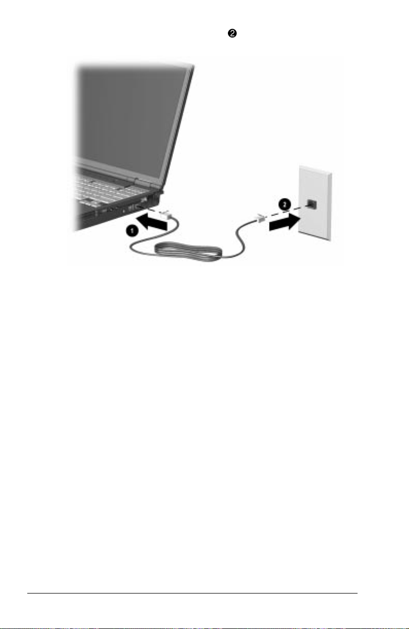
2. Plug the opposite end of the cable 2 into a standard telephone
wall jack.
IMPORTANT: Wall jacks for digital PBX systems may resemble
standard telephone jacks but are not compatible with analog
devices such as modems. Be sure the modem cable is
connected to a regular analog phone line. Plugging the
modem into a digital line will result in no dial tone and is not
recommended. The modem includes protective circuitry
against the digital lines producing excess current. A warning
buzz will sound briefly when excessive current is detected
during a call attempt and the attempt is terminated with the
phone line back on hook..
Selecting Communication Software
You can operate the modem with preinstalled or optional
software. To use preinstalled modem software, select
StartÅPrograms. Then,
■ Select AccessoriesÅHyperTerminal for terminal emulation
and data transfer.
■ In Windows 95 select AccessoriesÅFaxÅCompose New Fax.
■ In Windows 98 or Windows NT 4.0 select RingCentral Fax.
7-2 Using an Internal Modem (Available on Select Models)
Page 88

Using Modem Commands and Dial Modifiers
You can configure most communications software without the
use of AT commands or dial modifiers.
■ If you prefer to configure the modem using AT commands,
select StartÅProgramsÅAccessoriesÅHyperTerminal.
■ To access an AT command set including dial modifiers and
instructions, go to the Compaq Internet site at
http://www.compaq.com/support/portables.
Uninstalling the Modem
To uninstall the modem software and hardware under
Windows NT 4.0, you must log into Windows NT 4.0 with
Administrator privileges. To uninstall the modem software and
hardware under Windows 95, Windows 98, or Windows NT 4.0:
1. Click StartÅSettingsÅControl Panel.
2. Double-click the Add/Remove Programs icon.
3. Select the Compaq internal model from the list of software.
4. Click the Add/Remove button.
5. Click Yes to confirm.
6. If you are prompted to restart the system, click Yes.
Remove the modem hardware from the computer.
Using the Modem While Traveling
Internationally
Using a Country-Specific Modem Adapter
Telephone jacks vary by country. The modem cable included with
the computer plugs directly into an RJ-11 telephone jack. To plug
the modem cable into a different type of telephone jack, you must
use a country-specific modem cable adapter. A cable adapter is
provided with the computer. To obtain the country-specific
adapters required for your itinerary, refer to Appendix A to
contact a Compaq-authorized dealer, reseller, or service provider.
Using an Internal Modem (Available on Select Models) 7-3
Page 89

To connect the modem using a country-specific modem adapter:
1. Plug the end of the modem cable with the EMI suppression
circuitry included with the computer into the RJ-11 jack on
the computer 1.
2. Plug the country-specific modem adapter into the telephone
jack 2.
3. Plug the modem cable into the country-specific modem
adapter 3.
Selecting a Country-Specific Modem Configuration
The internal modem is configured to meet operating approval in
the country where you purchased your computer. If the modem is
used in other countries during travel, the country selection setting
for the modem needs to change to meet the telecommunications
regulations for that country.
Modem country configuration is performed through the country
drop-down box on the Dialing Properties screen of the modem
Control Panel. To confirm that the modem has been approved for
use by the telecommunications agency in the desired country,
check the approvals label on the bottom of the computer. Or, for
the most up-to-date information, refer to the Compaq Internet
Web site at www.compaq.com.
7-4 Using an Internal Modem (Available on Select Models)
Page 90

NOTE: The internal modem supports a subset of the countries that
are listed under the Dialing Properties. If you select an
unsupported country, a warning will appear and USA will be
selected if you don’t choose a different supported country.
You can confirm your country selection if running
Windows 95, Windows 98, or Windows NT 4.0:
Click StartÅSettingsÅControl PanelÅModemsÅDialing
PropertiesÅand then view your country in the “I am in:” dropdown box.
If you are traveling, you can change your country selection if
running Windows 95, Windows 98, or Windows NT 4.0:
Click StartÅSettingsÅControl PanelÅModemsÅDialing
PropertiesÅand then selecting your new country in the “I am in:”
drop-down box.
NOTE: For proper modem operation and to ensure compliance with
local regulatory requirements when traveling, change your
modem country selection whenever you operate your modem in a
different country.
Travel Connection Checklist
If you experience connection problems while using the modem
outside your home country, the following suggestions may help.
■ Check the telephone line type—the modem requires an
analog, not a digital, telephone line. A telephone line described
as a data line, fax machine line, modem line, or standard
telephone line, is probably an analog line.
■ Check for pulse or tone dialing—Dial a few digits on the
telephone and listen for clicks (pulses) or tones. Then set your
communication software to the corresponding dialing mode
(pulse or tone).
■ Check the telephone number you are dialing and the
response of the remote modem—Dial the telephone number
on the telephone, wait for the remote modem to answer, then
hang up.
Using an Internal Modem (Available on Select Models) 7-5
Page 91

■ Set the modem to ignore dial tones—If the modem receives a
dial tone it does not recognize, it will not dial and will display
a No Dial Tone error message. To set the modem to ignore all
dial tones before dialing:
1. Select StartÅSettingsÅControl PanelÅModems.
2. Select your modem, then select PropertiesÅConnections
tab, then clear the Wait for Dial Tone Before Dialing check
box.
NOTE: If you continue to receive the No Dial Tone error
message after clearing the checkbox, click StartÅSettingsÅ
Control PanelÅDialing PropertiesÅselect USA in the “I am
in:” drop-down box, then again clear the Wait for Dial Tone
Before Dialing check box.
7-6 Using an Internal Modem (Available on Select Models)
Page 92

chapter
8
CONNECTING EXTERNAL DEVICES
Connecting an External Enhanced Keyboard
To connect an external enhanced keyboard to the computer,
connect the keyboard cable to the keyboard/mouse connector on
the computer.
Connecting an External Monitor
CAUTION: To prevent damage to the computer, turn off the monitor
before connecting it to the computer or disconnecting it from the
computer. To prevent damage to the computer display, do not place
an external monitor or any other object on top of the computer when
the computer is closed.
To connect an external VGA monitor:
1. Turn off the monitor.
2. Plug the monitor signal cable into the external monitor
connector on the back of the computer.
3. Plug the monitor power cord into a properly grounded
electrical outlet.
4. Turn on the monitor.
5. Ensure that the computer recognizes your monitor type. Click
StartÅSettingsÅControl Panel then double-click Display.
Select the appropriate manufacturer and model, if necessary.
NOTE: If the external monitor does not immediately show a
display, try using the
Fn+F4 hotkeys.
Connecting External Devices 8-1
Page 93

Connecting a Television Monitor
CAUTION: To prevent damage to the computer display, do not place
a television monitor or any other object on top of the computer when
the computer is closed.
A Composite TV-Out is provided that allows you to switch your
screen output from the computer display (panel and/or monitor)
to a television monitor. To switch your computer output to the
television monitor, use the Microsoft Windows Control Panel.
1. Turn off the television and plug the RCA-style television
signal cable into the Composite TV-Out on the computer.
NOTE: You can purchase an RCA-style television signal cable
at any home electronics store.
2. Plug the television power cord into a properly grounded
electrical outlet.
3. If you are running Windows 95 or later: to ensure that the
computer recognizes your television format, click Start
ÅSettingsÅControl PanelÅDisplay. Select the Settings tab,
then the Advanced options. Click the Displays tab and select
TV. Select the appropriate television format (NTSC, NTSC-J,
PAL, or PAL-M).
If you are running Windows NT 4.0: to ensure that the
computer recognizes your television format, click
StartÅProgramsÅ ATI UtilitiesÅATI Display Utility. Select
the appropriate television format (NTSC, NTSC-J, PAL, or
PAL-M).
4. Turn on the television.
5. If the television does not display the correct image, repeat
Step 3 and select a different television format.
6. To switch back to the computer display, toggle the
hotkeys back to the panel and/or monitor display mode, or
follow the sequence in Step 3 and select Panel and/or
Monitor.
Fn+F4
8-2 Connecting External Devices
Page 94

Connecting a Mouse or Other External
Pointing Device
A PS/2-compatible mouse or external TouchPad can be connected
to the computer.
To connect an external pointing device, insert the pointing device
cable into the keyboard/mouse connector.
External pointing devices need software device drivers to operate.
The necessary drivers should be provided by the manufacturer or
may be preinstalled with Microsoft Windows.
Connecting a Serial Printer
1. Turn off the printer.
2. Plug the printer end of the printer signal cable into the printer.
3. Connect the serial printer signal cable to the serial connector
on the back of the computer.
4. Plug the printer power cord into a properly grounded
electrical outlet.
5. Turn on the printer and resume your work.
NOTE: Windows should prompt you to set up your printer before
printing for the first time. If setup fails, consult the printer
documentation for printer device driver configuration information
and instructions.
Connecting a Parallel Printer
1. Turn off the printer.
2. Plug the printer end of the printer signal cable into the printer.
3. Connect the parallel printer signal cable to the parallel
connector on the back of the computer.
4. Plug the printer power cord into a properly grounded
electrical outlet.
5. Turn on the printer and resume your work.
NOTE: Windows should prompt you to set up your printer before
printing for the first time. If setup fails, you may need to consult
the printer documentation for printer device driver configuration
information and instructions.
Connecting External Devices 8-3
Page 95

Connecting Infrared Equipment
NOTE: Infrared-equipped computers are IrDA-compliant. Infrared
performance may vary depending on peripherals, distance
between infrared devices, and applications used. The infrared port
is available only on specific models.
The infrared port allows wireless communication between your
computer and other infrared-equipped devices. Operating system
support for infrared communication is currently available with
Microsoft Windows 95 and Windows 98, but not for
Windows NT 4.0. To operate infrared on computers running
Windows NT 4.0, you will need to purchase optional software.
The infrared port produces an invisible beam of infrared light to
communicate with another infrared-equipped device.
To establish an infrared link:
■ Be sure the infrared ports on both devices are turned on and
facing each other at a distance no greater than 1.5 feet (about
0.5 meter).
■ Avoid moving the infrared ports away from each other during
data transmission.
■ Avoid interference from remote control units, such as wireless
headphones or audio devices, pointed at the infrared ports.
■ Avoid direct sunlight, fluorescent light, or flashing
incandescent light close to the infrared ports.
■ Keep the path between the infrared ports free of any objects
that might interfere with data transmission.
■ Do not point one of the ports more than 30 degrees (plus or
minus 15 degrees off the center line) away from the infrared
port of the device you are connecting with.
8-4 Connecting External Devices
Page 96

Configuring the Infrared Port
As you set up your infrared software, the following information
may be helpful.
■ The infrared port default settings are: Port, COM3; address, 3;
Interrupt Request (IRQ), 3.
■ If you use Direct Cable Connection and the utility asks you to
choose a port for the infrared connection, you can select Serial
Cable on COM5 or, if the computer is running a preinstalled
Windows 95 or Windows 98 operating system, select Parallel
Cable on LPT3.
Enabling the Infrared Port
In Windows 95 the infrared port must be enabled each time the
computer is turned on or restarted. To enable the infrared port,
select StartÅSettingsÅControl PanelÅInfrared.
In Windows 98 the infrared port is enabled by default each time
the computer starts up.
■ When the infrared port is enabled, the infrared icon appears on
the taskbar and Infrared Monitor Search is enabled by default.
■ While the Infrared Monitor Search is enabled
❏ You can establish an infrared link.
❏ The system cannot initiate Suspend (Standby). User-
initiated Suspend (Standby) is not affected.
■ When the Infrared Monitor Search is disabled
❏ Power is conserved.
❏ You cannot establish an infrared link.
❏ The system can initiate Suspend (Standby).
Connecting External Devices 8-5
Page 97

Connecting USB Peripherals
Your computer comes equipped with a port that connects
Universal Serial Bus (USB) devices to the computer.
Your computer can support certain USB devices without any
special drivers. These include hubs and keyboards. To connect
USB devices for which the device manufacturer provided no
special drivers, you will need an operating system that has USB
support, such as Windows 95 or Windows 98 preinstalled by
Compaq. Later versions of the Windows operating systems will
add functionality that may allow you to attach any USB device to
your computer (for example, a video camera) and allow many
USB devices to be connected and working simultaneously.
A USB keyboard and mouse, optionally connected through a hub,
offer the same functionality as a standard keyboard and mouse
connected through the keyboard/mouse connector. Future
operating systems will have extended USB capabilities which will
replace the USB capabilities built into the computer.
Connecting to a Docking Device
The computer is compatible with Armada docking stations. To
connect the computer to a port replicator or docking station, refer
to the instructions that came with the docking device.
8-6 Connecting External Devices
Page 98

chapter
9
USING PC CARDS
PC Card Types
This computer can support two Type II PC Cards or one Type III
PC Card. It supports both 16-bit and 32-bit CardBus PC Cards.
Several kinds of PC Cards are supported, such as network cards,
hard drive cards, memory cards, and fax/modem cards.
For a current list of third-party PC Cards qualified on this
computer, call your Compaq authorized dealer, reseller, or service
provider.
Inserting a PC Card
1. If you are running Windows NT 4.0 but not CardWare 5.0
provided by Compaq, turn off the computer. If you are
running Windows 95, you do not need to turn off the
computer or initiate Suspend before inserting a PC Card.
NOTE: If you are running Windows NT 4.0 and CardWare 5.0
provided by Compaq, most PC Cards can be inserted while
the computer is on. Contact your PC Card vendor directly for
information about the level of support they offer for hot
insertion with CardWare 5.0.
Using PC Cards 9-1
Page 99

2. With the label side up, insert the 68-pin connector side of the
PC Card into the PC Card slot, pushing gently until firmly
seated.
CAUTION: To prevent damage to the connectors, use minimal
pressure when inserting a PC Card into a PC Card slot.
If you are running Windows 95 or Windows 98 and your
computer is on, the computer automatically configures a plug and
play card and most other PC Cards. If the computer is turned off
or in Suspend, a card is not configured until you turn on the
computer or exit Suspend.
Windows NT 4.0 is not a plug and play operating system at this
time. If you are running Windows NT 4.0, the computer
configures a card only when it is on at the time the PC Card is
inserted into the PC Card slot. The computer only recognizes that
a PC Card has been removed if the PC Card slot is empty when
the computer is powered on or the PC Card slot is empty at
startup.
After the computer has configured the card, the computer beeps
twice to indicate that the card is ready for use.
IMPORTANT: After the PC Card has been inserted and configured, it
may be necessary to perform an initial setup procedure. For
example, a new storage card may need to be formatted, or a new
network card may need drivers installed. For detailed information
on setup procedures for various network PC Cards, refer to the
instructions provided by the PC Card manufacturer.
9-2 Using PC Cards
Page 100

Removing a PC Card
1. If you are running Windows 95 or Windows 98, you must
stop the PC Card before removing it (see “Stopping a
PC Card” later in this chapter). You do not need to turn the
computer off or initiate Suspend. If you are running
Windows NT 4.0, you must close Windows NT 4.0 and turn
off the computer.
CAUTION: Failure to stop a PC Card before removing it may
cause loss of data.
2. To release the PC Card eject button, depress the button
once. To eject the PC Card, firmly depress the PC Card eject
button a second time.
3. Remove the card 2.
NOTE: If you are running Windows 95, the computer beeps twice if
it is turned on when the PC Card is removed.
1
Using PC Cards 9-3
 Loading...