

Page 1

HP ProLiant BL e-Class System
Setup and Installation Guide
May 2003 (Third Edition)
Part Number 249068-003
Page 2

© 2002, 2003 Hewlett-Packard Development Company, L.P.
Microsoft® and Windows® are US registered trademarks of Microsoft Corporation.
Intel® and Pentium® are trademarks or registered trademarks of Intel Corporation in the US
and other countries and are used under license.
Hewlett-Packard Company shall not be liable for technical or editorial errors or omissions
contained herein. The information in this document is provided “as is” without warranty of
any kind and is subject to change without notice. The warranties for HP products are set forth
in the express limited warranty statements accompanying such products. Nothing herein
should be construed as constituting an additional warranty.
HP ProLiant BL e-Class System Setup and Installation Guide
May 2003 (Third Edition)
Part Number 249068-003
Page 3

Contents
About This Guide
Audience Assumptions...................................................................................................... xi
Important Safety Information ............................................................................................ xi
Symbols on Equipment ..................................................................................................... xi
Rack Stability .................................................................................................................. xiii
Symbols in Text............................................................................................................... xiii
Related Documents.......................................................................................................... xiv
Getting Help ....................................................................................................................xiv
Technical Support ..................................................................................................... xiv
HP Website .................................................................................................................xv
Authorized Reseller ....................................................................................................xv
Reader’s Comments ..........................................................................................................xv
Chapter 1
System Features
ProLiant BL e-Class System Technology ....................................................................... 1-1
Hardware Features........................................................................................................... 1-3
ProLiant BL e-Class Server Blade Enclosure Features ............................................ 1-4
ProLiant BL e-Class Server Blade Features ............................................................. 1-7
Software Deployment and Management Features......................................................... 1-11
Diagnostic Features ....................................................................................................... 1-14
Pre-Failure Warranty..................................................................................................... 1-14
Chapter 2
Planning the Installation
Optimum Environment.................................................................................................... 2-1
Rack Warnings ................................................................................................................ 2-2
HP ProLiant BL e-Class System Setup and Installation Guide iii
Page 4

Contents
ProLiant BL e-Class Server Blade Enclosure Warnings and Cautions............................2-4
Preparing for Software Deployment ................................................................................2-6
Rapid Deployment Pack............................................................................................2-6
Alternate Deployment Method..................................................................................2-6
Shipping Contents............................................................................................................2-6
Server Blade Enclosure .............................................................................................2-7
Rack Mounting Hardware .........................................................................................2-8
Server Blades.............................................................................................................2-9
Interconnect Trays.....................................................................................................2-9
Optional Installation Service..........................................................................................2-10
Chapter 3
Installing and Cabling the System
Installing the Interconnect Tray ....................................................................................... 3-2
Measuring with the Rack Template .................................................................................3-6
Installing the Rack Rails .................................................................................................. 3-8
Installing the Enclosure into the Rack ...........................................................................3-11
Cabling the ProLiant BL e-Class System ......................................................................3-14
Identifying Interconnect Tray Connectors...............................................................3-15
Cabling the Enclosure .............................................................................................3-18
Powering Up the ProLiant BL e-Class System..............................................................3-23
Powering Down the ProLiant BL e-Class System......................................................... 3-23
Powering Down a Server Blade ..............................................................................3-24
Powering Down the Enclosure ................................................................................ 3-25
Installing a Server Blade................................................................................................3-25
Removing a Server Blade ..............................................................................................3-29
Installing Additional Memory........................................................................................3-30
Attaching the Diagnostic Adapter.................................................................................. 3-35
Chapter 4
Deployment and Management
ProLiant BL e-Class Server Blade Deployment Options.................................................4-2
Automated Deployment Using HP ProLiant Essentials Rapid Deployment Pack....4-2
Alternate Deployment Methods ................................................................................4-3
Diagnostic Adapter.................................................................................................... 4-4
ProLiant BL e-Class Server Blade Supported Software Utilities ....................................4-4
Supported Operating Systems ...................................................................................4-4
iv HP ProLiant BL e-Class System Setup and Installation Guide
Page 5

ROM-Based Setup Utility......................................................................................... 4-5
Redundant ROM Support ......................................................................................... 4-6
Flashing the Server Blade ROM ............................................................................... 4-8
ProLiant BL e-Class Integrated Administrator ....................................................... 4-10
Server Blade Event Messages................................................................................. 4-13
Insight Manager 7 ................................................................................................... 4-15
Survey Utility.......................................................................................................... 4-16
ProLiant BL e-Class C-GbE Interconnect Switch (Option) Management Tools
and Utilities............................................................................................................. 4-16
Appendix A
Regulatory Compliance Notices
Regulatory Compliance Identification Numbers............................................................ A-1
Federal Communications Commission Notice............................................................... A-1
Class A Equipment .................................................................................................. A-2
Class B Equipment................................................................................................... A-2
Declaration of Conformity for Products Marked with the FCC Logo,
United States Only ................................................................................................... A-3
Modifications ........................................................................................................... A-3
Cables....................................................................................................................... A-4
Canadian Notice (Avis Canadien) .................................................................................. A-4
Class A Equipment .................................................................................................. A-4
Class B Equipment................................................................................................... A-4
Mouse Compliance Statement........................................................................................ A-4
European Union Notice .................................................................................................. A-5
Japanese Notice .............................................................................................................. A-6
BSMI Notice................................................................................................................... A-6
Compliance with CDRH Regulations ............................................................................ A-7
Compliance with International Regulations ................................................................... A-7
Battery Replacement Notice........................................................................................... A-7
Contents
Appendix B
Electrostatic Discharge
Preventing Electrostatic Damage ....................................................................................B-1
Grounding Methods.........................................................................................................B-2
HP ProLiant BL e-Class System Setup and Installation Guide v
Page 6

Contents
Appendix C
Error Messages
Appendix D
Troubleshooting
When the Enclosure Does Not Start ...............................................................................D-3
Enclosure Diagnostic Steps............................................................................................. D-4
When the Server Blade Does Not Start......................................................................... D-14
Server Blade Diagnostic Steps......................................................................................D-15
Problems After Initial Boot........................................................................................... D-19
Other Information Resources........................................................................................ D-20
Appendix E
LEDs and Switches
LEDs ............................................................................................................................... E-1
Enclosure Front Panel LEDs .................................................................................... E-2
Enclosure Rear Panel LEDs ..................................................................................... E-3
Fan Health LEDs.................................................................................................... E-12
Server Blade and Diagnostic Adapter LEDs .......................................................... E-13
Switches........................................................................................................................E-15
Front Panel ............................................................................................................. E-16
Rear Panel .............................................................................................................. E-17
Server Blade Maintenance Switch ......................................................................... E-18
Appendix F
Specifications
Server Blade Enclosure....................................................................................................F-2
Hot-Plug Power Supply ...................................................................................................F-3
Appendix G
System Battery
Server Blade Battery Replacement .................................................................................G-1
Index
vi HP ProLiant BL e-Class System Setup and Installation Guide
Page 7

Contents
List of Figures
1-1 ProLiant BL e-Class server blade enclosure with ProLiant BL e-Class server
blades (20)................................................................................................................. 1-3
1-2 ProLiant BL10e server blade .................................................................................... 1-7
1-3 ProLiant BL10e G2 server blade .............................................................................. 1-7
2-1 ProLiant BL e-Class standard rack mounting hardware ........................................... 2-8
2-2 The available interconnect trays ............................................................................... 2-9
3-1 Removing a hot-plug power supply.......................................................................... 3-2
3-2 Pulling the interconnect tray ejector levers............................................................... 3-3
3-3 Inserting the interconnect tray and engaging the interconnect tray levers................ 3-4
3-4 Installing a hot-plug power supply ........................................................................... 3-5
3-5 Measuring with the ProLiant BL e-Class rack template ........................................... 3-6
3-6 Marking the rack for ProLiant BL e-Class system installation................................. 3-7
3-7 Unlocking and adjusting a rack rail .......................................................................... 3-8
3-8 Inserting the rear of the rack rail............................................................................... 3-9
3-9 Inserting the front of the rack rail and engaging the locking gear .......................... 3-10
3-10 Installing the enclosure into the rack ...................................................................... 3-12
3-11 Removing a thumbscrew and hexagonal washer .................................................... 3-13
3-12 Replacing a thumbscrew, spring, and hexagonal washer........................................ 3-14
3-13 Interconnect switch connectors............................................................................... 3-15
3-14 RJ-21 patch panel connectors ................................................................................. 3-16
3-15 RJ-45 patch panel connectors ................................................................................. 3-17
3-16 Cabling the system with the interconnect switch.................................................... 3-20
3-17 Cabling the system with the RJ-21 patch panel ...................................................... 3-21
3-18 Cabling the system with the RJ-45 patch panel ...................................................... 3-21
3-19 Powering down the server blade ............................................................................. 3-24
3-20 Removing a single-bay server blade blank ............................................................. 3-26
3-21 Removing a five-bay server blade blank................................................................. 3-27
3-22 Installing a server blade .......................................................................................... 3-28
3-23 Removing a server blade......................................................................................... 3-29
3-24 ProLiant BL10e server blade DIMM socket keys .................................................. 3-31
3-25 ProLiant BL10e G2 server blade DIMM socket keys............................................. 3-32
3-26 Removing a DIMM................................................................................................. 3-33
3-27 Installing a DIMM .................................................................................................. 3-34
3-28 Attaching the diagnostic adapter............................................................................. 3-35
3-29 Connectors on the diagnostic adapter ..................................................................... 3-36
HP ProLiant BL e-Class System Setup and Installation Guide vii
Page 8

Contents
E-1 Enclosure front panel LEDs ..................................................................................... E-2
E-2 Rear panel LEDS with interconnect switch.............................................................. E-3
E-3 Rear panel LEDs with RJ-21 patch panel................................................................. E-6
E-4 Rear panel LEDs with RJ-45 patch panel................................................................. E-9
E-5 Hot-plug fan health LEDs ...................................................................................... E-12
E-6 Server blade LEDs ................................................................................................. E-13
E-7 Diagnostic adapter LEDs........................................................................................ E-13
E-8 Enclosure front panel buttons................................................................................. E-16
E-9 Enclosure rear panel buttons .................................................................................. E-17
E-10 Server blade maintenance switches ........................................................................ E-18
G-1 Locating and removing the battery on the server blade ...........................................G-2
G-2 Installing the new battery .........................................................................................G-3
List of Tables
2-1 ProLiant BL e-Class Standard Rack Mounting Hardware ........................................2-8
2-2 Interconnect Tray Configurations ...........................................................................2-10
3-1 Interconnect Switch Connectors.............................................................................. 3-16
3-2 RJ-21 Patch Panel Connectors ................................................................................3-17
3-3 RJ-45 Patch Panel Connectors ................................................................................3-18
3-4 Cable Pinout (Sample for Server Blades 1 through 10 NIC 1) ...............................3-22
3-5 Cable Pinout for a Null-Modem Cable....................................................................3-23
3-6 Connectors on the Diagnostic Adapter.................................................................... 3-36
4-1 ROM-Based Setup Utility Default Settings ..............................................................4-5
4-2 Server Blade Event Messages .................................................................................4-13
D-1 Enclosure Diagnostic Steps ...................................................................................... D-5
D-2 Is the Power LED on Both Power Supplies Solid Green?........................................ D-5
D-3 Is the Fault LED on Both Power Supplies Off? .......................................................D-7
D-4 Is the Enclosure Power LED on the Rear Panel Green?........................................... D-9
D-5 Is the Enclosure Health LED on the Front of the Enclosure On?........................... D-10
D-6 Is the Local Management Console Displaying Information When Connected
to the Enclosure? ....................................................................................................D-11
D-7 Is the Integrated Administrator Health LED Green?.............................................. D-12
D-8 Is the Fan Health LED Green? ............................................................................... D-13
D-9 Server Blade Diagnostic Steps ............................................................................... D-15
D-10 Is the Power LED on the Server Blade Green? ......................................................D-16
D-11 Is the Health LED on the Server Blade Green?...................................................... D-17
D-12 Is the NIC 1 or NIC 2 LED on the Server Blade Illuminated?............................... D-18
viii HP ProLiant BL e-Class System Setup and Installation Guide
Page 9

Contents
D-13 Is the Monitor Displaying Information When Connected to the Server Blade
Through the Diagnostic Adapter?.......................................................................... D-18
D-14 Problems After Initial Boot.................................................................................... D-19
D-15 Troubleshooting Resources.................................................................................... D-20
E-1 Enclosure Front Panel LEDs..................................................................................... E-2
E-2 Rear Panel LEDs with Interconnect Switch.............................................................. E-4
E-3 Rear Panel LEDs with RJ-21 Patch Panel ................................................................E-7
E-4 Rear Panel LEDs with RJ-45 Patch Panel ..............................................................E-10
E-5 Hot-Plug Fan Health LEDs.....................................................................................E-12
E-6 Server Blade and Diagnostic Adapter LEDs...........................................................E-14
E-7 Enclosure Front Panel Buttons................................................................................E-16
E-8 Enclosure Rear Panel Buttons................................................................................. E-17
E-9 Server Blade Maintenance Switches....................................................................... E-18
F-1 Enclosure Operating and Performance Specifications .............................................. F-2
F-2 Hot-Plug Power Supply Operating and Performance Specifications........................ F-3
HP ProLiant BL e-Class System Setup and Installation Guide ix
Page 10

This guide provides step-by-step instructions for installation and reference
information for operation, troubleshooting, and future upgrades for the HP ProLiant
BL e-Class system.
Audience Assumptions
This guide is for the person who installs, administers, and troubleshoots servers. HP
assumes you are qualified in the servicing of computer equipment and trained in
recognizing hazards in products with hazardous energy levels.
About This Guide
Important Safety Information
Before installing this product, read the Important Safety Information document
included with the server.
Symbols on Equipment
The following symbols may be placed on equipment to indicate the presence of
potentially hazardous conditions:
WARNING: This symbol, in conjunction with any of the following symbols,
indicates the presence of a potential hazard. The potential for injury exists if
warnings are not observed. Consult the documentation for specific details.
HP ProLiant BL e-Class System Setup and Installation Guide xi
Page 11

About This Guide
Weight in kg
Weight in lb
This symbol indicates the presence of hazardous energy circuits or electric
shock hazards. Refer all servicing to qualified personnel.
WARNING: To reduce the risk of injury from electric shock hazards, do not
open this enclosure. Refer all maintenance, upgrades, and servicing to
qualified personnel.
This symbol indicates the presence of electric shock hazards. The area
contains no user or field serviceable parts. Do not open for any reason.
WARNING: To reduce the risk of injury from electric shock hazards, do not
open this enclosure.
This symbol on an RJ-45 receptacle indicates a network interface connection.
WARNING: To reduce the risk of electric shock, fire, or damage to the
equipment, do not plug telephone or telecommunications connectors into this
receptacle.
This symbol indicates the presence of a hot surface or hot component. If this
surface is contacted, the potential for injury exists.
WARNING: To reduce the risk of injury from a hot component, allow the
surface to cool before touching.
These symbols, on power supplies or systems, indicate that the
equipment is supplied by multiple sources of power.
WARNING: To reduce the risk of injury from electric shock,
remove all power cords to completely disconnect power from the
system.
This symbol indicates that the component exceeds the recommended
weight for one individual to handle safely.
WARNING: To reduce the risk of personal injury or damage to the
equipment, observe local occupational health and safety requirements
and guidelines for manual material handling.
xii HP ProLiant BL e-Class System Setup and Installation Guide
Page 12
Rack Stability
WARNING: To reduce the risk of personal injury or damage to the equipment,
be sure that:
• The leveling jacks are extended to the floor.
• The full weight of the rack rests on the leveling jacks.
• The stabilizing feet are attached to the rack if it is a single-rack installation.
• The racks are coupled together in multiple-rack installations.
• Only one component is extended at a time. A rack may become unstable if
more than one component is extended for any reason.
Symbols in Text
These symbols may be found in the text of this guide. They have the following
meanings.
WARNING: Text set off in this manner indicates that failure to follow directions
in the warning could result in bodily harm or loss of life.
About This Guide
CAUTION: Text set off in this manner indicates that failure to follow directions could
result in damage to equipment or loss of information.
IMPORTANT: Text set off in this manner presents essential information to explain a concept
or complete a task.
NOTE: Text set off in this manner presents additional information to emphasize or supplement
important points of the main text.
HP ProLiant BL e-Class System Setup and Installation Guide xiii
Page 13

About This Guide
Related Documents
For additional information on the topics covered in this guide, refer to the following
documents:
• HP ProLiant BL e-Class System Maintenance and Service Guide
• HP ProLiant BL e-Class System Hardware Installation and Configuration poster
• HP ProLiant BL e-Class Integrated Administrator User Guide
• ProLiant Integration Module for Altiris eXpress User Guide
• HP Servers Troubleshooting Guide
• HP ROM-Based Setup Utility User Guide
• HP ProLiant BL e-Class C-GbE Interconnect Switch User Guide
• White paper: HP ProLiant BL e-Class System Overview and Planning
• White paper: Configuring a Preboot eXecution Environment (PXE) using Red
Hat Linux 7.2 on ProLiant Servers
• QuickSpecs
Getting Help
If you have a problem and have exhausted the information in this guide, you can get
further information and other help in the following locations.
Technical Support
In North America, call the HP Technical Support Phone Center at 1-800-652-6672.
This service is available 24 hours a day, 7 days a week. For continuous quality
improvement, calls may be recorded or monitored. Outside North America, call the
nearest HP Technical Support Phone Center. Telephone numbers for worldwide
Technical Support Centers are listed on the HP website, www.hp.com.
Refer to the HP Servers Troubleshooting Guide for a list of information you need
before contacting HP.
xiv HP ProLiant BL e-Class System Setup and Installation Guide
Page 14

HP Website
The HP website has information on this product as well as the latest drivers and flash
ROM images. You can access the HP website at www.hp.com.
Authorized Reseller
For the name of the nearest authorized reseller:
• In the United States, call 1-800-345-1518.
• In Canada, call 1-800-263-5868.
• Elsewhere, see the HP website for locations and telephone numbers.
Reader’s Comments
HP welcomes your comments on this guide. Please send your comments and
suggestions by e-mail to ServerDocumentation@hp.com.
About This Guide
HP ProLiant BL e-Class System Setup and Installation Guide xv
Page 15

System Features
The HP ProLiant BL e-Class server blade system offers space- and power-efficient
performance and serviceability in a 3U rack-mounted enclosure. This state-of-the-art
modular system supports rapid server configuration and deployment flexibility.
ProLiant BL e-Class System Technology
The ProLiant BL e-Class system offers the following key technological advantages:
•
Higher density for space efficiency (up to 280 single-processor ProLiant
BL e-Class server blades in a 42U rack)
1
•
Rapid deployment and redeployment
— Snap-in, toolless installation of rack components and server blades
— Reduced number of rack components
— Interconnect tray options to customize network cabling
•
Power efficiency in an ultra-low voltage processor
•
Integrated remote management and Web-based systems management, including
headless operation
•
Support for ProLiant Essentials Rapid Deployment Pack
— Graphical console for software installation
— Flexibility for imaging and scripted installs
— Simultaneous deployment of many servers with minimal network load
HP ProLiant BL e-Class System Setup and Installation Guide 1-1
Page 16

System Features
• Configuration flexibility and scalability
— Support for partial rack and partial enclosure installations
— Compatibility with HP, Compaq branded, telco, and third-party racks
• • High availability
— Redundant hot-plug power supplies
— Redundant hot-plug fans
— Two embedded NICs available for LAN segmentation, network fault
Rapid servicing
— Modular component design enables easy upgrades and service
— Major components accessible from the front and rear of the enclosure
— Support for in-rack diagnostic methods
tolerance, or load balancing
1-2 HP ProLiant BL e-Class System Setup and Installation Guide
Page 17
Hardware Features
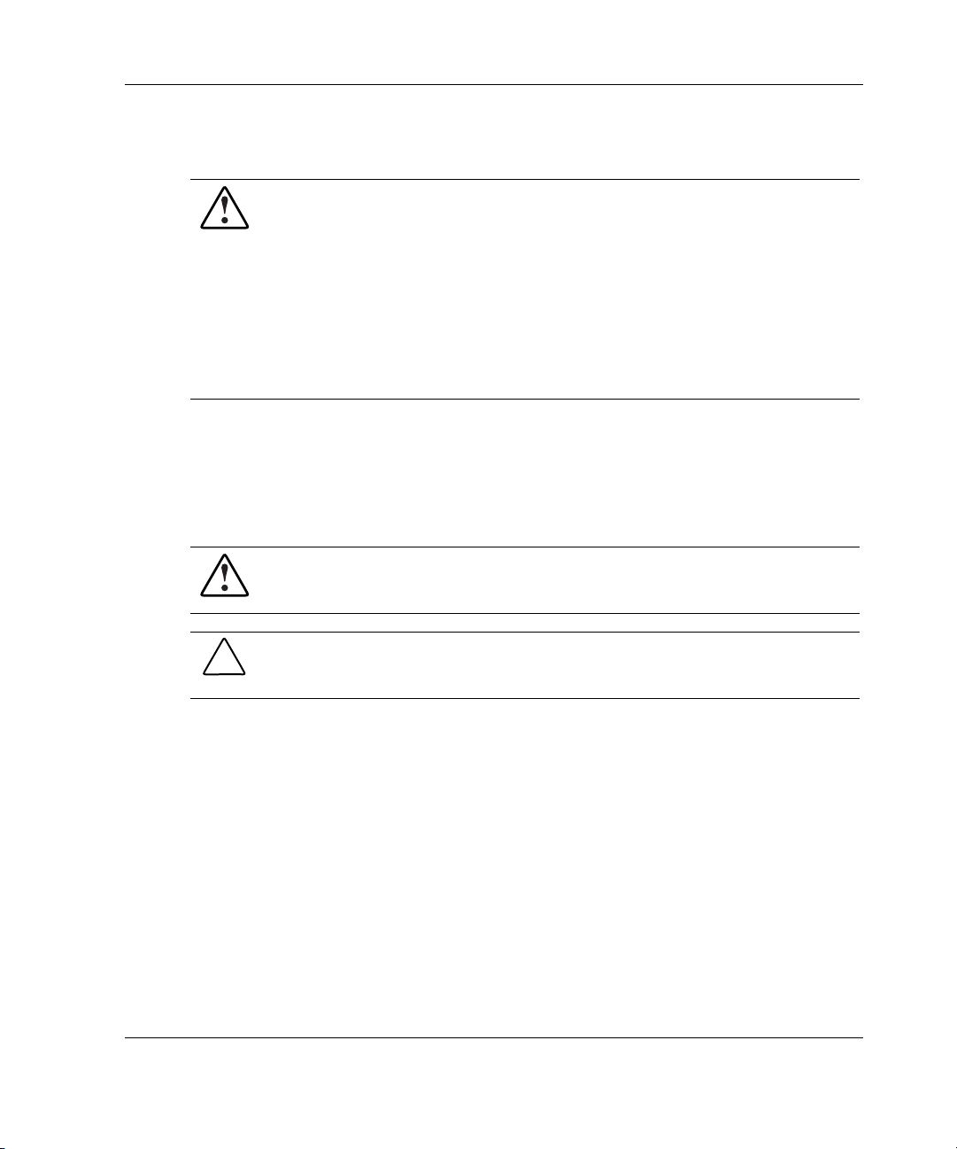
The ProLiant BL e-Class system is comprised of a rack-mount server blade enclosure
that contains advanced electronics for managing up to 20 single-processor
ProLiant BL e-Class server blades.
Figure 1-1: ProLiant BL e-Class server blade enclosure
with ProLiant BL e-Class server blades (20)
System Features
The enclosure and server blade features described in the following sections are
standard on all ProLiant BL e-Class systems, unless otherwise specified.
HP ProLiant BL e-Class System Setup and Installation Guide 1-3
Page 18

System Features
ProLiant BL e-Class Server Blade Enclosure Features
Server blade enclosure features include:
•
3U height and standard 48 cm (19 in) width
•
Support for up to 20 server blades
•
Choice of interconnect tray option:
— Interconnect switch with four Gigabit Ethernet uplink connectors
— Patch panel with four RJ-21 connectors
— Patch panel with 40 RJ-45 connectors
•
ProLiant BL e-Class Integrated Administrator for local and remote management
and monitoring
•
Redundant power
•
Redundant cooling
•
System health LEDs
ProLiant BL e-Class Integrated Administrator
ProLiant BL e-Class Integrated Administrator features include:
•
Local and remote access to enclosure and server blade information
•
Secure Shell, Telnet, and Secure Sockets Layer (SSL) Web access
•
Remote power on/off/reboot and Unit Identification (UID) controls
•
Access to any server blade remote console
•
Access to any server blade ROM-Based Setup Utility (RBSU)
•
Support for command line scripting
•
Upgradeable firmware
1-4 HP ProLiant BL e-Class System Setup and Installation Guide
Page 19

Redundant Power
The server blade enclosure includes two 600-W redundant hot-plug power supplies
with:
•
1 + 1 redundancy
•
Integrated hot-plug capability
•
Autosensing input voltage range from 100 to 127 VAC and 200 to 240 VAC
•
Load-sharing across all server blades
Redundant Cooling
The server blade enclosure ships with four redundant hot-plug fans. These fans offer:
•
2 + 2 redundancy
•
Hot-swapping among all fan positions
•
Variable-speed fans
•
Individual fan status LEDs
System Features
ProLiant BL e-Class C-GbE Interconnect Switch (Option)
The ProLiant BL e-Class C-GbE Interconnect Switch benefits include:
•
Significant cable reduction (40 server blade NIC connections to 4 Gigabit
Ethernet uplink connectors)
•
Interconnect tray form factor that fits into server blade enclosure
•
Low wattage for maximum power efficiency
•
Compatibility with common core switches
•
Two separate switches providing redundant paths to each server blade
HP ProLiant BL e-Class System Setup and Installation Guide 1-5
Page 20

System Features
System Health LEDs
System health information is displayed locally through a full set of system LEDs,
including:
• • Internal fan health LEDs
External health LEDs
— Fan health LED
— Enclosure health LED
— Server blade LEDs
— Power supply LEDs
— Integrated Administrator health LED
1-6 HP ProLiant BL e-Class System Setup and Installation Guide
Page 21
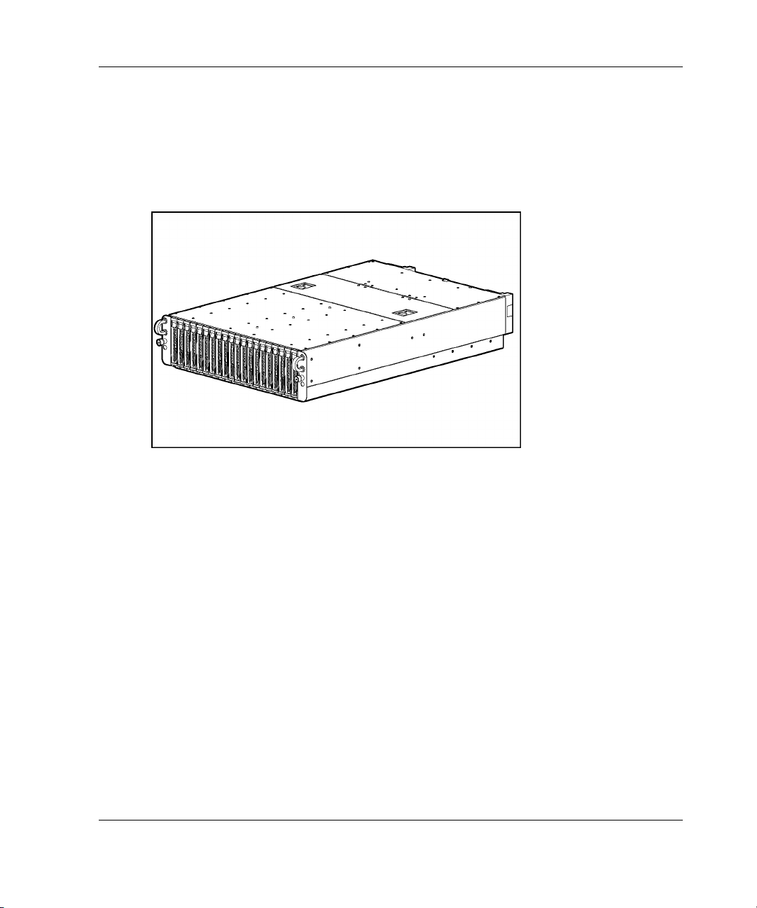
ProLiant BL e-Class Server Blade Features
The ProLiant BL e-Class server blades are simple to install, deploy, and service. A
server blade that requires out-of-the-rack upgrades, service, or maintenance can be
easily replaced by another server blade.
Figure 1-2: ProLiant BL10e server blade
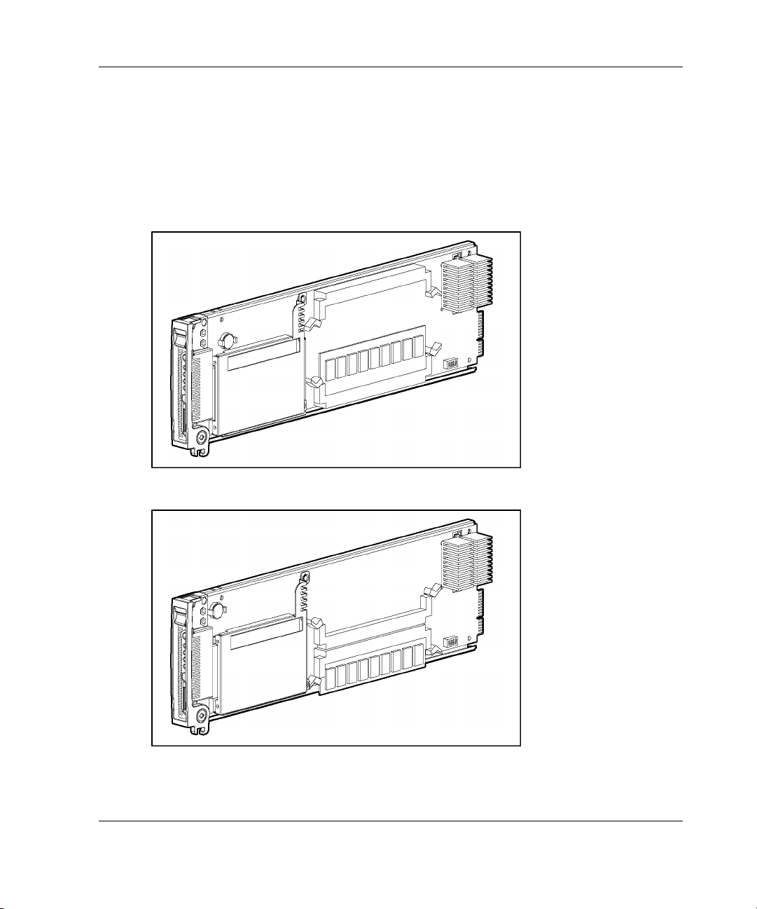
System Features
Figure 1-3: ProLiant BL10e G2 server blade
HP ProLiant BL e-Class System Setup and Installation Guide 1-7
Page 22

System Features
All ProLiant BL e-Class server blades support server system architecture technology,
including the following:
•
Processor
•
Memory
•
Mass storage with Self-Monitoring Analysis and Reporting Technology
(S.M.A.R.T.)
•
Server blade status and monitoring
•
Video
•
ROM
•
NICs
Processor
Each ProLiant BL10e server blade ships with an integrated ultra low voltage Intel®
Pentium® III processor with 512 K cache. Each ProLiant BL10e G2 server blade
ships with an integrated ultra-low voltage Intel Pentium M processor with 1 MB
cache.
CAUTION: The processor heatsink assembly is integrated into the system board
and cannot be removed.
Memory
The server blade supports the following memory features:
• • Registered SDRAM memory for the ProLiant BL10e server blade; Registered
DDR SDRAM memory for the ProLiant BL10e G2 server blade
For more information, refer to QuickSpecs located on the HP website:
www.hp.com
ECC memory
— Detects and corrects single-bit memory errors
1-8 HP ProLiant BL e-Class System Setup and Installation Guide
Page 23

— Detects multi-bit memory errors
•
System memory expandable to 1 GB
•
Two DIMM slots
Mass Storage
The server blade ships with one ATA hard drive attached with screws. Each hard
drive features S.M.A.R.T.
S.M.A.R.T. is a drive-level function that notifies Insight Manager 7 of an impending
hard drive failure. S.M.A.R.T. is part of the Pre-Failure Warranty, and enables a
problematic drive to be replaced before the actual failure occurs.
Server Blade Status and Monitoring
A server blade provides the following status and monitoring features:
•
Server blade UID LED and button
•
Server blade health LED
System Features
•
Server blade network activity LEDs
•
Hard drive activity LED
•
Power button and LED
•
Diagnostic support through ROM-Based Setup Utility (RBSU), the Integrated
Management Log (IML), health driver, and Insight Manager 7
Diagnostic Adapter
Each server blade has a diagnostic connector that delivers the following capabilities
using the diagnostic adapter that ships with the enclosure:
•
USB connectivity for two USB devices including diskette drive, CD-ROM drive,
keyboard, and mouse
•
PS/2 connectivity for keyboard and mouse
•
Video connectivity through a standard 15-pin VGA connector
HP ProLiant BL e-Class System Setup and Installation Guide 1-9
Page 24

System Features
• Serial connectivity using a DB-9 connector
Video
The ProLiant BL e-Class server blades support video through the diagnostic adapter.
Video features include:
•
Support for SVGA, VGA, and EGA graphics resolution
•
8-MB SDRAM video memory
ROM
ProLiant BL e-Class server blade ROM features include:
•
Redundant ROM support
•
Integrated RBSU support
•
ROMPaq Utility used to upgrade the system ROM
•
Hardware boot block protection
•
Remote ROM flash support
•
Bootable USB diskette drive
NICs
The two embedded NICs on the server blade have the following features:
•
Embedded 10/100-Mbps Intel 82559 Fast Ethernet NICs
•
Preboot eXecution Environment (PXE) support
•
Wake-on-LAN (WOL)
•
Auto-negotiation of 10/100-Mbps link speeds
•
Full-duplex Ethernet support
•
Teaming for network fault tolerance or load balancing (also known as port
bonding or trunking)
1-10 HP ProLiant BL e-Class System Setup and Installation Guide
Page 25

System Features
Software Deployment and Management Features
HP offers an extensive set of features and optional tools to support effective software
deployment and management. See Chapter 4, “Deployment and Management,” for
more detailed descriptions of the following:
•
ProLiant BL e-Class Integrated Administrator
The ProLiant BL e-Class Integrated Administrator is a centralized management
and monitoring system for the ProLiant BL e-Class enclosure and server blades.
The Integrated Administrator acts as a combination terminal server and remote
power controller, enabling out-of-band, secure, serial console connections to all
server blades in the enclosure.
•
ROM-Based Setup Utility (RBSU)
RBSU performs a wide range of configuration activities and provides access to
numerous settings, including those for system devices and operating system
selection.
•
Redundant ROM support
Each server blade has two 1-MB ROM images: one of which contains the current
version of the ROM, while the second contains a backup version of the ROM. If
the first ROM becomes corrupt, the system defaults to the backup version,
maximizing uptime and server availability.
•
Rapid Deployment Pack
Rapid Deployment Pack features include:
— A graphical deployment console which provides intuitive drag-and-drop
events, such as scripts and images, to deploy the operating systems and
applications on any combination of server blades installed in the enclosures
— Simultaneous deployment of multiple server blades
HP ProLiant BL e-Class System Setup and Installation Guide 1-11
Page 26

System Features
— Advanced features that can detect and display server blades based on their
— The ability to set the deployment console to automatically install pre-defined
For more information about Rapid Deployment Pack, refer to an authorized
reseller, the Rapid Deployment CD that ships with the enclosure, or visit the HP
website:
•
Insight Manager 7
Insight Manager 7 is an easy-to-use, intuitive software utility designed for
collecting server information, including fault conditions, performance, security,
remote management, and recovery services.
•
Diagnostics Utility
The Diagnostics Utility displays information about a server blade’s hardware and
tests the system to ensure it is operating properly.
•
Automatic Server Recovery-2 (ASR-2)
physical rack, enclosure, and bay locations
configurations on newly-installed server blades
www.hp.com
ASR-2 is a diagnostic/recovery feature that automatically restarts the server blade
in the event of a critical operating system failure.
•
Enclosure Self Recovery (ESR)
ESR, similar to ASR-2, is a self-monitoring reliability feature of the Integrated
Administrator. If the Integrated Administrator does not boot or hangs during
operation, ESR automatically resets the Integrated Administrator for an
attempted self-recovery. The server blades and interconnect tray are not affected
by ESR.
•
Integrated Management Log (IML)
The IML provides a detailed log of key system events. This log, which also
monitors the server health log, is accessible by utilities, including Insight
Manager 7.
1-12 HP ProLiant BL e-Class System Setup and Installation Guide
Page 27

System Features
• ROMPaq
ROMPaq enables you to upgrade the firmware (BIOS) with system or option
ROMPaq utilities.
• • Online ROM Flash
Using the Smart Components for Remote ROM Flash with the Remote
Deployment Utility (RDU) console application, Remote ROM Flash enables you
to upgrade the firmware (BIOS) on a server from a remote location.
ProLiant BL e-Class C-GbE Interconnect Switch (Option)
The ProLiant BL e-Class C-GbE Interconnect Switch is one of three interconnect
tray options available for server blade network connections. The interconnect
switch concentrates the 40 10/100 Ethernet server blade network connections into
four Gigabit Ethernet uplink connectors. Each uplink can communicate with all
40 of the server network connections; thus, only one to all four of these
connectors may be used providing up to a 40-to-1 reduction in the number of
network cables connected to the enclosure. The interconnect switch is compatible
with industry standards and is fully pre-configured for immediate use.
For more information about these tools and utilities, see Chapter 4, “Deployment and
Management.”
HP ProLiant BL e-Class System Setup and Installation Guide 1-13
Page 28

System Features
Diagnostic Features
The hardware, software, and firmware diagnostic tools that are available include:
•
ProLiant BL e-Class Integrated Administrator
•
Diagnostic adapter for local server blade access
Insight Manager 7
•
Power-On Self Test (POST)
•
Diagnostics Utility
•
Survey Utility
•
ROMPaq
•
ECC memory
•
S.M.A.R.T.
•
Health monitoring LEDs
•
Pre-Failure Warranty
ProLiant BL e-Class server blades include a Pre-Failure Warranty for the processors,
hard drives, and memory purchased from HP through authorized resellers. Under the
terms of its warranty, supported components are eligible for replacement before they
actually fail provided that you use Insight Manager 7 and that the server blade
determines that the supported components have degraded below predetermined
reliability thresholds within the product warranty period.
When Insight Manager 7 alerts you that a component may be eligible for Pre-Failure
Warranty replacement, follow the on-screen instructions or contact an authorized
service provider in the area. A status indicator on the Insight Manager 7 control panel
signals that a component is in a degraded condition and prompts you to replace the
component in its pre-failure condition.
For specific coverage information, refer to the warranty card that ships with the
ProLiant BL e-class server blades.
1-14 HP ProLiant BL e-Class System Setup and Installation Guide
Page 29

Optimum Environment
For maximum performance and availability from the ProLiant BL e-Class system, be
sure that the operating environment meets the required specifications for the
following:
•
Floor strength
•
Space
•
Power
2
Planning the Installation
•
Electrical grounding
•
Temperature
•
Airflow
For detailed information on these requirements, refer to the HP ProLiant BL e-Class
System Overview and Planning white paper on the Documentation CD and at the HP
website:
www.hp.com
HP ProLiant BL e-Class System Setup and Installation Guide 2-1
Page 30
Planning the Installation
Rack Warnings
Before installing the rack, observe the following warnings:
WARNING: To reduce the risk of personal injury or equipment damage, be
sure that:
• The rack is adequately stabilized before installing or removing a
component.
• Only one component is extended at a time.
• The leveling jacks are extended to the floor.
• The full weight of the rack rests on the leveling jacks.
• The stabilizers are attached to the rack for single-rack installation.
WARNING: To reduce the risk of personal injury or equipment damage,
AT LEAST two people are needed to safely unload the rack from the pallet. An
empty 42U rack can weigh as much as 115 kg (253 lb), can stand more than
2.1 m (7 ft) tall, and may become unstable when being moved on its casters.
Never stand in front of the rack when it is rolling down the ramp from the
pallet; always handle the rack from both sides.
WARNING: When installing the enclosure in a telco rack, be sure that the rack
frame is adequately secured to the top and bottom of the building structure.
CAUTION: When using a Compaq branded 7000 Series rack, you must install the
high airflow rack door insert [P/N 327281-B21 (for 42U rack) and P/N 157847-B21
(for 22U rack)] to provide proper front-to-back airflow and cooling and to prevent
damage to the equipment.
2-2 HP ProLiant BL e-Class System Setup and Installation Guide
Page 31
Planning the Installation
CAUTION: If an HP or third-party rack is used, observe the following additional
requirements to ensure adequate airflow and to prevent damage to the equipment:
• Front and rear doors: If the 42U server rack includes closing front and rear
doors, you must allow 5,350 sq cm (830 sq in) of holes evenly distributed from
top to bottom to permit adequate airflow (equivalent to the required 64 percent
open area for ventilation).
• Side: The clearance between the installed rack component and the side panels
of the rack must be a minimum of 7 cm (2.75 in).
CAUTION: Always use blanking panels to fill all remaining empty front panel Uspaces in the rack. This arrangement ensures proper airflow. Using a rack without
blanking panels results in improper cooling that can lead to thermal damage.
HP ProLiant BL e-Class System Setup and Installation Guide 2-3
Page 32
Planning the Installation
ProLiant BL e-Class Server Blade Enclosure Warnings and Cautions
Before installing the ProLiant BL e-Class server blade enclosure, carefully review the
following warnings and cautions:
WARNING: To reduce the risk of personal injury or damage to equipment,
heed all warnings and cautions throughout the installation instructions.
WARNING: A risk of injury or damage to the equipment from hazardous
energy is present. The access door provides access to hazardous energy
circuits. The door should remain locked during normal operation or
troubleshooting, or the server should be installed in a controlled access
location where only qualified personnel have access to the server.
WARNING: To reduce the risk of electric shock or damage to the equipment:
• Only enter or perform service on specific parts of the ProLiant BL e-Class
system as instructed in the user documentation.
• Do not disable the power cord grounding plugs. The grounding plugs are
an important safety feature.
• Plug both power cords into a grounded (earthed) electrical outlet that is
easily accessible at all times.
• Unplug the power cords from the power supplies to disconnect power to
the enclosure.
WARNING: To reduce the risk of personal injury from hot surfaces, allow the
internal system components to cool before touching them.
2-4 HP ProLiant BL e-Class System Setup and Installation Guide
Page 33
Planning the Installation
WARNING: The ProLiant BL e-Class server blade enclosure is very heavy. To
reduce the risk of personal injury or damage to the equipment:
• Observe local occupational health and safety requirements and guidelines
for manual material handling.
• Remove server blades and power supplies from the enclosure before
installing or removing the enclosures.
• Use caution and get help to lift and stabilize an enclosure during
installation or removal, especially when the enclosure is not fastened to the
rack. If the enclosure is being loaded into the rack above chest level, a third
person MUST assist with aligning the enclosure with the rails while the
other two people support the weight of the enclosure.
WARNING: The ProLiant BL e-Class server blade enclosure has two power
cords for redundant AC power sources. If it is necessary to remove power for
servicing, disconnect all power by removing both power supply cords from
either the wall or the AC connectors on the rear of the enclosure.
CAUTION: When servicing non-hot-plug components, you must power down the
server blades and/or the enclosure and server blades. However, it may be necessary
to leave the server blades powered up when performing other operations, such as
hot-plug replacement or troubleshooting.
CAUTION: Protect the equipment from power fluctuations and temporary
interruptions with a regulating UPS device. This device protects the hardware from
damage caused by power surges and voltage spikes and keeps the system in
operation during a power failure.
CAUTION: Always be sure that equipment is properly grounded before beginning
any installation procedure. Electrostatic discharge resulting from improper grounding
can damage electronic components. For more information, see Appendix B,
“Electrostatic Discharge.”
CAUTION: Do not remove a power supply without having a replacement ready to
install. A failed power supply must remain in the system for proper airflow to prevent
overheating while the system is operating.
HP ProLiant BL e-Class System Setup and Installation Guide 2-5
Page 34

Planning the Installation
Preparing for Software Deployment
To prepare for software deployment, you must first set up Rapid Deployment Pack or
another deployment method. These deployment methods are discussed in Chapter 4,
“Deployment and Management.”
Rapid Deployment Pack
To deploy the server blades using Rapid Deployment Pack, be sure that you have a
DHCP server for IP address assignment, a deployment server (can be the same
system as the DHCP server), and the Rapid Deployment Pack CD included with the
enclosure. To install Linux software on target servers, you must have FTP software
running on the Deployment Server. Refer to the ProLiant Integration Module for
Altiris eXpress User Guide for details about setting up the FTP software on the
deployment server.
Alternate Deployment Method
If you are not using Rapid Deployment Pack, use your preferred deployment
methodology. Note that you cannot install an operating system from a CD onto the
ProLiant BL e-Class server blades using a USB CD-ROM drive. However, the NICs
on the server blades are PXE-enabled, and the server blades support a bootable USB
diskette drive (attached using the diagnostic adapter).
Shipping Contents
IMPORTANT: All the rack mounting hardware necessary for installing the ProLiant BL e-Class
server blade enclosure into an HP, Compaq branded, or third-party rack is included with the
enclosure. For telco racks, a separate option kit with telco rack mounting hardware is
available.
For detailed information on deployment options and infrastructure, refer to the HP
ProLiant BL e-Class System Installation and Planning white paper on the
Documentation CD.
2-6 HP ProLiant BL e-Class System Setup and Installation Guide
Page 35
Server Blade Enclosure
The ProLiant BL e-Class server blade enclosure ships with the following:
•
Two redundant hot-plug power supplies and power cords
•
Four redundant hot-plug fans
•
Server blade blanks
•
Two diagnostic adapters
•
ProLiant Essentials Foundation Pack for ProLiant BL Servers
•
Rack mounting hardware for HP, Compaq branded, and third-party racks
•
Null-modem cable
CAUTION: Always install either a server blade or a server blade blank in each
server blade bay to maintain proper airflow and cooling. Improper airflow can lead to
thermal damage.
CAUTION: Do not remove a power supply without a replacement ready to install.
A failed power supply must remain in the system for proper airflow to prevent
overheating while the system is operating.
Planning the Installation
HP ProLiant BL e-Class System Setup and Installation Guide 2-7
Page 36
Planning the Installation
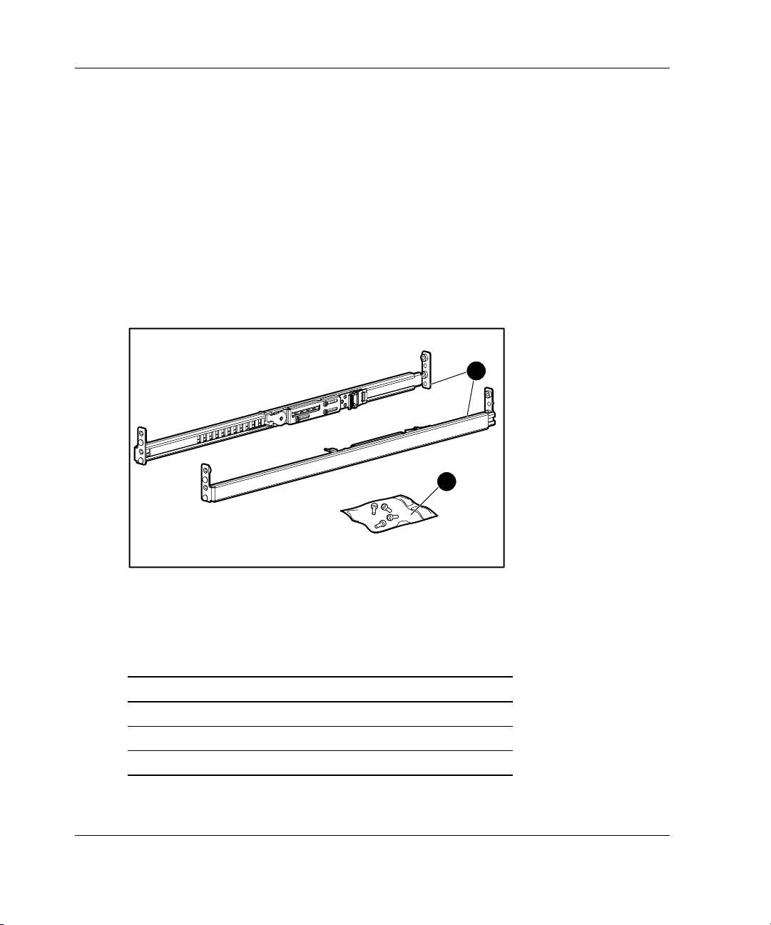
Rack Mounting Hardware
Figure 2-1 and Table 2-1 show the standard rack mounting hardware (for HP,
Compaq branded, and third-party racks) that ships with the ProLiant BL e-Class
server blade enclosure. When shipping a server blade enclosure installed in a rack,
secure the enclosure to the rack using the shipping bracket option kit (part number
293119-B21). Refer to the documentation in the option kit for more information.
IMPORTANT: All the rack mounting hardware necessary for installing the ProLiant BL e-Class
server blade enclosure into an HP, Compaq branded, or third-party rack is included with the
enclosure. For telco racks, a separate option kit with telco rack mounting hardware is
available.
1
2
Figure 2-1: ProLiant BL e-Class standard rack mounting
hardware
Table 2-1: ProLiant BL e-Class Standard Rack
Mounting Hardware
Item Description
1 Rack rails (2, left and right)
2 Bag of screws
Not shown Enclosure rack template
2-8 HP ProLiant BL e-Class System Setup and Installation Guide
Page 37
Rack rails have the following features:
•
Adjustable depth of 61 cm to 91 cm (24 in to 36 in)
•
Depth indicator, visible in the middle of the rail
•
“L” and “R” markings to identify left and right rack rails (from the front of the
rack)
Server Blades
Server blades ship in packages of one or ten server blades.
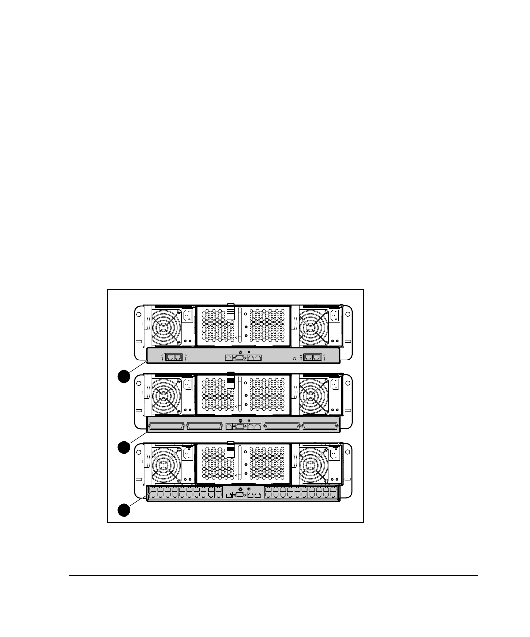
Interconnect Trays
The ProLiant BL e-Class system supports an interconnect tray offered in a choice of
configurations:
Planning the Installation
1
2
3
Figure 2-2: The available interconnect trays
HP ProLiant BL e-Class System Setup and Installation Guide 2-9
Page 38

Planning the Installation
Table 2-2: Interconnect Tray Configurations
Item Description
1 Interconnect switch
2 RJ-21 patch panel
3 RJ-45 patch panel
Optional Installation Service
You may choose to have HP install the ProLiant BL e-Class system. This method
helps ensure top performance from the start. The installation service can be
purchased as an HP Care Pack packaged service or as a customized service
agreement to meet the specific requirements. Some HP Care Pack services are as
follows:
•
HP Care Pack Installation Services for Hardware
HP Care Pack Hardware and Operating System Installation for ProLiant Servers
•
HP Care Pack Installation and Start-up Services for the Microsoft Windows 2000
•
operating system
HP Care Pack Installation and Start-up Services for Insight Manager
•
Visit the HP website for detailed descriptions of these HP Care Pack services.
This optional hardware installation service is available in all countries where HP has
a direct or indirect service presence. Service may be ordered from and directly
provided by an authorized service reseller or, in the United States only, service may
be ordered by calling 1-800-652-6672. In the United States, HP makes all the
arrangements to have the ProLiant BL e-Class system installed by qualified
guaranteed service providers. For ordering information, refer to the HP Care Pack
website:
www.hp.com/services/carepack
2-10 HP ProLiant BL e-Class System Setup and Installation Guide
Page 39

3
Installing and Cabling the System
This chapter contains the following procedures:
•
Installing the interconnect tray in the enclosure
•
Measuring with the rack template
•
Installing the rack rails
•
Installing the enclosure into the rack
•
Cabling the ProLiant BL e-Class system
— Identifying interconnect tray connectors
— Cabling the enclosure
•
Powering up the ProLiant BL e-Class system
•
Powering down the ProLiant BL e-Class system
— Powering down a server blade
— Powering down the enclosure
•
Installing a server blade
•
Removing a server blade
•
Installing additional memory
•
Attaching the diagnostic adapter
HP ProLiant BL e-Class System Setup and Installation Guide 3-1
Page 40
Installing and Cabling the System
Installing the Interconnect Tray
Before installing an interconnect tray into the enclosure, you must first purchase one
as an option. The Integrated Administrator module is included with each interconnect
tray.
NOTE: The installation procedure is the same for any interconnect tray.
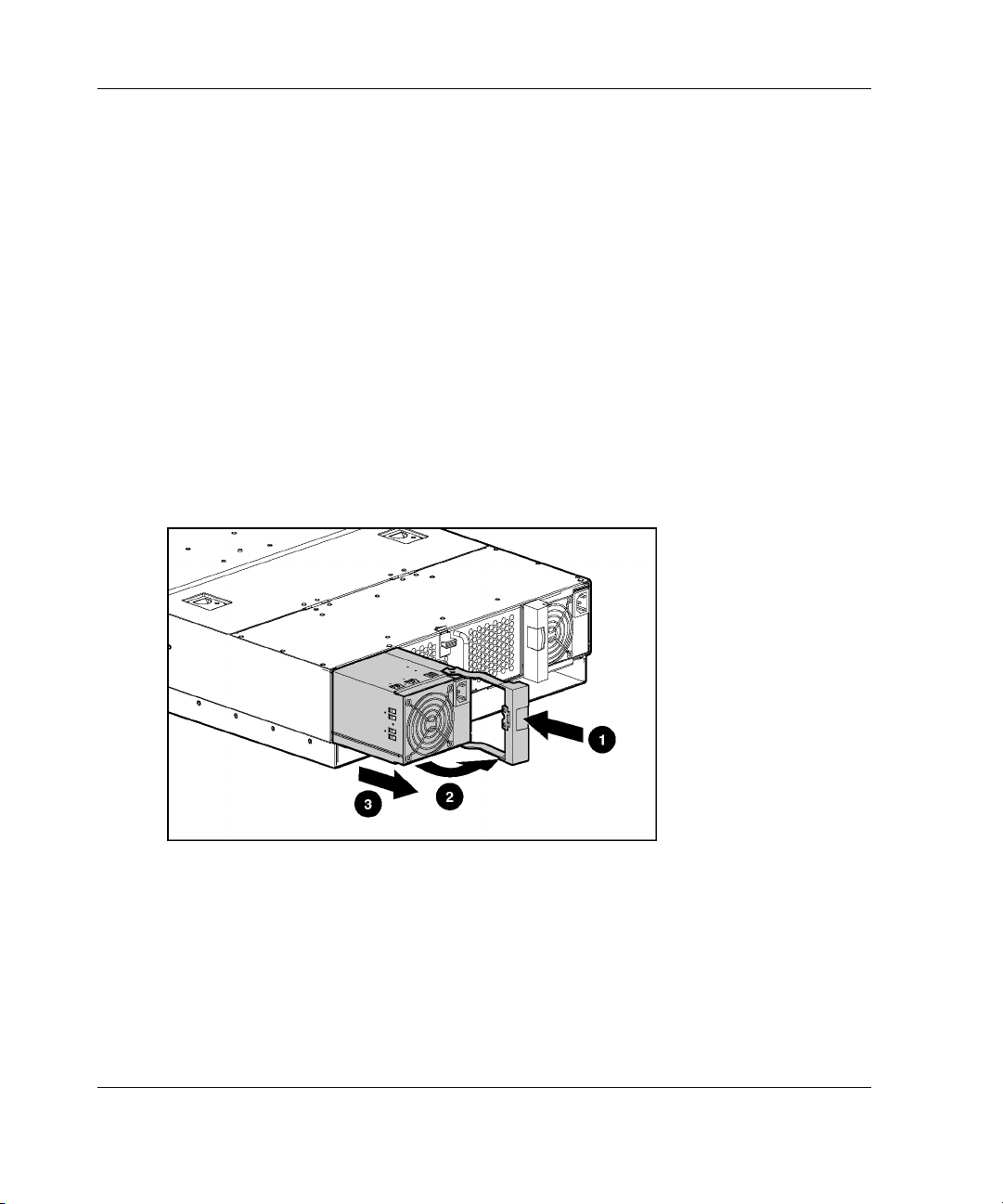
To install the interconnect tray:
1. Press the port-colored latch to release one hot-plug power supply (1).
NOTE: Port-color indicates hot-plug components.
2. Open the handle (2).
3. Slide the hot-plug power supply out of the enclosure (3).
Figure 3-1: Removing a hot-plug power supply
4. Repeat steps 1 through 3 to remove the other hot-plug power supply.
3-2 HP ProLiant BL e-Class System Setup and Installation Guide
Page 41
Installing and Cabling the System
5. Press the interconnect tray release buttons (1).
6. Pull the slate blue ejector levers toward the rear of the enclosure (2).
NOTE: Slate blue indicates internal touch point components.
Figure 3-2: Pulling the interconnect tray ejector levers
HP ProLiant BL e-Class System Setup and Installation Guide 3-3
Page 42

Installing and Cabling the System
7. Insert the interconnect tray into the enclosure (1).
8. Rotate the interconnect tray levers to the locked position (2).
Figure 3-3: Inserting the interconnect tray and engaging
the interconnect tray levers
3-4 HP ProLiant BL e-Class System Setup and Installation Guide
Page 43

Installing and Cabling the System
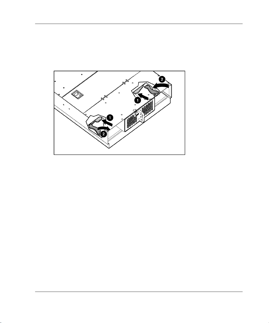
9. Install the hot-plug power supplies (1).
10. Close the power supply handles (2).
Figure 3-4: Installing a hot-plug power supply
HP ProLiant BL e-Class System Setup and Installation Guide 3-5
Page 44

Installing and Cabling the System
Measuring with the Rack Template
Using the rack template, identify the proper holes for inserting the tabs on the vertical
rack supports. Use a pencil to mark the top and bottom edges for the rack supports on
the rack template, which identify the position for the rails supporting the enclosure.
To use the rack template to identify the required space and location for the enclosure:
1. Stand at the front of the rack and identify the front side of the rack template.
2. Starting at the top of the last item installed, secure the rack template against the
front of the rack by sliding the two push tabs into the holes in the rack supports.
WARNING: Racks must be adequately stabilized before and after product
installation. If you are installing an enclosure into an empty rack, you must
install the enclosure at the bottom of the rack and work your way up with
additional enclosures as needed.
IMPORTANT: Match the hole pattern on the rack template with the holes in the rack
supports.
Figure 3-5: Measuring with the ProLiant BL e-Class rack
template
3-6 HP ProLiant BL e-Class System Setup and Installation Guide
Page 45

Installing and Cabling the System
3. Align the rack template so that its sides are square with the sides of the rack.
IMPORTANT: Tick marks on the rack supports help you to maintain proper alignment of
the rack template.
4. Use a pencil to mark an “M” at the locations on the rack where the rack rails are
to be inserted (1).
5. On the rack, mark the top and bottom edges of the rack template to help align the
rack template for the next enclosure (2).
Figure 3-6: Marking the rack for ProLiant BL e-Class
system installation
6. Remove the rack template from the front of the rack and move to the back of the
rack.
7. Identify the back side of the rack template.
8. Repeat steps 2 through 5 for the back of the rack.
NOTE: Store the rack template for future use.
HP ProLiant BL e-Class System Setup and Installation Guide 3-7
Page 46

Installing and Cabling the System
Installing the Rack Rails
1. Measure the depth of the rack.
2. Be sure that the rail locking gear is in the unlocked position (1).
3. Press the rail locking tab to unlock the rack rail (2).
4. Adjust the rack rail to the depth of the rack using the numbers on the rack rail as
a guide (3). The depth of a Compaq branded rack (29 in) is clearly indicated on
the rack rails.
2
3
1
29
Figure 3-7: Unlocking and adjusting a rack rail
IMPORTANT: Numbers on the rack rail provide a gross adjustment of the depth of the
rack. The rack rail may need to be tightened to ensure proper fit.
3-8 HP ProLiant BL e-Class System Setup and Installation Guide
Page 47

Installing and Cabling the System
5. Insert the rear of the right rack rail into the rack at the marks you made when
measuring with the template.
NOTE: The rack rails feature “L” and “R” markings to identify the left and right rack rails
(from the front of the rack).
Figure 3-8: Inserting the rear of the rack rail
HP ProLiant BL e-Class System Setup and Installation Guide 3-9
Page 48
Installing and Cabling the System
6. Compress the spring-loaded rack rail toward the rear of the rack (1).
7. Using the marks you made when measuring with the template, align the front of
the right rail with the holes and release the rail, allowing it to lock into
position (2).
8. Engage the locking gear (3).
2
1
3
Figure 3-9: Inserting the front of the rack rail and
engaging the locking gear
CAUTION: Rack rails must be installed as tightly as possible. Failure to obtain a
correct fit may result in damage to equipment.
Once the right rack rail is properly installed, begin installation of the left rack rail.
3-10 HP ProLiant BL e-Class System Setup and Installation Guide
Page 49
Installing and Cabling the System
Installing the Enclosure into the Rack
WARNING: Remove the two hot-plug power supplies before installing the
enclosure into the rack to reduce weight.
WARNING: At least two people must lift the enclosure into the rack together. If
the enclosure is loaded into the rack above chest level, a third person MUST
assist with aligning the enclosure with the rails while the other two people
support the weight of the enclosure.
CAUTION: Do not remove the enclosure from the rack by the thumbscrews.
Use the handles located above the thumbscrews.
To load the enclosure into the rack:
1. Install the interconnect tray. See the “Installing the Interconnect Tray” section in
this chapter.
2. Stand at the front of the rack.
3. Align the bottom of the enclosure with the top of the rack rails.
HP ProLiant BL e-Class System Setup and Installation Guide 3-11
Page 50
Installing and Cabling the System
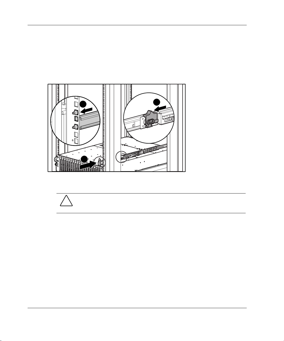
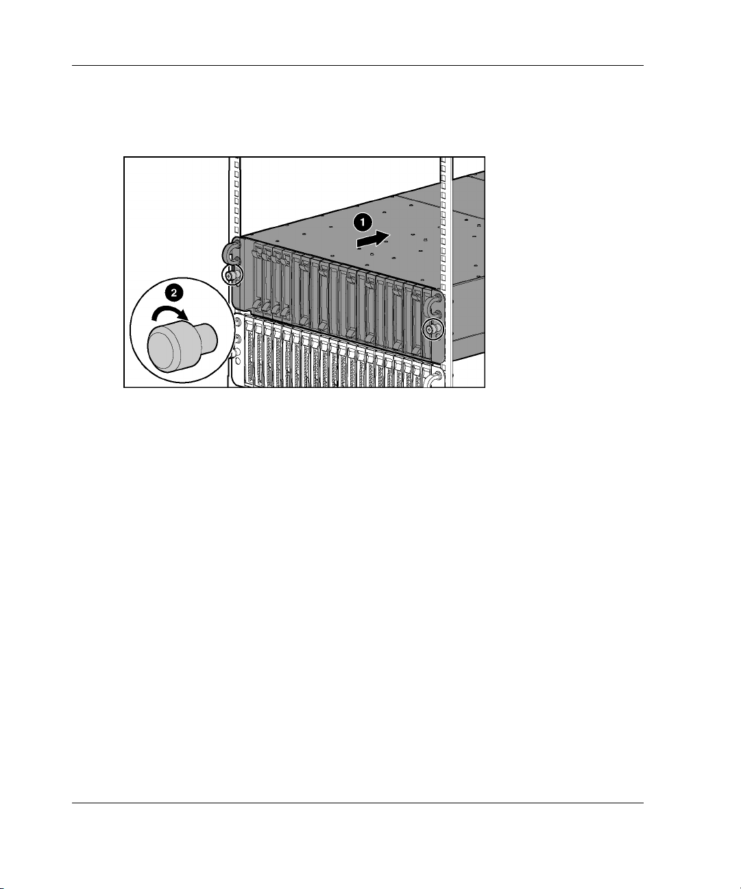
4. Slide the enclosure fully into the rack (1).
5. Tighten the thumbscrews to secure the enclosure in the rack (2).
Figure 3-10: Installing the enclosure into the rack
The enclosure ships with two different sizes of thumbscrews:
• • Size 10-32 thumbscrews with white hexagonal washers, which are compatible
with Compaq branded racks and some HP and third-party racks
Size M6 thumbscrews with black hexagonal washers, which are compatible with
some third-party racks that require metric sizes
3-12 HP ProLiant BL e-Class System Setup and Installation Guide
Page 51
Installing and Cabling the System
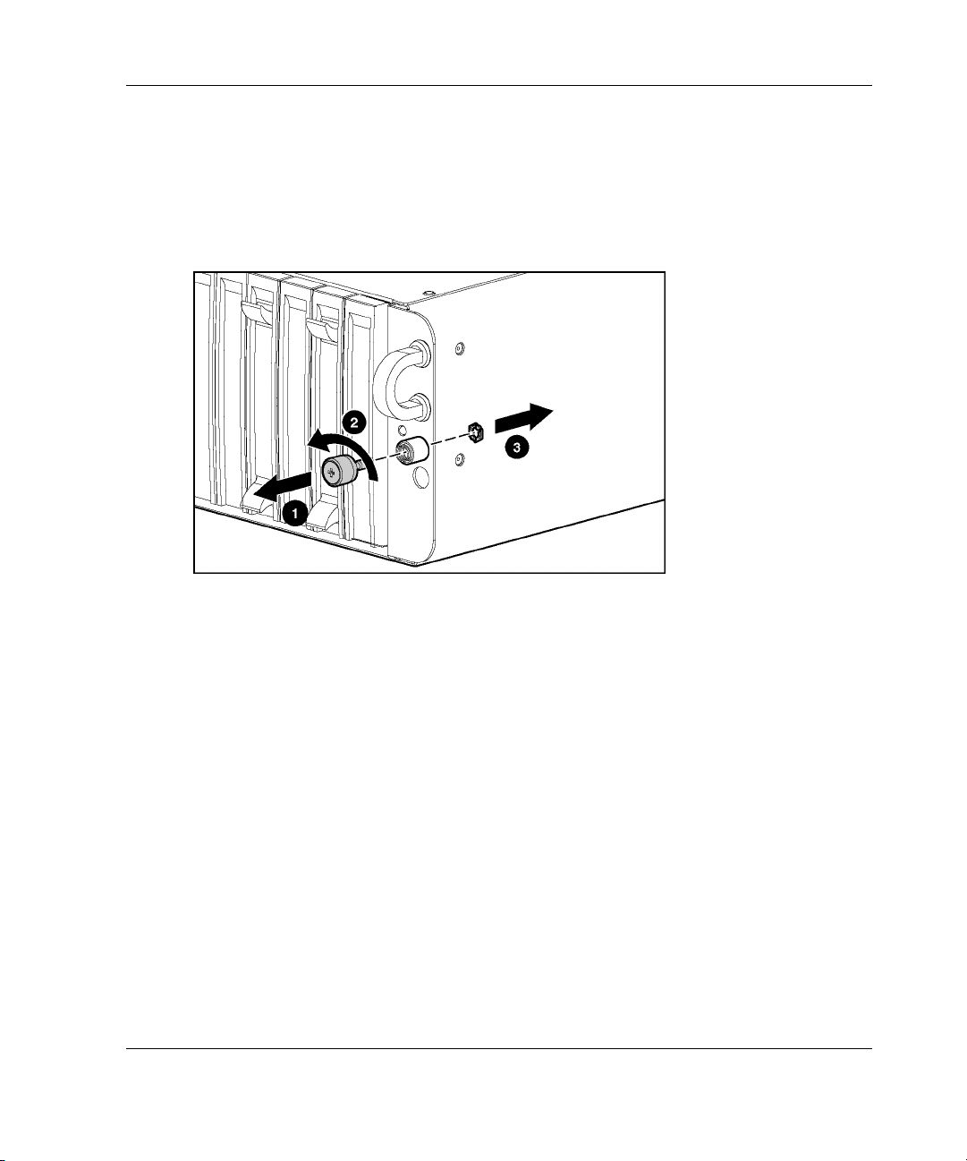
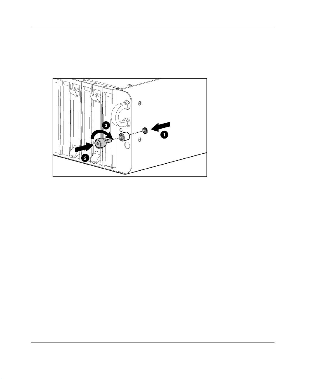
To replace a thumbscrew:
1. Pull the thumbscrew outward while unscrewing the head of the screw (1).
2. Remove the head of the screw (2).
3. Remove the hexagonal washer (3).
Figure 3-11: Removing a thumbscrew and hexagonal
washer
HP ProLiant BL e-Class System Setup and Installation Guide 3-13
Page 52
Installing and Cabling the System
4. Place the hexagonal washer at the back of the hole in the enclosure (1).
5. Insert the screw through the hole in the enclosure (2).
6. Press the head of the screw inward while compressing the spring completely (3).
Figure 3-12: Replacing a thumbscrew, spring, and
hexagonal washer
7. Screw the hexagonal washer onto the shaft of the screw until it passes all the
threads and is secure within the thumbscrew housing.
8. Repeat steps 1 through 7 for the other thumbscrew.
Cabling the ProLiant BL e-Class System
ProLiant BL e-Class systems require no internal cabling. External cabling depends on
the type of interconnect tray installed in the system.
The procedure for cabling an enclosure consists of the following steps:
• • Identifying the interconnect tray connectors
Cabling the server blade enclosure
3-14 HP ProLiant BL e-Class System Setup and Installation Guide
Page 53

Installing and Cabling the System
Identifying Interconnect Tray Connectors
The ProLiant BL e-Class system has several interconnect tray options:
•
ProLiant BL e-Class C-GbE Interconnect Switch with four Gigabit Ethernet
uplink connectors for network cable reduction
•
RJ-21 patch panel with four RJ-21 connectors for network cable consolidation
•
RJ-45 patch panel with 40 RJ-45 connectors
NOTE: An Integrated Administrator module is included with each interconnect tray you
purchase.
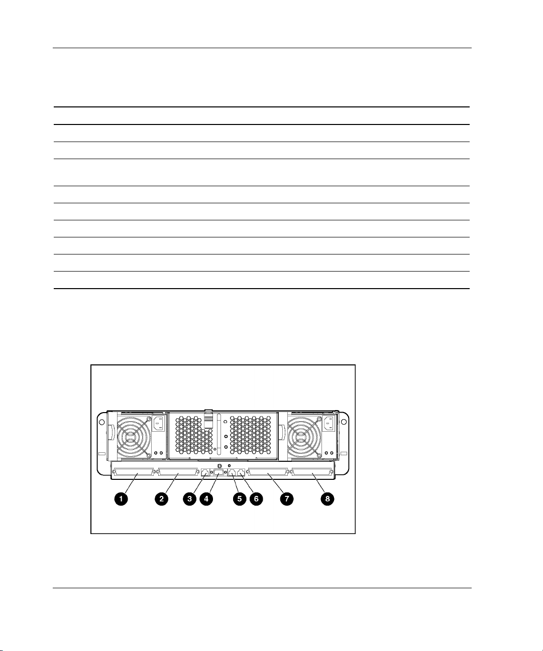
ProLiant BL e-Class C-GbE Interconnect Switch Connectors
The interconnect switch reduces 40 10/100 Ethernet networking connections coming
from the server blades to four Gigabit Ethernet uplink RJ-45 connectors.
Figure 3-13: Interconnect switch connectors
HP ProLiant BL e-Class System Setup and Installation Guide 3-15
Page 54
Installing and Cabling the System
Table 3-1: Interconnect Switch Connectors
Item Description Location
1 Gigabit Ethernet port 26 connector on switch B Interconnect switch
2 Gigabit Ethernet port 25 connector on switch B Interconnect switch
3 Integrated Administrator management connector
(10/100 Ethernet)*
4 Integrated Administrator console connector (serial)* Integrated Administrator module
5 Enclosure link (RJ-45) connector—Reserved* Integrated Administrator module
6 Enclosure link (RJ-45) connector—Reserved* Integrated Administrator module
7 Gigabit Ethernet port 26 connector on switch A Interconnect switch
8 Gigabit Ethernet port 25 connector on switch A Interconnect switch
* These items denote connectors for the Integrated Administrator module.
Integrated Administrator module
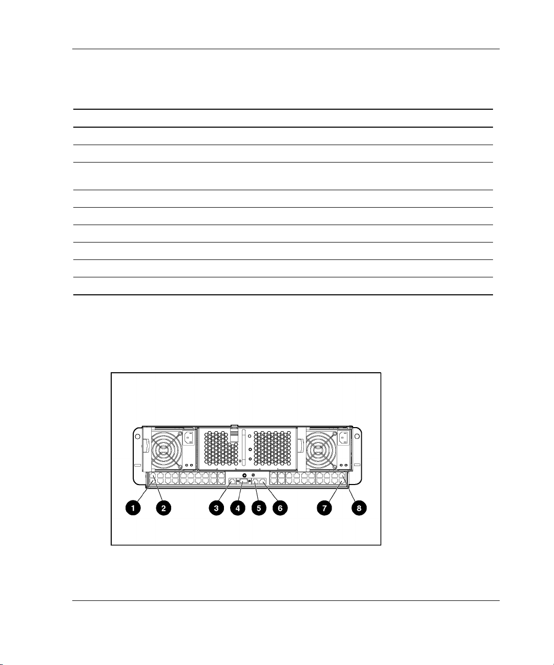
RJ-21 Patch Panel Connectors
The RJ-21 patch panel features a simplified connector configuration that consolidates
the server blade network connections into four RJ-21 connectors.
Figure 3-14: RJ-21 patch panel connectors
3-16 HP ProLiant BL e-Class System Setup and Installation Guide
Page 55
Installing and Cabling the System
Table 3-2: RJ-21 Patch Panel Connectors
Item Description Location
1 RJ-21 connector for server blade bays 11-20 NIC 2 RJ-21 patch panel
2 RJ-21 connector for server blade bays 1-10 NIC 2 RJ-21 patch panel
3 Integrated Administrator management connector
(10/100 Ethernet)*
4 Integrated Administrator console connector (serial)* Integrated Administrator module
5 Enclosure link (RJ-45) connector—Reserved* Integrated Administrator module
6 Enclosure link (RJ-45) connector—Reserved* Integrated Administrator module
7 RJ-21 connector for server blade bays 11-20 NIC 1 RJ-21 patch panel
8 RJ-21 connector for server blade bays 1-10 NIC 1 RJ-21 patch panel
* These items denote connectors for the Integrated Administrator module.
Integrated Administrator module
RJ-45 Patch Panel Connectors
The RJ-45 patch panel features two RJ-45 connectors for each server blade, for a
total of 40 RJ-45 connectors.
Figure 3-15: RJ-45 patch panel connectors
HP ProLiant BL e-Class System Setup and Installation Guide 3-17
Page 56

Installing and Cabling the System
Table 3-3: RJ-45 Patch Panel Connectors
Item Description Location
1 RJ-45 connector for server blade bay 20 NIC 1 RJ-45 patch panel
2 RJ-45 connector for server blade bay 20 NIC 2 RJ-45 patch panel
3 Integrated Administrator management connector
(10/100 Ethernet)*
4 Integrated Administrator console connector (serial)* Integrated Administrator module
5 Enclosure link (RJ-45) connector—Reserved* Integrated Administrator module
6 Enclosure link (RJ-45) connector—Reserved* Integrated Administrator module
7 RJ-45 connector for server blade bay 1 NIC 1 RJ-45 patch panel
8 RJ-45 connector for server blade bay 1 NIC 2 RJ-45 patch panel
* These items denote connectors for the Integrated Administrator module.
Integrated Administrator module
Cabling the Enclosure
To cable a ProLiant BL e-Class server blade enclosure already installed in a rack:
CAUTION: Do not connect external devices to the enclosure link (RJ-45)
connectors unless the device is listed as a supported device on the server
Quickspecs. Connecting an unsupported external device to the enclosure link
(RJ-45) connectors may damage the external device. Refer to the “Identifying
Interconnect Tray Connectors” section of this chapter to locate the enclosure link
(RJ-45) connectors.
1. For accessing and configuring the Integrated Administrator locally, connect a
client device (running VT-100 terminal emulation software) to the Integrated
Administrator console connector using a null-modem cable (provided with the
enclosure). For accessing and configuring the Integrated Administrator over the
network, connect the Integrated Administrator to the management network using
the management connector.
3-18 HP ProLiant BL e-Class System Setup and Installation Guide
Page 57

Installing and Cabling the System
2. Connect the server blade network connectors to the network:
— For the interconnect switch, be sure that at least one of the uplink connectors
is cabled. Any server blade NIC can be routed to any uplink connector.
However, because NIC 1 is PXE-enabled by default on each server blade, it
is recommended that either port 25 or 26 of switch A be used for PXE
functions.
— For the RJ-21 patch panel, be sure that cables for both NIC 1 and NIC 2 are
connected for each group of ten server blades you intend to install in the
enclosure. The two NIC 1 RJ-21 connectors provide PXE connectivity by
default to each group of ten server blades.
— For the RJ-45 patch panel, be sure that cables are connected for each server
blade you intend to install in the enclosure. The NIC 1 RJ-45 connector for
each server blade provides PXE-enabled connectivity by default.
3. Connect an AC power cord to each hot-plug power supply. Note that the
enclosure will power up as soon as an AC power cord is connected to a power
source and a power supply.
HP ProLiant BL e-Class System Setup and Installation Guide 3-19
Page 58

Installing and Cabling the System
4. Bundle network and power cables together and route them to the outer edge of
the rack.
Figure 3-16: Cabling the system with the interconnect
switch
3-20 HP ProLiant BL e-Class System Setup and Installation Guide
Page 59
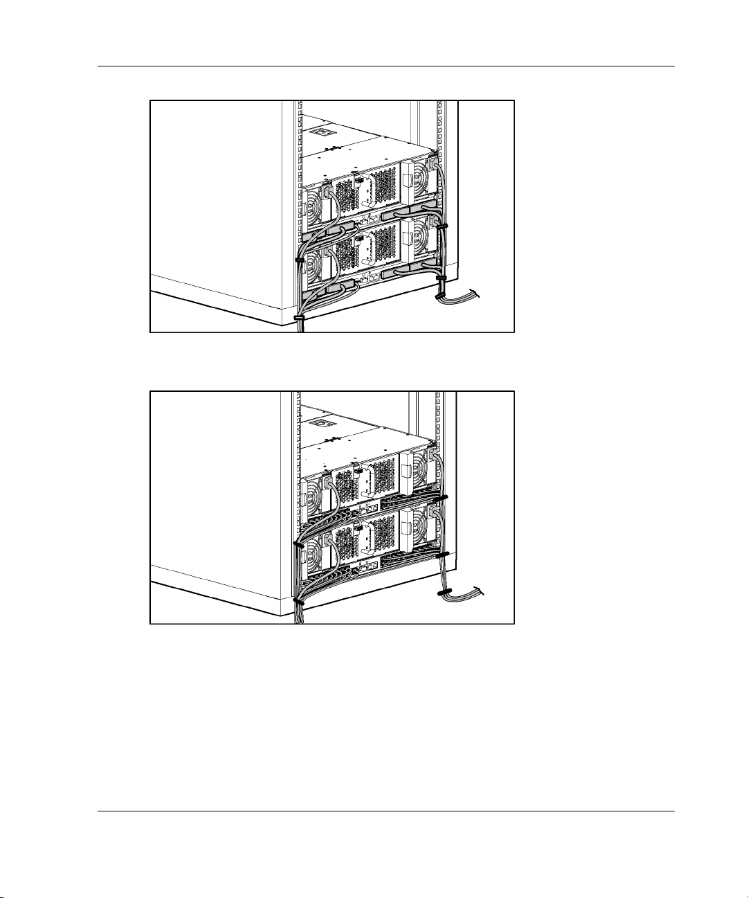
Installing and Cabling the System
Figure 3-17: Cabling the system with the RJ-21 patch
panel
Figure 3-18: Cabling the system with the RJ-45 patch
panel
IMPORTANT: Be sure to route the cables for the enclosure in a manner that provides rapid,
easy access to the console connector for a local client device, such as a laptop computer.
5. Repeat steps 1 through 4 for each server blade enclosure you have installed.
HP ProLiant BL e-Class System Setup and Installation Guide 3-21
Page 60

Installing and Cabling the System
RJ-21 to RJ-45 Cable Kit (Option)
HP offers a set of four cables (257076-B21), each of which connects ten RJ-45
connectors to a single RJ-21 connector for use with the RJ-21 patch panel. Use
Table 3-4 to determine the specifications of this cable.
Table 3-4: Cable Pinout (Sample for Server Blades 1 through 10
NIC 1)
Ethernet Connector
No.
Server blade 1 NIC 1 1
Server blade 2 NIC 1 3
Server blade 3 NIC 1 5
Server blade 4 NIC 1 7
Server blade 5 NIC 1 9
Server blade 6 NIC 1 11
Server blade 7 NIC 1 13
Server blade 8 NIC 1 15
Server blade 9 NIC 1 17
Server blade 10 NIC 1 19
21
23
25 ground 50 ground
Connector
Pin No.
2
4
6
8
10
12
14
16
18
20
22
24
Signal Connector
Pin No.
TxD (-)
RxD (-)
TxD (-)
RxD (-)
TxD (-)
RxD (-)
TxD (-)
RxD (-)
TxD (-)
RxD (-)
TxD (-)
RxD (-)
TxD (-)
RxD (-)
TxD (-)
RxD (-)
TxD (-)
RxD (-)
TxD (-)
RxD (-)
NC
NC
NC
NC
26
27
28
29
30
31
32
33
34
35
36
37
38
39
40
41
42
43
44
45
46
47
48
49
Signal
TxD (+)
RxD (+)
TxD (+)
RxD (+)
TxD (+)
RxD (+)
TxD (+)
RxD (+)
TxD (+)
RxD (+)
TxD (+)
RxD (+)
TxD (+)
RxD (+)
TxD (+)
RxD (+)
TxD (+)
RxD (+)
TxD (+)
RxD (+)
NC
NC
NC
NC
3-22 HP ProLiant BL e-Class System Setup and Installation Guide
Page 61

Null-Modem Cable
If you are cabling a serial device such as a laptop computer to the console connector
on the Integrated Administrator, be sure that you use the null-modem cable provided
with the enclosure and not a straight-through cable. Use Table 3-5 to determine the
specifications of this cable.
Table 3-5: Cable Pinout for a Null-Modem Cable
Installing and Cabling the System
Signal
Name
TxD 3 2 3
RxD 2 3 2
RTS 7 8 5
CTS 8 7 4
GND 5 5 7
DSR 6 4 20
CD 1 4 20
DTR 4 1 & 6 6 & 8
TxD 3 2 3
EM PIN DB-9 PIN DB-25 PIN
Powering Up the ProLiant BL e-Class System
As soon as you connect an AC power cord to a hot-plug power supply on the rear
panel, the enclosure powers up. Plug in the second power supply for redundancy.
As soon as you remove a server blade blank and install a server blade into the front
panel of the enclosure, the server blade powers up.
Powering Down the ProLiant BL e-Class System
You can power down one or more server blades or the entire enclosure.
HP ProLiant BL e-Class System Setup and Installation Guide 3-23
Page 62

Installing and Cabling the System
Powering Down a Server Blade
To power down a server blade:
1. Be sure that the server blade is not active.
For specific information about server blade LEDs, see Table E-5 in Appendix E,
“LEDs and Switches.”
2. If the server blade is active, notify users and stop applications as necessary.
3. Shut down the operating system. This may shut off the server blade power.
4. If the server blade still has power, power down the server blade by either:
— Using the Integrated Administrator
or
— Pressing the power button on the front of the server blade
IMPORTANT: Refer to the HP ProLiant BL e-Class Integrated Administrator User Guide
to power down the server blade using the Integrated Administrator.
Figure 3-19: Powering down the server blade
3-24 HP ProLiant BL e-Class System Setup and Installation Guide
Page 63

To perform an emergency shut down of a server blade, press and hold the blade
power button for 4 seconds.
CAUTION: Performing an emergency shutdown on a server blade may result in the
loss of any unsaved data.
Powering Down the Enclosure
To perform a graceful shutdown of the enclosure and all the server blades, press the
enclosure power button. If the operating system is Microsoft® Windows® 2000, the
enclosure automatically performs a graceful shutdown of all server blades, and then
removes power from the enclosure. If the operating system is Red Hat Linux, you
must have the Linux Health driver installed in order for the server blades to shutdown
gracefully.
To perform an emergency shut down of the enclosure and all server blades, press and
hold the enclosure power button for 4 seconds.
CAUTION: Performing an emergency shutdown on the enclosure may result in the
loss of any unsaved data on all server blades.
Installing and Cabling the System
Installing a Server Blade
CAUTION: Electrostatic discharge can damage electronic components. Properly
ground yourself before beginning any installation procedure. See Appendix B,
“Electrostatic Discharge,” for more information.
To install a server blade:
1. Determine the hardware configuration and server deployment process. See
Chapter 4, “Deployment and Management.”
2. Install or upgrade memory before installing server blades into an enclosure. See
the “Installing Additional Memory” section in this chapter.
HP ProLiant BL e-Class System Setup and Installation Guide 3-25
Page 64
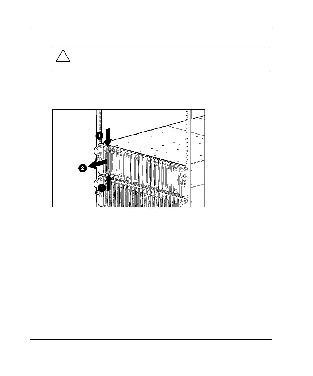
Installing and Cabling the System
CAUTION: Always populate the server blade bays with either a server blade or
server blade blank. Proper airflow can only be maintained when the bays are
populated. Unpopulated bays can lead to improper cooling and thermal damage.
3. Remove the server blade blank:
a. Press the ejector tabs on the server blade blank (1).
b. Slide the server blade blank out of the bay (2).
Figure 3-20: Removing a single-bay server blade blank
3-26 HP ProLiant BL e-Class System Setup and Installation Guide
Page 65

Installing and Cabling the System
Figure 3-21: Removing a five-bay server blade blank
NOTE: Store the server blade blank for future use.
4. Install the server blade:
IMPORTANT: Before installing server blades for the first time, define the hardware
configuration and server deployment process. See Chapter 4, “Deployment and Management.”
a. Align the server blade with the server blade bay on the enclosure.
CAUTION: The server blade is keyed to fit only one way in the bay. If the server
blade does not slide easily into the bay, be sure that the server blade is oriented
correctly.
HP ProLiant BL e-Class System Setup and Installation Guide 3-27
Page 66
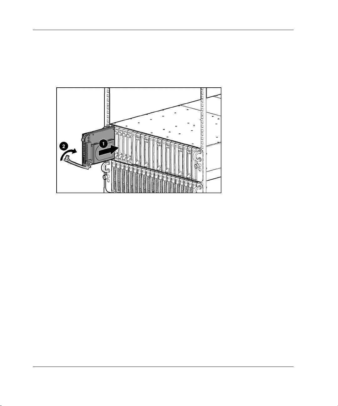
Installing and Cabling the System
b. Slide the server blade inward until the ejector lever engages the enclosure
(1).
c. Close the ejector lever until you hear an audible click that indicates the server
blade is properly seated (2).
Figure 3-22: Installing a server blade
IMPORTANT Install a server blade for each of the blanks you have removed.
Repeat steps 2 to 4 for each server blade you wish to install.
3-28 HP ProLiant BL e-Class System Setup and Installation Guide
Page 67
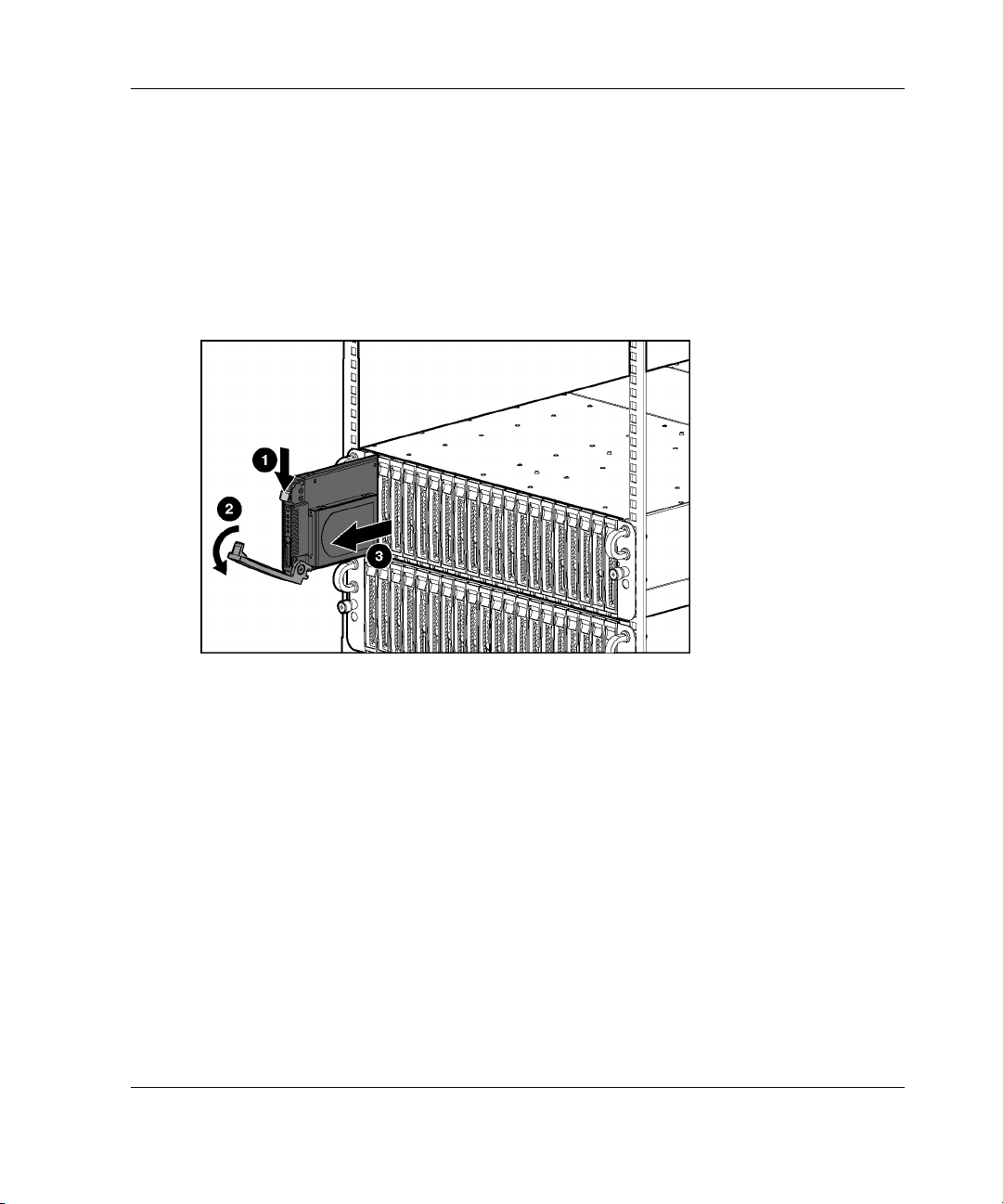
Removing a Server Blade
To remove a server blade:
1. Press the release latch (1).
2. Pull down the ejector lever (2).
3. Remove the server blade from the enclosure (3).
Installing and Cabling the System
Figure 3-23: Removing a server blade
HP ProLiant BL e-Class System Setup and Installation Guide 3-29
Page 68

Installing and Cabling the System
Installing Additional Memory
The server blades support the following memory features:
• • Registered SDRAM memory for the ProLiant BL10e server blade; Registered
DDR SDRAM memory for the ProLiant BL10e G2 server blade
For more information, refer to QuickSpecs located on the HP website:
www.hp.com
ECC memory
— Detects and corrects single-bit memory errors
— Detects multi-bit memory errors
To install DIMMs on a server blade:
1. Power down the server blade. See the “Powering Down a Server Blade” section
in this chapter.
2. Remove the server blade from the enclosure. See the “Removing a Server Blade”
section in this chapter.
3. Place the server blade on a level, nonconductive surface.
3-30 HP ProLiant BL e-Class System Setup and Installation Guide
Page 69
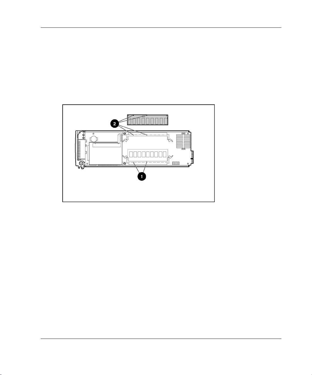
Installing and Cabling the System
4. Locate the DIMM socket keys on the server blade:
— DIMM socket 1 keys (1)
— DIMM socket 2 keys (2)
IMPORTANT: DIMMs on a ProLiant BL10e server blade are installed inverted from one
another. If the labels on DIMM 1 are face-up, the labels on DIMM 2 are probably facedown.
Figure 3-24: ProLiant BL10e server blade DIMM socket
keys
HP ProLiant BL e-Class System Setup and Installation Guide 3-31
Page 70
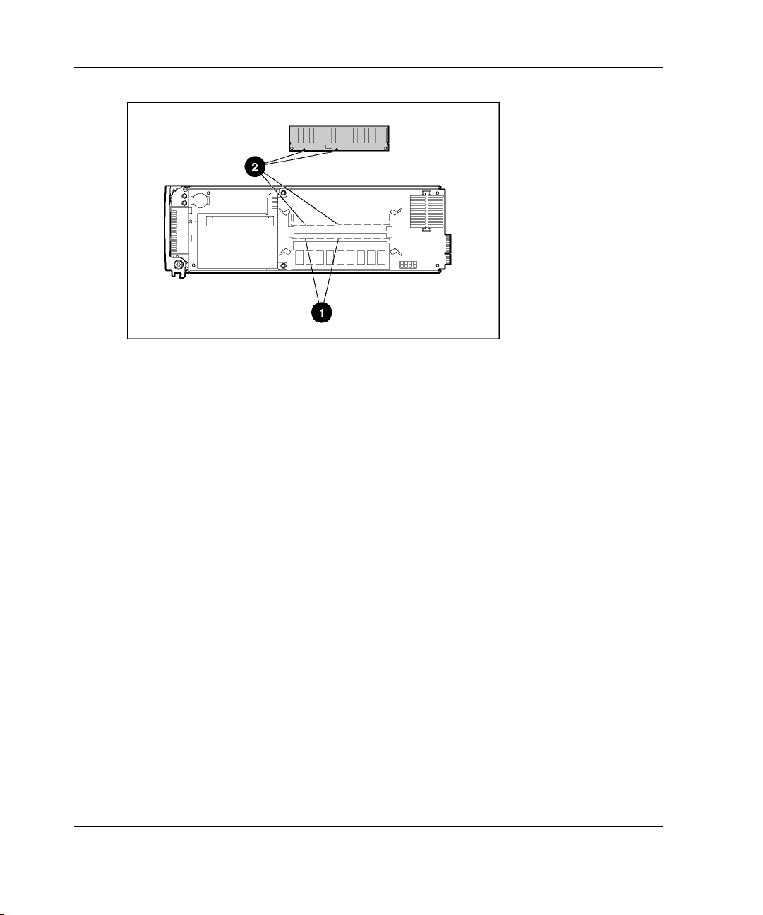
Installing and Cabling the System
Figure 3-25: ProLiant BL10e G2 server blade DIMM
socket keys
IMPORTANT: Each server blade ships with one DIMM installed.
3-32 HP ProLiant BL e-Class System Setup and Installation Guide
Page 71
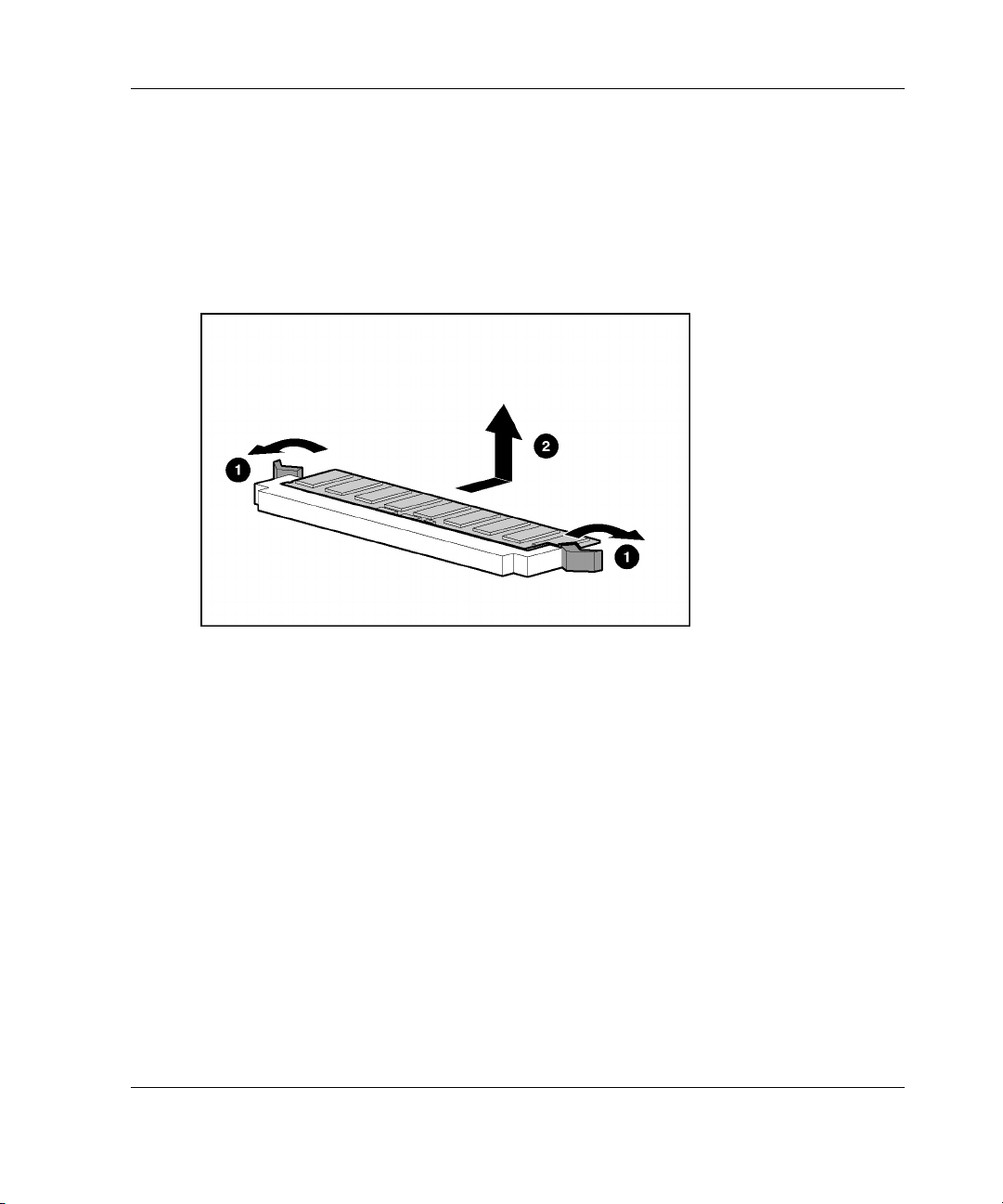
Installing and Cabling the System
IMPORTANT: Step 5 applies only when you wish to upgrade DIMMs.
5. Remove the existing DIMM:
a. Release the latches on each side of the DIMM slot 1 (1).
b. Remove the DIMM from the server blade (2).
Figure 3-26: Removing a DIMM
HP ProLiant BL e-Class System Setup and Installation Guide 3-33
Page 72
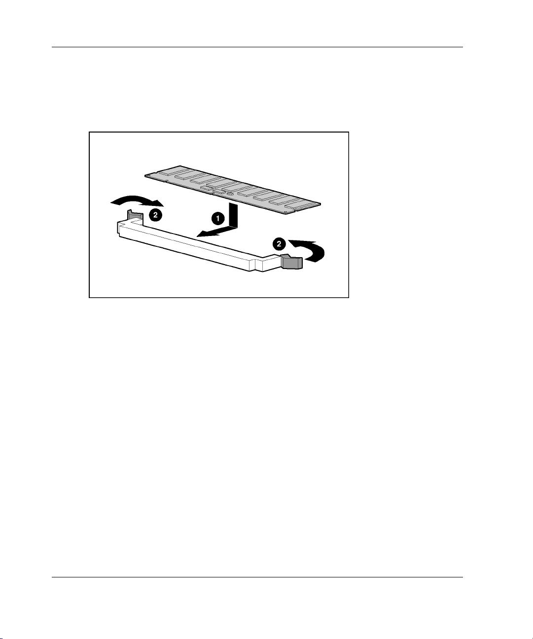
Installing and Cabling the System
6. Install DIMM 1:
a. Insert the DIMM into the DIMM slot (1) until the latches snap into place.
b. Press the latches towards each other to ensure that they are fully seated (2).
Figure 3-27: Installing a DIMM
7. Repeat step 6 to install a second DIMM into DIMM slot 2.
3-34 HP ProLiant BL e-Class System Setup and Installation Guide
Page 73
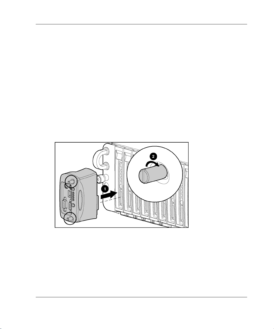
Attaching the Diagnostic Adapter
Attach the diagnostic adapter to the diagnostic connector on the front of the server
blade in order to attach peripherals such as a keyboard, video, mouse, USB diskette
drive, or USB CD-ROM drive.
IMPORTANT: You can hot-add peripheral devices using the diagnostic adapter if the devices
support hot-plug capability.
To install the diagnostic adapter:
1. Power down the server blade. See the “Powering Down a Server Blade” section
in this chapter.
2. Insert the diagnostic adapter into the diagnostic connector on the server blade (1).
3. Tighten the thumbscrews securing the diagnostic adapter in place (2).
Installing and Cabling the System
Figure 3-28: Attaching the diagnostic adapter
IMPORTANT: Because PS/2 devices do not support hot-plug technology, restart the server
blade after attaching the diagnostic adapter. USB devices support hot-plug capability and do
not require restarting the server blade after attachment.
HP ProLiant BL e-Class System Setup and Installation Guide 3-35
Page 74

Installing and Cabling the System
Use Figure 3-29 and Table 3-6 to identify connectors on the diagnostic adapter.
Figure 3-29: Connectors on the diagnostic adapter
Table 3-6: Connectors on the Diagnostic Adapter
Item Description
1 Keyboard connector
2 Mouse connector
3 USB 2
4 USB 1
5 Serial connector
6 Video connector
3-36 HP ProLiant BL e-Class System Setup and Installation Guide
Page 75

4
Deployment and Management
This chapter provides the following information:
• • An overview of available methods for deploying software on ProLiant BL
e-Class server blades
— Automated deployment using HP ProLiant Essentials Rapid Deployment
Pack
— Alternate deployment methods
— Diagnostic adapter
A description of the configuration software and utilities supported by the
ProLiant BL e-Class system
— Supported operating systems
— ROM-Based Setup Utility (RBSU)
— Redundant ROM support
— ROMPaq Utility
— Remote ROM Flash
— ProLiant BL e-Class Integrated Administrator
— Insight Manager 7
— ProLiant BL e-Class C-GbE Interconnect Switch (option) management tools
and utilities
HP ProLiant BL e-Class System Setup and Installation Guide 4-1
Page 76

Deployment and Management
ProLiant BL e-Class Server Blade Deployment Options
The ProLiant BL e-Class server blades are designed for rapid deployment and are
ideally suited for headless (unattended), network-based software installation and
configuration. Rapid Deployment Pack is the optimum choice for ProLiant BL
e-Class server blades and facilitates the configuration of a few or hundreds of servers
from an easy-to-use, remote-based graphical deployment console. The PXE-enabled
NICs and support for a bootable USB diskette drive on the ProLiant BL e-Class
server blade also facilitate the use of other deployment methods.
Automated Deployment Using HP ProLiant Essentials
Rapid Deployment Pack
Rapid Deployment Pack integrates two powerful products: Altiris eXpress
Deployment Solution and the ProLiant Integration Module. The Deployment Server
Console contains optimizations for ProLiant servers. It provides intuitive deployment
jobs to deploy the standard hardware and operating system configurations and
applications on any combination of server blades using both scripting and imaging,
and then simultaneously deploys multiple server blades. Rapid Deployment Pack also
has advanced features that can detect and display server blades based on their
physical rack, enclosure, and bay locations. You can set the Deployment Server
Console to automatically install pre-defined configurations on newly installed server
blades.
For more information about Rapid Deployment Pack, refer to an authorized reseller,
the Rapid Deployment Pack CD that ships with the enclosure, or visit the following
website:
www.hp.com/servers/rdp
4-2 HP ProLiant BL e-Class System Setup and Installation Guide
Page 77

Alternate Deployment Methods
ProLiant BL e-Class server blades have PXE-enabled NICs and support a bootable
USB diskette drive, as well as keyboard, video, mouse, and USB CD-ROM drive
attached using the diagnostic adapter. These features enable you to use your own
network-based or local, attended deployment methods for booting and installing
software onto ProLiant BL e-Class server blades.
To install operating systems onto the ProLiant BL e-Class server blades with a PXE
server and a DHCP server, the PXE server must be connected to NIC 1 of each server
blade you wish to deploy. NIC 1 is PXE-enabled by default.
IMPORTANT: ProLiant BL e-Class server blades do not support a bootable CD-ROM. You
MUST create a bootable diskette in order to boot the system using this deployment method.
For detailed instructions on network-based PXE installation for Red Hat Linux, refer
to the white papers located on the following website:
ftp://ftp.compaq.com/pub/supportinformation/papers/163e-0102awwen_rev0_us.pdf
To install Windows 2000 using PXE, you must use Rapid Deployment Pack (which
includes pre-written scripts to install Windows 2000 Server on the server blades) or
an alternate method.
Deployment and Management
If you prefer an unattended (headless) installation of the operating systems and do not
wish to use Rapid Deployment Pack, you can download the SmartStart Scripting
Toolkit from the following website:
www.hp.com/servers/sstoolkit
If you would like to use Insight Manager 7, copy the management agents for the
ProLiant BL e-Class server blades from the Rapid Deployment Pack CD or download
them from the following website:
http://h18000.www1.hp.com/products/servers/management/agents.html
IMPORTANT: Use the Management CD to install Insight Manager 7.
HP ProLiant BL e-Class System Setup and Installation Guide 4-3
Page 78

Deployment and Management
Diagnostic Adapter
The diagnostic adapter enables local health monitoring and management by enabling
you to attach peripheral devices directly to a server blade. Using the diagnostic
adapter, you can:
•
View server blade event messages (See the “Server Blade Event Messages”
section in this chapter.)
•
Flash the server blade ROM (See the “Flashing the Server Blade ROM” section
in this chapter.)
•
View software information during deployment
For instructions on how to attach the diagnostic adapter, see Chapter 3, “Installing
and Cabling the System.”
IMPORTANT: You can hot-add peripheral devices using the diagnostic adapter if the devices
support hot-plug capability.
ProLiant BL e-Class Server Blade Supported Software Utilities
Configuring the server blades includes installing an operating system, applications,
and optimized drivers.
Rapid Deployment Pack enables you to auto-detect and configure the server
hardware and to install optimized drivers.
Supported Operating Systems
For the most current information about operating system support on ProLiant BL
e-Class server blades, refer to the operating system support matrix available at the
following website:
ftp://ftp.compaq.com/pub/products/servers/os-support-matrix-310.pdf
4-4 HP ProLiant BL e-Class System Setup and Installation Guide
Page 79

ROM-Based Setup Utility
ROM-Based Setup Utility (RBSU) performs configuration activities and enables you
to view server blade configuration information. The server blades come pre-
configured and do not require interaction with RBSU, unless you would like to
change the default settings. The following table contains the default settings for
options in primary RBSU menus.
Table 4-1: ROM-Based Setup Utility Default Settings
Menu/Option Default Setting
System Options
Serial Number
Embedded NIC 1 PXE Support Enabled
Embedded NIC 2 PXE Support Disabled
IPL Device Boot Order
IPL Device Boot Order *
Boot Controller Order
Automatic Server Recovery
Automatic Server Recovery Status Enabled
Automatic Server Recovery Timeout
Thermal Shutdown Enabled
Deployment and Management
Server Passwords
Set Power-On Password Disabled
Set Administrative Password Disabled
*The boot order is CD-ROM drive, diskette drive, hard drive,
network. Availability of these devices depends on which ones
are connected to the system.
continued
HP ProLiant BL e-Class System Setup and Installation Guide 4-5
Page 80

Deployment and Management
Table 4-1: ROM-Based Setup Utility Default Settings continued
Menu/Option Default Setting
Server Asset Text
Set Server Info Text Disabled
Set Admin Info Text
Set Server Contact Text
Advanced Options
POST Speed Up Enabled
POST F1 prompt Enabled
Wake on LAN Enabled
ROM selection
Set CPU Corrected
Erase Non-volatile Memory Enabled
Drive Write Cache Disabled
NMI Debug Button Enabled
Custom POST Message
Erase NVRAM/Boot Disk
IMPORTANT: ProLiant BL e-Class server blades do not support a bootable USB CD-ROM
drive.
Redundant ROM Support
ProLiant BL e-Class server blades enable you to upgrade or configure the ROM
safely with redundant ROM support. The server blade has a 2-MB ROM that acts as
two separate 1-MB ROMs. In the standard implementation, one side of the ROM
contains the current ROM program version, while the other side of the ROM contains
a backup version.
When the server blade boots, it identifies whether the current ROM bank is corrupt.
If a corrupt ROM is detected, the server blade boots from the backup ROM and alerts
you through POST or IML that the ROM bank is corrupt.
4-6 HP ProLiant BL e-Class System Setup and Installation Guide
Page 81

Deployment and Management
Two methods allow you to access the redundant ROM:
• • Switching to the backup ROM through RBSU
— Using a monitor and keyboard using the diagnostic adapter
— Using the Integrated Administrator
Manually forcing to the backup ROM through the server blade maintenance
switch (SW1)
Switching to the Backup ROM Through ROM-Based Setup Utility
To access the RBSU using the diagnostic adapter:
1. Install the diagnostic adapter onto the server blade.
2. Install a keyboard, mouse, and monitor onto the diagnostic adapter.
3. Access RBSU by pressing the F9 key during power up when the prompt appears
in the lower right corner of the screen.
4. Click Advanced Options.
5. Click ROM Selection.
6. Click Switch to Backup and press the Enter key.
7. Press the Esc key to exit the current menu or press the F10 key to exit RBSU.
8. Power cycle the server.
For details on accessing RBSU through the Integrated Administrator, refer to the HP
ProLiant BL e-Class Integrated Administrator User Guide on the documentation CD
that ships with the enclosure.
HP ProLiant BL e-Class System Setup and Installation Guide 4-7
Page 82

Deployment and Management
Accessing Redundant ROM Using the Server Blade Maintenance Switch
If the system does not boot, you may access the redundant ROM manually using the
server blade maintenance switch (SW1). To access the redundant ROM using SW1:
1. Power down the server blade. See the “Powering Down a Server Blade” section
in Chapter 3, “Installing and Cabling the System.”
2. Remove the server blade from the enclosure. See the “Removing a Server Blade”
section in Chapter 3, “Installing and Cabling the System.”
3. Set server blade maintenance switches (SW1) 1 and 4 to on. For the location of
these switches, see Appendix E, “LEDs and Switches.”
4. Insert the server blade back in the server blade bay. After the system powers on,
it repeatedly emits two long beeps.
5. Power down the server blade again. If necessary, perform a forced shutdown by
pressing the power button for 4 seconds.
6. Remove the server blade from the enclosure again.
7. Set the server blade maintenance switches (SW1) 1 and 4 back to the default
position (off).
8. Insert the server blade back into the server blade bay.
9. Power up the server blade.
If the system still does not boot, see Appendix D, “Troubleshooting.”
Flashing the Server Blade ROM
When you flash the server blade ROM, ROMPaq writes over the older ROM and
saves the current ROM as a backup, enabling you to switch easily to the backup
ROM version. This feature protects the previous ROM version, even if you
experience a power failure while flashing the ROM.
Two methods are available for flashing the ROM:
• • Upgrading the server blade ROM using ROMPaq Utility
Remote ROM flash
4-8 HP ProLiant BL e-Class System Setup and Installation Guide
Page 83

Upgrading the Server Blade ROM Using ROMPaq Utility
Use server blade ROMPaq utilities to upgrade the firmware (BIOS).
To use the ROMPaq Utility:
1. Download the latest version of the system BIOS for the ProLiant BL e-Class
server blade onto a diskette. The latest system BIOS is available at:
www.hp.com
2. Power down the server blade. See the “Powering Down a Server Blade” section
in Chapter 3, “Installing and Cabling the System.”
3. Remove the server blade. See the “Removing a Server Blade” section in
Chapter 3, “Installing and Cabling the System.”
4. Attach the diagnostic adapter to the server blade.
5. Attach a USB diskette drive, a keyboard, a monitor, and a mouse to the
diagnostic adapter.
6. Insert the diskette into the diskette drive.
7. Install the server blade and flash the ROM. See the “Installing a Server Blade”
section in Chapter 3, “Installing and Cabling the System.”
Deployment and Management
Remote ROM Flash
Using the Smart Components for Remote ROM Flash with the Remote Deployment
Utility (RDU) console application, Remote ROM Flash enables Windows users to
upgrade the firmware (BIOS) on a server from a remote location.
To update the ROM from a remote location, download the Online Flash Utility from
the HP website:
www.hp.com
If a power loss occurs during a firmware upgrade, redundant ROM support enables
data recovery.
HP ProLiant BL e-Class System Setup and Installation Guide 4-9
Page 84

Deployment and Management
ProLiant BL e-Class Integrated Administrator
The ProLiant BL e-Class Integrated Administrator is a centralized management and
monitoring system for the ProLiant BL e-Class enclosure and server blades. The
Integrated Administrator acts as a combination terminal server and remote power
controller, enabling out-of-band, secure, serial console connections to all server
blades in the enclosure, and offers all the following:
•
Full Command Line Interface (CLI) and Web interface
— Server blade privileges can be set on a user basis
— Virtual power button to power server blade on or off
— Ability to generate non-maskable interrupt on the server blade for crash
debug and analysis through the command line interface
— More than 100 scriptable commands to enable automated deployment and
management
•
Remote administration
— Enables access to the serial console for the server blade
— Enables full control over Power-On Self Test (POST) and boot process for
the server blade, including the ROM-Based Setup Utility (RBSU)
— Enables future manageability enhancements with the Online Integrated
Administrator Firmware Update feature
•
Hardware health monitoring
The Integrated Administrator monitors and controls the enclosure fans,
temperature sensors, power supplies, and server blade status.
•
Offline console buffering (when not connected) and event logging
— Operating system console logging
— Server blade and enclosure hardware events
4-10 HP ProLiant BL e-Class System Setup and Installation Guide
Page 85

Deployment and Management
• Security features
— Secure Shell access
— User administration for up to 25 users
— Event generation for invalid login attempts
— Logging of user actions in event log
— Selective enabling of all protocols, such as Telnet
— Out-of-band management using Integrated Administrator’s RS-232 console
— Secure Sockets Layer (SSL) (Web interface)
— Customer installable SSL certificates
• • Increased availability
— The Integrated Administrator is a self-contained embedded system with its
own processor, memory, NIC, and flash ROM.
— The enclosure itself is intelligent and fault-tolerant, and continues to function
even if the Integrated Administrator fails.
— The Integrated Administrator enables online firmware update with code
signing to ensure only certified software releases are installed.
Insight Manager 7 integration
— Insight Manager 7 identifies the Integrated Administrator as a server blade
“management processor.”
— The Integrated Administrator status is part of the server blade status. If the
Integrated Administrator is degraded, all server blades managed by that
Integrated Administrator are shown as degraded.
— Insight Manager 7 can capture the Integrated Administrator SNMP traps.
— Insight Manager 7 and Web agents enable the user to launch the Integrated
Administrator Web interface.
HP ProLiant BL e-Class System Setup and Installation Guide 4-11
Page 86

Deployment and Management
The Integrated Administrator Web interface enables full access and control of the
server blades and enclosure using a browser, including:
•
Enclosure management
— Monitor fans, power supplies, and temperature
— Graceful enclosure and server blade power shutdown
— Enclosure unit identification (UID) control
— Interface to management tools and utilities associated with the optional
interconnect switch
For details on the management tools and utilities associated with the optional
interconnect switch, refer to the HP ProLiant BL e-Class C-GbE
Interconnect Switch User Guide.
•
Server blade management
— Remote power (on/off/reboot) and unit identification (UID) controls
— Remote serial console
— General health status
•
User management
— Add/remove/modify administrators/groups/users
— Allow two levels of user access
For more information, including instructions on flashing the Integrated Administrator
ROM, refer to the HP ProLiant BL e-Class Integrated Administrator User Guide on
the Documentation CD that ships with the server blade enclosure.
4-12 HP ProLiant BL e-Class System Setup and Installation Guide
Page 87

Server Blade Event Messages
The event list displays the affected components and the associated error messages.
Though the same basic information is displayed, the format of the list may differ
depending on whether you view it from within Insight Manager 7 or from within the
Survey Utility.
Table 4-2 identifies the event types (affected components) and associated event
messages.
Table 4-2: Server Blade Event Messages
Event Type Event Message
Deployment and Management
Server Blade Environment
Overheat condition* System Overheating (Zone X)
Main Memory
Correctable error threshold exceeded Corrected Memory Error threshold passed (Slot X,
Corrected Memory Error threshold passed (System
Memory Module X)
Memory)
continued
HP ProLiant BL e-Class System Setup and Installation Guide 4-13
Page 88

Deployment and Management
Table 4-2: Server Blade Event Messages continued
Event Type Event Message
Corrected Memory Error threshold passes (Memory
Module unknown)
Processor
Correctable error threshold exceeded Processor Correctable Error threshold passed
Uncorrectable error Processor Uncorrectable internal error
Automatic Server Recovery
System lockup The Integrated Administrator has issued an alert that its
Operating System
System crash Blue Screen Trap: Cause [all Windows operating systems]
Automatic operating system shutdown Automatic Operating System Shutdown Initiated Due to
health state has changed **
Kernel Panic: Cause [Linux]
Fan Failure
Automatic Operating System Shutdown Initiated Due to
Overheat Condition
Fatal Exception (Number X, Cause)
Enclosure Environment
Overheat Condition The Integrated Administrator has issued an alert that its
Power Supply Failure The Integrated Administrator has issued an alert that its
Fan Failure The Integrated Administrator has issued an alert that its
* For specific operating temperature ranges, see Appendix F, “Specifications.”
** Refer to the Integrated Administrator log for detailed messages.
4-14 HP ProLiant BL e-Class System Setup and Installation Guide
health state has changed **
health state has changed **
health state has changed **
Page 89

Insight Manager 7
IMPORTANT: You can install Insight Manager 7 using the Management CD included with the
enclosure or download it from the HP website.
Insight Manager 7 is a server management tool that provides in-depth fault,
configuration, and performance monitoring of up to hundreds of servers (including
server blades) from a single management console. You can use Insight Manager 7 to
view each server blade and the Integrated Administrator of each server blade
enclosure. The system parameters that are monitored describe the status of all key
server blade and enclosure components. By being able to view the events that occur
to these components, you can take immediate action.
Use the instructions in the following section to view and print the event list from
within Insight Manager 7. You can also mark a critical or caution event as repaired
after the affected component has been replaced. For example, when a failed DIMM is
replaced, you can mark the event as repaired, which lowers the severity of the event.
NOTE: You can only view the list from the Recovery/Integrated Management Log screen.
Viewing the Event List
Deployment and Management
To view the event list:
1. From the Insight Manager 7, select the appropriate server blade or enclosure.
2. Click View Device Data. The selected server blade appears with buttons around
its perimeter.
3. Click Recovery.
4. Click Integrated Management Log.
5. If a failed component has been replaced, select the event from the list, then click
Mark Repaired.
HP ProLiant BL e-Class System Setup and Installation Guide 4-15
Page 90

Deployment and Management
Printing the Event List
To print the event list:
1. From the Insight Manager 7, select the hardware status icon in the device list or
the appropriate server blade.
2. Click Integrated Administrator in the Device Links area.
3. Click Configuration.
4. Click Recovery.
5. Click Print.
Survey Utility
The Survey Utility is a serviceability tool that delivers online configuration capture
and comparison to maximize server blade accessibility. It is on the Rapid
Deployment CD in the ProLiant Essentials Foundation Pack for ProLiant BL Servers
and on the HP website:
www.hp.com
Refer to the Rapid Deployment CD for information on installing and running the
Survey Utility. After you run the Survey Utility, you can view the IML by loading
the output of the utility (typically called SURVEY.TXT) into a text editor. The event
list follows the system slot information. After you open the text file, you can print it
using the print feature of the viewer.
ProLiant BL e-Class C-GbE Interconnect Switch (Option) Management Tools and Utilities
The interconnect switch offers a wide variety of out-of-band and in-band
configuration and management capabilities. The interconnect switch includes a
default configuration for immediate operation.
4-16 HP ProLiant BL e-Class System Setup and Installation Guide
Page 91

Deployment and Management
Configuration and management are supported on any four Gigabit Ethernet uplink
connectors on the interconnect switch as well as on the Integrated Administrator
management and serial console connectors. Supported interfaces include:
•
HTTP-based using Web browser
— Full-featured management interface
— Supported on all common Web browsers
— Includes graphical representations of the interconnect switch
— Access using any Gigabit Ethernet uplink connector and the Integrated
Administrator management connector
•
Menu driven console with local and telnet access
— Full-featured management interface
— Access locally using the Integrated Administrator console connector or
remotely using telnet
•
SNMP agent support for interconnect switch management, configuration, and
monitoring using generic SNMP manager with a MIB compiler
— SNMP V1 (RFC 1157) and RMON V1 (RFC 1757; groups: 1 Statistics, 2
History, 3 Alarm, and 9 event) support
— Scripting capabilities are available using an SNMP scripting utility
— Access using any Gigabit Ethernet uplink connector and the Integrated
Administrator management connector
The interconnect switch also offers additional configuration and management
features including:
•
Interconnect switch configuration and restore using TFTP server
— Upload to and download from a TFTP server a copy of the interconnect
switch configuration
— Enables rapid deployment of multiple interconnect switches with similar
configuration
— Provides backup and restore capabilities
HP ProLiant BL e-Class System Setup and Installation Guide 4-17
Page 92

Deployment and Management
•
Connector mirroring support for networking diagnostics
Monitor network traffic on an interconnect switch connector by mirroring a copy
of its data to a different (mirror) connector
Link speed and activity LEDs on each Gigabit Ethernet uplink connector
•
Multi-level username and password for all management interfaces
•
— Ability to recover from lost management-level password
— Configurable time-out period on Telnet and console sessions
4-18 HP ProLiant BL e-Class System Setup and Installation Guide
Page 93

Regulatory Compliance Notices
Regulatory Compliance Identification Numbers
For the purpose of regulatory compliance certifications and identification, the product
has been assigned a unique series number. The series number can be found on the
product nameplate label, along with all required approval markings and information.
When requesting compliance information for this product, always refer to this series
number. The series number should not be confused with the marketing name or
model number of the product.
A
Federal Communications Commission Notice
Part 15 of the Federal Communications Commission (FCC) Rules and Regulations
has established Radio Frequency (RF) emission limits to provide an interference-free
radio frequency spectrum. Many electronic devices, including computers, generate
RF energy incidental to their intended function and are, therefore, covered by these
rules. These rules place computers and related peripheral devices into two classes, A
and B, depending upon their intended installation. Class A devices are those that may
reasonably be expected to be installed in a business or commercial environment.
Class B devices are those that may reasonably be expected to be installed in a
residential environment (for example, personal computers). The FCC requires
devices in both classes to bear a label indicating the interference potential of the
device as well as additional operating instructions for the user.
The rating label on the device shows the classification (A or B) of the equipment.
Class B devices have an FCC logo or FCC ID on the label. Class A devices do not
have an FCC logo or FCC ID on the label. After the Class of the device is
determined, refer to the corresponding statement in the following sections.
HP ProLiant BL e-Class System Setup and Installation Guide A-1
Page 94

Regulatory Compliance Notices
Class A Equipment
This equipment has been tested and found to comply with the limits for a Class A
digital device, pursuant to Part 15 of the FCC Rules. These limits are designed to
provide reasonable protection against harmful interference when the equipment is
operated in a commercial environment. This equipment generates, uses, and can
radiate radio frequency energy and, if not installed and used in accordance with the
instructions, may cause harmful interference to radio communications. Operation of
this equipment in a residential area is likely to cause harmful interference, in which
case the user will be required to correct the interference at personal expense.
Class B Equipment
This equipment has been tested and found to comply with the limits for a Class B
digital device, pursuant to Part 15 of the FCC Rules. These limits are designed to
provide reasonable protection against harmful interference in a residential
installation. This equipment generates, uses, and can radiate radio frequency energy
and, if not installed and used in accordance with the instructions, may cause harmful
interference to radio communications. However, there is no guarantee that
interference will not occur in a particular installation. If this equipment does cause
harmful interference to radio or television reception, which can be determined by
turning the equipment off and on, the user is encouraged to try to correct the
interference by one or more of the following measures:
•
Reorient or relocate the receiving antenna
•
Increase the separation between the equipment and receiver
•
Connect the equipment into an outlet on a circuit that is different from that to
which the receiver is connected
•
Consult the dealer or an experienced radio or television technician for help
A-2 HP ProLiant BL e-Class System Setup and Installation Guide
Page 95

Regulatory Compliance Notices
Declaration of Conformity for Products Marked with the FCC Logo, United States Only
This device complies with Part 15 of the FCC Rules. Operation is subject to the
following two conditions: (1) this device may not cause harmful interference, and (2)
this device must accept any interference received, including interference that may
cause undesired operation.
For questions regarding the product, contact us by mail or telephone:
•
Hewlett-Packard Company
P. O. Box 692000, Mail Stop 530113
Houston, Texas 77269-2000
•
1-800-652-6672 (1-800-652-6672) (For continuous quality improvement, calls
may be recorded or monitored.)
For questions regarding this FCC declaration, contact us by mail or telephone:
•
Hewlett-Packard Company
P. O. Box 692000, Mail Stop 510101
Houston, Texas 77269-2000
•
281-514-3333
To identify this product, refer to the part, series, or model number found on the
product.
Modifications
The FCC requires the user to be notified that any changes or modifications made to
this device that are not expressly approved by Hewlett-Packard Company may void
the user’s authority to operate the equipment.
HP ProLiant BL e-Class System Setup and Installation Guide A-3
Page 96

Regulatory Compliance Notices
Cables
Connections to this device must be made with shielded cables with metallic RFI/EMI
connector hoods in order to maintain compliance with FCC Rules and Regulations.
Canadian Notice (Avis Canadien)
Class A Equipment
This Class A digital apparatus meets all requirements of the Canadian
Interference-Causing Equipment Regulations
Cet appareil numérique de la classe A respecte toutes les exigences du Règlement sur
le matériel brouilleur du Canada.
Class B Equipment
This Class B digital apparatus meets all requirements of the Canadian
Interference-Causing Equipment Regulations
Cet appareil numérique de la classe B respecte toutes les exigences du Règlement sur
le matériel brouilleur du Canada.
Mouse Compliance Statement
This device complies with Part 15 of the FCC Rules. Operation is subject to the
following two conditions: (1) this device may not cause harmful interference, and (2)
this device must accept any interference received, including interference that may
cause undesired operation
A-4 HP ProLiant BL e-Class System Setup and Installation Guide
Page 97

European Union Notice
Products with the CE Marking comply with both the EMC Directive (89/336/EEC)
and the Low Voltage Directive (73/23/EEC) issued by the Commission of the
European Community.
Compliance with these directives implies conformity to the following European
Norms (the equivalent international standards are in parenthesis):
•
EN55022 (CISPR 22) – Electromagnetic Interference
•
EN55024 (IEC61000-4-2, 3, 4, 5, 6, 8, 11) – Electromagnetic Immunity
•
EN61000-3-2 (IEC61000-3-2) – Power Line Harmonics
•
EN61000-3-3 (IEC61000-3-3) – Power Line Flicker
•
EN60950 (IEC950) – Product Safety
Regulatory Compliance Notices
HP ProLiant BL e-Class System Setup and Installation Guide A-5
Page 98

Regulatory Compliance Notices
Japanese Notice
BSMI Notice
A-6 HP ProLiant BL e-Class System Setup and Installation Guide
Page 99
Regulatory Compliance Notices
Compliance with CDRH Regulations
The Center for Devices and Radiological Health (CDRH) of the U.S. Food and Drug
Administration implemented regulations for laser products on August 2, 1976. These
regulations apply to laser products manufactured from August 1, 1976. Compliance is
mandatory for products marketed in the United States.
Compliance with International Regulations
All systems equipped with laser devices comply with appropriate safety standards
including IEC 825.
Battery Replacement Notice
The computer is equipped with a lithium manganese dioxide, a vanadium pentoxide,
or an alkaline internal battery or battery pack. There is a danger of explosion and risk
of personal injury if the battery is incorrectly replaced or mistreated. Replacement is
to be done by an authorized service provider using the spare designated for this
product. For more information about battery replacement or proper disposal, contact
an authorized reseller or an authorized service provider.
WARNING: The computer contains an internal lithium manganese dioxide, a
vanadium pentoxide, or an alkaline battery pack. There is risk of fire and burns
if the battery pack is not properly handled. To reduce the risk of personal
injury:
• Do not attempt to recharge the battery
• Do not expose to temperatures higher than 60°C (140°F).
• Do not disassemble, crush, puncture, short external contacts, or dispose of
in fire or water.
• Replace only with the spare designated for this product.
Batteries, battery packs, and accumulators should not be disposed of
together with the general household waste. To forward them to recycling or
proper disposal, please use the public collection system or return them to
HP, authorized HP partners, or their agents.
HP ProLiant BL e-Class System Setup and Installation Guide A-7
Page 100

Electrostatic Discharge
To prevent damaging the system, be aware of the precautions you need to follow
when setting up the system or handling parts. A discharge of static electricity from a
finger or other conductor may damage system boards or other static-sensitive
devices. This type of damage may reduce the life expectancy of the device.
Preventing Electrostatic Damage
To prevent electrostatic damage, observe the following precautions:
•
Avoid hand contact by transporting and storing products in static-safe containers.
B
•
Keep electrostatic-sensitive parts in their containers until they arrive at static-free
workstations.
•
Place parts on a grounded surface before removing them from their containers.
•
Avoid touching pins, leads, or circuitry.
•
Always be properly grounded when touching a static-sensitive component or
assembly.
HP ProLiant BL e-Class System Setup and Installation Guide B-1
 Loading...