

Page 1

. . . . . . . . . . . . . . . . . . . . . . . . . . . . . . . . . . . . .
Notice
The information in this guide is subject to change without notice.
COMPAQ COMPUTER CORPORATION SHALL NOT BE LIABLE FOR
TECHNICAL OR EDITORIAL ERRORS OR OMISSIONS CONTAINED HEREIN;
NOR FOR INCIDENTAL OR CONSEQUENTIAL DAMAGES RESULTING FROM
THE FURNISHING, PERFORMANCE, OR USE OF THIS MATERIAL.
This guide contains information protected by copyright. No part of this guide may be
photocopied or reproduced in any form without prior written consent from Compaq
Computer Corporation.
1998 Compaq Computer Corporation.
All rights reserved. Printed in the U.K.
COMPAQ, ARMADA, and LTE are registered in the U. S. Patent and Trademark Office.
Microsoft, MS-DOS, and Windows are registered trademarks of Microsoft
Corporation.
The software described in this guide is furnished under a license agreement or
nondisclosure agreement. The software may be used or copied only in accordance with
the terms of the agreement.
Product names mentioned herein may be trademarks and/or registered trademarks of
their respective companies.
Maintenance and Service Guide
Compaq Armada 7800 Family of Personal Computers
First Edition April 1998
Documentation Part Number 315047-001
Spare Part Number 314960-001
Compaq Computer Corporation
Page 2
. . . . . . . . . . . . . . . . . . . . . . . . . . . . . . . . . . . . .
Preface
This Maintenance and Service Guide is a troubleshooting reference that can be used
when servicing the Compaq Armada 7800 Family of Personal Computers.
Compaq Computer Corporation reserves the right to make changes to the Compaq
Armada 7800 Family of Personal Computers without notice.
Additional information is available on the Compaq Armada 7800 Family of Personal
Computers Illustrated Parts Map. Information for the Compaq ArmadaStation and
Armada MiniStation E and EX is available in the Compaq ArmadaStation and Armada
MiniStation E and EX Maintenance and Service Guide and Illustrated Parts Map.
Symbols
The following words and symbols mark special messages throughout this guide:
WARNING: Text set off in this manner indicates that failure to follow
!
directions in the warning could result in bodily harm or loss of life.
CAUTION: Text set off in this manner indicates that failure to follow
directions in the caution could result in damage to equipment or loss of
information.
IMPORTANT: Text set off in this manner presents clarifying information or specific
instructions.
NOTE: Text set off in this manner presents commentary, sidelights, or interesting
points of information.
Technician Notes
WARNING: Only authorized technicians trained by Compaq should repair
!
this equipment. All troubleshooting and repair procedures are detailed to
allow only subassembly/module level repair. Because of the complexity of
the individual boards and subassemblies, no one should attempt to make
repairs at the component level or to make modifications to any printed
wiring board. Improper repairs can create a safety hazard. Any indication
of component replacement or printed wiring board modifications may void
any warranty or exchange allowances.
WARNING: The computer is designed to be electrically grounded. To
!
ensure proper operation, plug the AC power cord into a properly grounded
electrical outlet only.
CAUTION: To properly ventilate the system, you must provide at least 3
inches (7.62 cm) of clearance on the left and right sides of the computer.
Preface xi
Page 3

. . . . . . . . . . . . . . . . . . . . . . . . . . . . . . . . . . . . .
Serial Number
When requesting information or ordering spare parts, provide the computer serial
number. The serial number is on the bottom of the computer.
Locating Additional
Information
The following documentation provides information for the computer:
n Compaq Armada 7800 Family of Personal Computers documentation set
n Microsoft Windows 95/Windows NT 4.0 User’s Guide
n Compaq Service Training Guides
n Compaq Service Advisories and Bulletins
n Compaq QuickFind
n Compaq Service Quick Reference Guide
n Compaq Armada 7800 Family of Personal Computers Maintenance and Service Guide
n Compaq Armada 7800 Family of Personal Computers Illustrated Parts Map
n Compaq ArmadaStation and Armada MiniStation E and EX Maintenance and Service Guide
n Compaq ArmadaStation and Armada MiniStation E and EX Illustrated Parts Map
n Compaq Internet site at http://www.Compaq.com
xii Preface
Page 4

. . . . . . . . . . . . . . . . . . . . . . . . . . . . . . . . . . . . .
C
ONTENTS
Preface
Symbols.................................................................................................................................................. xi
Technician Notes.................................................................................................................................... xi
Serial Number........................................................................................................................................ xii
Locating Additional Information.......................................................................................................... xii
Chapter 1
RODUCT DESCRIPTION
P
1.1 Computer Features and Models.........................................................................................................1-1
Features.................................................................................................................................................1-1
Models.................................................................................................................................................. 1-3
Intelligent Manageability.....................................................................................................................1-4
1.2 Computer Components...................................................................................................................... 1-7
System Memory Options......................................................................................................................1-8
Mass Storage Devices ..........................................................................................................................1-9
Battery Equipment Options................................................................................................................1-11
1.3 Computer External Components .....................................................................................................1-12
1.4 Design Overview ............................................................................................................................. 1-19
System Board .....................................................................................................................................1-19
Chapter 2
ROUBLESHOOTING
T
2.1 Preliminary Steps...............................................................................................................................2-2
2.2 Clearing Passwords............................................................................................................................ 2-3
2.3 Power-On Self-Test (POST)..............................................................................................................2-4
2.4 POST Error Messages........................................................................................................................2-4
2.5 Compaq Utilities................................................................................................................................2-8
Computer Setup.................................................................................................................................... 2-8
Computer Checkup (TEST) ...............................................................................................................2-10
Running View System Information (INSPECT)............................................................................... 2-17
Running Compaq Diagnostics ...........................................................................................................2-18
Boot Sequencing ................................................................................................................................2-18
Factory Default Settings.....................................................................................................................2-18
2.6 Troubleshooting Without Diagnostics ............................................................................................2-20
Before Replacing Parts....................................................................................................................... 2-20
Checklist for Solving Problems .........................................................................................................2-20
MsgTrg Table of Contents Template 1
Page 5

. . . . . . . . . . . . . . . . . . . . . . . . . . . . . . . . . . . . .
Chapter 3
LLUSTRATED PARTS CATALOG
I
3.1 Computer System Major Components..............................................................................................3-2
3.2 Miscellaneous Plastics Kit Components ...........................................................................................3-4
3.3 Miscellaneous Hardware Kit Components........................................................................................3-5
3.4 Power Equipment............................................................................................................................... 3-6
3.5 Mass Storage Devices........................................................................................................................ 3-7
3.6 Items that Ship with the Computer....................................................................................................3-8
3.7 Options............................................................................................................................................. 3-10
3.8 Miscellaneous .................................................................................................................................. 3-12
3.9 Documentation.................................................................................................................................3-12
Chapter 4
EMOVAL AND REPLACEMENT PRELIMINARIES
R
4.1 Tools Required................................................................................................................................... 4-1
4.2 Service Considerations......................................................................................................................4-1
Plastic Parts .......................................................................................................................................... 4-1
Cables and Connectors.........................................................................................................................4-2
4.3 Preventing Damage to Removable Drives ........................................................................................4-2
4.4 Preventing Electrostatic Damage ......................................................................................................4-3
Packaging and Transporting Precautions............................................................................................. 4-3
Workstation Precautions ......................................................................................................................4-4
Grounding Equipment and Methods....................................................................................................4-5
Electrostatic Voltage Levels and Protective Materials........................................................................4-6
Chapter 5
EMOVAL AND REPLACEMENT PROCEDURES
R
5.1 Serial Number....................................................................................................................................5-1
5.2 Disassembly Reference Chart............................................................................................................5-2
5.3 Disassembly Sequence Chart.............................................................................................................5-3
5.4 Preparing the Computer for Disassembly ......................................................................................... 5-4
Undocking the Computer.....................................................................................................................5-4
Disconnecting the Computer................................................................................................................5-7
5.5 Computer Logo..................................................................................................................................5-8
5.6 Computer Feet ................................................................................................................................... 5-9
2 MsgTrg Table of Contents Template
Page 6

. . . . . . . . . . . . . . . . . . . . . . . . . . . . . . . . . . . . .
5.7 Battery Packs ...................................................................................................................................5-10
Removing a Battery Pack from the Battery Bay................................................................................ 5-10
Removing a Battery Pack from the MultiBay....................................................................................5-12
Inserting a Battery Pack into the Battery Bay....................................................................................5-15
Inserting a Battery Pack into the MultiBay........................................................................................5-16
5.8 Hard Drives...................................................................................................................................... 5-17
Removing a Hard Drive from the Hard Drive Bay............................................................................5-17
Inserting a Hard Drive into the Hard Drive Bay................................................................................5-20
Inserting a Hard Drive into the MultiBay..........................................................................................5-22
Removing a Hard Drive from the MultiBay......................................................................................5-23
5.9 MultiBay Devices............................................................................................................................5-24
Removing MultiBay Devices.............................................................................................................5-24
Inserting MultiBay Devices ...............................................................................................................5-27
5.10 MemoryExpansion.........................................................................................................................5-28
Removing the Memory Expansion Slot Cover.................................................................................. 5-28
Removing a Memory Expansion Board............................................................................................. 5-30
Inserting a Memory Expansion Board...............................................................................................5-31
Replacing the Memory Expansion Slot Cover .................................................................................. 5-32
5.11 Keyboard Assembly.......................................................................................................................5-33
5.12 Power Supply.................................................................................................................................5-36
5.13 Fan Assembly ................................................................................................................................5-38
5.14 Audio/USB Board..........................................................................................................................5-39
5.15 Modem Board................................................................................................................................5-40
5.16 Audio Assembly Bracket...............................................................................................................5-42
5.17 Lithium Disc Cell Battery..............................................................................................................5-45
5.18 Processor Module Assembly.........................................................................................................5-46
5.19 Display Assembly..........................................................................................................................5-49
Removing the Display Assembly....................................................................................................... 5-49
Installing the Display Assembly ........................................................................................................5-56
5.20 PC Card Eject Levers.....................................................................................................................5-61
Installing the PC Card Eject Levers...................................................................................................5-62
5.21 System Board.................................................................................................................................5-63
5.22 PC Card Assembly.........................................................................................................................5-69
5.23 I/O Bracket.....................................................................................................................................5-71
MsgTrg Table of Contents Template 3
Page 7

. . . . . . . . . . . . . . . . . . . . . . . . . . . . . . . . . . . . .
Chapter 6
PECIFICATIONS
S
6.1 Physical and Environmental Specifications...................................................................................... 6-1
6.2 Display Specifications.......................................................................................................................6-2
6.3 Hard Drive Specifications .................................................................................................................6-3
6.4 Diskette Drive Specifications............................................................................................................6-4
6.5 CD-ROM Drive Specifications .........................................................................................................6-5
6.6 Battery Pack Specifications...............................................................................................................6-6
6.7 System Interrupts............................................................................................................................... 6-7
6.8 System DMA ..................................................................................................................................... 6-8
6.9 System I/O Addresses........................................................................................................................ 6-9
6.10 System Memory Map ....................................................................................................................6-11
6.11 Modem Chipset Specifications......................................................................................................6-11
Appendix A
ONNECTOR PIN ASSIGNMENTS
C
Appendix B
OWER CORD SET REQUIREMENTS
P
Appendix C
CREW MATRIX
S
Index
.........................................................................................................................................................I-1
..............................................................................................................................................C-1
......................................................................................................................... A-1
......................................................................................................................B-1
4 MsgTrg Table of Contents Template
Page 8
. . . . . . . . . . . . . . . . . . . . . . . . . . . . . . . . . . . . .
Chapter 1
Product Description
1.1 Computer Features and Models
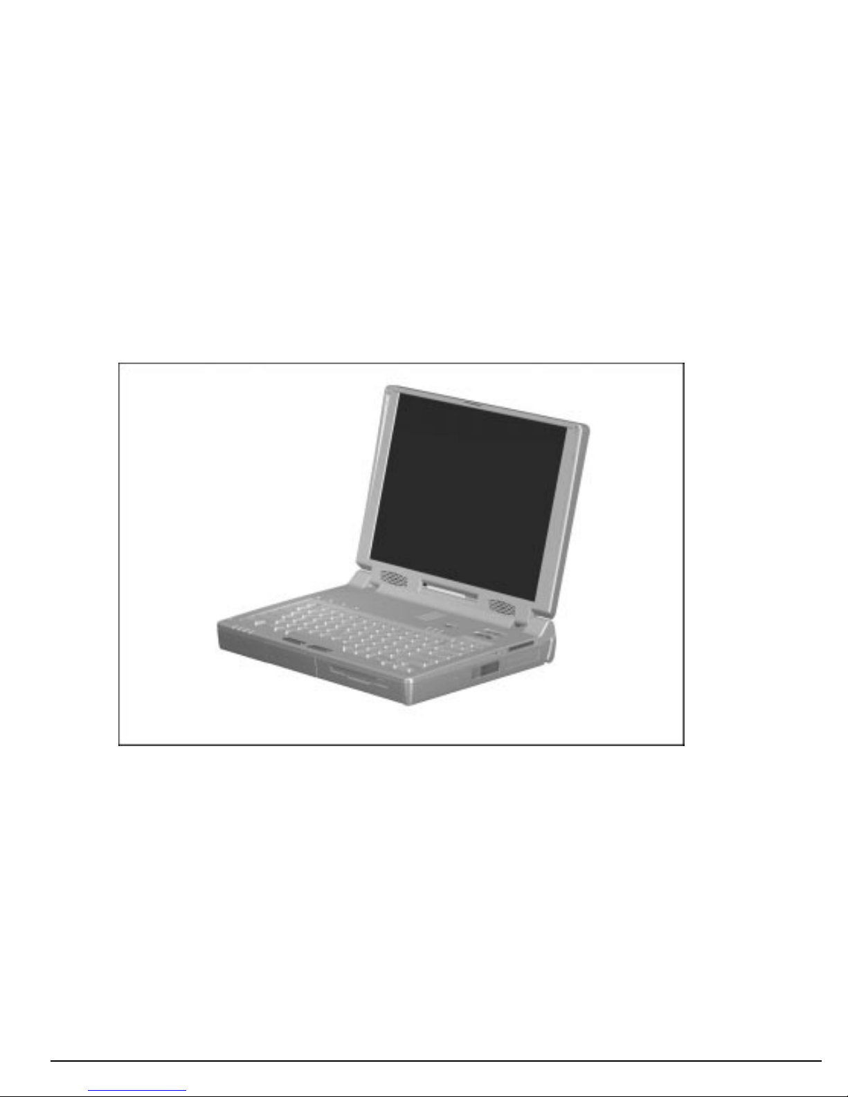
The Compaq Armada 7800 Family of Personal Computers offers advanced modularity,
an Intel Pentium II processor with 64-bit architecture, an industry-leading Accelerated
Graphics Port (AGP) implementation, and extensive multimedia support. The computer
provides desktop functionality and connectivity through the optional ArmadaStation
and Armada MiniStation.
Figure 1-1.
Compaq Armada 7800 Personal Computer
Features
The computer has the following standard features:
Intel 266-MHz Pentium II processor with 64-bit architecture, MMX technology, and
■
512-KB, level-2 cache memory
Industry-leading portable computer AGP implementation, featuring:
■
- 66-MHz dedicated graphics bus
- frame made AGP
4-MB SGRAM (synchronous graphics)
■
Product Description
1-1
Page 9

. . . . . . . . . . . . . . . . . . . . . . . . . . . . . . . . . . . . .
64-MB of SDRAM (synchronous): 32-MB on system board, 32-MB in memory
■
expansion compartment; expandable to 160 megabytes
Upgradable flash ROM BIOS
■
13.3 XGA (1024 × 768) TFT color display, true color (24-bit) support
■
Keyboard with built-in EasyPoint III pointing device and mouse buttons
■
Lithium ion (Li-ion) battery pack
■
Removable 5.0-GB hard drive
■
MultiBay that supports a CD-ROM drive, a second hard drive, a second battery pack,
■
or a diskette drive
Two PC Card slots that accept 32- and 16-bit Type I, II, and III PC Cards, with
■
zoomed video interface in the bottom slot
IrDa-compliant infrared port1 (4-Mbps standard) for wireless file transfer, printing,
■
and file synchronization
Built-in stereo speakers providing Compaq PremierSound, microphone, and jacks for
■
stereo audio sound with electronic equalization and wave table synthesis
Energy Star-compliant power saving features
■
Ports and connectors for external equipment, including universal serial bus (USB),
■
serial, parallel, external monitor, and PS/2-compatible pointing device or keyboard
Security features
■
Desktop functionality available with the optional Compaq ArmadaStation and
■
Armada MiniStation
Domestic and international modem and Ethernet connectivity
■
Integrated AC Adapter
■
Integrated 33.6-Kbps data/fax modem
■
1
IrDa 4MB compliant. Infrared performance may vary depending on performance of infrared peripherals, distance
between infrared devices, and applications used.
1-2
Product Description
Page 10

. . . . . . . . . . . . . . . . . . . . . . . . . . . . . . . . . . . . .
Models
The Armada 7800 models are shown in Table 1-1. The computer model designation is
composed of a group of characters that define each model’s characteristics.
Table 1-1
Models and Model Naming Convention
Compaq Armada 7800 Family of Personal Computers
Model
Armada 7800 6266 T 5000 D M 1 (64-MB RAM standard)
Armada 7800 6266 T 5000 D 0 1 (64-MB RAM standard)
Armada 7800 6266 T 5000 D 0 3 (64-MB RAM standard)
Armada 7800 78006266T5000 D M 1
Key A B C D E F G H I
Key Description Options
A Line designator 7 = Performance
B Family designator 8 = Armada 7800
C Processor type 6 =
D Processor speed 266 =
E Panel type T =
F Hard drive capacity 5000 = 5.0 GB
G Drive type D = 20X Max CD-ROM
H Modem M = Integrated modem
I Operating system &
software version
Intel Pentium II processor with MMX technology
266-MHz processor
13.3-inch XGA TFT 1024 × 768
V = DVD
0 = none
0 = No integrated modem
0 = No operating system
1 = Windows 95
2 = Windows 98
3 = Windows NT 4.0
4 = Windows NT 5.0
Product Description
1-3
Page 11

. . . . . . . . . . . . . . . . . . . . . . . . . . . . . . . . . . . . .
Intelligent Manageability
Intelligent Manageability consists of preinstalled software tools for the computer and
Compaq servers that assist in tracking, troubleshooting, protecting, and maintaining the
computer. It provides the following functions:
Asset Management—provides detailed configuration and diagnostic information.
■
Fault Management—prevents, predicts, and alerts of impending hardware problems.
■
Security Management—protects against unauthorized access to data and
■
components.
Integration Management—uses industry-standard technologies such as DMI and
■
SNMP to integrate with PC management software providers.
Configuration Management—optimizes the computer by providing the latest drivers,
■
utilities, and software, which are available on CD-ROM and the Compaq web site at
http://www.compaq.com.
NOTE: For further help with Intelligent Manageability, refer to Intelligent
Manageability Help. Click Start ⇒ Compaq Information Center ⇒ double-click
Intelligent Manageability Help.
Asset Management
AssetControl retrieves component information when on the road or connected to the
network.
AssetControl also enables the network administrator to remotely retrieve information
from any Compaq computer connected to the network. The information can be used to
assist in tracking and maintaining the computer and its components. It provides the
following information:
Inventory information—The network administrator can retrieve information about
■
the computer over the network by using Compaq Insight Manager or any PC
management tool provided by Compaq Solution Partners. AssetControl information
retrieved from the computer includes:
❑ Manufacturer, model, and serial number of Compaq computers, monitors, hard
drives, battery packs, memory boards, processor speeds, and operating systems.
❑ Asset tag
❑ System board and ROM revision levels
❑ BIOS settings
Diagnostic information—Diagnostics for Windows includes the information on hard
■
drives, ports, and video, sound, and other components. Compaq Diagnostics for
Windows can be accessed by clicking Start ⇒ Programs ⇒ Compaq Utilities ⇒
Compaq Diagnostics.
All of the above information can be viewed, printed, or saved.
1-4
Product Description
Page 12

. . . . . . . . . . . . . . . . . . . . . . . . . . . . . . . . . . . . .
Changing the Asset Tag Number
1. Turn on or restart the computer.
2. Press F10 when the cursor appears in the upper right corner of the screen.
3. Select Computer Setup ⇒ Intelligent Manageability.
4. Follow the instructions on the screen.
Fault Management
The Fault Management features minimize downtime and data loss by monitoring
system performance and generating the following alerts:
Hard drive alert—provides warning up to 72 hours in advance of impending hard
■
drive problems and can automatically start optional backup software.
System temperature alert—reports overheating. As the system temperature rises, this
■
feature first adjusts fan speed and other cooling components, then displays an alert,
then shuts down the system.
Battery pack alert—reports charging problems and battery pack failure.
■
Monitor alert—diagnoses and displays external monitor operational problems.
■
Memory alert—reports memory board configuration changes when a memory board
■
is removed, added, or reconfigured. It also provides the previous and current
configurations for comparison.
The alerts work with or without network connection. Of course, if the computer is not
connected to the network, the network administrator cannot receive alerts from the
computer.
Fault Management Alerts
Alerts can be enabled, disabled, and tested, and software can be set to back up
information whenever a hard drive alert occurs.
While the computer is connected to a network, alerts appear on the computer display
■
and are simultaneously reported to the network console.
NOTE: A battery charging problem alert is reported only on the computer display.
When the computer is not connected to a network, the user will receive a local alert.
■
To set alerts, double-click the Intelligent Manageability icon.
Product Description
1-5
Page 13

. . . . . . . . . . . . . . . . . . . . . . . . . . . . . . . . . . . . .
Security Management Overview
Security Management features customize system security.
Power-On and Setup Passwords—prevent unauthorized access to your information
■
and computer configuration.
DriveLock—prevents access to hard drives.
■
Device disabling—prevents unauthorized data transfer through modems, serial ports,
■
parallel ports, and infrared ports on the computer and an optional docking station.
QuickLock/QuickBlank—locks the keyboard and clears the screen.
■
Ownership Tag—displays ownership information during system restart.
■
Configuration Management
Configuration Management optimizes software upgrade and customer support
procedures. Compaq provides support software to optimize the performance of the
computer. This support software is accessible through a monthly subscription
CD-ROM. Support software can also be downloaded from the Compaq web site at
http://www.compaq.com. Support software includes:
Locator browser—searches for the latest device drivers, utilities, ROM images, and
■
other support software on a CD-ROM and at the Compaq web site at
http://www.compaq.com.
Decision Support—provides detailed information about drivers, utilities, and
■
software available on the computer. The information includes descriptions, features,
enhancements, dependencies, and necessary upgrades.
InfoMessenger—provides notifications by email when support software for the
■
computer becomes available.
1-6
Product Description
Page 14

. . . . . . . . . . . . . . . . . . . . . . . . . . . . . . . . . . . . .
1.2 Computer Components
The following table lists the components that ship with the computer and those that are
available as options. All components are available as spare parts. For more information
about ordering components, refer to Chapter 3, “Illustrated Parts Catalog.”
Table 1-2
Component Availability
Component Ships with Computer Available as Option
Battery pack ■■
Modem (not available in all locations) ■
Modem cable (country specific) ■■
Diskette drive ■
MultiBay weight saver ■
Slip case (shipped with computer only in
Europe, Middle East, and Africa)
EasyPoint III caps ■
Telephone cable (country specific) ■
Power cable ■
3-prong to 2-prong converter (Japan only) ■
Quck Restore CD-ROM ■
Security kit ■
ArmadaStation ■
Armada MiniStation E and EX ■
Memory expansion board ■
Battery charger ■
Automobile/aircraft adapter ■
Headset ■
Hard Drive MultiBay Adapter ■
20X CD-ROM drive ■■
5.0-GB hard drive ■■
■
Product Description
1-7
Page 15

. . . . . . . . . . . . . . . . . . . . . . . . . . . . . . . . . . . . .
The computer options are described in the following sections.
System Memory Options
The main memory subsystem supports a minimum standard 32 megabytes of
Synchronous SDRAM, expandable to 160 megabytes. The minimum standard
Synchronous SDRAM is integrated on the system board. The upgrade SDRAM is
accomplished with memory expansion boards that are available in 16-, 32-, and 64megabytes.
The memory expansion slot cover is secured to the computer by a Torx T-8 screw. A
tamper-resistant security screw, included with the computer, can be used to provide
added security. The security wrench, also included with the computer, must be used to
remove the tamper-resistant security screw.
System memory can be upgraded as shown in Table 1-3.
Table 1-3
Memory Upgrade
Base Memory on System Board Memory Expansion Board Total Memory
32 MB 16 MB (1 × 16 MB) 48 MB
32 MB 32 MB (2 × 16 MB or 1 × 32 MB) 64 MB
32 MB 48 MB (1 × 16 MB + 1 × 32 MB) 80 MB
32 MB 64 MB (2 × 32 MB or 1 × 64 MB) 96 MB
32 MB 80 MB (1 × 16 MB + 1 × 64 MB) 112 MB
32 MB 96 MB (1 × 32 MB + 1 × 64 MB) 128 MB
32 MB 128 MB (2 × 64 MB) 160 MB
The computer is shipped with 32-MB of memory on the system board and 32-MB in the memory expansion
compartment.
1-8
Product Description
Page 16

. . . . . . . . . . . . . . . . . . . . . . . . . . . . . . . . . . . . .
Mass Storage Devices
The following mass storage devices are available for the computer.
Table 1-4
Mass Storage Devices
Device Dimensions
Diskette drive 3.5-inch, 1.44-MB
Hard drive 5.0-GB (also available as an option)
CD-ROM drive 20-Speed Max (also available as an option)
LS-120 external
diskette drive
Diskette Drive
The computer uses a 3.5-inch diskette drive that fits into the computer, ArmadaStation,
or Armada MiniStation EX MultiBays. The diskette drive is a three-mode type that is
compatible with 1.44 Megabytes, 1.2 Megabytes, and 720 Kilobytes (formatted) AT
drive types. The system supports a maximum of two diskette drives: one in the
computer MultiBay and one in the ArmadaStation or Armada MiniStation EX
MultiBay.
120-MB
Hard Drive
The dedicated hard drive bay supports a removable 5.0-GB hard drive and the MultiBay
supports a second hard drive. Before a hard drive can be used in the MultiBay, it first
must be inserted in the Hard Drive MultiBay Adapter.
Product Description
1-9
Page 17

. . . . . . . . . . . . . . . . . . . . . . . . . . . . . . . . . . . . .
CD-ROM Drive
A 20-Speed Max CD-ROM drive comes as standard equipment with the computer. This
CD-ROM drive is also available as an option. The drive supports 3.5-inch and 5.25-inch
media in the following formats:
ISO-9660, the most common CD-ROM format
■
CD-ROM XA eXtended Architecture, a standard for storing multimedia information
■
Photo CD (single and multisession), Kodak's format for storing photographic images
■
on CD-ROM
CD-i and CD-i Bridge
■
CD-DA (digital audio)
■
CD-ROM Mode 1 and Mode 2
■
CD-I Mode 2 (Form 1 and Form 2)
■
Video CD
■
1-10
Product Description
Page 18

. . . . . . . . . . . . . . . . . . . . . . . . . . . . . . . . . . . . .
Battery Equipment Options
The following battery options are available:
Automobile/Aircraft Adapter
■
Lithium ion battery pack
■
Battery Charger
■
Automobile/Aircraft Adapter
The Automobile/Aircraft Adapter allows the computer to operate from a 12-volt aircraft
DC socket and from an automobile cigarette lighter receptacle.
Lithium Ion Battery Pack
The battery pack can be used in the computer dedicated battery bay, computer
MultiBay, ArmadaStation MultiBays, and Armada MiniStation EX MultiBay and
battery charging bay.
Battery Charger
The external Battery Charger has the following features:
Two battery charging bays
■
Charging of one battery in 1.5 hours
■
Charging of two batteries in 3 hours
■
Product Description
1-11
Page 19

. . . . . . . . . . . . . . . . . . . . . . . . . . . . . . . . . . . . .
1.3 Computer External Components
The external components on the display, front, and left side of the computer are shown
in Figure 1-2 and described in Table 1-5.
Figure 1-2.
Display, Front, and Left Side Components
Table 1-5
Display, Front, and Left Side Components
Item Component Function
1 Display release latch Opens the computer.
2 Mono Microphone Allows for audio input; located on the inside and outside of the
display, can be used whether the computer is open or closed.
3 Stereo speakers (2) Produce high-quality stereo sound.
4 Tilt feet (2) Tilt the computer for ease of use.
5 Fan Provides airflow exhaust.
6 Battery bay Accepts Lithium ion battery pack.
7 Hard drive bay Accepts removable hard drive.
8 MultiBay Accepts MultiBay devices: CD-ROM drive, diskette drive, hard
drive (in Hard Drive MultiBay Adapter), LS-120 MultiBay Drive,
battery pack.
1-12
Product Description
Page 20
. . . . . . . . . . . . . . . . . . . . . . . . . . . . . . . . . . . . .
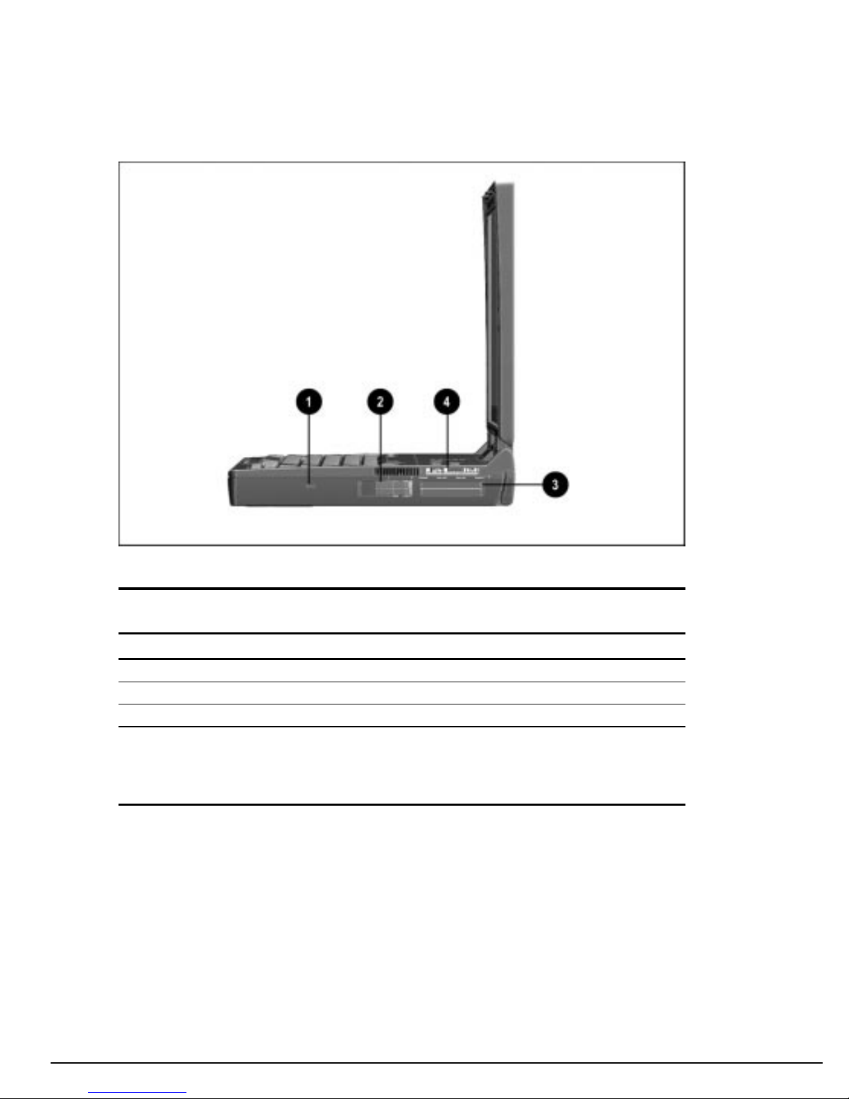
The external components on the right side of the computer are shown in Figure 1-3 and
are described in Table 1-6.
Figure 1-3.
Right Side Components
Table 1-6
Right Side Components
Item Component Function
1 Security slot Secures the computer to a fixed object to prevent theft.
2 PC Card eject levers (2) Eject PC Cards from the slots.
3 PC Card slots Accepts 16- and 32-bit CardBus PC Cards.
4 25-pin modem connector Connects a country-specific 25-pin telephone cable (all
countries except North America, Latin America, Japan, China,
and Hong Kong).
Also connects a cellular phone to the computer (U.S. only).
Product Description
1-13
Page 21
. . . . . . . . . . . . . . . . . . . . . . . . . . . . . . . . . . . . .
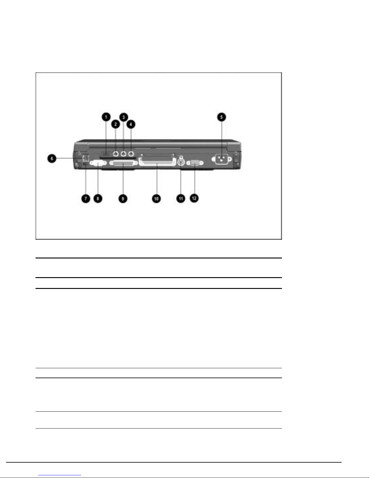
The external components on the rear panel of the computer are shown in Figure 1-4 and
are described in Table 1-7.
Figure 1-4.
Rear Panel Components
Table 1-7
Rear Panel Components
Item Component Function
1 Universal serial bus (USB)
connector
2 Mono microphone jack Connects mono microphone, disabling the built-in microphone.
3 Stereo speaker/headphone jack Connects external stereo speakers, headphones, or headset.
4 Stereo line-in jack Connects external device such as a CD player, tuner, or tape
Connects USB devices, such as cameras for video conferencing,
or hubs which connect multiple USB devices.
The USB connector is a powered hub. When running Windows
95 or higher or Windows NT or higher, any combination of up to
five powered or unpowered hubs can be connected in any
sequence, as long as two unpowered hubs are not connected
next to each other.
When running a lower version of Windows or Windows NT, or if
using a different operating system, up to two hubs can be
connected.
This jack is driven by an amplifier and has volume control. The
internal computer speakers are turned off when external
speakers or headphones are plugged into this jack.
deck.
Continued
1-14
Product Description
Page 22

. . . . . . . . . . . . . . . . . . . . . . . . . . . . . . . . . . . . .
Table 1-7
5 Power cord connector Connects external (AC) power.
6 RJ-11 modem jack Connects a standard telephone cable for a modem in North
7 Infrared port Provides wireless communication between the computer and
8 Serial connector Connects optional serial devices such as a mouse.
9 Parallel connector Connects optional parallel devices such as a printer.
10 Docking connector Connects optional ArmadaStation or Armada MiniStation E or EX.
11 Keyboard/mouse connector Connects an optional full-sized keyboard or a mouse. Both
12 External monitor connector Connects an optional external monitor. Also connects a
Continued
America, Latin America, Japan, China, and Hong Kong only.
another infrared-equipped device using an infrared beam.
external mouse and computer pointing device are active. An
optional splitter/adapter allows both an external keyboard and
mouse to be used at the same time.
television adapter.
Product Description
1-15
Page 23

. . . . . . . . . . . . . . . . . . . . . . . . . . . . . . . . . . . . .
Computer keyboard components are shown in Figure 1-5 and described in Table 1-8.
Figure 1-5.
Computer Components: Keyboard
Table 1-8
Keyboard Components
Item Component Function
1 Display switch Turns off the display if it is closed while the computer is turned
on. The computer beeps unless audio has been disabled.
2 Vents Allows airflow to cool the computer.
3 Suspend button Toggles on to initiate or off to exit Suspend.
4 Volume control Adjusts volume of stereo speakers.
5 Power switch Turns computer on or off.
6 Scroll lock key Turns on the scroll function.
7 Page up and page down keys Moves image to previous or following screen.
8 Num Lk key Turns on the numeric lock function.
9 Embedded numeric keypad Converts keys to numeric keypad.
10 Cursor-control keys Moves the cursor around the screen.
11 Fn key Used with hotkeys to perform preset hotkey functions.
12 Caps lock key Turns on the caps lock function.
13 F1 through F12 function keys Perform preset functions.
14 Programmable keys Assign and launch frequently used documents or applications
and emulate Windows and Application Logo Keys.
1-16
Product Description
Page 24

. . . . . . . . . . . . . . . . . . . . . . . . . . . . . . . . . . . . .
Additional computer keyboard components are shown in Figure 1-6 and described in
Table 1-9.
Figure 1-6.
Keyboard Components (continued)
Table 1-9
Keyboard Components (continued)
Item Component Function
1 Power/suspend light (green) Turns on when computer is turned on; blinks in Suspend; turns
off when computer is in Hibernation or turned off.
2 Battery power light (orange) Turns on when a battery pack in the battery bay is charging or
waiting to charge. Turns off when battery pack is fully charged.
Blinks 6 times if low-battery condition is reached. Blinks
continuously if critical low-battery condition is reached. If AC
power is not connected within 20 seconds, Hibernation is
initiated (unless Hibernation has been disabled).
3 Hard drive light (green) Turns on when the hard drive is being accessed.
4 MultiBay drive light (green) Turns on when the MultiBay device is being accessed or when a
battery pack in the MultiBay is charging or waiting to be
charged.
5 Left and right mouse buttons Function like left and right mouse buttons on an external mouse.
6 EasyPoint III pointing device Moves the cursor across the screen.
7 Caps lock light Turns on when the Caps Lock function is on.
8 Scroll lock light Turns on when Scroll function is on.
9 Numeric lock light Turns on when the Numeric Lock function is on.
Product Description
1-17
Page 25

. . . . . . . . . . . . . . . . . . . . . . . . . . . . . . . . . . . . .
The external components on the bottom of the computer are shown in Figure 1-7 and
are described in Table 1-10.
Figure 1-7.
Bottom Components
Table 1-10
Bottom Components
Item Component Function
1 Battery release latch Releases the battery from the battery bay.
2 Hard drive release latch Releases the hard drive from the hard drive bay.
3 Docking restraint latch recess Secures the computer to the ArmadaStation.
4 Hard drive/MultiBay security
screw slot
5 MultiBay release latch Releases devices from the MultiBay.
6 Memory expansion slot cover Covers the memory expansion compartment.
7 Labels area Contains labels that describe the computer model and provide
8 Serial number Numerical identification for the computer.
Allows hard drives and MultiBay devices to be secured inside the
computer using the single and dual bay security screws.
agency and modem information.
1-18
Product Description
Page 26

. . . . . . . . . . . . . . . . . . . . . . . . . . . . . . . . . . . . .
1.4 Design Overview
This section presents a design overview of key parts and features of the computer. For
assembly/disassembly instructions for the parts described in this section, refer to
Chapter 5.
System Board
The system board provides the following device connections:
Memory expansion board
■
Diskette drive
■
Hard drive
■
CD-ROM drive
■
Display
■
Keyboard/EasyPoint III pointing device
■
Audio
■
Pentium II processor
■
Fan
■
PC Cards
■
Modem
■
The computer is equipped with a 3.1-volt, Intel Mobile Pentium II 266-MHz processor.
For ventilation, an electrical fan is installed. The fan operates on from 5 to 12 volts and
is controlled by a temperature sensor. The fan is designed to turn on automatically when
high temperature conditions exist. These conditions are affected by high external
temperatures, system power consumption, power management/battery conservation
configurations, battery fast charging, and software applications. Exhaust air is displaced
through the ventilation grill located on the left side of the computer.
CAUTION:
on the left and right sides of the computer.
To properly ventilate the computer, allow at least a 3-inch (7.6 cm) clearance
Product Description
1-19
Page 27

. . . . . . . . . . . . . . . . . . . . . . . . . . . . . . . . . . . . .
Chapter 2
Troubleshooting
Follow these basic steps when beginning the troubleshooting process:
1. Complete the preliminary steps listed in Section 2.1.
2. Run the Power-On Self-Test (POST) as described in Section 2.3.
3. Run Computer Setup as described in Section 2.5.
4. Run the Computer Checkup (TEST) as described in Section 2.6.
5. If you are unable to run POST or Computer Checkup or if the problem persists after
running POST and Computer Checkup, perform the recommended actions
described in the diagnostic tables in Section 2.5.
Follow these guidelines when troubleshooting:
■ Complete the recommended actions in the order in which they are given.
■ Repeat POST and Computer Checkup after each recommended action until the
problem is resolved and the error message does not return.
■ When the problem is resolved, stop performing the troubleshooting steps and do not
complete the remaining recommended actions.
■ Refer to Chapter 5 for removal and replacement procedures that are recommended.
■ If the problem is intermittent, check the computer several times to verify that the
problem is solved.
The following table describes the troubleshooting actions:
If You Want To: Then Run:
Check for POST error messages POST
Check that computer components are recognized and
running properly
View information about the computer and installed or
connected devices
Perform any of the following:
■ Check the system configuration
■ Set the system power management parameters
■ Return the system to its original configuration
■ Check system configuration of installed devices
Computer Checkup (TEST) under Compaq Utilities
View System Information (INSPECT) under
Compaq Utilities
Computer Setup
Troubleshooting
2-1
Page 28

. . . . . . . . . . . . . . . . . . . . . . . . . . . . . . . . . . . . .
2.1 Preliminary Steps
IMPORTANT: Use AC power when running POST, Computer Setup, or Computer
Checkup. A low battery condition could initiate Hibernation and interrupt the test.
Before running POST and Computer Checkup, complete the following steps:
1. Obtain established passwords. If you must clear the passwords, go to Section 2.2.
2. Ensure that the hard drive is installed in the computer.
3. Ensure that the battery pack is installed in the computer and the power cord is
connected to the computer and plugged into an AC power source.
4. Turn on the computer.
5. If a power-on password has been established, type the password and press Enter.
6. Run Computer Setup (Section 2.5). If a Setup password has been established, type
the password and press Enter.
7. Turn off the computer and all external devices.
8. Disconnect external devices that you do not want to test. If you want to use the
printer to log error messages, leave it connected to the computer.
NOTE: If a problem only occurs when an external device is connected to the computer,
the problem could be with the external device or its cable. Isolate the problem by
running POST with and without the external device connected.
9. Use Compaq Utilities and loopback plugs in the serial and parallel connectors if you
plan to test these ports.
Follow these steps to run Compaq Utilities:
a. If you are running Compaq Utilities from the hard drive, turn on or restart the
computer. Press F10 when the cursor appears in the upper-right corner of the
screen. If you do not press F10 in time, restart the computer and try again.
If you are running Compaq Utilities from diskette, insert the Compaq Utilities
diskette in drive A. Turn on or restart the computer.
b. Press Enter to accept OK.
c. Select Computer Checkup (TEST).
d. Select Prompted Diagnostics.
e. After “Identifying System Hardware” completes, select Interactive Testing and
follow the instructions on the screen.
2-2
Troubleshooting
Page 29

. . . . . . . . . . . . . . . . . . . . . . . . . . . . . . . . . . . . . .
2.2 Clearing Passwords
1. Turn off the computer.
2. Disconnect the power cord (refer to Section 5.4).
3. Remove the battery pack (Section 5.7).
4. Remove the keyboard (Section 5.11).
5. Remove the audio/USB board (Section 5.14).
6. Remove the modem board (Section 5.15).
7. Remove the audio assembly bracket (Section 5.16).
8. Remove the lithium disc cell battery (Section 5.17).
9. Disconnect the auxiliary battery (Section 5.19).
10. Allow the computer to set for five minutes.
11. Reconnect the auxiliary battery.
12. Install the lithium disc cell battery.
13. Install the audio assembly bracket, modem board, audio/USB board, and keyboard.
14. Reconnect the power cord. Do not
15. Turn on the computer.
NOTE: Remember to set the date and time the next time the computer is turned on.
reinstall the battery pack yet.
Troubleshooting
2-3
Page 30

. . . . . . . . . . . . . . . . . . . . . . . . . . . . . . . . . . . . .
2.3 Power-On Self-Test (POST)
The Power-On Self-Test (POST) is a series of tests that run every time the computer is
turned on. POST verifies that the system is configured and functioning properly.
To run POST, complete the following steps:
1. Complete the preliminary steps (Section 2.1).
2. Turn on the computer.
If POST does not detect any errors, the computer beeps once or twice to indicate that
POST has run successfully. The computer boots from the hard drive or from a bootable
diskette if one is installed in the diskette drive.
2.4 POST Error Messages
If the system is not functioning well enough to run POST, or if the display is not
functioning well enough to show POST error messages, refer to the Troubleshooting
tables in Section 2.7.
If POST detects an error, one of the following events occurs:
■ A message with the prefix "WARNING" appears, informing you where the error
occurred. The system pauses until you press F1 to continue.
■ A message with the prefix "FATAL" appears, informing you where the error
occurred. After the message, the system emits a series of beeps, then stops.
■ The system emits a series of beeps, then stops.
Warning messages indicate that a potential problem, such as a system configuration
error, exists. When F1 is pressed, the system should resume. You should be able to
correct problems that produce WARNING messages.
IMPORTANT: When a WARNING message includes the prompt to "RUN SCU," press
F10 to run Computer Setup. (Computer Setup replaces the SCU utility.)
2-4
Troubleshooting
Page 31

. . . . . . . . . . . . . . . . . . . . . . . . . . . . . . . . . . . . . .
If you receive one of the error messages listed below, follow the recommended action.
Table 2-1
Warning Messages
Message Description Recommended Action
CMOS checksum invalid, run SCU CMOS RAM information has
been corrupted.
CMOS failure, run SCU CMOS RAM has lost power. Run Computer Setup to reinitialize
Diskette controller error The diskette drive controller
failed to respond to the
recalibrate command.
Diskette track 0 failed The diskette drive cannot read
track 0 of the diskette in the
drive.
Hard disk controller error The hard drive controller failed
to respond to the reset
command.
Keyboard controller failure The keyboard failed the self-test
command.
Keyboard failure The keyboard failed to respond
to the RESET ID command.
No interrupts from Timer 0 The periodic timer interrupt is
not occurring.
ROM at xxxx (LENGTH yyyy) with
nonzero checksum (zz)
Time/Date corrupt - run SCU The time and date stored in the
Hard disk xx failure (or error) A failure or an error occurred
An illegal adapter ROM was
located at the specified address.
real time clock have been
corrupted, possibly by a power
loss.
when trying to access the hard
drive.
Run Computer Setup to reinitialize
CMOS-RAM.
CMOS-RAM.
If there is no diskette drive in the
system, run Computer Setup to
properly configure the CMOS-RAM to
show no diskette drive present. If the
problem persists, or if a diskette drive
is present, complete these steps until
the problems is solved:
1. Check diskette drive connections.
2. Replace diskette drive.
3. Replace system board.
Try another diskette. If the problem
persists, you may need to replace the
diskette drive.
Check the drive parameters. Turn off
the system and check all related
connections.
Replace the system board.
Replace the keyboard. If the problem
persists, replace the system board.
Replace the system board.
Check the external adapter (such as a
video card) to determine if it is causing
the conflict.
1. Run Computer Setup.
2. If problem persists, replace
auxiliary battery.
3. If problems persists, replace system
board.
1. Run Scan disk.
2. Check disk in DOS and
Windows 95. If problem persists,
refer to Table 2-10.
Troubleshooting
2-5
Page 32

. . . . . . . . . . . . . . . . . . . . . . . . . . . . . . . . . . . . .
Fatal errors emit a beep and may display a FATAL message. Fatal errors indicate severe
problems, such as a hardware failure. Fatal errors do not allow the system to resume.
Some of the Fatal error beep codes are listed at the end of this section.
Table 2-2
Fatal Error Messages
Message Description Beep Code*
CMOS RAM test failed A walking bit test of CMOS RAM location 0E
(Hex) - 3F (Hex) failed.
DMA controller faulty A sequential read/write of the transfer count
and transfer address registers within the
primary and secondary DMA controllers failed.
Faulty DMA page registers A walking bit read/write of the 16 DMA
controller page registers starting at location 80
Hex failed.
Faulty refresh circuits A continuous read/write test of port 61h found
that bit 4 (Refresh Detect) failed to toggle
within an allotted amount of time.
Interrupt controller failed A sequential read/write of various Interrupt
Controller registers failed.
ROM checksum incorrect A checksum of the ROM BIOS does not match
the byte value at F000:FFFF.
RAM error at location xxxx RAM error occurred during memory test. None
*
Beep codes are defined in Table 2-3.
3
4
0
1
5
2
2-6
Troubleshooting
Page 33

. . . . . . . . . . . . . . . . . . . . . . . . . . . . . . . . . . . . . .
Table 2-3
Fatal Error Beep Codes
Beep Code Beep Sequence Description Recommended Action
0 S-S-S-P-S-S-L-P The DMA page registers are faulty. Replace system board.
1 S-S-S-P-S-L-S-P The refresh circuitry is faulty.
2 S-S-S-P-S-L-L-P The ROM checksum is incorrect.
3 S-S-S-P-L-S-S-P The CMOS RAM test failed.
4 S-S-S-P-L-S-L-P The DMA controller is faulty.
5 S-S-S-P-L-L-S-P The interrupt controller failed.
6 S-S-S-P-L-L-L-P The keyboard controller failed.
7 S-S-L-P-S-S-S-P Graphics adapter is faulty.
8 S-S-L-P-S-S-L-P Internal RAM is faulty. Replace memory board or
system board if memory on
system board is faulty.
NOTE:
S = Short, L = Long, P = Pause
Troubleshooting
2-7
Page 34

. . . . . . . . . . . . . . . . . . . . . . . . . . . . . . . . . . . . .
2.5 Compaq Utilities
Compaq Utilities contain several functions that
■ Determine if various computer devices are recognized by the system and are
operating properly.
■ Provide information about the system once it is configured.
Compaq Utilities include the following programs:
■ Computer Setup
■ Computer Checkup (TEST)
■ View System Information (INSPECT)
To access Compaq Utilities:
1. Turn on or restart the computer by clicking Start ➔ Shut Down ➔ Restart the
computer.
2. Press F10 when the blinking cursor appears in the upper-right corner of the display.
3. Select a menu option.
Computer Setup
Computer Setup contains utilities that give you an overall picture of the computer
hardware configuration and aid in troubleshooting. These utilities also allow you to set
custom features such as security options, power conservation levels, and startup
preferences.
If you are running Windows 95, the computer automatically recognizes and configures
the system for new devices. If you have a configuration problem or want to view or
reset configuration settings, you can use Computer Setup.
NOTE: If you are running Windows 95, you should use Computer Setup only to adjust
system features such as the power-on password or battery conservation level. Windows
95 may override other configuration changes.
If you are running Windows NT, the computer does not automatically recognize new
devices added to the system. All devices ordered with your system have been
configured for you. Use Computer Setup to view settings for a new device you have
added or to reset configuration settings for preinstalled devices.
Computer Setup provides two methods of viewing the computer configuration: by type
(factory setting) or connection.
2-8
Troubleshooting
Page 35

. . . . . . . . . . . . . . . . . . . . . . . . . . . . . . . . . . . . . .
Categories by type:
■ System Features—security, power, boot management
■ Communication—port, modem, and other communication devices
■ Storage—storage-related devices such as hard drive, CD-ROM drive, diskette drive
■ Input Devices—keyboard, mouse, and other input devices
■ Network—network adapter or other network-related devices
■ Audio—sound properties and audio device settings
■ Video—display timeouts and video device resources
■ Other—miscellaneous devices
Categories by connection:
■ System Features—security, power, boot management
■ System Devices—keyboard, mouse, parallel and serial ports
■ ISA—ISA bus and connected devices
■ PCI—PCI bus and connected devices
■ PC Card—PC Card devices
Running Computer Setup
1. Turn on or restart the computer by clicking Start ➔ Shut Down ➔ Restart the
computer.
2. Press F10 when the blinking cursor appears in the upper-right corner of the screen.
NOTE: If you a setup password is enabled, it must be used to access Computer Setup.
3. Click a language and press Enter.
4. Click Computer Setup and press Enter.
5. When you are finished, click Exit.
Troubleshooting
2-9
Page 36

. . . . . . . . . . . . . . . . . . . . . . . . . . . . . . . . . . . . .
Exiting Computer Setup
1. Click Exit.
2. Select one of the following Exit options:
■ Save—Saves the new settings and exits Computer Setup.
NOTE: Some settings may not take effect until the computer is restarted.
■ Ignore—Exits Computer Setup and restores previous settings.
■ Cancel—Returns to Computer Setup.
Computer Checkup (TEST)
Computer Checkup (TEST) determines whether the various computer components and
devices are recognized by the computer and are functioning properly. You can display,
print, or save the information that Computer Checkup generates.
NOTE: Compaq Utilities are intended for testing only Compaq-supplied components.
Testing of non-Compaq components may be inconclusive.
Running Computer Checkup (TEST)
1. Plug the computer into an external power source. A low battery condition can
interrupt the program.
2. Connect a printer if you want to print a log of error messages.
3. Turn on the external devices that you want to test.
4. Turn on or restart the computer.
5. Access Compaq Utilities by pressing F10 when the blinking cursor appears in the
upper-right corner of the display.
6. Click Computer Checkup ➔ View the Device List.
■ If the list of installed devices is correct, click OK.
■ If the list is incorrect, ensure that any new devices are installed properly.
2-10
Troubleshooting
Page 37

. . . . . . . . . . . . . . . . . . . . . . . . . . . . . . . . . . . . . .
7. Select one of the following from the Test Option menu:
■ Quick Check Diagnostics
■ Automatic Diagnostics
■ Prompted Diagnostics
8. Follow the instructions on the screen as the devices are tested.
9. Click Exit Diagnostics ➔ Exit from this utility.
Computer Checkup (TEST) Error Codes
Computer Checkup (TEST) error codes occur if the system recognizes a problem while
running Computer Checkup. These error codes help identify possibly defective
assemblies. Tables 2-4 through 2-14 list Computer Checkup error codes, a description
of the error condition, and the recommended action for resolving the condition. For
removal and replacement procedures, refer to Chapter 5.
IMPORTANT: Run Computer Checkup each time you complete a recommended action
step. If the problem is resolved when POST and Computer Checkup are rerun (i.e., with
no error codes), do not perform the remaining recommended action steps.
NOTE: The error codes in the following tables are listed in an “AYY-XX” format,
where:
A or AA = Number that represents the faulty assembly
YY = Test or action that failed
XX = Specific problem
Table 2-4
Processor Test Error Codes
Error Code Description Recommended Action
101-xx CPU test failed. Replace the processor board and retest.
103-xx DMA page registers test failed. Replace the system board and retest.
104-xx Interrupt controller master test failed.
105-xx Port 61 error.
106-xx Keyboard controller self-test failed.
107-xx CMOS RAM test failed.
108-xx CMOS interrupt test failed.
109-xx CMOS clock test failed.
110-xx Programmable timer load data test failed.
113-xx Protected mode test failed.
Troubleshooting
2-11
Page 38

. . . . . . . . . . . . . . . . . . . . . . . . . . . . . . . . . . . . .
Table 2-5
Memory Test Error Codes
Error Code Description Recommended Action
200-xx Memory machine ID test failed. The following steps apply to error codes 200-xx
and 202-xx:
202-xx Memory system CMOS checksum failed.
203-xx Write/Read test failed. The following applies to error codes 203-xx
204-xx Address test failed. Remove and replace the memory board or system
211-xx Random pattern test failed.
214-xx Noise test failed.
215-xx Random address test failed.
Table 2-6
Keyboard Test Error Codes
1. Flash the system CMOS and retest.
2. Replace the system board and retest.
through 215-xx:
board (if the memory board on the system board
is faulty) and retest.
Error Code Description Recommended Action
300-xx Failed ID Test. The following steps apply to error codes 300-xx
through 304-xx:
1. Reseat the keyboard assembly.
301-xx Failed Self test/Interface Test. 2. Replace the keyboard and retest.
302-xx Failed Individual Key Test. 3. Replace the system board and retest.
304-xx Failed Keyboard Repeat Test.
Table 2-7
Parallel Printer Test Error Codes
Error Code Description Recommended Action
401-xx Printer failed or not connected. The following steps apply to error codes 401-xx
through 403-xx:
1. Connect the printer.
402-xx Failed Port Test. 2. Check power to the printer.
403-xx Printer pattern test failed. 3. Install the loopback connector and retest.
4. Check port and IRQ configuration.
5. Replace the system board and retest.
2-12
Troubleshooting
Page 39

. . . . . . . . . . . . . . . . . . . . . . . . . . . . . . . . . . . . . .
Table 2-8
Diskette Drive Error Codes
Error Code Description Recommended Action
600-xx Diskette ID drive types test
failed.
601-xx Diskette format failed. 1. Replace the diskette.
602-xx Diskette read test failed. 2. Replace the diskette drive and retest.
603-xx Diskette write, read, compare test failed. 3. Replace the system board and retest.
604-xx Diskette random read test failed.
605-xx Diskette ID media test failed.
606-xx Diskette speed test failed.
609-xx Diskette reset controller test failed.
610-xx Diskette change line test failed.
697-xx Diskette type error.
698-xx Diskette drive speed not within limits.
699-xx Diskette drive/media ID error. 1. Replace media.
The following steps apply to error codes 600-xx
through 698-xx:
2. Run Compaq Utilities.
Table 2-9
Serial Test Error Codes
Error Code Description Recommended Action
1101-xx Serial port test failed. 1. Check port configuration.
2. Replace the system board and retest.
Troubleshooting
2-13
Page 40

. . . . . . . . . . . . . . . . . . . . . . . . . . . . . . . . . . . . .
Table 2-10
Hard Drive Test Error Codes
Error Code Description Recommended Action
1701-xx Hard drive format test failed. The following steps apply to error codes 1701-xx
through 1736-xx:
1. Run Compaq Utilities and verify drive type.
1702-xx Hard drive read test failed.
1703-xx Hard drive write/read/compare test failed. 3. Replace the hard drive and retest.
1704-xx Hard drive random seek test failed. 4. Replace the system board and retest.
1705-xx Hard drive controller test failed.
1706-xx Hard drive ready test failed.
1707-xx Hard drive recalibration test failed.
1708-xx Hard drive format bad track test failed.
1709-xx Hard drive reset controller test failed.
1710-xx Hard drive park head test failed.
1715-xx Hard drive head select test failed.
1716-xx Hard drive conditional format test failed.
1717-xx Hard drive ECC* test failed.
1719-xx Hard drive power mode test failed.
1724-xx Network preparation test failed.
1736-xx Drive monitoring test failed.
2. Verify that all secondary drives have secondary
drive capability.
*ECC = Error Correction Code
2-14
Troubleshooting
Page 41

. . . . . . . . . . . . . . . . . . . . . . . . . . . . . . . . . . . . . .
Table 2-11
Video Test Error Codes
Error Code Description Recommended Action
501-xx Video controller test failed. The following actions apply to error codes 501-xx
through 516-xx:
502-xx Video memory test failed. 1. Disconnect external monitor and test with
internal LCD display.
503-xx Video attribute test failed. 2. Replace the display assembly and retest.
504-xx Video character set test failed. 3. Replace the system board and retest.
505-xx Video 80 × 25 mode 9 × 14 character
cell test failed.
506-xx Video 80 × 25 mode 8 × 8 character
cell test failed.
507-xx Video 40 × 25 mode test failed.
511-xx Video screen memory page test failed.
512-xx Video gray scale test failed.
514-xx Video white screen test failed.
516-xx Video noise pattern test failed.
2402-xx Video memory test failed. The following actions apply to error codes
2402-xx through 2456-xx:
2403-xx Video attribute test failed. 1. Run Compaq Utilities.
2404-xx Video character set test failed. 2. Disconnect external monitor and test with
internal LCD display.
2405-xx Video 80 × 25 mode 9 × 14 character cell
test failed.
2406-xx Video 80 × 25 mode 8 × 8 character cell test
failed.
2411-xx Video screen memory page test failed.
2412-xx Video gray scale test failed.
2414-xx Video white screen test failed.
2416-xx Video noise pattern test failed.
2418-xx ECG/VGC memory test failed.
2419-xx ECG/VGC ROM checksum test failed.
2421-xx ECG/VGC 640 × 200 graphics mode test
failed.
2422-xx ECG/VGC 640 × 350 16 color set test failed.
2423-xx ECG/VGC 640 × 350 64 color set test failed.
2424-xx ECG/VGC monochrome text mode test failed.
2425-xx ECG/VGC monochrome graphics mode test
failed.
2431-xx 640 × 480 graphics test failed.
2448-xx Advanced VGA Controller test failed.
3. Replace the display assembly and retest.
4. Replace the system board and retest.
Continued
Troubleshooting
2-15
Page 42

. . . . . . . . . . . . . . . . . . . . . . . . . . . . . . . . . . . . .
Table 2-11
Continued
Error Code Description Recommended Action
2451-xx 132-column Advanced VGA test failed.
2456-xx Advanced VGA 256 Color test failed.
2458-xx Advanced VGA Bit BLT test failed. The following action applies to error codes
2458-xx to 2480-xx:
2468-xx Advanced VGA DAC test failed. Replace the system board and retest.
2477-xx Advanced VGA data path test failed.
2478-xx Advanced VGA BitBLT test failed.
2480-xx Advanced VGA Linedraw test failed.
NOTE:
Refer to Table 2-25 for information about other video errors.
Table 2-12
Audio Test Error Codes
Error Code Description Recommended Action
114-01 Speaker test failed.
3206-xx Audio System Internal Error Replace the audio board and retest.
1. Check system configuration.
2. Verify display audio cable connection.
Table 2-13
Pointing Device Interface Test Error Codes
Error Code Description Recommended Action
8601-xx Pointing device test failed. The following action applies to error codes 8601-
xx and 8602-xx.
Replace the keyboard/CPU cover assembly.
8602-xx Interface test failed.
Table 2-14
CD-ROM Test Error Codes
Error Code Description Recommended Action
3301-xx CD-ROM drive read test failed. The following action applies to error codes 3301-
xx and 3305-xx and 6600-xx through 6623-xx.
1. Replace the CD and retest.
2. Verify that drivers are loaded and properly
installed.
3305-xx CD-ROM drive seek test failed. 3. Replace the CD-ROM drive and retest.
4. Replace the system board and retest.
6600-xx ID test failed.
6605-xx Read test failed.
6608-xx Controller test failed.
6623-xx Random read test failed.
2-16
Troubleshooting
Page 43

. . . . . . . . . . . . . . . . . . . . . . . . . . . . . . . . . . . . . .
Running View System Information
(INSPECT)
The View System Information (INSPECT) utility provides information about the
computer and installed or connected devices. You can display, print, or save the
information.
1. Connect a printer if you want to print the INSPECT information.
2. Turn on or restart the computer.
3. Access Compaq Utilities by pressing F10 when the cursor blinks in the upper-right
corner of the display.
4. If prompted, select a language.
5. Click View System Information (INSPECT).
6. Click the item you want to view from the following list:
■ System ■ Audio
■ ROM ■ Operating system
■ Keyboard ■ System files
■ System ports ■ Windows files
■ System storage ■ Miscellaneous
■ Graphics
■ Memory
7. Follow the instructions on the screen to cycle through the screens, to return to the list
and choose another item, or to print the information.
8. Select Exit Inspect.
■ Network (applicable only if
computer is docked in the
ArmadaStation or Armada
MiniStation)
Troubleshooting
2-17
Page 44

. . . . . . . . . . . . . . . . . . . . . . . . . . . . . . . . . . . . .
Running Compaq Diagnostics
Compaq Diagnostics provides computer component information when the operating
system is working.
If you are running Windows 95, access Compaq Diagnostics for Windows by
double-clicking My Computer ➔ Control Panel ➔ Compaq Diagnostics.
If you are running Windows NT, access Windows NT Diagnostics by clicking Start ➔
Programs ➔ Administrative Tools ➔ Windows NT Diagnostics.
Boot Sequencing
1. Run Computer Setup.
2. Click the System Features icon ➔ Boot Management box ➔ MultiBoot tab.
3. Designate the hard drive boot (startup) sequence you want.
4. Click OK to accept the changes.
Factory Default Settings
Table 2-15
Initialization
Enable POST Memory Test Checked (enabled)
Keyboard Num Lock Unchecked (Off)
1 Hard drive in the computer hard drive bay
2 Hard drive in the computer MultiBay
3 Hard drive in the ArmadaStation or Armada
MiniStation
4 Hard drive in the ArmadaStation half-height bay (if
converted to a MultiBay)
Boot display Auto
Language Language of country
Table 2-16
Ports
Serial port 3F8, IRQ4
Infrared port 3F8, IRQ4
Parallel port 3F8, IRQ7
Ethernet port 300, IRQ9
2-18
Troubleshooting
Page 45

. . . . . . . . . . . . . . . . . . . . . . . . . . . . . . . . . . . . . .
Table 2-17
Power
Low Battery Warning Beep Checked (enabled)
External Energy Saving Monitor Connected Unchecked (not connected)
Power Management
Enabled While operating power on battery
Conservation Level Medium
Level Definition
High Suspend Time: 5 minutes
Hibernation Timeout: Immediate
Drive Timeout: 2 minutes
Screen Timeout: 2 minutes
Medium Suspend Time: 10 minutes
Hibernation Timeout: 1 hour
Drive Timeout: 6 minutes
Screen Timeout: 4 minutes
Custom Suspend Time: disabled
Hibernation Timeout: low battery
Drive Timeout: always on
Screen Timeout: always on
Table 2-18
Security
Enable QuickLock/QuickBlank Unchecked (Disabled)
Enable Power-On Password Unchecked (Disabled)
Disable Serial/Infrared Ports Unchecked (Enabled)
Disable Parallel Port Unchecked (Enabled)
Disable PC Card Slots Unchecked (Enabled)
Setup Password Password blank
Power-On Password Password blank
Diskette Drives
Disable Diskette Drives Unchecked (Enabled)
Disable Diskette Boot Unchecked (Enabled)
Troubleshooting
2-19
Page 46

. . . . . . . . . . . . . . . . . . . . . . . . . . . . . . . . . . . . .
2.6 Troubleshooting Without
Diagnostics
This section provides information about how to identify and correct some common
hardware, memory, and software problems. It also explains several types of messages
that may be displayed on the screen.
Since symptoms can appear to be similar, carefully match the symptoms of the
computer malfunction against the problem description in the Troubleshooting tables to
avoid a misdiagnosis.
Before Replacing Parts
When troubleshooting a problem, check the following items for possible solutions
before replacing parts:
■ Verify that cables are connected properly to the suspected defective parts.
■ Verify that all required device drivers are installed.
■ Verify that all printer drivers have been installed for each application.
Checklist for Solving Problems
If you encounter a minor problem with the computer or software applications, go
through the following checklist for possible solutions:
■ Is the computer connected to an external power source, or does it have a fully
charged battery pack installed?
■ Are all cables connected properly and securely?
■ Did the diskette drive contain a nonbootable diskette when you turned on the
computer?
■ Have you installed all the needed device drivers? For example, if you are using a
mouse, you may need to install a mouse device driver.
■ Are printer drivers installed for each application?
Eliminating the typical problems described in this Troubleshooting section may save
you time and money. If the problem appears related to a software application, check the
documentation provided with the software. You may discover something you can
resolve easily by yourself.
If the condition persists, contact your Compaq authorized dealer or service provider.
2-20
Troubleshooting
Page 47

. . . . . . . . . . . . . . . . . . . . . . . . . . . . . . . . . . . . . .
Solving Audio Problems
Table 2-19
Solving Audio Problems
Problem Probable Cause Recommended Action(s)
Computer does not beep after
the Power-On Self-Test
(POST).
Computer beeped five times
and battery light is blinking.
Computer does not beep to
indicate a low-battery
condition.
Audio playback is too low or
too loud.
Internal speakers produce no
sound.
Speaker volume has been
turned down.
Computer has entered a
low-battery condition.
Low-battery warning beeps
have been turned off.
System beeps have been
turned down too low.
The computer volume control
and/or the software volume
control needs to be adjusted.
Volume has been muted. Press the right volume control button to
External speakers or
headphones are connected to
the computer, or the computer
is docked in the
ArmadaStation.
Speaker wires are not
connected.
Speakers are bad. Replace the speakers.
Adjust the volume with the volume control
buttons located at the top-right corner of the
computer.
Immediately save open files and resolve the
low-battery condition.
Enable low-battery warning beeps in
Windows 95 Power Properties or in
Computer Setup ➔ Power Management.
Fn+F5,
Press
to increase the volume of the system beeps.
In Windows 95, adjust the computer volume
control buttons and adjust the volume control
in Multimedia Properties.
NOTE:
Properties only affects the “Wave” audio
sources such as system sounds and *.wav
file playback. To change other sources such
as MIDI, video sound, and game effects, use
the Volume Control application in
Accessories/Multimedia.
In Windows NT, adjust the multimedia
volume control under the Accessories folder.
increase the volume.
Use the external speakers or headphones or
use the ArmadaStation speakers.
To use the internal speakers, disconnect the
external speakers or headphones or undock
the computer.
Make sure the speaker wires are connected
properly.
then press the right arrow key
The volume control in Multimedia
Continued
Troubleshooting
2-21
Page 48

. . . . . . . . . . . . . . . . . . . . . . . . . . . . . . . . . . . . .
Table 2-19
Continued
Problem Probable Cause Recommended Action(s)
Internal speaker does not
produce sound when an
external audio source is
connected to the stereo
line-in jack.
External microphone does
not work.
No sound from game
program.
Volume may be turned off or
set too low.
Line input may not be
connected properly.
Headphones or speakers are
connected to the stereo
speaker/headphone jack,
which disables the internal
speakers.
The wrong type of microphone
or microphone plug is being
used.
The microphone may not be
connected properly.
Sound source is not selected. Ensure that microphone is selected as the
Audio settings are not set
correctly.
Computer volume control is
turned down.
Headphones are connected. Use or disconnect the headphones.
■
Adjust the volume control located at
the top right corner of the computer.
■
Use the volume control and mixing
features available in Control Panel
Multimedia.
■
Adjust the volume using the speaker
icon on the taskbar.
Check line input connection.
Disconnect the headphones or speakers to
enable the internal speakers.
Check to see if a monophonic electret
condenser microphone with a 3.5-mm plug
is being used.
Ensure that the microphone plug is properly
connected to the mono microphone jack.
recording source in Control Panel
Multimedia and that the recording level is
adjusted.
Check the game program audio settings.
Adjust the volume with the volume control
buttons located at the top-right corner of
the computer.
➔
➔
Continued
2-22
Troubleshooting
Page 49

. . . . . . . . . . . . . . . . . . . . . . . . . . . . . . . . . . . . . .
Table 2-19
Continued
Problem Probable Cause Recommended Action(s)
No sound from headphones. Volume or mixing controls set
incorrectly.
Sound source not selected. Verify that the sound source is selected in
Volume or mixing controls set
incorrectly.
■
Adjust the volume with the volume
control buttons located at the top-right
corner of the computer.
■
Use the volume control and mixing
features available in Control Panel
Multimedia.
Control Panel ➔ Multimedia.
■
Adjust the volume with the volume
control buttons located at the top-right
corner of the computer.
■
Check the volume and mixer controls
in Control Panel ➔ Multimedia.
➔
Troubleshooting
2-23
Page 50

. . . . . . . . . . . . . . . . . . . . . . . . . . . . . . . . . . . . .
Solving Battery Problems
The following table lists some common battery problems and recommended actions to
take when they occur. The "Solving Power Problems" section in this chapter also may
be applicable.
Table 2-20
Solving Battery and Battery Gauge Problems
Problem Probable Cause Recommended Action(s)
The computer turns on the
first time it is used, but the
battery does not charge.
Computer does not turn on
when battery pack is inserted
and power cord is unplugged.
The battery pack is in
ship mode.
Battery is discharged.
Remove and reinsert the battery pack.
Ensure that the battery pack is
properly installed.
Connect the computer to an external power
source and charge the battery pack.
Replace the battery pack with a fully charged
battery pack.
Computer beeped five times
and battery light is blinking.
Computer battery light blinks
to indicate low battery
condition, but computer does
not beep.
Battery light does not turn on
to indicate battery pack Is
charging.
Computer has entered a
low-battery condition.
Low battery beeps were
turned off.
Volume is turned off or turned
down too low.
Battery pack is already
charged.
Battery pack was exposed to
temperature extremes.
Battery pack is at the end of
its life.
Check battery status by pushing the button on
the battery pack.
Immediately save any open file(s). Then do
one of the following:
■
Connect the computer to an external
power source.
■
Turn the computer off and replace the
battery pack.
Run Computer Setup and turn on the low
battery warning beeps.
Fn+F5
Press
system warning beeps.
No action is necessary.
Allow time for the battery pack to return to
room temperature.
Replace the battery pack.
to adjust the volume of the
Continued
2-24
Troubleshooting
Page 51

. . . . . . . . . . . . . . . . . . . . . . . . . . . . . . . . . . . . . .
Table 2-20
Continued
Problem Probable Cause Recommended Action(s)
Battery pack is warm to the
touch after charging.
Computer turned off and
information in memory was
lost when the battery pack
was replaced.
You have to set the date and
time every time you turn on
the computer.
Battery pack charge does not
last as long as expected.
Computer is beeping and
battery power light is blinking.
Warming occurs during
charging.
Hibernation was disabled,
Suspend was not initiated, or
a charged battery pack was
not inserted immediately after
the discharged battery pack
was removed.
Auxiliary battery charge is low
because the computer was
not connected to a power
source for an extended period
of time.
Auxiliary battery charge is
low.
Auxiliary battery is at the end
of its life.
Battery pack is being exposed
to high temperatures or
extremely cold temperatures.
Battery pack has partially
self-discharged.
Power management is
disabled.
An external device or PC Card
is draining the battery.
Battery pack charge is low. Do one of the following:
No action is required.
To prevent loss of information next time,
initiate Suspend or enable Hibernation,
remove the discharged battery pack, and
immediately insert a fully charged battery
pack.
Connect the computer to an external power
source for approximately 24 hours to fully
charge the auxiliary battery.
Connect the computer to an external source
for approximately 24 hours to fully charge
the auxiliary battery.
Replace the auxiliary battery.
Keep the battery pack within the
recommended operating temperature range
50°F to 104°F (10°C to 40°C) or
recommended storage range -4°F to 86°F
(-20°C to 30°C ). Recharge the battery pack.
If the computer is disconnected from the
external power for more than two weeks,
remove the battery pack to reduce the selfdischarge rate.
Fn+F7
Press
conservation level.
Turn off or disconnect external devices
when not using them.
■
■
■
■
and set the power
Charge the battery pack.
Replace the battery pack.
Connect the computer to an external
power source.
Initiate Hibernation.
Troubleshooting
2-25
Page 52

. . . . . . . . . . . . . . . . . . . . . . . . . . . . . . . . . . . . .
Solving CD-ROM Drive Problems
Table 2-20
Solving CD-ROM Drive Problems
Problem Probable Cause Recommended Action(s)
CD-ROM drive cannot read a
compact disc.
CD-ROM drive is not
recognized by the computer.
Compact disc is not properly
seated in the CD-ROM drive.
Compact disc in the CD loading
tray is loaded upside down.
Compact disc has a scratch
on its surface.
CD-ROM drive is not
connected properly.
Open the CD loading tray, lay the compact
disc on it, then close the tray.
Open the CD loading tray, turn over the
compact disc (label facing up), then close
the tray.
Insert a different compact disc.
If you are running Windows 95, turn off the
computer. Remove the CD-ROM drive from
the MultiBay, then reinsert it.
If you are running Windows NT, turn off the
computer or initiate Suspend. Remove the
CD-ROM drive from the MultiBay, then
reinsert it.
2-26
Troubleshooting
Page 53

. . . . . . . . . . . . . . . . . . . . . . . . . . . . . . . . . . . . . .
Solving Diskette and Diskette Drive Problems
Table 2-21
Solving Diskette and Diskette Drive Problems
Problem Probable Cause Recommended Action(s)
Diskette drive cannot read a
diskette.
Diskette drive cannot write to
a diskette.
Diskette media has a bad
sector.
Using the wrong diskette type
for the diskette drive type.
Diskette is not formatted. Format the diskette.
Diskette is not formatted. Format the diskette.
Diskette is write-protected. Use another diskette that is not
Writing to the wrong drive. Check the drive letter in your path statement.
Not enough space is left on
the diskette.
Disable diskette write ability is
turned on.
Copy remaining files to the hard drive or
another formatted diskette. Reformat the
diskette.
Use the required diskette type.
If you are using Windows 95:
1. From the Windows 95 desktop,
double-click My Computer.
2. Click 3 ½ Floppy (A:) ➔ File ➔ Format.
3. Fill in the appropriate information, then
click Start.
If you are using Windows NT, format the
diskette by entering
prompt.
If you are using Windows 95:
1. From the Windows 95 desktop,
double-click My Computer.
2. Click 3 ½ Floppy (A:) ➔ File ➔ Format.
3. Fill in the required information, then click
Start.
If you are using Windows NT, format the
diskette by entering
prompt.
write-protected or disable the write-protect
feature.
Save the information to another diskette.
Run Computer Setup. Click on the Storage
icon. Make sure Disable diskette write ability
is not checked.
format a:
format a:
at the system
at the system
Troubleshooting
2-27
Page 54

. . . . . . . . . . . . . . . . . . . . . . . . . . . . . . . . . . . . .
Solving Hard Drive Problems
CAUTION:
To prevent loss of information, always maintain an up-to-date backup of the
hard drive.
Table 2-22
Solving Hard Drive Problems
Problem Probable Cause Recommended Action(s)
Cannot access hard drive. Hard drive is not seated. Shut down the computer, remove and
reinsert the hard drive, then turn on the
computer.
Hard drive was inserted while
computer was on, in Suspend,
or in Hibernation.
Hard drive may be damaged. Try inserting another hard drive.
Reading hard drive takes
more time than usual after
restarting the computer.
Hard drive error occurs. Hard drive has bad sectors or
Hard drive error occurs. Hard drive may be damaged. Try inserting another removable drive, if the
Errors occur after starting
from an additional hard
drive.
Hard drive does not work. Hard drive is not seated. Turn off and unplug the computer, remove
Hibernation was initiated and
system is now exiting from it.
has failed.
Additional hard drive does not
have the software and drivers
necessary to boot and operate
correctly.
Shut down the computer, then turn it on
again to initialize the hard drive during
power on.
Give the system time to restore the
previously saved data.
Do one of the following:
■
If you are running Windows 95, access
ScanDisk by clicking Start ➔ Programs
➔
Accessories ➔ System Tools
ScanDisk, then check the Automatically
fix errors box. Click Start to begin
scanning.
If you are running Windows NT, go to
the system prompt and type
scan for errors.
■
Reformat the hard drive.
■
Contact your Compaq authorized dealer,
reseller, or service provider or Compaq
customer support for assistance.
hard drive is in the MultiBay.
Boot from the hard drive supplied with the
computer or another hard drive that has the
necessary software and drivers.
the hard drive, then reinsert it.
➔
chkdsk
to
2-28
Troubleshooting
Page 55

. . . . . . . . . . . . . . . . . . . . . . . . . . . . . . . . . . . . . .
Solving Hardware Installation Problems
Table 2-23
Solving Hardware Installation Problems
Problem Probable Cause Recommended Action(s)
New device is not recognized
as part of the computer
system.
The system did not
automatically configure the
new device.
Cable(s) of new external
device are loose, or
power cables are unplugged.
Power switch of new
external device is not turned
on.
New device is not configured
for Windows NT.
New device does not meet
plug and play requirements
because it is a legacy ISA
card.
In Windows 95, double-click the Add New
Hardware icon in Control Panel.
Refer to the documentation that came with
the new device for installation instructions.
Ensure that all cables are properly and
securely connected and the power cord is
plugged into an electrical outlet.
1. Turn off the computer.
2. Turn on the external device.
3. Turn on the computer to integrate the
device with the computer system.
Use Computer Setup to view settings for
the new device or to reset the configuration
settings for preinstalled devices.
1. Run Computer Setup.
2. Add legacy card.
3. Set the necessary legacy card resources.
4. Save the changes.
5. Restart the computer.
Troubleshooting
2-29
Page 56

. . . . . . . . . . . . . . . . . . . . . . . . . . . . . . . . . . . . .
Solving Infrared Connection Problems
NOTE: The computer is shipped with the infrared port disabled. The port must be
enabled each time the computer is started or restarted. Follow these steps to enable the
infrared port.
1. Click Start ➔ Settings ➔ Control Panel.
2. Double click the Infrared icon.
3. Select the Options tab.
4. Check the box labeled Enable Infrared Communications to select the Com3 port.
5. Click OK. The infrared icon appears on the task bar.
NOTE: Windows NT does not support infrared communication.
Table 2-24
Solving Infrared Connection Problems
Problem Cause Recommended Action(s)
Cannot link with another
computer.
Data transmission problem Direct sunlight, fluorescent
Interrupt request (IRQ) conflict Check IRQ assignments for conflicts and
reassign as necessary.
Baud rate conflict Select the same baud rate for both
computers.
# bits conflict Select the same “#bits” setting for both
computers.
Stop bit conflict Select the same stop byte for both
computers.
Parity conflict Select the same parity setting for both
computers.
Remove the interfering light sources.
light, or flashing incandescent
light is close to the infrared
connections.
Interference from other
infrared devices
Physical obstruction Do not place objects between the two units
Movement Do not move either unit during data
Orientation Adjust devices so that they point within 30
Distance Verify that devices are not more than 3 feet
Keep remote control units and other infrared
devices away from the infrared connections.
that will interfere with a line-of-sight data
transmission.
transmission.
degrees of each other.
(1 meter) apart.
2-30
Troubleshooting
Page 57

. . . . . . . . . . . . . . . . . . . . . . . . . . . . . . . . . . . . . .
Solving Modem Problems
Table 2-25
Solving Modem Problems
Problem Probable Cause Recommended Action(s)
Modem loses connection. The connection from the
phone line to the modem is
loose.
Call Waiting has not been
disabled.
Noisy telephone line Phone line noise causing
garbled or missing
characters, or slow data
transfer speeds.
Phone line noise causing a
disconnection.
Hang-up Delay S Register
(S10) set too low.
Check to make sure the telephone cable is
properly connected.
Disable Call Waiting.
1. Click Start ➔ Control Panel ➔
double-click Modems.
2. From the General tab of the Modems
Properties page, click Dialing Properties.
3. From the My Locations tab of the Dialing
Properties page, check the box labeled
This location has call waiting.
*70, 70#, or 1170 from the drop-down list
to disable call waiting for your dialing
area.
Check your telephone and modem cable
connections. If they are a little loose, they
can cause noise on the line.
Check with your local telephone company for
a phone line filter.
Change S10 default to 150.
1. Click Start ➔ Programs ➔
Accessories ➔ HyperTerminal.
2. Go to Command Mode.
ATS10=150
3. Type
This command causes the modem to take
longer to disconnect even if there is noise on
the line.
and press
Select
Enter.
Continued
Troubleshooting
2-31
Page 58

. . . . . . . . . . . . . . . . . . . . . . . . . . . . . . . . . . . . .
Table 2-25
Continued
Problem Probable Cause Recommended Action(s)
No dial tone Phone service is not
connected to the telephone
wall jack.
The modem is not responding
to commands from the
computer keyboard.
Speaker Control AT Command
(ATM) is set to 0.
The modem is plugged into a
digital PBX line rather than an
analog line.
Characters are garbled and
transfer rates are slow.
There is noise in the
telephone line.
Verify service from the local phone
company:
1. Unplug the telephone cable from the
telephone wall jack.
2. Connect a telephone to the jack, pick up
the handset, and listen for a dial tone. If
there is a dial tone, reconnect the modem
to the telephone wall jack with the
telephone cable and make sure all
connections are secure.
3. If there is still no dial tone, contact your
local phone company or building
manager.
Verify the modem and computer are
connected:
1. Click Start ➔ Programs ➔
Accessories ➔ HyperTerminal.
2. Go to Terminal Mode, then type AT and
press the Enter key.
If the modem displays
and computer are working together. If the
modem displays ERROR, or does not
respond, restart the computer and repeat
step 1.
ATDT
3. Type
4. Type
Set the Speaker Control to 1:
1. Click Start ➔ Programs ➔
Accessories ➔ HyperTerminal.
2. Go to Command Mode, type
press
3. Type
4. Type
Plug the modem into an analog line. If you are
in an office, the analog line is often the one
connected to a fax machine or modem. To get
an analog line in a hotel, request a room with
a “data” line.
Check your telephone and modem
■
cable connections. If they are loose,
they can cause noise on the line.
Check with your local telephone
■
company for a phone line filter.
and listen for a dial tone.
ATH0
(zero) to hang up.
Enter.
ATH1
and listen for a dial tone.
ATH0
(zero) to hang up.
OK,
the modem
ATM1
and
Continued
2-32
Troubleshooting
Page 59

. . . . . . . . . . . . . . . . . . . . . . . . . . . . . . . . . . . . . .
Table 2-25
Continued
Problem Probable Cause Recommended Action(s)
Phone line noise causes a
disconnection.
Cellular connection doesn’t
work (United States only).
Ten-digit dialing does not work
correctly under Windows 95.
Modem cable
disables/interferes with other
telephony devices (Germany,
Austria, and Switzerland only).
Modem does not dial correctly
under Windows 95
(Switzerland and Germany
only).
Hang-Up Delay S Register
(S10) set too low.
Environmental factors are
interfering with the cellular
connection.
Ten-digit dialing doesn’t work
correctly under Windows 95,
making it difficult to dial
numbers in a different area
code that are not long distance
calls.
The modem cable does not
provide the additional 4-wire
connection required in
Germany, Austria, and
Switzerland to form the serial
pass-through necessary so that
other devices can work on the
same phone line.
The “Wait for dial tone before
dialing” check box is checked.
This causes Windows 95 to
issue an ATDT; command. A
typical dial string would look
like this:
ATDT;
ATDTnnn-nnnn
In Germany and Switzerland,
the ‘;’ dial modifier is not
permitted to be used in this
fashion by regulatory agencies
since ATDT; takes the modem
off-hook without dialing.
Therefore, the modem returns
an error message when
attempting to dial. The error
message reads:
“The computer is not receiving
a response from the modem.
Check that the modem is
plugged in, and if necessary,
turn the modem off, then turn it
back on.”
Change S10 default to 150.
1. Click Start ➔ Programs ➔
Accessories ➔ HyperTerminal.
2. Go to Command Mode.
ATS10=150
3. Type
This command causes the modem to take
longer to disconnect even if there is noise
on the line.
Refer to “How the Environment Affects
Cellular Performance” in the
for more information.
Since Windows 95 does not limit the number
of digits you can enter in the Phone Number
field, set the Area Code field to match your
local area code. Then type the ten-digit
telephone number in the Phone Number field.
To use another telephony device on the same
line in these countries, unplug the modem
cable from the wall jack first.
1. Click Start ➔ Settings ➔ Control Panel.
2. Double-click the Modems icon.
3. Click the Properties button.
4. Select the Connection tab.
5. Click the “Wait for dial tone before dialing”
check box to clear it.
6. Click OK ➔ Close.
and press
Enter.
Reference Guide
Troubleshooting
2-33
Page 60

. . . . . . . . . . . . . . . . . . . . . . . . . . . . . . . . . . . . .
Solving PC Card Problems
Table 2-26
Solving PC Card Problems
Problem Probable Cause Recommended Action(s)
Computer does not beep
when PC Card is inserted but
PC Card works correctly.
Computer does not beep when
PC Card is inserted and PC
Card does not work.
Computer beeps twice, but
modem and/or fax does not
work.
System beeps are turned
down.
PC Card sound effects have
been disabled.
PC Card is not inserted
properly.
The PC Card slots have been
disabled.
Card or card driver is not
compatible with the computer
or with the operating system.
Telephone cord is not plugged
in all the way.
The wrong COM port is being
used to access the card.
Fn+F5,
Press
to increase the system beeps volume.
In Windows 95, double-click PC Card icon ➔
Global Settings tab. Deselect Disable PC Card
Sound Effects.
Remove and reinsert the card gently to avoid
damaging the pins.
Run Computer Setup to enable the PC Card
slots. When the system starts, press
select Computer Setup ➔ Other Devices ➔
PC Card Controller ➔ Resources. Deselect
the “Disabled” check box.
In Windows 95, click Start
Control Panel
PCMCIA Socket. Double-click the Texas
➔
Instruments TI-1131 CardBus controller to
view device properties. Deselect the
“Disable in this hardware profile” check box.
Contact service provider for a list of
compatible PC Cards.
Verify that the telephone connection is
secure.
Verify the COM port assigned to the card and
within the application is correct.
then press the right arrow key
F10
then
➔
System
➔
➔
Device Manager
Settings
➔
Computer beeps twice but
network card does not work.
Computer beeps twice when
a storage card is inserted, but
the card does not work.
PC Card does not work Windows NT was running
2-34
Troubleshooting
Network server is
unavailable.
The wrong drive letter is
being used to access the
storage card.
when the PC Card was
inserted.
In Windows 95, click Start ➔ Help ➔
Contents ➔ Troubleshooting ➔ Problem.
Follow the instructions on the screen.
Contact system administrator.
Open Windows Explorer and verify the drive
letter.
Turn off the computer, reinsert the PC Card,
and restart the computer.
Page 61

. . . . . . . . . . . . . . . . . . . . . . . . . . . . . . . . . . . . . .
Solving Power Problems
Table 2-27
Solving Power Problems
Problem Probable Cause Recommended Action(s)
Computer will not turn on. Computer is not connected to
a power source.
Power cord to the external
power source is unplugged.
Battery pack is discharged. Insert a fully charged battery pack or
Computer will not turn on
when connected to external
power if battery pack is in the
computer.
Computer turned off while it
was left unattended and the
power/suspend light is off.
Computer turned off while it
was left unattended and will
not turn on.
Computer initiated Suspend
or turned off when it was
docked.
Hibernation does not work
properly.
Computer does not turn on
when connected to external
power and no batteries are
installed.
Battery pack may be
defective.
System initiated Hibernation
after a preset timeout.
System initiated Hibernation
and/or shut down because of
a critical low-battery
condition.
The maximum operating
temperature was exceeded.
Hibernation was not reset
after a memory upgrade.
Internal power supply is bad. Replace the internal power supply.
Insert battery pack or connect an external
power source.
Ensure that power cord connecting the
computer and the external power source is
plugged in properly.
connect an external power source.
Remove battery pack, insert another battery
pack, and try again.
Turn on the computer to restore information
at the point where Hibernation was initiated.
NOTE:
To change the Hibernation timeout
setting in Windows 95, click the Hibernation
tab in Power Properties. In Windows NT, run
Computer Setup and select Power
Management.
Replace the battery pack with a fully
charged battery pack or connect an external
power source, then turn on the computer.
Computer is in a high temperature
environment and the fan is not able to cool
it. Let the computer cool down and turn it on
again.
Make sure the ventilation intake and
exhaust are not obstructed.
Reset Hibernation in the Power
Management utility.
Troubleshooting
2-35
Page 62

. . . . . . . . . . . . . . . . . . . . . . . . . . . . . . . . . . . . .
Solving Screen Problems
IMPORTANT: Conduct all tests on a working monitor. If the recommended actions do
not solve the problem, replace the display. If the problem persists with a new display,
replace the system board.
Table 2-28
Solving Screen Problems
Problem Probable Cause Recommended Action(s)
Characters are dim. The brightness or contrast
control (if applicable) is not
set properly.
Computer screen is in direct
light.
Display is damaged. Replace the display.
Screen is blank. QuickLock/QuickBlank was
initiated.
Screen save was
initiated after the Power
Management timeout period.
Brightness or contrast needs
adjusting.
Screen has overheated. If computer is in direct sunlight, move it and
Computer screen is blank and
the screen on an external
monitor displays information.
Screen is blank and the
power/suspend light is
blinking.
Screen is blank and the
power/suspend light and the
battery light are blinking.
Display was switched to the
external monitor.
System initiated Suspend. Press the suspend button to exit Suspend.
System has entered a critical
low-battery condition.
Adjust the control(s) with the hotkeys:
Fn+F9
Tilt the display or move computer.
Enter the password to exit
QuickLock/QuickBlank.
Press any key or click the mouse.
Adjust the control(s) with the hotkeys:
Fn+F9
allow it to cool.
Press the Fn+F4 hotkeys to display
information on the computer screen.
Enter the power-on password if prompted.
Immediately connect the computer to an
external power source or replace the battery
pack.
and
and
Fn+F10.
Fn+F10.
Continued
2-36
Troubleshooting
Page 63

. . . . . . . . . . . . . . . . . . . . . . . . . . . . . . . . . . . . . .
Table 2-28
Continued
Problem Probable Cause Recommended Action(s)
External monitor does not
display information.
Small red, green, or blue
spots appear on the computer
CTFT display.
Display on an external
monitor is distorted.
The image has a black border
and does not fill the screen.
External monitor was
connected after the computer
was turned on.
The external monitor signal
cable or power cord is not
properly connected.
Small spots, called on-pixels,
often appear on CTFT
screens. Compaq limits the
number of these on-pixels to
0.003 percent.
Incorrect display device
drivers are installed or
incorrect resolution is set.
The external monitor is not
Energy Star compliant, but
monitor energy saving feature
is enabled.
The Desktop Area setting is
smaller than the Resolution
setting.
Press the
external monitor.
Ensure that the cables are properly
connected.
No action is required.
Double-click the Display icon in Control
Panel, click the Settings tab, and set the
correct display type and resolution for the
external monitor.
Complete these steps:
1. Press any key or move the pointing
2. If display remains distorted, turn off the
3. Disable the monitor energy saving feature
Adjust the settings for the Desktop Area and
Resolution. Double-click Control Panel
Display ➔ Settings ➔ Compaq.
Press the
Fn+F4
hotkeys to switch to the
device to restore the display.
monitor, then turn it on again.
in Display Properties or in Computer
Setup Power Management.
Fn+T
keys to expand the image.
Troubleshooting
2-37
Page 64

. . . . . . . . . . . . . . . . . . . . . . . . . . . . . . . . . . . . .
Solving USB Problems
Table 2-29
Solving USB Problems
Problem Probable Cause Recommended Action(s)
External device connected to
a USB connector does
not work.
External device connected to a
USB connector does not work
during startup (before
Windows 95 loads).
External devices in lower tiers
do not work.
The operating system limits
external devices connected by
USB to two tiers that can
include no more than two
hubs on the first tier and no
more than one keyboard and
one pointing device on the
first or second tier.
During startup, only two tiers
are supported by the USB
connector. These tiers can
include no more than two hubs
on the first tier and no more
than one keyboard and one
pointing device on the first or
second tier.
An unpowered hub is
connected to another
unpowered hub.
Reduce the number of connected external
USB devices to no more than two hubs on the
first tier, and no more than one keyboard and
one pointing device on the first or second tier.
■
Use the external device only after
Windows 95 has loaded.
■
Reduce the number of connected
external USB devices to no more than
two hubs on the first tier, and no more
than one keyboard and one pointing
device on the first or second tier.
■
Use only powered hubs.
■
Make sure that all unpowered hubs are
immediately preceded by powered
hubs in the USB chain.
2-38
Troubleshooting
Page 65

. . . . . . . . . . . . . . . . . . . . . . . . . . . . . . . . . . . . .
Chapter 3
Illustrated Parts Catalog
IMPORTANT: Various spare parts for the Armada 7700 Family of Personal Computers
may appear to be identical to corresponding spare parts on the Armada 7800 computer.
However, due to color and mechanical differences, Armada 7700 spare parts should
never be used when servicing an Armada 7800 computer.
CAUTION:
7800 computer. Failure to follow this caution can cause damage to the computer.
Only spare parts listed in this chapter should be used to service an Armada
Illustrated Parts Catalog
3-1
Page 66

. . . . . . . . . . . . . . . . . . . . . . . . . . . . . . . . . . . . .
3.1 Computer System Major Components
Figure 3-1.
Computer System Major Components
Spare Parts: Computer System Major Components
Item Description Spare Part Number
1 Display assembly (includes logo kit, audio assembly bracket thermal pad,
3-2
Illustrated Parts Catalog
and keyboard label kit)
Table 3-1
315015-001
continued
Page 67

. . . . . . . . . . . . . . . . . . . . . . . . . . . . . . . . . . . . .
Table 3-1
Continued
Item Description Spare Part Number
2 Auxiliary battery (includes keyboard label kit) 220807-001
Miscellaneous Plastics Kit, includes: 313916-001
3a
3b
3c
3d
3e
4 Keyboard assembly (includes keyboard label kit and DAA cover) 314963-XXX
5 EasyPoint III pointing device caps 314938-001
6a
6b
7 Intel 266-MHz Pentium II processor board with MMX technology
8a
8b
9 Modem board (includes insulator and keyboard label kit)
10 System board, includes (not illustrated): 314937-001
11 PC Card assembly (includes audio assembly bracket thermal pad and
12 Power supply (includes keyboard label kit) 220699-001
13 Fan (includes isolator and keyboard label kit) 267862-002
14a
14b
14c
15 Battery pack, Li-ion 314939-001
16 5.0 GB hard drive (includes Armada 7700 and 7800 hard drive trays) 315140-001
17 32-MB memory expansion board 313911-001
Auxiliary battery retainer
Left & right rear covers
Top & bottom PC Card eject levers
Hard drive tray
Memory expansion slot cover
Belgian
Danish
Dutch
French
French
Canadian
German
Audio/USB board, includes: 314949-001
Audio/USB board
Audio/USB board insulator
(includes audio assembly bracket thermal pad and keyboard label kit)
Miscellaneous Hardware Kit, includes: 314959-001
Expansion connector
shield
Audio assembly
bracket
U.S. model
International model
Audio only board (includes RJ-11 cover plug and keyboard label kit) 314956-001
Expansion connector shield
Keyboard connector insulator
keyboard label kit) / pn
CPU base assembly, includes: 314940-001
I/O bracket insulator
I/O bracket
Base assembly, includes: Base assembly I/O bracket
Base feet
Keyboard label kit
Keyboard connector shield
I/O bracket insulator
3-volt Lithium disc cell battery (not illustrated) 117099-001
Miscellaneous screws kit (not illustrated; refer to Appendix C) 31958-001
-181
-081
-331
-051
-121
-041
Italian
International
Japanese
Korean
Latin American
Norwegian
Not illustrated:
Processor module assembly ground clips (2)
Keyboard label kit
Audio assembly bracket thermal pad
Keyboard thermal pad
base feet
keyboard connector insulator
313906-001
313906-002
Not Illustrated:
RJ-11 cover
DAA cover plug
Keyboard label kit
-061
-002
-291
-AD1
Spanish
RJ-11 cover plug (not illustrated)
Keyboard label kit
Audio assembly bracket thermal pad
Keyboard label kit
Hard drive release assembly
Battery release assembly
MultiBay release assembly
Expansion connector shield
-161
-091
Japanese model 313906-291
Portuguese
Spanish
Swedish
Swiss
Taiwanese
U.K. English
U.S. English/
Canadian
Top and bottom PC Card doors
Left and right tilt feet
Security clip
Infrared lens
-131
-071
-101
-111
-AB1
-031
-001
314947-001
315114-001
Illustrated Parts Catalog
3-3
Page 68

. . . . . . . . . . . . . . . . . . . . . . . . . . . . . . . . . . . . .
3.2 Miscellaneous Plastics Kit Components
Figure 3-2.
Miscellaneous Plastics Kit Components
Miscellaneous Plastics Kit Components
Spare Part Number 313916-001
Item Description
1 Hard drive tray
2 Auxiliary battery retainer
3 Memory expansion slot cover
4 Left & right rear covers
5 Top & bottom PC Card eject levers
Not Illustrated:
RJ-11 cover
DAA cover plug
Keyboard label kit
Table 3-2
3-4
Illustrated Parts Catalog
Page 69

. . . . . . . . . . . . . . . . . . . . . . . . . . . . . . . . . . . . .
3.3 Miscellaneous Hardware Kit Components
Figure 3-3.
Miscellaneous Hardware Kit Components
Table 3-3
Miscellaneous Hardware Kit Components
Spare Part Number 314959-001
Item Description
1 Audio assembly bracket
2 Expansion connector shield
3 Processor module assembly ground clips (2)
Keyboard label kit (not illustrated)
Illustrated Parts Catalog
3-5
Page 70

. . . . . . . . . . . . . . . . . . . . . . . . . . . . . . . . . . . . .
3.4 Power Equipment
Figure 3-4.
Power Equipment
Table 3-4
Spare Parts: Power Equipment
Item Description Spare Part Number
1 Battery pack, Li-ion 314939-001
2 Auxiliary battery 220807-001
3 Battery charger 277734-001
4 Automobile/aircraft adapter
Automobile/aircraft adapter cable
5 Power cord
Australian
Danish
European
Italian
Japanese
314957-011
314957-081
314957-002
314957-061
314957-291
Korean
French/German/
Swiss
U.K. English/Asia
Pacific/Hong Kong
U.S. English
313919-001
315083-001
314957-AD1
314957-111
314957-031
314957-001
3-6
Illustrated Parts Catalog
Page 71

. . . . . . . . . . . . . . . . . . . . . . . . . . . . . . . . . . . . .
3.5 Mass Storage Devices
Figure 3-5.
Mass Storage Devices
Table 3-5
Spare Parts: Mass Storage Devices
Item Description Spare Part Number
1 5.0-GB hard drive (standard equipment, also available
as option)
2 20X Max CD-ROM drive (standard equipment, also available
as option)
3 Diskette drive, 1.44-megabyte, 3.5-inch (standard equipment) 314941-001
4 External diskette drive (available only as an option)
External diskette drive cable (not illustrated)
5 SuperDisc LS-120 drive (available only as an option) 327456-002
305897-001
314936-001
290837-001
258575-002
Illustrated Parts Catalog
3-7
Page 72

. . . . . . . . . . . . . . . . . . . . . . . . . . . . . . . . . . . . .
3.6 Items that Ship with the Computer
Figure 3-6.
Items that Ship with the Computer
3-8
Illustrated Parts Catalog
Page 73

. . . . . . . . . . . . . . . . . . . . . . . . . . . . . . . . . . . . .
Table 3-6
Items that Ship with the Computer
Item Description Spare Part Number
1 5.0-GB hard drive 315140-001
2 MultiBay weight saver (ships in accessory box) 315113-001
3 Diskette drive, 1.44-megabyte, 3.5-inch (ships in
accessory box)
4 20X Max CD-ROM drive 314936-001
5 Battery pack, Li-ion 314939-001
6 Power cord
Australian
Danish
European
Italian
Japanese
Korean
French/German/Swiss
U.K. English/Asia Pacific/Hong Kong
U.S. English
7 Auxiliary battery 220807-001
8 Telephone cable (country specific) 138609-001
9 Modem cable (country specific) 248080-001
10 Slipcase (Europe/Middle East/Africa only) 315108-001
Security kit
11a
11b
11c
11d
12 EasyPoint III pointing device caps (2) 314938-001
Single bay security screw
Dual bay security screw
Security wrench
Memory expansion slot cover security screw
314941-001
314957-011
314957-081
314957-002
314957-061
314957-291
314957-AD1
314957-111
314957-031
314957-001
296035-001
Illustrated Parts Catalog
3-9
Page 74

. . . . . . . . . . . . . . . . . . . . . . . . . . . . . . . . . . . . .
3.7 Options
Figure 3-7.
3-10
Illustrated Parts Catalog
Options
Page 75

. . . . . . . . . . . . . . . . . . . . . . . . . . . . . . . . . . . . .
Table 3-7
Spare Parts: Options
Item Description Spare Part Number Option Part Number
1 Automobile/aircraft adapter 313919-001 296537-B21
2 Memory expansion board
3 20X Max CD-ROM drive (includes slipcase) 314936-001 297707-B25
4 Armada 7000 Hard Drive MultiBay Adapter 296586-001 267868-001
5 Cellular phone cable
6 5.0-GB hard drive (includes hard drive
7 Headset 273139-001 220460-001
8 Battery charger 277734-001 220461-001
9 Battery pack, Li-ion 314939-001 220463-B25
10a
10b
10c
10d
10e
10f
11 External Diskette Drive Kit 290837-001 297186-B21
12 SuperDisc LS-120 drive 327456-002 296502-B25
13 Portable Video Conferencing Kit 298450-001 296954-001
16-MB
32-MB
64-MB
GE & Ericson CT7000
Motorola-MT/Elite
Motorola-MicTac
Nokia-232
Nokia-2120
carrying case)
SpeedPaq Cellular PC Card Kit, includes:
SpeedPaq Cellular PC Card
computer interconnect block
modem interconnect block
interconnect cable
remote antenna base
antenna
cellular PC Card software (not illustrated)
313917-001
313911-001
313918-001
212035-001
212031-001
212030-001
212034-001
212033-001
305897-001 297189-B25
221227-001 221202-001
314889-B21
314890-B21
314891-B21
185272-001
185268-001
185267-001
185271-001
185270-001
Illustrated Parts Catalog
3-11
Page 76

. . . . . . . . . . . . . . . . . . . . . . . . . . . . . . . . . . . . .
3.8 Miscellaneous
Table 3-8
Spare Parts: Miscellaneous (not illustrated)
Description Spare Part Number
Country Kit
Domestic
International
Japanese
Miscellaneous Screws Kit (includes keyboard label kit) 314958-001
Return Kit 272186-001
Carton & shipping buns kit, international 272186-002
Tool Kit, includes:
case utility tool
connector removal tool
loop back plugs
315084-001
315084-002
315084-291
100767-001
3.9 Documentation
Table 3-9
Spare Parts: Documentation (not illustrated)
Description Spare Part Number
Armada 7800
Armada 7800
ArmadaStation and Armada MiniStation
ArmadaStation and Armada MiniStation
Armada 7800
*Not available in Europe, Middle East, or Africa
Maintenance & Service Guide
Illustrated Parts Map
Setup Poster & Reference Guide:
* 314961-001
Maintenance & Service Guide
Illustrated Parts Map
314960-001
296390-001
* 296391-001
available in country kits or through fulfillment
3-12
Illustrated Parts Catalog
Page 77

. . . . . . . . . . . . . . . . . . . . . . . . . . . . . . . . . . . . .
Chapter 4
Removal and Replacement
Preliminaries
This chapter provides essential information for proper and safe removal and
replacement service.
4.1 Tools Required
You will need the following tools to complete the removal and replacement procedures:
■ Magnetic screwdriver
■ Torx T-8 screwdriver (for all screws unless otherwise specified)
■ Torx T-10 screwdriver (for memory expansion slot cover screw)
■ 3/16-inch nut driver (for all screwlocks and standoffs)
■ 7-mm hex socket (for bushing guides)
■ Security wrench included in the security kit (for tamper-resistant memory
compartment cover screws and/or tamper-resistant hard drive security plate have
been installed)
■ Tool kit (includes connector removal tool, loopback plugs, and case utility tool)
■ X-acto knife or scraper (to remove thermal pad residue from audio assembly bracket
and processor module assembly.) Refer to Section 5.15.
4.2 Service Considerations
Listed below are some of the considerations that you should keep in mind during
disassembly and assembly procedures.
Plastic Parts
Using excessive force during disassembly and reassembly can damage plastic parts. Use
care when handling the plastic parts. Apply pressure only at the points designated in the
maintenance instructions.
IMPORTANT: As you remove each subassembly from the computer, place it (and all
accompanying screws) away from the work area to prevent damage.
Removal and Replacement Preliminaries
4-1
Page 78

. . . . . . . . . . . . . . . . . . . . . . . . . . . . . . . . . . . . .
Cables and Connectors
Cables must be handled with extreme care to avoid damage. Apply only the tension
required to unseat or seat the cables during removal and insertion. Handle cables by the
connector whenever possible. In all cases, avoid bending, twisting, or tearing cables.
Ensure that cables are routed in such a way that they cannot be caught or snagged by
parts being removed or replaced. Handle flex cables with extreme care; they tear easily.
CAUTION:
location during the reassembly process. Improper cable placement can damage the
computer.
When servicing the computer, ensure that cables are placed in their proper
4.3 Preventing Damage to Removable Drives
Removable drives are fragile components that must be handled with care. A hard drive
carrying case and a MultiBay device carrying case are supplied with the computer to
protect drives when they out of the drive bays. To prevent damage to the computer,
damage to a removable drive, or loss of information, observe these precautions:
■ Before removing or inserting a hard drive, shut down the computer. If you are unsure
whether the computer is off or in Hibernation, turn the computer on, then shut it
down.
■ Before removing a diskette drive or CD-ROM drive, ensure that a diskette or disc is
not in the drive. Ensure that the CD-ROM tray is closed.
■ Before handling a drive, ensure that you are discharged of static electricity. While
handling a drive, avoid touching the connector.
■ Handle drives on surfaces that have at least one inch of shock-proof foam.
■ Avoid dropping drives from any height onto any surface.
■ After removing a hard drive, place it into the hard drive carrying case. Do not place a
hard drive into the MultiBay device carrying case.
■ After removing a CD-ROM drive or a diskette drive, place it into the MultiBay
device carrying case.
■ Do not use excessive force when inserting a drive into a drive bay.
■ After inserting a hard drive into the hard drive bay, always reinsert either the original
hard drive security plate or the tamper-resistant security plate to prevent the hard
drive from accidentally disconnecting.
■ Avoid exposing a hard drive to products that have magnetic fields such as monitors
or speakers.
■ Avoid exposing a drive to temperature extremes or to liquids.
■ If a drive must be mailed, do the following. Place the drive into its carrying case.
Place the carrying case into a bubble pack mailer or other suitable form of protective
packaging. Label the package “Fragile: Handle With Care.”
4-2
Removal and Replacement Preliminaries
Page 79

. . . . . . . . . . . . . . . . . . . . . . . . . . . . . . . . . . . . .
4.4 Preventing Electrostatic Damage
Many electronic components are sensitive to electrostatic discharge (ESD). Circuitry
design and structure determine the degree of sensitivity. Networks built into many
integrated circuits provide some protection, but in many cases the discharge contains
enough power to alter device parameters or melt silicon junctions.
A sudden discharge of static electricity from a finger or other conductor can destroy
static-sensitive devices or microcircuitry. Often the spark is neither felt nor heard, but
damage occurs. An electronic device exposed to electrostatic discharge may not be
affected at all and can work perfectly throughout a normal cycle. Or it may function
normally for a while, then degrade in the internal layers, reducing its life expectancy.
Packaging and Transporting Precautions
Use the following grounding precautions when packaging and transporting equipment:
■ To avoid hand contact, transport products in static-safe containers such as tubes,
bags, or boxes.
■ Protect all electrostatic-sensitive parts and assemblies with conductive or approved
containers or packaging.
■ Keep electrostatic-sensitive parts in their containers until they arrive at static-free
workstations.
■ Place items on a grounded surface before removing them from their container.
■ Always be properly grounded when touching a sensitive component or assembly.
■ Place reusable electrostatic-sensitive parts from assemblies in protective packaging
or non-conductive foam.
■ Use transporters and conveyers made of antistatic belts and roller bushings. Ensure
that mechanized equipment used for moving materials is wired to ground, and that
proper materials were selected to avoid static charging. When grounding is not
possible, use an ionizer to dissipate electric charges.
Removal and Replacement Preliminaries
4-3
Page 80

. . . . . . . . . . . . . . . . . . . . . . . . . . . . . . . . . . . . .
Workstation Precautions
Use the following grounding precautions at workstations:
■ Cover the workstation with approved static-dissipative material (refer to Table 4-2
later in this chapter).
■ Use a wrist strap connected to a properly grounded work surface and use properly
grounded tools and equipment.
■ Use field service tools, such as cutters, screwdrivers, and vacuums that are
conductive.
■ When using fixtures that must directly contact dissipative surfaces, use fixtures made
of static-safe materials only.
■ Keep work area free of nonconductive materials such as ordinary plastic assembly
aids and Styrofoam.
■ Handle electrostatic-sensitive components, parts, and assemblies by the case or PCM
laminate. Handle them only at static-free workstations.
■ Avoid contact with pins, leads, or circuitry.
■ Turn off power and input signals before inserting or removing connectors or test
equipment.
4-4
Removal and Replacement Preliminaries
Page 81

. . . . . . . . . . . . . . . . . . . . . . . . . . . . . . . . . . . . .
Grounding Equipment and Methods
Grounding equipment must include either a wrist strap or a foot strap at a grounded
workstation.
■ When seated, wear a wrist strap connected to a grounded system. Wrist straps are
flexible straps with a minimum of one megohm ±10% resistance in the ground cords.
To provide proper ground, a strap must be worn snug against the skin. On grounded
mats with banana-plug connectors, connect a wrist strap with alligator clips.
■ When standing, use foot straps and a grounded floor mat. Foot straps (heel, toe, or
boot straps) can be used at standing workstations and are compatible with most types
of shoes or boots. On conductive floors or dissipative floor mats, use them on both
feet with a minimum of one-megohm resistance between the operator and ground. To
be effective, the conductive strips must be worn in contact with the skin.
Other grounding equipment recommended for use in preventing electrostatic damage
include:
■ Antistatic tape
■ Antistatic smocks, aprons, or sleeve protectors
■ Conductive bins and other assembly or soldering aids
■ Non-conductive foam
■ Conductive tabletop workstations with ground cord of one-megohm resistance
■ Static-dissipative table or floor mats with hard tie to ground
■ Field service kits
■ Static awareness labels
■ Material-handling packages
■ Non-conductive plastic bags, tubes, or boxes
■ Metal tote boxes
Removal and Replacement Preliminaries
4-5
Page 82

. . . . . . . . . . . . . . . . . . . . . . . . . . . . . . . . . . . . .
Electrostatic Voltage Levels and Protective Materials
Table 4-1 shows how humidity affects the electrostatic voltage levels generated by
different activities.
Table 4-1
Typical Electrostatic Voltage Levels
Relative Humidity
Event 10% 40% 55%
Walking across carpet 35,000 V 15,000 V 7,500 V
Walking across vinyl floor 12,000 V 5,000 V 3,000 V
Motions of bench worker 6,000 V 800 V 400 V
Removing DIPS from plastic tube 2,000 V 700 V 400 V
Removing DIPS from vinyl tray 11,500 V 4,000 V 2,000 V
Removing DIPS from Styrofoam 14,500 V 5,000 V 3,500 V
Removing bubble pack from PCB 26,500 V 20,000 V 7,000 V
Packing PCBs in foam-lined box 21,000 V 11,000 V 5,000 V
NOTE: 700 volts can degrade a product.
Table 4-2 lists the shielding protection provided by antistatic bags and floor mats.
Table 4-2
Static-Shielding Materials
Material Use Voltage Protection Level
Antistatic plastic Bags 1,500 V
Carbon-loaded plastic Floor mats 7,500 V
Metallized laminate Floor mats 15,000 V
4-6
Removal and Replacement Preliminaries
Page 83

. . . . . . . . . . . . . . . . . . . . . . . . . . . . . . . . . . . . .
Chapter 5
Removal and Replacement
Procedures
5.1 Serial Number
The computer serial number should be reported to Compaq when requesting
information or ordering spare parts. The serial number is located on the bottom of the
computer (Figure 5-1).
Figure 5-1.
Serial Number Location
Removal and Replacement Procedures
5-1
Page 84

. . . . . . . . . . . . . . . . . . . . . . . . . . . . . . . . . . . . .
5.2 Disassembly Reference Chart
Use the chart below to determine the section number to be referenced when removing
components from the computer.
5.4 Preparing the Computer for Disassembly
Undocking the Computer
Undocking the Computer from the ArmadaStation
Undocking the Computer from the Armada MiniStation
Disconnecting the Computer
5.5 Computer Logo
5.6 Computer Feet
5.7 Battery Packs
Removing a Battery Pack from the Battery Bay
Removing a Battery Pack from the MultiBay
Inserting a Battery Pack into the Battery Bay
Inserting a Battery Pack into the MultiBay
5.8 Hard Drives
Removing a Hard Drive from the Hard Drive Bay
Inserting a Hard Drive into the Hard Drive Bay
Inserting a Hard Drive into the MultiBay
Removing a Hard Drive from the MultiBay
5.9 MultiBay Devices
Removing Drives from the MultiBay
Inserting Drives into the MultiBay
5.10 Memory Expansion
Removing the Memory Expansion Slot Cover
Removing a Memory Expansion Board
Installing a Memory Expansion Board
Removing the Memory Expansion Slot Cover
5.11 Keyboard Assembly
5.12 Power Supply
5.13 Fan Assembly
5.14 Audio/USB Board
5.15 Modem Board
5.16 Audio Assembly Bracket
5.17 Lithium Disc Cell Battery
5.18 Processor Module Assembly
5.19 Display Assembly and auxiliary battery
Removing the Display Assembly
Installing the Display Assembly
5.20 PC Card Eject Levers
Installing the PC Card Eject Levers
5.21 System Board
5.22 PC Card Assembly
5.23 I/O Bracket
Figure 5-2.
5-2
Removal and Replacement Procedures
Computer Disassembly Sequence Chart
Page 85

. . . . . . . . . . . . . . . . . . . . . . . . . . . . . . . . . . . . .
5.3 Disassembly Sequence Chart
Use the chart below to determine the disassembly sequence for removing components
from the computer. To remove a component, remove all components that precede the
specified component in the chart.
For example, to remove the modem, you must first undock the computer, disconnect the
computer, remove the battery pack, remove the memory, remove the keyboard, and
remove the audio/USB board.
To remove the fan, you must first undock the computer, disconnect the computer,
remove the battery pack, remove the memory, and remove the keyboard. The
audio/USB board does not need to be removed, since it is on the same level on the chart
as the fan.
Undock the computer (Section 5.4)
Disconnect computer (Section 5.4)
Remove battery pack (Section 5.7)
Remove memory (Section 5.10)
Remove the keyboard (Section 5.11)
Remove audio/USB board (Section 5.14)
Remove modem (Section 5.15)
Remove audio assembly bracket (Section 5.16)
Remove Lithium disc cell battery (Section 5.17)
Remove processor module assembly (Section 5.18)
Remove display assembly and auxiliary battery (Section
5.19)
Remove expansion connector shield (Section 5.21)
Remove power supply (Section 5.12)
Remove fan (Section 5.13)
Remove PC Card eject levers (Section 5.20)
Remove hard drive (Section 5.8)
Remove MultiBay device (Section 5.9)
Remove system board (Section 5.21)
Remove PC Card assembly (Section 5.22)
Remove I/O Bracket (Section 5.23)
Figure 5-3.
Computer Removal Replacement Chart
Removal and Replacement Procedures
5-3
Page 86

. . . . . . . . . . . . . . . . . . . . . . . . . . . . . . . . . . . . .
5.4 Preparing the Computer for Disassembly
1. Undock the computer from the ArmadaStation or Armada MiniStation.
2. Disconnect power and external devices.
3. Remove battery packs inserted into the battery bay or MultiBay (Section 5.7).
4. Remove PC Cards.
Undocking the Computer
If the computer is not docked in an ArmadaStation or Armada MiniStation, go to the
"Disconnecting the Computer" section. If the computer is docked, go to the "Undocking
the Computer from the ArmadaStation" or "Undocking the Computer from the Armada
MiniStation" section.
Undocking the Computer from the ArmadaStation
1. Unlock the ArmadaStation keylock.
2. Shut down the computer
3. Close the computer.
5-4
Removal and Replacement Procedures
Page 87

. . . . . . . . . . . . . . . . . . . . . . . . . . . . . . . . . . . . .
4. Press the eject button 1. The computer separates from the docking connector on the
ArmadaStation
2
(Figure 5-4).
Figure 5-4.
Undocking the Computer from the ArmadaStation
6. Slide the computer out of the ArmadaStation.
Removal and Replacement Procedures
5-5
Page 88

. . . . . . . . . . . . . . . . . . . . . . . . . . . . . . . . . . . . .
Undocking the Computer from the Armada MiniStation
1. Shut down the computer.
2. Close the computer.
1
3. Lift the docking lever and slide it forward
docking connector on the Armada MiniStation
. The computer separates from the
2
(Figure 5-5).
Figure 5-5.
Undocking the Computer from the Armada MiniStation
4. Slide the computer away from the Armada MiniStation and remove it.
5-6
Removal and Replacement Procedures
Page 89

. . . . . . . . . . . . . . . . . . . . . . . . . . . . . . . . . . . . .
Disconnecting the Computer
If the computer is docked in an ArmadaStation or Armada MiniStation, refer to the
"Undocking the Computer" section. If the computer is not docked in an ArmadaStation
or Armada MiniStation, refer to Figure 5-6 and follow these steps to disconnect the
computer:
1. Shut down the computer.
2. Close the computer.
3. Position the computer so the rear panel faces forward.
4. Disconnect the power cord from the wall outlet
5. Disconnect the power cord from the computer
1
.
2
.
Figure 5-6.
Disconnecting the Computer
7. Turn off and disconnect external devices.
Removal and Replacement Procedures
5-7
Page 90

. . . . . . . . . . . . . . . . . . . . . . . . . . . . . . . . . . . . .
5.5 Computer Logo
The computer logo has an adhesive backing for installation. Remove the protective
covering from the adhesive back and install the logo (Figure 5-7). The logo is upside
down when viewed from the back of the computer with the display open.
Figure 5-7.
Installing the Computer Logo
5-8
Removal and Replacement Procedures
Page 91

. . . . . . . . . . . . . . . . . . . . . . . . . . . . . . . . . . . . .
5.6 Computer Feet
The computer feet are oblong, adhesive-backed rubber pads. The computer feet are
included in the Miscellaneous Hardware Spare Kit.
Install the feet by removing the protective covering from the adhesive back and
attaching the feet to the bottom of the computer (Figure 5-8).
Figure 5-8.
Installing the Computer Feet
Removal and Replacement Procedures
5-9
Page 92

. . . . . . . . . . . . . . . . . . . . . . . . . . . . . . . . . . . . .
5.7 Battery Packs
WARNING:
!
puncture, or incinerate the battery pack or short the metal contacts. Do not attempt to
open or service the battery pack.
Removing a Battery Pack from the
Battery Bay
Follow these steps to remove a battery pack from the battery bay:
1. If the computer is turned on, press the suspend button. If there is hard drive or
diskette drive activity, Suspend may not occur immediately. The computer screen
clears and the power/suspend light begins to flash when Suspend is initiated.
If the computer is turned off or in Suspend or Hibernation, proceed to Step 2.
To reduce the risk of injury or damage to the battery pack, do not crush,
5-10
Removal and Replacement Procedures
Page 93

. . . . . . . . . . . . . . . . . . . . . . . . . . . . . . . . . . . . .
2. Tilt the computer at an angle 1 so the bottom of the computer is accessible
(Figure 5-9).
3. Slide the battery release latch to the right
3
4. Grasp battery pack using the recess
beneath the battery bay.
2
.
Figure 5-9.
Releasing a Battery Pack from the Battery Bay
Removal and Replacement Procedures
5-11
Page 94

. . . . . . . . . . . . . . . . . . . . . . . . . . . . . . . . . . . . .
5. Pull the battery pack out of the battery bay (Figure 5-10).
Figure 5-10.
Removing a Battery Pack from the Battery Bay
Removing a Battery Pack from
the MultiBay
1. If the computer is turned on, press the suspend button. If there is hard drive or
diskette drive activity, Suspend may not occur immediately.
The computer screen clears and the power/suspend light begins to flash when
Suspend has been initiated.
5-12
Removal and Replacement Procedures
Page 95

. . . . . . . . . . . . . . . . . . . . . . . . . . . . . . . . . . . . .
2. Tilt the computer at an angle 1 so the bottom of the computer is accessible
(Figure 5-11).
3. If the battery pack has been secured in the MultiBay with a single- or dual-bay
security screw
computer.
2
, remove the screw with the security wrench included with the
4. Slide the MultiBay release latch toward the rear of the computer
4
5. Grasp the battery pack using the recess
beneath the MultiBay.
3
.
Figure 5-11.
Releasing a Battery Pack from the MultiBay
Removal and Replacement Procedures
5-13
Page 96

. . . . . . . . . . . . . . . . . . . . . . . . . . . . . . . . . . . . .
6. Pull the battery pack out of the MultiBay (Figure 5-12).
Figure 5-12.
Removing a Battery Pack from the MultiBay
5-14
Removal and Replacement Procedures
Page 97

. . . . . . . . . . . . . . . . . . . . . . . . . . . . . . . . . . . . .
Inserting a Battery Pack into the
Battery Bay
WARNING:
!
battery bay until the computer is fully reassembled.
1. With the battery pack label facing up and the battery pack contacts facing the
computer, slide the battery pack into the battery bay until it clicks into place
(Figure 5-13).
To prevent damage to the computer, do not insert a battery pack into the
Figure 5-13.
2. If the computer is in Suspend, press the suspend button to return to your work.
Inserting a Battery Pack into the Battery Bay
Removal and Replacement Procedures
5-15
Page 98

. . . . . . . . . . . . . . . . . . . . . . . . . . . . . . . . . . . . .
Inserting a Battery Pack into the MultiBay
WARNING:
!
MultiBay until the computer is fully reassembled.
1. With the battery pack label facing up and the battery pack contacts facing the
computer, slide the battery pack into the MultiBay until it clicks into place.
2. If the battery pack was secured in the MultiBay using a single- or dual-bay security
screw, replace the screw (Figure 5-14).
To prevent damage to the computer, do not insert a battery pack into the
Figure 5-14.
3. If the computer is in Suspend, press the suspend button to return to your work.
5-16
Removal and Replacement Procedures
Inserting a Battery Pack into the MultiBay
Page 99

. . . . . . . . . . . . . . . . . . . . . . . . . . . . . . . . . . . . .
5.8 Hard Drives
Removing a Hard Drive from the Hard
Drive Bay
Before removing a hard drive, back up all information on the hard drive.
1. Save all work, exit all applications, and shut down the computer.
1
2. Tilt the computer at an angle
(Figure 5-15).
3. If the hard drive has been secured in the hard drive bay with a single- or dual-bay
2
security screw
, remove the screw with the security wrench included with the
computer.
so the bottom of the computer is accessible
4. Slide the hard drive release latch to the left
3
.
5. Grasp the hard drive using the recess beneath the hard drive bay
4
.
Figure 5-15.
Releasing a Hard Drive from the Hard Drive Bay
Removal and Replacement Procedures
5-17
Page 100

. . . . . . . . . . . . . . . . . . . . . . . . . . . . . . . . . . . . .
6. Pull the hard drive out of the hard drive bay (Figure 5-16).
Figure 5-16.
Removing a Hard Drive from the Hard Drive Bay
5-18
Removal and Replacement Procedures
 Loading...