

Page 1

Compaq Armada 6500 Family
Reference Guide
Part Number: ER-PM1CC-UA. A01
Compaq Computer Corporation
Houston, Texas
Page 2

June 1998
The information in this document is subject to change without notice and should not be construed as a
commitment by Compaq Computer Corporation.
Compaq Computer Corporation assumes no responsibility for any errors that might appear in this document.
The software described in this document is furnished under a license and may be used or copied only in
accordance with the terms of such license. No responsibility is assumed for the use or reliability of software or
equipment that is not supplied by Compaq Computer Corporation or its affiliated companies.
Restricted Rights: Use, duplication, or disclosure by the U.S. Government is subject to restrictions as set forth in
subparagraph (c) (1) (ii) of the Rights in Technical Data and Computer Software clause at DFARS 252.227-7013.
© Compaq Computer Corporation 1998. All Rights Reserved.
The Compaq logo is a trademark of Compaq Computer Corporation.
Compaq Armada is a trademark of Compaq Computer Corporation.
ESS is a registered trademark of ESS Corp.
Pentium is a registered trademark of Intel Corporation.
MS-DOS and Windows are registered trademarks of Microsoft Corporation.
Sound Blaster is a registered trademark of Creative Labs Corporation.
Adobe Acrobat Reader is a registered trademark of Adobe Systems.
The ENERGY STARä emblem does not represent EPA endorsement of any product or service.
All other trademarks and registered trademarks are the property of their respective holders.
Page 3

Table of Contents
1 Documentation Kit
Quick Setup Guide...................................................................................................................... 1-1
Reference Guide.........................................................................................................................1-1
HTML On-line Help...................................................................................................................1-2
Related Documentation .............................................................................................................. 1-3
Compaq Web Sites ..................................................................................................................... 1-4
2 Getting to Know Your Computer
Features....................................................................................................................................... 2-1
Components, Controls, and Indicators........................................................................................ 2-2
Front and Right Side Components....................................................................................... 2-2
Front and Left Side Components......................................................................................... 2-4
Back Components................................................................................................................ 2-6
Bottom Components............................................................................................................ 2-7
Controlling Power ............................................................................................................... 2-8
Using the Touch pad............................................................................................................ 2-9
Touch Pad On-line Help.................................................................................................... 2-10
Plugging In and Turning On..................................................................................................... 2-10
Using the Battery...................................................................................................................... 2-13
Preparing the Battery for Use............................................................................................ 2-13
Battery Removal and Installation ...................................................................................... 2-14
Replacing the Battery................................................................................................. 2-14
Installing the Battery.................................................................................................. 2-17
iii
Page 4

Using Your Modem.................................................................................................................. 2-19
Country Select Utility........................................................................................................ 2-19
How to Use Country Select ............................................................................................... 2-20
More Information .............................................................................................................. 2-20
3 System Software & Restoration
Installing Optional Software.......................................................................................................3-1
Application Description................................................................................................ 3-2
Installing Documentation and Applications ................................................................. 3-2
Utilities ................................................................................................................................ 3-3
Make Boot Diskettes .................................................................................................... 3-3
AMI Diagnostics .......................................................................................................... 3-4
Using AMI Diagnostics on CD........................................................................... 3-4
Using AMI Diagnostics on Diskette ................................................................... 3-6
Using the Compaq QuickRestore CD......................................................................................... 3-7
QuickRestore Preparation.................................................................................................... 3-7
QuickRestore Procedures..................................................................................................... 3-8
4 Configuring Your Notebook
Running System Setup................................................................................................................ 4-1
System Setup Utility............................................................................................................ 4-1
Updating Your Notebook Computer's Configuration................................................................. 4-2
Helpful Hints ....................................................................................................................... 4-3
Launching Submenus .......................................................................................................... 4-3
Main Menu.................................................................................................................................. 4-4
Advanced Menu..........................................................................................................................4-5
I\O Device Configuration Submenu.................................................................................... 4-5
Security Menu............................................................................................................................. 4-7
Notebook Computer Security.............................................................................................. 4-8
Setting/Changing a Supervisor Password..................................................................... 4-8
Setting/Changing a User Password............................................................................... 4-9
Deleting a Supervisor or User Password.................................................................... 4-10
Password on Undock.................................................................................................. 4-11
Power Menu.............................................................................................................................. 4-11
Boot Menu................................................................................................................................ 4-13
Exit Menu ................................................................................................................................. 4-14
iv
Page 5

5 Memory Upgrades
Installing Additional Memory............................................................................................. 5-2
Removing Memory.............................................................................................................. 5-4
6 Troubleshooting
Notebook Computer Troubleshooting........................................................................................ 6-2
LCD Troubleshooting................................................................................................................. 6-6
PC Card Troubleshooting........................................................................................................... 6-7
Audio and IR Troubleshooting................................................................................................... 6-9
A Technical Specifications
B Compaq Customer Support
C Regulatory Notices
v
Page 6

Acronyms
Acronyms Meaning
ACPI Advanced Configuration Power Interface
APM Advanced Power Management
BIOS Basic Input/Output System
CMOS Complementary Metal Oxide Semiconductor
DIMM Dual In-line Memory Module
DMA Direct Memory Access
DVD Digital Video/Versatile Disk
FAT File Allocation Table
FDD Floppy Disk Drive
HDD Hard Disk Drive
IDE Integrated Drive Electronics (internal hard disk drive interface)
FIR Fast Infrared
IRQ Interrupt Request
ISA Industry Standard Architecture
KB 1Kilobyte=1024bytes
LCD Liquid Crystal Display
LED Light Emitting Diode
LiIon Lithium Ion
MB Megabyte = 1024KB
MS-DOS Microsoft Disk Operating System
MIDI Musical Instrument Digital Interface
NTFS Windows NT File System
NTSC National Television System Committee
O/S Operation System
PC Card Personal Computer Card (PCMCIA card)
POST Power On Self-Test
ROM Read Only Memory
SDRAM Synchronous Dynamic Random Access Memory
SGRAM Synchronous Graphics Random Access Memory
SO-DIMM Small Outline Dual In-line Memory Module
TFT Thin Film Transistor
USB Universal Serial Bus
VGA Video Graphics Array
XGA Extended Graphics Adapter
vi
Page 7

Special Notices
Three kinds of special notices are used in this guide to emphasize specific information.
________________________ WARNING __________________________
Warning: Indicates the presence of a hazard that can cause
personal injury if the hazard is not avoided.
____________________________________________________________
_________________________ Caution ___________________________
Caution: Indicates the presence of a hazard that might cause damage to
hardware or that might corrupt data.
____________________________________________________________
__________________________ Note_____________________________
Note: Provides additional information.
____________________________________________________________
_________________________ Caution ___________________________
Mobile computers contain components which can be damaged if not
handled with care.
____________________________________________________________
vii
Page 8

viii
Page 9

This chapter overviews the contents of the documentation kit provided with the Compaq
Armada 6500 Family notebook computer. The Compaq Armada 6500 Family
documentation kit contains:
· Compaq Armada 6500 Family Quick Setup Guide
· Compaq Armada 6500 Family Reference Guide
· Compaq Armada 6500 Family HTML On-line Help
Quick Setup Guide
This guide assists you in setting up your Armada 6500 Family notebook for the first time. It
provides instructive illustrations covering the following topics:
· Connecting the Universal AC Adapter.
· Powering on the notebook.
· Windows Setup reminder.
· Installing software from the Compaq Software CD.
1
Documentation Kit
Reference Guide
The Compaq Armada 6500 Family Reference Guide provides an overview of the notebook
computer’s external features and controls, an overview of the Compaq Software and
QuickRestore CDs, detailed System Setup configuration and troubleshooting techniques,
and information on system upgrades. This guide should be used in conjunction with the
Compaq Armada 6500 HTML On-line Help.
· Chapter 1: Documentation Kit – assists you in using the documentation provided with
the Compaq Armada 6500 Family notebook computer. This chapter explains how the
documentation set is organized and provides a detailed overview of the information
contained in each documentation component.
1-1
Page 10

Documentation Kit
· Chapter 2: Getting To Know Your Computer – introduces you to the notebook’s
industry leader features and controls. It also describes how to use the integrated touch
pad as well as how to replace the notebook computer’s main battery pack.
· Chapter 3: System Software & Restoration – provides an overview of the applications
and utilities supplied on the Compaq Software CD. It also provides detailed instruction
on how to restore your system using the Compaq QuickRestore CD.
· Chapter 4: Configuring Your Notebook Computer – provides information on how to
configure your notebook computer and its security features using the System Setup
Program.
· Chapter 5: Memory Upgrades – provides detailed step-by-step instructions on
upgrading your notebook computer’s system memory.
· Chapter 6: Troubleshooting – provides you with troubleshooting solutions.
· Appendix A: Technical Specifications – lists your notebook computer’s operating
specifications.
· Appendix B: Compaq Customer Support – provides a list of worldwide support
telephone numbers.
· Appendix C: Regulatory Notices – provides regulatory information related to the
operation of your notebook computer.
HTML On-line Help
The Compaq Armada 6500 HTML On-line Help, which is supplied on the Compaq Software
CD, provides a comprehensive tutorial style guide designed to help you achieve optimal use
from your new notebook. This guide is to be used in conjunction with the Compaq Armada
6500 Family Reference Guide (this document). It is also available on the Compaq Software
CD in .PDF format. The HTML On-line Help features the following sections:
· Features – identifies and describes the features, components, controls and indicators of
your Compaq Armada 6500 notebook computer. It also describes the function of the
different hot keys and status display icons.
· Power – designed to help you optimize your notebook computer’s power savings
capabilities. It provides basic instruction on LiIon Battery Pack use and maintenance, a
basic understanding of the notebook computer’s Power Management features, and
helpful hints to maximize battery performance.
· Peripherals – provides detailed instruction on connecting peripheral devices to your
notebook computer. Where appropriate, additional information regarding notebook
controls and settings is provided.
1-2
Page 11

· PC Cards – provides detailed instructions on using and configuring PC Cards in
Windows 95, Windows 98, and Windows NT. Included in this section is an IRQ
resource table showing which IRQ resources can be freed in the event of a conflict.
· Modules – provides basic instruction on removing and installing your CD-ROM,
Floppy, and Optional Drive Modules.
· Options – describes how to upgrade the notebook computer’s system memory, and
provides complete user documentation for the Compaq Mobile 6500 Expansion Unit
and the Compaq Armada 6500 Convenience Base.
· Map – provides an overview of the Reference Guide and HTML On-line Help
documentation provided with the Compaq Armada 6500 Family notebook computer.
· Updates – provides a comprehensive list of worldwide Compaq Web Sites.
Related Documentation
This guide, Compaq Armada 6500 Family Reference Guide, is available on the Compaq
Software CD in .PDF format. This file can be viewed from the Compaq Software CD or
installed on and viewed from your hard drive. In either case, Adobe Reader 3.01 must be
installed to view the .PDF version of the Reference Guide. Adobe Reader 3.01 is also
provided on the Compaq Software CD.
README files come with your factory installed software. The information contained in
these files can help you setup, configure, and operate your notebook computer. Additionally,
these files might contain warning or caution statements. It is important to read these
statements.
Documentation Kit
1-3
Page 12

Documentation Kit
Compaq Web Sites
Please visit the Compaq Web Site to download the latest Compaq Armada 6500 Family
operating system drivers and on-line User information. A comprehensive list of country
specific Compaq Web Sites has been added to your Favorites folder. To access the Compaq
Web Site for your country:
1. Click the Start button located on the Windows Taskbar, then click Favorites.
2. Select the general area that applies to you:
· Compaq Americas
· Compaq Asia Pacific
· Compaq Europe
3. Select the Compaq Web Site for your country.
__________________________ Note _____________________________
To successfully link to the Compaq Web Site, you must have an operational
Internet connection.
____________________________________________________________
1-4
Page 13

Getting to Know Your Computer
This chapter identifies and describes the industry leader features, components, controls, and
indicators of your Compaq Armada 6500 notebook computer. It also describes how to use
the integrated touch pad as well as how to replace the system battery.
Features
The Compaq Armada 6500 is a high-performance notebook computer designed for the
mobile professional. It offers the best-in-class features for a notebook computer.
·
·
·
·
·
·
·
·
·
·
·
·
Intel Pentium II Processor 300 MHz or
greater.
2X AGP support
512KB Level 2 pipelined sync-burst cache.
6GB or larger Hard Drive
64MB onboard SDRAM memory -
expandable to 192MB or greater using 3.3V
SDRAM SO-DIMMs.
14.1 inch TFT XGA Color LCD Display.
4MB SGRAM Video memory.
External monitor support up to 1600 x 1200.
CardBus slots - Two Type I or Type II cards
or one Type III card.
Zoomed Video support using lower
CardBus slot - using Zoomed Video PC
Cards in this slot enables the viewing of full
motion video applications, such as MPEG
playback, video capture and TV.
Hot Swappable Expansion Bay for Diskette,
CD-ROM or Optional Drive Modules.
LCD Status display provides operating
status of the computer.
·
Integrated Touch Pad pointing device.
·
Integrated 10/100 BaseT Ethernet/56K
Data/FAX modem combo PC Card.
·
16-bit Stereo Audio - internal microphone
and stereo speakers with connections for
an external microphone and stereo headphones, speakers, or an amplifier.
·
Smart Lithium Ion (LiIon) battery.
·
APM 1.2 compliant Power Management customizes system power usage based on
your needs.
·
Fast Infrared (FIR) Interface - allows the
transfer of information with devices that
have an infrared or fast infrared (FIR)
interface.
·
Supports hot docking to Compaq Mobile
6500 Expansion Unit or Compaq Armada
6500 Convenience Base.
·
Full sized 85 key Windows keyboard.
·
USB support.
·
Microsoft ACPI support for Windows 98
2
2-1
Page 14

Getting to Know Your Computer
Components, Controls, and Indicators
This section shows the locations and provides a description of the different components on
your Compaq Armada 6500 notebook computer.
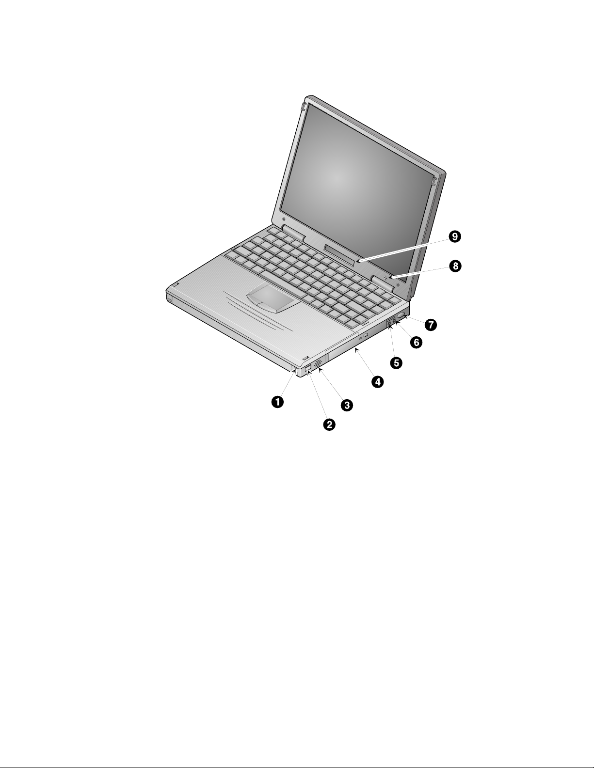
Front and Right Side Components
Component Description
Power LED
➊
Battery Charging LED
Lid Release One of two lid releases. Push in both releases at the same time
➋
Speaker Right stereo speaker used to hear sound files and system
➌
Expansion Bay Supports CD-ROM, Diskette and Optional (DVD, LS120, and
➍
➎
Microphone In
➏
Audio Out
➐
Suspend/Power Button
Internal Microphone Used to record voice, music, and sound files.
➑
Status Display Provides system operating status.
➒
The green Power LED (lower) lights when the notebook is On.
The amber Battery Charging LED (upper) lights when the
battery is charging.
to open the LCD panel.
sounds.
Hard Drive) Drive Modules.
Input connection for external microphone.
Connection for headphones or external speakers.
Turns the notebook computer On, and Suspends or Resumes
the system. Refer to the Controlling Power section of this
chapter for detailed instructions on using the Suspend/Power
button.
2-2
Page 15
Getting to Know Your Computer
Figure 2-1 Front and Right Side View
DEC01547-2
2-3
Page 16

Getting to Know Your Computer
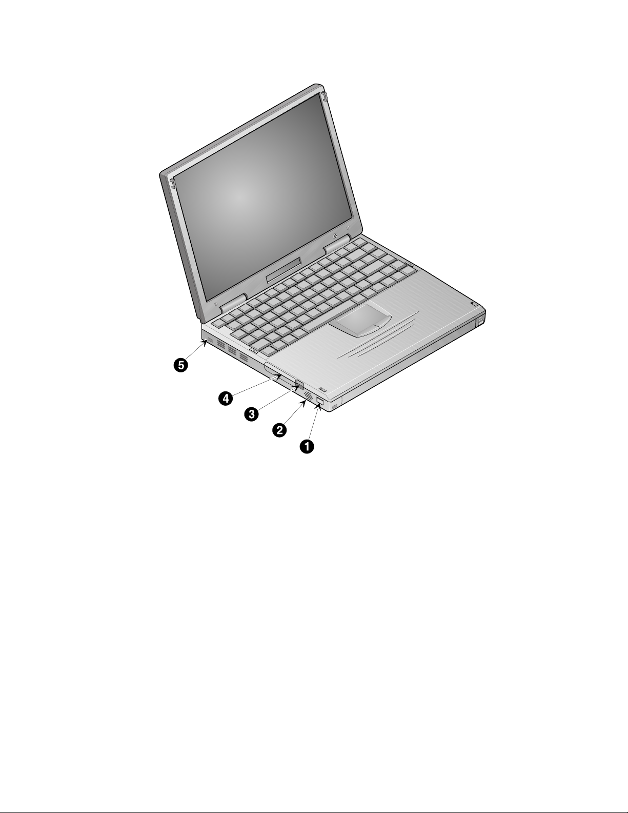
Front and Left Side Components
Component Description
Lid Release One of two lid releases. Push in both releases at the same time to
➊
Speaker Left stereo speaker used to hear sound files and system sounds.
➋
PC Card Ejectors Ejects a PC Card. Top button releases a PC Card from the top
➌
PC Card Slots Supports two Type I or Type II cards or one Type III card.
➍
Security Lock Attach a security locking device , such as a Kensington lock, to
➎
open the LCD panel.
slot; the bottom button releases a PC Card from the bottom slot.
Zoomed Video cards are supported in the bottom slot only.
this port.
2-4
Page 17
Getting to Know Your Computer
Figure 2-2 Front and Left Side View
DEC01546
2-5
Page 18
Getting to Know Your Computer
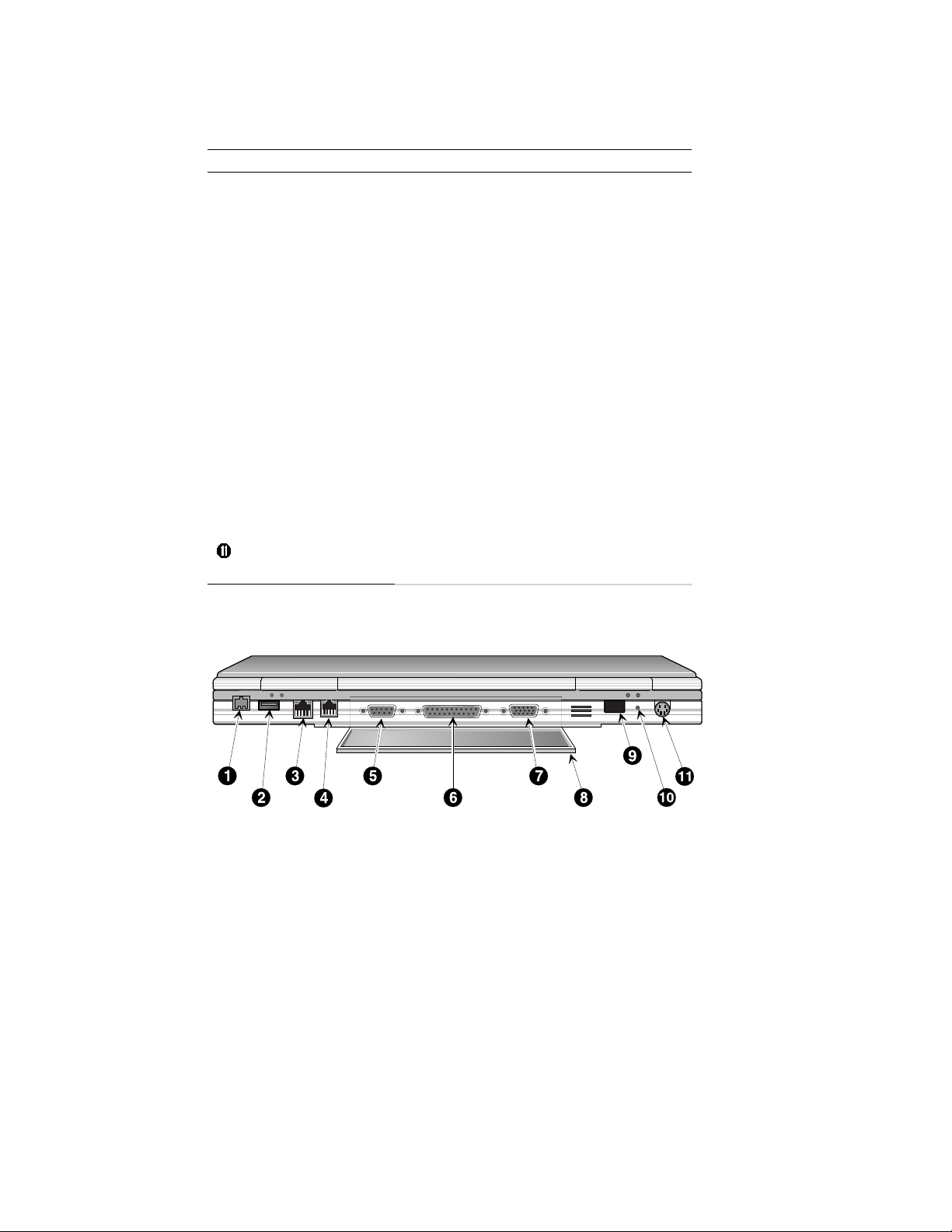
Back Components
Component Description
External Power In Input connection for Universal AC adapter.
➊
Universal Serial Bus
➋
(USB) Port
RJ45 Ethernet Network
➌
Port
RJ11 Modem Port An analog telephone line connects to this port.
➍
➎
Serial Port
➏
Parallel Port
➐
Video Port
I/O Connector Cover
➑
and Notebook Support
Fast IR Port Fast IR interface allows wireless data transfer
Ò
Ó
Reset Button
External Keyboard/
Mouse Port
A USB device, such as a mouse, keyboard, or
digital camera connects to this port.
A 10 or 100BaseT Ethernet line connects to this
port.
A serial device, such as a mouse, graphics tablet
or scanner connects to this port.
A parallel device, such as a printer, connects to
this port.
An external monitor connects to this port.
Covers I/O connectors. It can be flipped down to
support the notebook to create a comfortable
typing angle (Figure 2-6, step 4).
between the notebook and another device with an
IR interface.
Resets the notebook computer.
will be lost.
An external keyboard or PS/2 mouse connects to
this port.
All unsaved data
2-6
DEC01600
Figure 2-3 Back View
Page 19
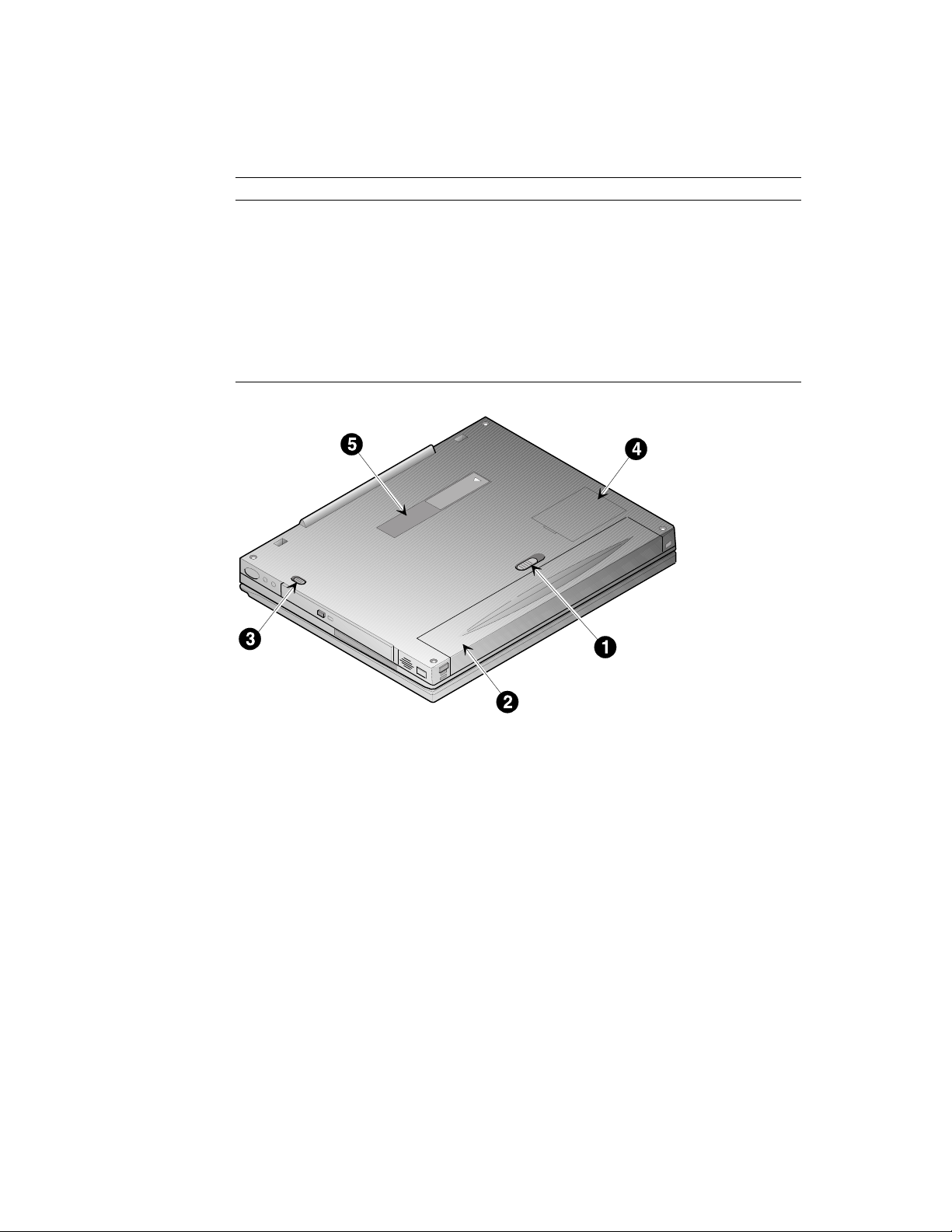
Bottom Components
Component Description
Battery Release Releases the LiIon battery from the notebook computer.
➊
LiIon Battery Provides power to your notebook computer.
➋
Expansion Bay Module
➌
Release
Memory Door Provides access to notebook computer’s memory.
➍
Docking Connector
➎
Door
Getting to Know Your Computer
Releases the drive module installed in the Expansion Bay.
Provides access to the notebook’s docking connector. This
connector is used when connecting the notebook to the Compaq
Mobile 6500 Expansion Unit or the Compaq Armada 6500
Convenience Base.
Figure 2-4 Bottom View
DEC01601
2-7
Page 20
Getting to Know Your Computer
Controlling Power
The Suspend/Power button not only enables you to take advantage of the built-in power
saving features but also turns the notebook On and Off.
Goal Action
On/Resume
Suspend
Lid Switch Close the LCD panel to place the system into Suspend mode. If the Lid
Press this button to turn the system On or resume normal operation from
the Suspend mode.
Press this button to place your system in Suspend mode.
Switch option in System Setup is set to Desktop/CRT, closing the LCD
panel will turn off the LCD screen and prevent the notebook from
entering Suspend mode. This allows the notebook to function as a
desktop computer (notebook LCD panel closed) using an external
display, keyboard, and mouse.
Off (Windows 95
and Windows NT)
fn
+
Press the [fn]+[Suspend/Power] key combination to completely shut off
your notebook from any state. If Windows is up and running, it is
recommended that you always shut down the notebook computer as
outlined in the Introducing Microsoft Windows user’s guide which was
packaged with your notebook computer.
Off (Windows 98)
fn
+
Power Button
Override
Press the [fn]+[Suspend/Power] key combination to initiate an Off
request and allow Windows 98 to shut off your notebook.
Press and hold the [Suspend/Power] button
completely shut Off your notebook computer from any state. If
Windows is up and running, it is recommended that you always shut
down the notebook computer as outlined in the Introducing Microsoft
Windows user’s guide which was packaged with your notebook
computer.
for four seconds
to
2-8
Page 21
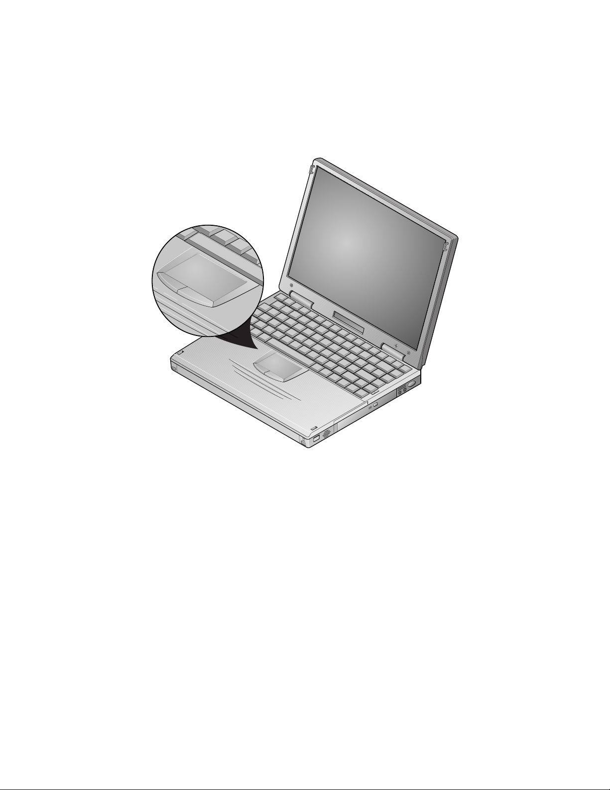
Using the Touch pad
The touch pad is a touch-sensitive pointing device that provides all the features of a mouse.
Although its operation differs from a mouse, its function is the same – to move the cursor
around the screen.
Please refer to Figure 2-5 and the following explanation on how to use the touch pad.
Getting to Know Your Computer
Figure 2-5 The Touch pad
DEC01547-3
2-9
Page 22

Getting to Know Your Computer
1. With your fingers on the keyboard in the normal typing position, the touch pad is easily
accessible by moving either your thumb or a finger down on to the touch pad.
2. Gently move your thumb or finger across the touch pad in the direction you want the
cursor to move.
3. By default, the touch pad’s left button is equivalent to the left button on a conventional
two-button mouse. The touch pad’s right button is equivalent to the right mouse button
on a conventional two-button mouse.
Single-clicking/Single-tapping
Single-clicking is a common selection technique of a conventional mouse. The touch pad’s
left and right (mouse) buttons provide the same single-clicking function. A selection
technique unique to the touch pad is single-tapping. Instead of single clicking on the left
mouse button, single-tap on the touch sensitive touch pad to make the selection. When you
tap the touch pad it is the same as clicking the touch pad’s left button.
Double-clicking/Double-tapping
The double-clicking technique found on a conventional mouse is also supported by the
touch pad’s (mouse) buttons. Another selection technique unique to the touch pad is
Double-tapping. Double-tapping allows you to select objects or execute applications.
Instead of double-clicking on the left touch pad button, double-tap on the touch sensitive
touch pad to make the selection. When you double-tap the touch pad, it is the same as
double-clicking the touch pad’s left button.
Touch Pad On-line Help
Your notebook computer’s touch pad is equipped with many advanced features. For more
detailed instructions on using and controlling the touch pad, refer to the On-line Help
provided by Synaptics. To access the On-line Help, do the following:
1. Click the TouchPad Enhancement icon located on the Windows Taskbar.
2. Then click the [Help] button.
Plugging In and Turning On
The first time you use your Compaq Armada 6500 notebook computer you should fully
charge the battery. The battery is fully charged when the Universal AC Adapter is
connected to the system and the Battery Charging LED (Figure 2-1, callout 1) is Off. Refer
to the “Power” section of the Compaq Armada 6500 HTML On-line Help for more
information on battery maintenance and use.
2-10
Page 23
Getting to Know Your Computer
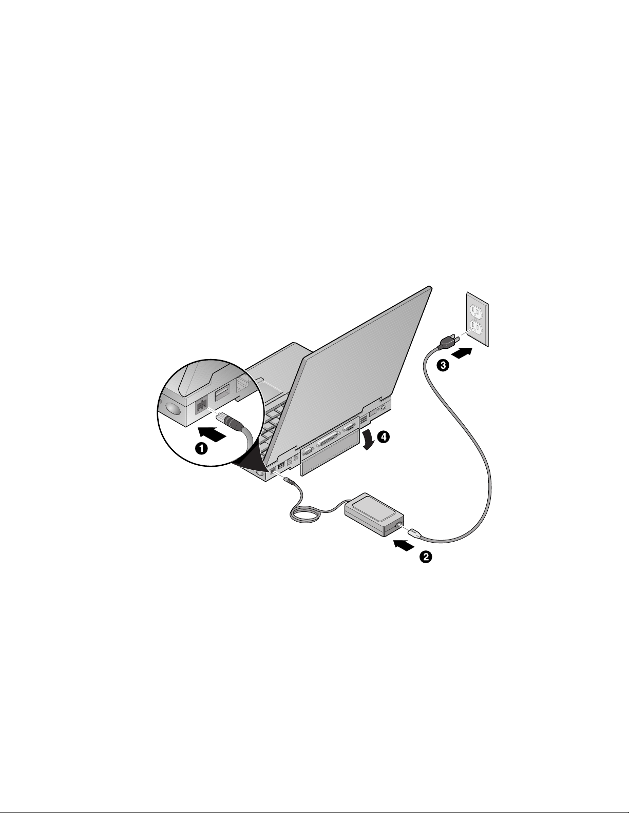
To power the notebook using the supplied Universal AC Adapter, refer to the following
instructions:
1. Connect the Universal AC Adapter cord to the External Power input port on the
notebook computer (Figure 2-6, step 1). The arrow on the connector should be on top.
2. Plug the power cord into the Universal AC Adapter (Figure 2-6, step 2).
3. Plug the power cord into a working electrical outlet (Figure 2-6, step 3).
4. Flip down the I/O connector cover to support the notebook to create a comfortable
typing angle (Figure 2-6, step 4).
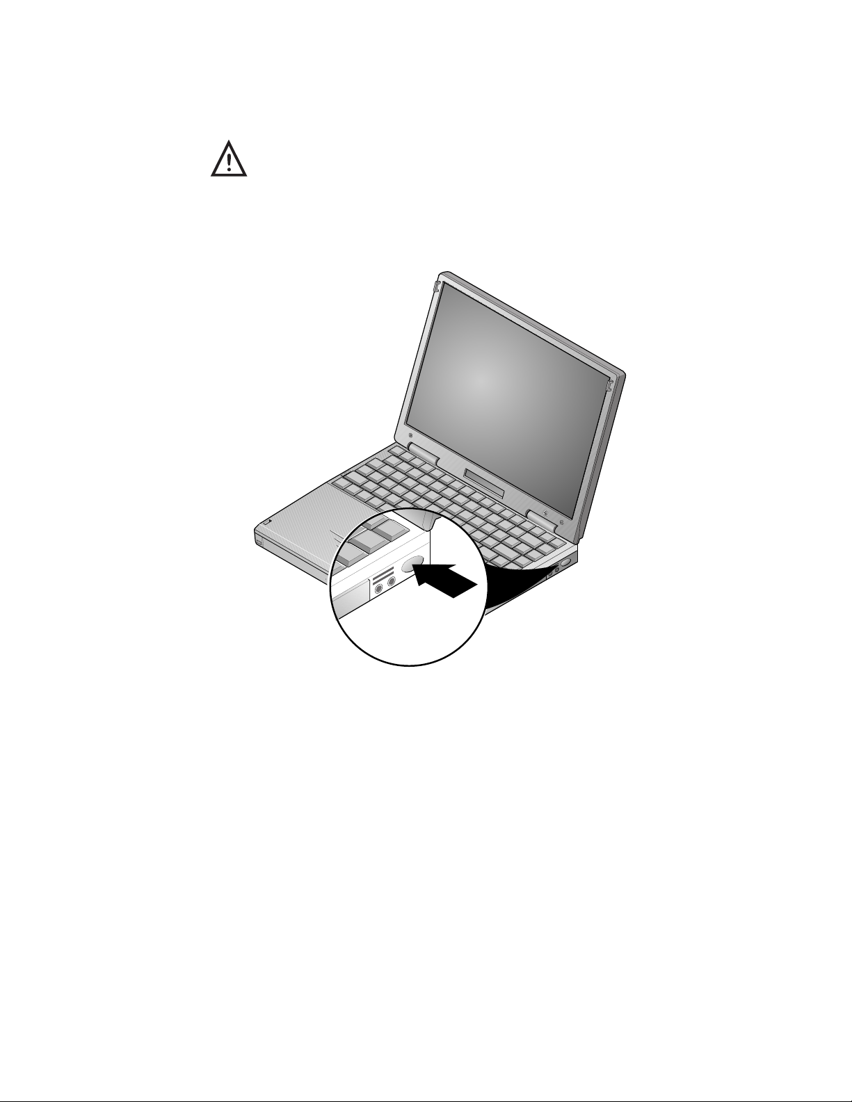
5. After you have plugged the notebook into its power source, press the Suspend/Power
button to turn the notebook computer On (Figure 2-7).
If the notebook does not power up, check the connections between the Universal AC
Adapter and the notebook computer. If the notebook computer still does not power up,
please refer to the chapter on “Troubleshooting.”
Figure 2-6 Connecting the Universal AC Adapter
DEC01602
2-11
Page 24
Getting to Know Your Computer
________________________WARNING_____________________________
Do not use an external power adapter other than the one provided by
Compaq Computer Corporation for the Compaq Armada 6500
notebook computer and options.
To avoid personal injury and/or equipment damage, do not open the
case of the power adapter. There are no customer serviceable parts.
______________________________________________________________
2-12
DEC01547-4
Figure 2-7 Turning on the Notebook Computer
Page 25

Using the Battery
Your Compaq Armada 6500 notebook computer has an easily removable main battery pack.
This section describes how to maintain and replace the notebook computer’s main battery
pack.
Preparing the Battery for Use
Your Compaq Armada 6500 notebook uses a Smart Battery. The battery has circuitry that
reports the amount of charge in the battery to the system.
Getting to Know Your Computer
Initial Use
you should:
1. Enter System Setup and disable Power Savings. Refer to Chapter 4, Configuring Your
2. Fully charge the battery.
3. Fully discharge the battery. To fully discharge the battery, use the notebook computer
4. Fully recharge the battery.
5. Enter System Setup and re-configure your power management options.
Regular Use
re-initialized by allowing the battery to go through a full charge and discharge cycle. The
frequency with which you must re-initialize the battery's circuitry is dependent on how often
you use battery power. If you use your notebook computer on battery power on a daily
basis, it is recommended to re-initialize the battery circuitry once a month.
–To properly initialize the circuitry that reports the state of the battery charge,
Notebook for detailed instructions on making System Setup configuration changes.
on battery power until the computer suspends due to low battery power. At this point
the battery is in a critically low battery state.
– The circuitry that reports the state of the battery charge must be periodically
2-13
Page 26

Getting to Know Your Computer
Battery Removal and Installation
Your Compaq Armada 6500 is equipped with a Bridge Battery that provides power for up to
four minutes when changing the notebook computer’s main battery. The addition of the
Bridge Battery means you do not have to waste valuable time powering off and rebooting
the system in order to change the main battery. Place the notebook into Suspend, remove
the drained battery and replace it with a fully charged one. Then resume normal operation.
________________________WARNING___________________________
When transporting the battery pack, make sure that the metal
terminals on the battery pack do not come in contact with other
metal surfaces (such as loose coins, paper clips, etc.). An
electrical discharge can occur which may cause injury or
damage.
____________________________________________________________
Replacing the Battery
Please refer to the following instructions and Figures 2-8a, 2-8b, 2-9a and 2-9b for detailed
instructions on changing and replacing the notebook’s main battery. To remove the battery:
2-14
1. Press the [Suspend/Power] button to place the system in Suspend mode.
__________________________ Note _____________________________
The Armada 6500 Bridge Battery provides four minutes of battery power. If the
Suspend Mode option in System Setup is set to Suspend to RAM and the main
battery is out of the system for more than four minutes without connecting the
system to external power,
option is set to Save to Disk, the main battery can be removed for an indefinite
period without loss of data.
____________________________________________________________
2. Turn the notebook computer over so the bottom of the unit is facing up.
all unsaved data will be lost
. If the Suspend Mode
Page 27
Getting to Know Your Computer
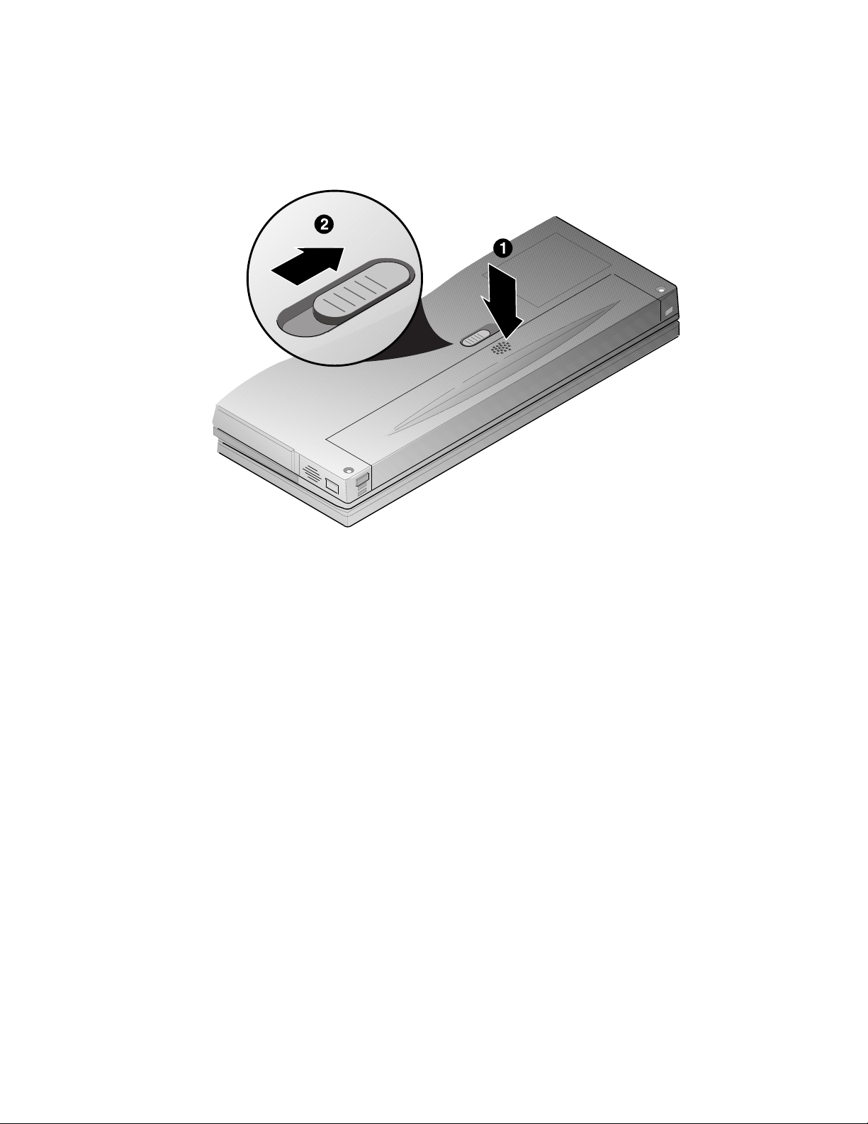
3. While depressing the battery near the latch (Figure 2-8a, step 1), slide the battery latch
to the unlock position (Figure 2-8a, step 2).
Figure 2-8a Removing Battery
DEC01667
2-15
Page 28
Getting to Know Your Computer
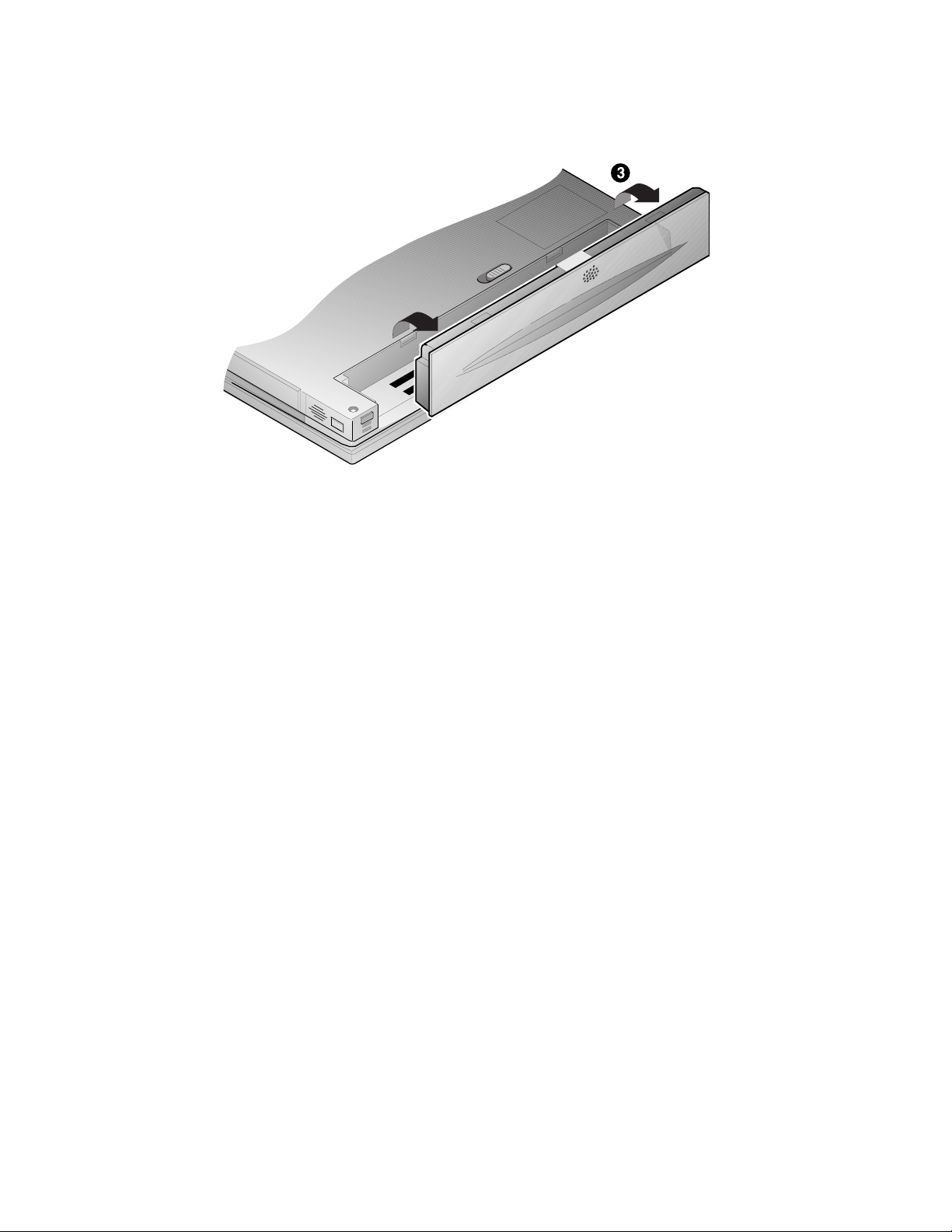
4. Lift the battery up and out of the notebook computer (Figure 2-8b, step 3).
Figure 2-8b Removing Battery
DEC01603
2-16
Page 29
Installing the Battery
To install the battery:
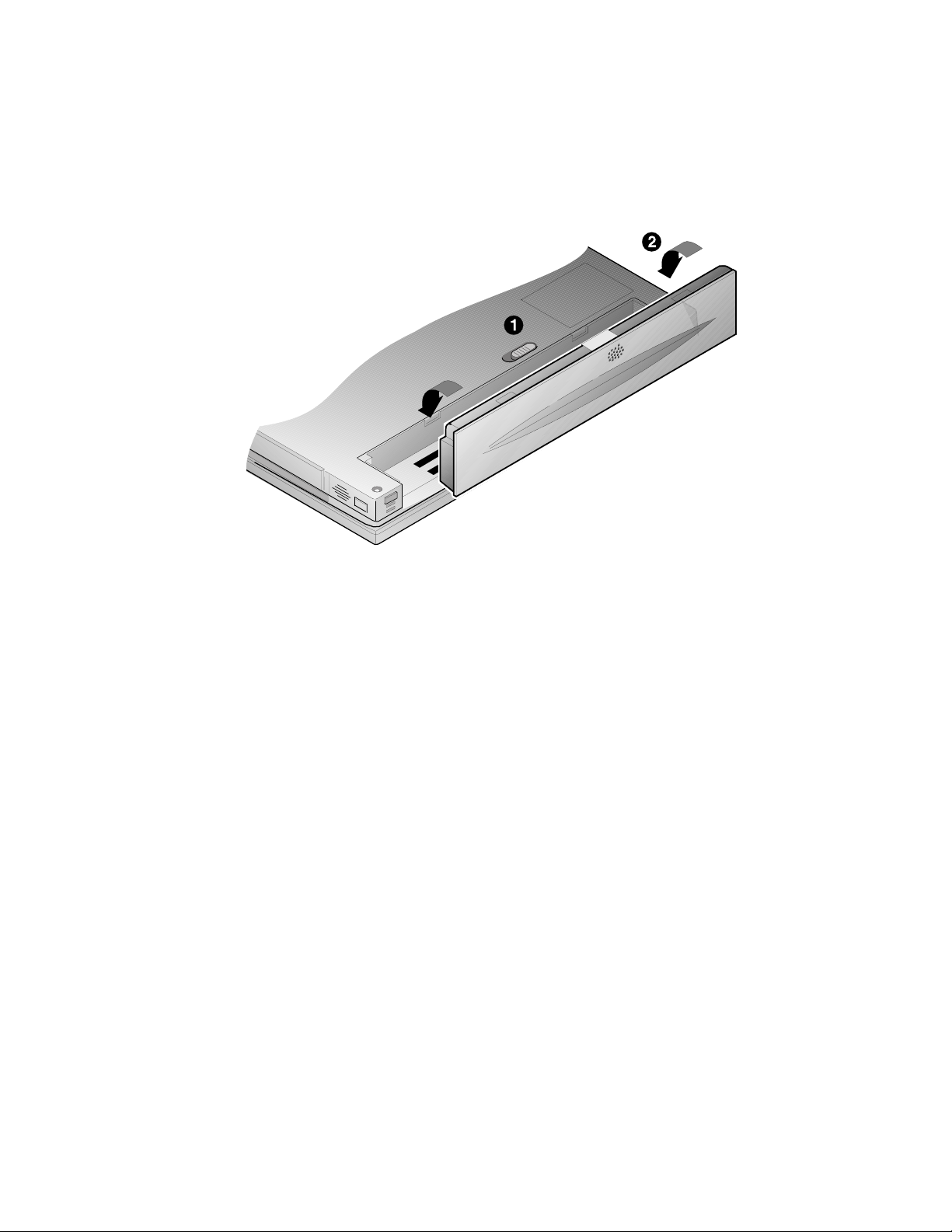
1. Verify that the battery latch is in the unlock position (Figure 2-9a, step 1).
2. Place the battery in the battery compartment (Figure 2-9a, step 2).
Getting to Know Your Computer
Figure 2-9a Installing the Battery
DEC01604
2-17
Page 30
Getting to Know Your Computer
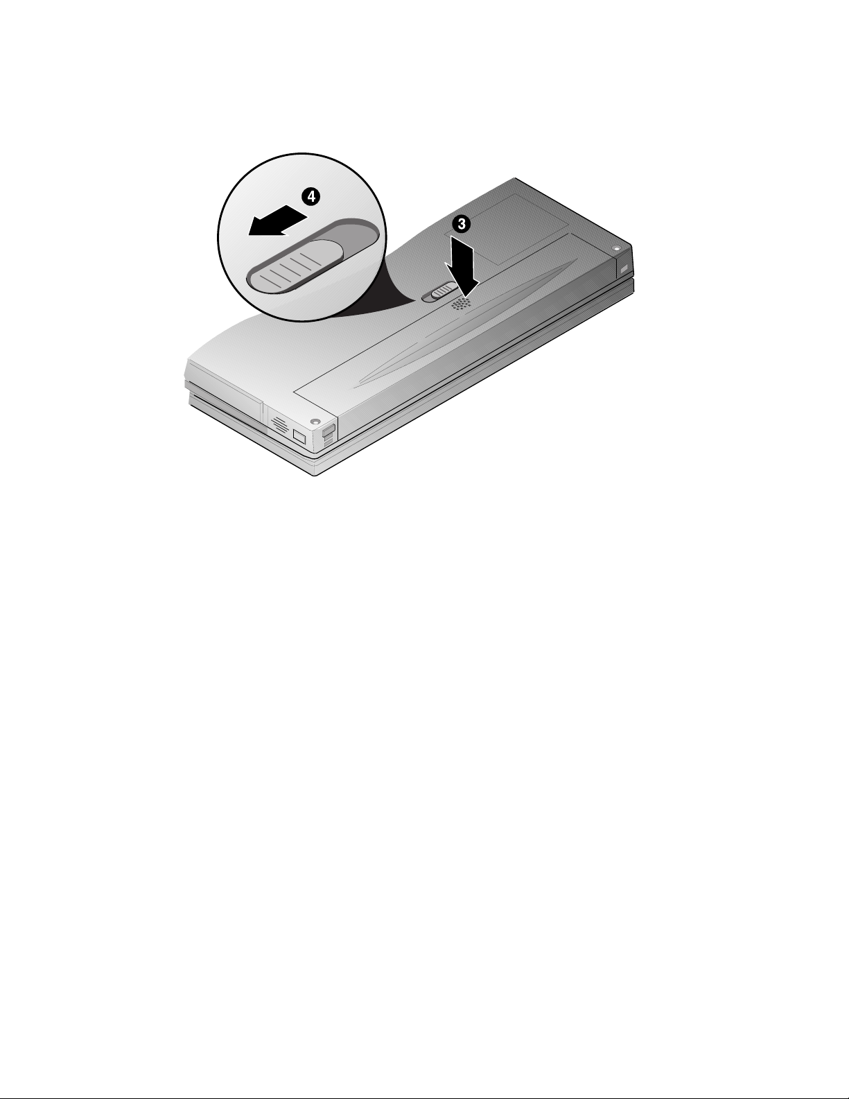
4. While pressing down on the battery near the latch (Figure 2-9b, step 3), slide the battery
latch to the lock position (Figure 2-9b, step 4).
2-18
DEC01668
Figure 2-9b Installing the Battery
Page 31

Using Your Modem
Prior to using your internal modem, you must ensure the following:
· The modem is properly configured for the country in which it will be
used via the Country Select Utility, and
· The appropriate adapter cable is supplied. A modem adapter cable is
supplied for the country in which the notebook computer was
purchased. If you wish to use the notebook’s modem in a country other
than the one in which the notebook was purchased, contact your
authorized Compaq reseller or go to www.compaq.com (search for:
Telecom Network Approvals) for more information on obtaining
country specific adapter plugs.
____________________User Responsibility ______________________
The modem installed in this system requires the user to select the correct country
profile before initiating a modem dial-up connection. The preinstalled Country
Select utility is used to ensure that your modem will operate as intended and in
compliance with national telecommunication regulations/laws. When traveling
from country to country you must use the C
the modem for a new location. Failure to do so may cause the modem to not
function properly and invalidate the approval.
____________________________________________________________
Getting to Know Your Computer
ountry Select utility
to reconfigure
Country Select Utility
The Country SelectTM utility is a Windows-based utility that enables the CreditCard Ethernet
10/100+Modem 56 user to select a “country of installation” setting for modem
communications. This setting enables the modem to function in accordance with the
configuration requirements of a specific country.
2-19
Page 32

Getting to Know Your Computer
How to Use Country Select
The Country Select utility is automatically copied to your hard drive during Windows Setup.
A Country Select icon is also installed in the Windows program group so that the utility can
be rerun if the country settings need to be changed.
Follow the steps below to run Country Select.
1. Click the [Start] button located on the Windows Taskbar, then click [Programs].
2. Double-click the Country Select icon in the CreditCard program group.
3. The current country setting is listed at the top of the screen, and the other countries
supported are listed below. To change to a different country, locate the country on the
list and double-click. The application will verify that the country setting has been
changed.
4. Click on Exit to close the program.
More Information
Your notebook computer features an integrated Xircom CreditCard Ethernet 10/100 +
Modem 56 PC Card. For more information on using and troubleshooting the CreditCard
Ethernet 10/100 + Modem 56, visit the Xircom web site at: http://www.xircom.com
2-20
Page 33

System Software & Restoration
This chapter provides an overview of the applications and utilities supplied on the Compaq
Software CD as well as directions on how to restore your system using the Compaq
QuickRestore CD.
Installing Optional Software
The Compaq Software CD contains on-line documentation, applications, utilities, and
drivers for the notebook computer. The Software CD has a menu driven program making it
easy to install and access the applications and information. After you complete Windows
Setup, you will want to do the following:
· Run the Software CD’s Installation Program.
· Install the on-line documentation, found in the Documentation menu on the CD.
· Install the desired applications, found in the Applications menu on the CD.
3
3-1
Page 34

System Software & Restoration
Application Description
The following details the applications available on your Compaq Software CD and provides
an explanation of each.
Software Title Software Description
Adobe Acrobat Reader
3.1
Puma IntelliSync97 IntelliSync97 for Windows is a powerful notebook-to-notebook or
ESS Audio Rack32 AudioRack allows you to playback, record, mix and edit sound
Smithmicro QuickLink
III
Acrobat Reader allows you to view .PDF user documentation files
provided on the Compaq Software CD.
notebook-to-PC software solution that allows you to synchronize
all your data. IntelliSync97 provides file transfer as well as file
and PIM (personal information manager) synchronization between
your Armada 6500 and another notebook via infrared port, parallel
port or serial port. If you plan to use the infrared port, you must
enter System Setup and enable the Infra-Red Port prior to installing
IntelliSync97. See Chapter 4, “Configuring Your Notebook” for
detailed System Setup information.
files.
QuickLink III is a powerful application that provides fax sending
and receiving, and data transfer capabilities. Note that this
software is provided for use with your internal Xircom modem
(standard device on selected models) only and may or may not
support modems from other vendors.
Installing Documentation and Applications
To install software from the Compaq Software CD:
1. Install the CD-ROM Drive module in the notebook computer.
2. Place the Compaq Software CD in the CD-ROM drive (label side up).
3. Click on the [Start] button located on the Windows Task bar, then click [Run].
4. In the open field, type: X:\CDINSTALL (where X represents the drive letter assigned to
your CD-ROM) and click [OK].
5. When the Welcome screen appears, click [Next]. The Choose Desired Category
window will appear. Follow the on-screen instructions to install the desired documents
and applications.
3-2
Page 35

Utilities
The following details the utilities available on your Compaq Software CD and provides
explanation of each.
Utilities Utility Description
Make Boot Diskettes This utility allows you to create a bootable diskette set. The Boot
AMI Diagnostics AMI Diagnostics is designed to help isolate hardware failures and
Japanese 3-mode
Support (Windows 95
only)
Make Boot Diskettes
To create a Boot Diskette Set:
System Software & Restoration
Diskette set allows you to boot directly to DOS. It provides a
menu-driven interface offering options to partition and format the
hard drive or run the AMI Diagnostics utility.
identify important system configuration information prior to
requesting on-site service, or returning your computer to a service
center for repair. In addition to being able to run AMI Diagnostics
from the Compaq Software CD, the AMI Diagnostics utility can
also be run from the bootable diskette set created via the Make
Boot Diskettes utility mentioned above. See “Using Diagnostics”
for detailed information on using AMI Diagnostics.
This option provides the necessary drivers to support 1.25MB
floppy diskettes which are common in the Japanese marketplace.
__________________________ Note_____________________________
Before creating the Boot Diskette Set, obtain two blank formatted floppy
diskettes.
____________________________________________________________
1. Boot to Windows, then insert the Compaq Software CD into the CD-ROM Drive.
2. Select the [Start] button located on the Windows Taskbar, then click on [Run]. In the
Open field, type: X:\CDINSTALL (where X represents the drive letter assigned to your
CD-ROM) and click [OK].
3. When the Welcome screen appears, click [Next]. The Choose Desired Category screen
will appear. Click on the Utilities radio button and then click [Next].
4. The Utilities screen will appear. Click on the Make Boot Diskettes radio button and
click [Install].
5. You will be informed that two formatted diskettes are required to complete this process.
Obtain two formatted diskettes, then click [Yes] to continue the process.
3-3
Page 36

System Software & Restoration
6. The program will prompt you to remove your CD-ROM Drive and insert the Floppy
Drive. The CD-ROM and Floppy Drives are hot swappable; there is no need to power
down the notebook before swapping drives. Replace the drive now. There will be a
short delay as system the recognizes the new drive. When touch pad/mouse
functionality returns, insert the first formatted diskette and click [OK].
7. When prompted to insert a second formatted diskette, remove the diskette 1 and label it
Armada Boot Diskette 1. Then insert the second diskette and click [OK].
8. When complete remove the second diskette and label it Armada Boot Diskette 2. Write
protect both diskettes.
AMI Diagnostics
Both Windows 95 and Windows NT users receive AMI Diagnostics, a DOS-based
diagnostic utility, found on the Compaq Software CD. AMI Diagnostics is designed to help
isolate hardware failures and identify important system configuration information prior to
requesting on-site service, or returning your computer to a service center for repair. In
addition to being able to run AMI Diagnostics from the Compaq Software CD, the AMI
Diagnostics utility can as be run from the bootable diskette set created via the Make Boot
Diskettes utility.
Using AMI Diagnostics on CD
In the event of a hardware failure, your system can be booted from the Compaq Software
CD. The AMI Diagnostics can then be used to examine the computer’s current
configuration, locate faulty components, and troubleshoot problems. If your system fails to
boot, proceed as follows:
3-4
1. Insert the Compaq Software CD into the CD-ROM Drive and power on the notebook.
Enter the System Setup Program by pressing [fn]+[F3] key combination when the
Compaq logo appears.
2. Ensure that the Power Savings option on the Power menu is set to Disabled. Also ensure
that ATAPI CD-ROM is the first entry in the boot priority list found on the Boot menu.
Then select the Exit Saving Changes option found on the Exit menu. The notebook will
automatically reboot. Refer to Chapter 4, “Configuring Your Notebook” for more
information on making configuration changes in System Setup.
3. When the Compaq Armada Boot CD screen appears, press [Y] to proceed. The Armada
Boot CD menu will appear.
[1] FDISK to partition your Hard Drive
[2] Format your Hard Drive
[3] Run AMI System Diagnostics
[4] Quit
Page 37

System Software & Restoration
4. Choose option [3] Run AMI System Diagnostics.
5. You will be informed that the AMI Diag Program files will be extracted to a RAM drive
and that the process will take approximately one minute. Press [Y] to proceed.
6. The utility will detect your system hardware configuration and extract the required
compressed diagnostics files into RAM drive. Upon file de-compression the main menu
will be displayed. Use the UP and DOWN arrow keys to scroll to the desired selection:
or simply press the key corresponding to the first letter of the menu item. Compaq
recommends that you first view the HELP FILE for more information on using the
diagnostics and for the latest release notes.
7. At the end of each diagnostic run, you will be notified if the test ran successfully or if
errors were encountered. If errors were encountered, you will be given a choice to view
the error log file to determine the nature of the problem encountered by the diagnostic.
All test results are written to a file named AMIDIAG.LOG. This file can be viewed by
selecting the Display Error Log File option from the Options menu.
__________________________ Note_____________________________
The AMIDIAG.LOG file is saved to RAM drive by default. In this condition, if
you power down, the AMIDIAG.LOG file will be lost. If you want to save the
AMIDIAG.LOG file, exist to DOS and manually copy it to the diskette or hard
drive. You may also save the AMIDIAG.LOG file from the Options menu
Generate Report selection.
____________________________________________________________
3-5
Page 38

System Software & Restoration
Using AMI Diagnostics on Diskette
AMI Diagnostics can also be run from the Boot Diskette Set created in Creating a Boot
Diskette Set. If you would prefer to run AMI Diagnostics from diskette instead of CD,
create a Boot Diskette Set now. To run AMI Diagnostics from diskette:
1. Insert Armada Boot Diskette 1 into the Floppy Drive and power on the notebook. Enter
the System Setup Program by pressing [fn]+[F3] key combination when the Compaq
logo appears.
2. Ensure that the Power Savings option on the Power menu is set to Disabled. Also ensure
that Diskette Drive is the first entry in the boot priority list found on the Boot menu.
Then select the Exit Saving Changes option found on the Exit menu. The notebook will
automatically reboot. Refer to Chapter 4, “Configuring Your Notebook” for more
information on making configuration changes in System Setup.
3. When the Compaq Armada Boot Floppy screen appears, press [Y] to proceed. The
Armada Boot Floppy menu will appear.
[1] FDISK to partition your Hard Drive
[2] Format your Hard Drive
[3] Run AMI System Diagnostics
[4] Quit
4. Choose option [3] Run AMI System Diagnostics.
3-6
5. You will be informed that the AMI Diag Program files will be extracted to a RAM drive
and that the process will take approximately one minute. Press [Y] to proceed.
6. When prompted remove Armada Boot Diskette 1 from the Floppy Drive and insert
Armada Boot Diskette 2. Then press any key to continue. The utility will detect your
system hardware configuration and extract the required compressed diagnostics files
into RAM drive. Upon file de-compression the main menu will be displayed. Use the
UP and DOWN arrow keys to scroll to the desired selection: or simply press the key
corresponding to the first letter of the menu item. Compaq recommends that you first
view the HELP FILE for more information on using the diagnostics and for the latest
release notes.
Page 39

7. At the end of each diagnostic run, you will be notified if the test ran successfully or if
errors were encountered. If errors were encountered, you will be given a choice to view
the error log file to determine the nature of the problem encountered by the diagnostic.
All test results are written to a file named AMIDIAG.LOG. This file can be viewed by
selecting the Display Error Log File option from the Options menu.
__________________________ Note_____________________________
The AMIDIAG.LOG file is saved to RAM drive by default. In this condition, if
you power down, the AMIDIAG.LOG file will be lost. If you want to save the
AMIDIAG.LOG file, exist to DOS and manually copy it to the diskette or hard
drive. You may also save the AMIDIAG.LOG file from the Options menu
Generate Report selection.
____________________________________________________________
Using the Compaq QuickRestore CD
This QuickRestore CD allows you to fully restore your system to its original software
configuration as shipped from Compaq. To complete the QuickRestore process, you must
make System Setup configuration changes to the Power, Boot and Exit menu options. Refer
to Chapter 4, Configuring Your Notebook Computer for detailed instructions.
System Software & Restoration
__________________________ Note_____________________________
The QuickRestore process will format your C: drive automatically.
residing on your C: drive will be erased.
process, backup all pertinent data onto another drive (your D: or E: drive if
available) or alternate media. If you have a Windows NT 4.0 NTFS partition,
backup all pertinent data to alternate media. The QuickRestore process requires
you to delete all NTFS partitions.
____________________________________________________________
QuickRestore Preparation
1. Power off the System. Insert the CD-ROM Drive module into the Expansion Bay.
2. Boot the system and when the Compaq logo appears press the [fn]+[F3] key
combination to enter the System Setup Program.
3. Load factory default settings, then disable the Power Savings option in the Power menu
and set ATAPI CD-ROM option as the first device in the Boot Priority list found in the
Boot menu. Then choose Exit Saving Changes found in the Exit menu to exit System
Setup. Please refer to Chapter 4 for detailed System Setup instructions.
All data
Prior to beginning the QuickRestore
3-7
Page 40

System Software & Restoration
QuickRestore Procedures
Before using the Compaq QuickRestore CD to restore the factory installed software on a
new hard drive or a non-Windows 95/98 formatted hard drive, you must first complete steps
1 through 13. If you are using the Compaq QuickRestore CD to restore the factory installed
software on a hard drive formatted for Windows 95/98, proceed to step 14.
________________________ CAUTION ___________________________
Be sure that you have copied or transferred all pertinent data to
another drive or media.
____________________________________________________________
1. Insert the QuickRestore CD.
2. Boot your system. The system will automatically boot to the QuickRestore CD.
3. When the QuickRestore CD Startup Menu appears, select the desired language to view
the QuickRestore instructions if prompted (English is default). This has no impact on
the Operating System language to be installed.
4. The QuickRestore menu will appear. Choose option [1].
1) Run FDISK to partition your hard drive
2) Restore the system using the QuickRestore CD
3) Exit to DOS
3-8
5. A screen will appear stating that the entire contents of the drive will be lost. Choose [Y]
to continue.
6. When prompted whether or not to enable large disk support, choose [Y]. This applies to
both Windows 95/98 and Windows NT 4.0 users alike.
________________ Note for Windows NT Users ___________________
This partition will be converted to NTFS during Windows NT 4.0 Setup.
____________________________________________________________
Page 41

System Software & Restoration
7. The FDISK menu will appear. If using QuickRestore on a non-Windows 95/98
formatted hard drive, choose option [3]. If using QuickRestore on new hard drive,
proceed to step 9.
1) Create DOS partition or Logical DOS Drive
2) Set active partition
3) Delete partition or Logical DOS Drive
4) Display partition information
8. A Delete menu will appear. Choose option [4] to delete a non-DOS partition. FDISK
will delete the existing partitions and return you the FDISK Options menu.
9. Choose option [1] Create DOS partition or Logical DOS Drive.
10. A Create menu will appear. Choose option [1] Create Primary DOS Partition. FDISK
will verify the drive’s integrity then prompt you whether or not you wish to use the
maximum available size for a primary DOS partition and make the partition active.
Choose [Y]. When complete FDISK informs you that a primary DOS partition has been
created and returns you to the FDISK Options menu.
__________________________ Note_____________________________
If you choose to configure the size of the partition yourself, ensure that it is at
least 512 megabytes. If you are unsure of the size you need, choose the default.
____________________________________________________________
11. Press [ESC] to exit FDISK. When prompted to restart the system, press [ESC].
12. One again you will be prompted to reboot the system, press [ctrl]+[alt]+[del] to reboot
the system.
13. Proceed to step 15.
14. Insert the Compaq QuickRestore CD into the CD-ROM drive and reboot the system.
The system will automatically boot to the QuickRestore CD.
15. When the QuickRestore CD Startup Menu appears, select the desired language to view
the QuickRestore instructions if prompted (English is default). This has no impact on
the Operating system language to be installed.
3-9
Page 42

System Software & Restoration
16. Choose the option [2] Restore your system using the QuickRestore CD. You will be
prompted whether or not to continue the Restore process. Press [ctrl]+[c] at any prompt
to exit this process or press the space bar to continue. After the last question, the
system will format and copy the system files onto your Drive C:.
________________________ CAUTION ___________________________
not
Do
press any keys beyond this point. Pressing certain keys may
cause QuickRestore failure.
____________________________________________________________
17. When prompted, remove the QuickRestore CD from the CD-ROM drive and press
[ctrl]+[alt]+[del] to reboot your system.
18. The system will boot to the C: drive. Follow the on-screen instructions to install
Windows as usual.
3-10
Page 43

Configuring Your Notebook
This chapter provides information on how to configure your notebook computer and its
security features using the System Setup Program. Your notebook computer is configured
with default settings selected for typical notebook computer use.
If you are familiar with System Setup programs, refer to the appropriate sections in this
chapter for information on configuring or updating your notebook computer. Otherwise,
carefully read this chapter before attempting to modify your notebook computer’s
configuration and security settings.
Here are some instances when you might want to change your computer’s System Setup.
You might need to:
· Change the date and time
· Change your computer’s security level
· Enable/disable and configure power management
Running System Setup
The System Setup Program enables you to select and store information about the notebook
computer’s hardware configuration, boot sequence, security, and power management
features. This information is stored in the computer’s battery backed-up CMOS RAM.
4
System Setup Utility
To run System Setup:
1. Turn on or reboot your notebook computer.
2. During system boot, press the [fn] + [F3] key combination when the Compaq logo
appears. When the logo appears you have approximately 4 seconds to enter System
Setup.
4-1
Page 44

Configuring Your Notebook
Updating Your Notebook Computer's Configuration
There are a number of hardware features that can be configured on your notebook computer.
Menu Configurable Features
Main System Time
Advanced Secured Setup Configurations
Security Set Supervisor Password
Power Power Savings
Boot Summary Screen
Exit Exit Saving Changes
System Date
Lid Switch Mode
I/O Device Configuration
Reset Configuration Data
Large Disk Access Mode
SMART Device Monitoring
TV Format
Set User Password
Password on boot
Password on resume
Password on undock
Fixed disk boot sector
Standby Timeout
Auto Suspend Timeout
Suspend Mode
Hard Disk Timeout
Video Timeout
Cooling Mode
Resume On Time
Resume Time
Resume Date
Quick Boot Mode
Boot Device Priority
Exit Discarding Changes
Load Setup Defaults
Discard Changes
Save Custom Defaults
Load Custom Defaults
Save Changes
4-2
Page 45

Helpful Hints
There are several keyboard keys assigned to help you select menus and sub-menus, options,
and to change option values.
Legend Key Alternate Key Function
F1 Alt + H Displays the General Help window.
ESC Alt + X Exits the current menu and returns you to the previous
¬
or
-
¯
or
F5
F6
F9 Sets the fields for the active menu to their default values.
F10 Saves the new configuration and exits the System Setup.
Press Enter Executes commands, selects submenus, selects fields, or
®
Configuring Your Notebook
screen.
Selects a different menu bar item.
Moves the cursor up and down between fields.
(minus key) Scrolls backwards through the values of the highlighted
-
+ (plus key)
<space bar>
field.
Scrolls forward through the values of the highlighted
field.
displays available options.
Launching Submenus
Notice that a pointer symbol appears next to selected fields in the menu screens. For
example, see the I/O Device Configuration option in the Advanced menu. The symbol
indicates the existence of a submenu that can be launched for more advanced configuration
options. To launch a submenu:
1. Move the highlighted cell to the desired Menu Bar item and press <Enter>.
2. Use the legend keys to navigate around the screen and make the needed configuration
changes.
3. When you finish, press the [esc] key to exit the submenu and return to the main screen.
4-3
Page 46

Configuring Your Notebook
Main Menu
Feature Settings Comments
System Time Enter current time:
System Date Enter current date:
Diskette Display only field Indicates the notebook is configured to support a
Lid Switch Suspend/Resume*
Primary Master Display only field Description of hard drive.
Primary Slave Display only field Description of IDE device installed in the
Secondary
Master
System Memory Display only field Indicates the amount of conventional memory
Extended
Memory
System BIOS
version
Keyboard BIOS
version
*Factory default setting
hour, minute, second
format.
month, day, year
format.
Desktop/CRT
Display only field Description of IDE device installed in Compaq
Display only field Indicates the amount of RAM, minus
Display only field Indicates the current System BIOS version.
Display only field Indicates the current Keyboard BIOS version.
Sets the system to specified time.
Sets the system to specified date.
1.44/1.25MB 3 ½ " floppy drive.
This option allows you to configure the way the
notebook computer responds when opening and
closing the LCD display panel. When
Suspend/Resume is selected, the system enters
Suspend Mode when the lid is closed and
Resumes operation when the lid is opened. When
Desktop/CRT mode is selected, the external video
port is enabled when the lid is closed.
notebook’s Expansion Bay.
Mobile 6500 Expansion Unit.
used by the system.
conventional memory (640KB) and high memory
(360KB), installed in the system.
4-4
Page 47

Advanced Menu
Field Settings Comments
Secured Setup
Configurations
I\O Device
Configuration
Reset
Configuration
Data
Large Disk
Access Mode
SMART Device
Monitoring
TV Format Selected Formats This option allows you to specify the video output
*Factory default setting
Configuring Your Notebook
No*
Yes
Submenu Peripheral Device Configuration: Refer to I/O
No*
Yes
Other
DOS*
Disabled
Enabled*
Select Yes to prevent a Plug and Play Operating
System from changing system settings.
Device Configuration Submenu for a description of
the available settings.
Select Yes to clear all Plug and Play configuration
information stored in Extended System
Configuration Data non-volatile RAM.
Select Other if a non-Microsoft operating system is
installed on your system. If you install new software
and the drive fails, change this selection and try
again. Different operating systems require different
representations of drive geometries.
Enables/Disables IDE Failure Prediction.
format supported by your country when using the
video ports provided on the Mobile 6500 Expansion
Unit.
I\O Device Configuration Submenu
Field Settings Comments
Floppy disk
controller
*Factory default setting
Disabled
Enabled*
Auto
Disables the onboard Floppy Disk Controller.
Enables the onboard Floppy Disk Controller.
Allows the BIOS or O/S to automatically configure
the Floppy Disk Controller.
Continued
4-5
Page 48

Configuring Your Notebook
Continued
Field Settings Comments
Serial Port Disabled
Enabled
Auto*
Infra-Red Port Disabled
Enabled
Auto*
Parallel Port Disabled
Enabled
Auto*
Parallel Port
Mode
*Factory default setting
Output only
Bi-directional*
ECP (Extended
Capabilities Port)
EPP (Enhanced
Parallel Port)
Disables the onboard Serial Port.
Enables and allows you to manually configure the
I/O address and Interrupt Request (IRQ) line for the
Serial Port.
Enables and automatically configures the Serial
Port.
Disables the onboard Infrared Port.
Enables and allows you to manually configure the
operating mode, I/O address and Interrupt Request
(IRQ) line, and DMA channel for the Infrared Port.
Enables and automatically configures the Infrared
Port. You must manually configure the operating
mode.
Disables the onboard Parallel Port.
Enables and allows you to manually configure I/O
address, Interrupt Request (IRQ) line and DMA
channel (if ECP is selected for Parallel Port Mode)
for the Infrared Port.
Enables and automatically configures the Parallel
Port.
Select the mode supported by your printer. See
your printer’s User Guide for details.
4-6
__________________________ Note _____________________________
It is highly recommended that you use the Auto configure setting. If you need to
manually configure a device, it is recommended that you use the “System”
application located in the Windows “Control Panel.”
____________________________________________________________
Page 49

Security Menu
Feature Settings Comments
Supervisor
Password Is
User Password Is Display only field. When set to Clear, a User Password has not
Set Supervisor
Password
Set User Password Enter a password of
Password on Boot Disabled*
Password on
Resume
Password on
Undock
Fixed disk boot
sector
*Factory default setting
Configuring Your Notebook
Display only field. When set to Clear, a Supervisor Password has
Enter a password of
up to eight
alphanumeric
characters. Password
is not case sensitive.
up to eight
alphanumeric
characters. Password
is not case sensitive.
Enabled
Disabled*
Enabled
Disabled*
Enabled
Normal*
Write Protect
not been set.
been set.
This option allows you to set a Supervisor
Password that will be required to enter the
System Setup. This password can be used in
place of the User Password.
Caution:
and store it in a safe place.
This option allows you to set a User Password
that will be required during: System Setup
access and System Boot, Resume, and Undock
operations if enabled.
Caution:
and store it in a safe place.
When set to Enabled, you will be prompted for
a password on each system boot. A User
Password must be set in order to access this
feature.
When set to Enabled, you will be prompted for
a password each time the system resumes
operation from Suspend Mode. A User
Password must be set in order to access this
feature.
This option allows you to enable a password to
prevent unauthorized undocking of the
notebook computer from the Armada 6500
Convenience Base or Mobile 6500 Expansion
Unit. When a User Password is set and this
option is set to Enabled, the notebook cannot be
undocked unless the system is powered on and
the User or Supervisor Password is supplied.
Set this option to Write Protect to protect the
hard disk boot sector from virus infection.
Be sure to write the password down
Be sure to write the password down
4-7
Page 50

Configuring Your Notebook
Notebook Computer Security
Notebook Computer Security is important to avoid theft or accidental loss of your computer
software and hardware. The Compaq Armada 6500 provides the following levels of
protection:
· User Password – Used to prevent unauthorized access to your notebook computer and
prevent unauthorized removal of the notebook from a docking option. The User
Password also allows access to a subset of the System Setup options.
· Supervisor Password – Used to prevent unauthorized access to your notebook
computer’s System Setup.
· Password on Undock – Used to prevent unauthorized undocking of the notebook from
the Armada 6500 Convenience Base or Mobile 6500 Expansion Unit. Requires a User
Password be set.
_________________________Caution____________________________
It is important that you remember your User and Supervisor Password
after you have set them on your notebook computer. If you forget
either password and want to have it reset, you must send the notebook
computer along with proof of ownership to a Compaq Service Center
for service.
____________________________________________________________
Setting/Changing a Supervisor Password
If you set a Supervisor Password, you need to enter it each time you want to access the
System Setup. Perform the following steps to set or change the Supervisor Password:
__________________________ Note _____________________________
The Supervisor Password can be used in place of the User Password.
____________________________________________________________
1. Turn on your notebook computer.
2. During system boot, press the [fn] + [F3] key combination when the Compaq logo
appears to enter System Setup.
3. If a Supervisor Password is set, enter the Supervisor Password when prompted.
The System Setup main menu will appear on the screen.
4. Highlight the Security menu option.
5. Highlight the Set Supervisor Password field and press [Enter].
4-8
Page 51

Configuring Your Notebook
6. Type in your password and press [Enter]. The password can be up to eight
alphanumeric characters and is not case sensitive. Symbols and other keys are ignored.
To confirm, type in your Supervisor Password a second time and press [Enter].
__________________________ Note_____________________________
If a password already exists, you will be prompted to enter the old password
before a new one can be set.
____________________________________________________________
7. When the Notice dialog box appears notifying you that changes have been saved, press
[Enter].
8. Select the Exit menu and choose Exit Saving Changes to save your new settings and
exit System Setup.
When you access System Setup, will be prompted for the Supervisor Password.
__________________________ Note_____________________________
Passwords take effect immediately upon confirmation. The password will remain
in effect if you exit the System Setup Program without saving the new
configuration settings.
____________________________________________________________
Setting/Changing a User Password
The User Password prevents unauthorized access to your notebook computer and
unauthorized removal of the notebook from a docking option. It also allows access to a
subset of the System Setup option. Perform the following steps to set or change the User
Password:
1. Turn on your notebook computer.
2. During system boot, press the [fn] + [F3] key combination when the Compaq logo
appears to enter System Setup.
3. If a User Password is set, enter the User Password when prompted.
4. Highlight the Security menu.
5. Highlight the Set User Password field and press [Enter].
6. Type in your password and press [Enter]. The password can be up to eight
alphanumeric characters and is not case sensitive. Symbols and other keys are ignored.
To confirm, type in your User Password a second time and press [Enter].
4-9
Page 52

Configuring Your Notebook
__________________________ Note _____________________________
If a password already exists, you will be prompted to enter the old password
before a new one can be set.
____________________________________________________________
7. When the Notice dialog box appears notifying you that changes have been saved, press
[Enter].
8. Select the Exit menu and choose Exit Saving Changes to save your new settings and
exit System Setup.
__________________________ Note _____________________________
Passwords take effect immediately upon confirmation. The password will remain
in effect if you exit the System Setup Program without saving the new
configuration settings.
____________________________________________________________
Deleting a Supervisor or User Password
To delete a Supervisor or User Password:
1. Turn on your notebook computer.
4-10
2. During system boot, press the [fn] + [F3] key combination when the Compaq logo
appears to enter System Setup.
3. When prompted, enter the password to be deleted.
4. Highlight the Security menu.
5. If deleting the Supervisor Password, highlight the Set Supervisor Password field and
press [Enter]. If deleting the User Password, highlight the Set User Password field and
press [Enter].
6. When prompted enter the old password.
7. With the cursor in the “Enter new password” field, press [Enter].
8. The cursor will move to the “Re-enter new password” field. Press [Enter].
9. When the Notice dialog box appears notifying you that changes have been saved, press
[Enter].
10. Select the Exit menu and choose Exit Saving Changes to save your new settings and
exit System Setup.
Page 53

Password on Undock
Setting a User Password and enabling Password on Undock prevents unauthorized
undocking of the notebook from the Compaq Mobile 6500 Expansion Unit and/or the
Compaq Armada 6500 Convenience Base. When a request is made to undock the notebook,
you will be prompted for a password. Enter either the Supervisor or User Password to
complete the undock request and undock the notebook.
Power Menu
Your notebook computer is factory-configured with preset power management values. If
you are not an advanced user, start by using the default (factory-configured) power
management settings. If you find that the factory settings do not fit your specific needs,
enter the System Setup Program and make the needed changes.
Feature Settings Comments
Power Savings Disabled
Standby Timeout Off
Customized*
Maximum Power
Savings
Maximum
Performance
Selected times
Configuring Your Notebook
Disables all power management features.
Allows you to customize the power
management features to meet your unique
operating needs.
Use Maximum Power Savings when you want
to maximize the time between battery charges.
Use Maximum Performance when you want to
maximize the performance of your notebook
while retaining some power savings for
extending the life of the battery.
This option allows you to specify a period of
time the system must be inactive before the
system is placed in Standby mode.
Standby mode shuts down power to the LCD
and backlight, hard drive, Diskette Drive, and
external devices.
Note:
The selected period for inactivity is
measured from the last monitored system
activity. A keystroke, mouse movement, or
hard disk activity, for example, will reset the
timer.
*Factory default setting
Continued
4-11
Page 54

Configuring Your Notebook
Continued
Feature Settings Comments
Auto Suspend
Timeout
Suspend Mode Suspend to RAM*
Hard Disk Timeout Disabled
Video Timeout Disabled
Cooling Mode PassiveàActive*
Off
Selected times
Save to Disk
Selected times
Selected times
ActiveàPassive
This option allows you to specify a period of
time the system is in Standby before entering
Suspend.
Suspend is similar to Standby except all
devices are powered down (with the exception
of system memory, if Suspend Mode is set to
Suspend to RAM). To resume operation, press
the Suspend/Power button.
This option allows you select the type of
Suspend Mode the system will enter when the
Auto Suspend Timeout timer expires. If you
choose Save to Disk, the system will save all
application settings, data and memory to the
hard drive, then completely power off the
system. If you choose Suspend to RAM, the
system will save all application settings and
data to system memory, then power off all
other devices (except system memory).
This option allows you to specify a period of
time the hard disk drive must be inactive before
it spins down.
This option allows you to specify a period of
time the system must be inactive before the
LCD backlight is turned off.
This option determines the order in which the
cooling systems are triggered as the system
temperature increases. PassiveàActive
throttles down the CPU first, then turns on the
cooling fan. ActiveàPassive turns on the
cooling fan first, then throttles down the CPU.
4-12
*Factory default setting
Continued
Page 55

Continued
Feature Settings Comments
Resume On Time Off*
Resume Time Enter resume time:
Resume Date Enter resume date:
*Factory default setting
Boot Menu
Enter the Boot Menu to change the order in which devices will be searched for an operating
system.
On
hour, minute, second
format.
month, day, year
format.
Configuring Your Notebook
When this option is set to On and Suspend
Mode is set to Suspend to RAM, the system
wakes the system up at the time defined in
Resume Time.
when the Suspend Mode is set to Save to
Disk.
This option sets the time that the system will
wake up from Suspend. Resume On Time must
be set to On in order for the system to wake at
the defined time.
This option sets the date that the system will
wake up from Suspend. Resume On Time must
be set to On in order for the system to wake on
the defined date.
Resume on Time will not work
Feature Settings Comments
Summary Screen Disabled*
QuickBoot Mode Disabled
Boot Device
Priority
*Factory default setting
Enabled
Enabled*
Submenu This option allows you to define the drive boot
This option allows you to view a system
configuration screen during bootup.
When set to Enabled, this option reduces the time
required to complete POST by allowing the system
to test only the major system components.
sequence. To change the order, move the
highlighted cell to the field to be moved. Press [F5]
to move the field to a lower priority. Press [F6] to
move the field to a higher priority.
Default priority:
1. [Diskette Drive]
2. [Removable Devices]
3. [Hard Drive]
4. [ATAPI CD-ROM Drive] (or DVD Drive)
4-13
Page 56

Configuring Your Notebook
Exit Menu
Enter the Exit Menu to save changes, set factory defaults or exit the System Setup Program.
Feature Action Comments
Exit Saving
Changes
Exit Discarding
Changes
Load Setup
Defaults
Discard Changes <Enter> Load previous values from CMOS for all Setup
Save Custom
Defaults
Load Custom
Defaults
Save Changes <Enter> Save Setup data to CMOS, but not exit.
<Enter> Exit System Setup and save your changes to
CMOS.
<Enter> Exit System Setup without saving data to CMOS.
<Enter> Load default values for all System Setup items.
items.
<Enter> Save current settings as custom defaults.
<Enter> Load previously saved values to CMOS.
4-14
Page 57

5
Memory Upgrades
Your Compaq Armada 6500 notebook computer comes with 64MB of onboard SDRAM
memory. You can add additional memory up to a total of 192MB or greater.
The Compaq Armada 6500 supports 3.3V SDRAM 66MHz (or faster) 144-pin SO-DIMM
modules. Additional memory is available in 32MB and 64MB SO-DIMMs. DIMMs can be
installed as single modules.
________________________ CAUTION___________________________
· You must turn Off the notebook computer's power before
removing or installing memory. Failure to turn off the power
might damage the notebook computer or memory module.
· Static electricity can cause damage to the memory module.
Before handling the memory module, be sure to discharge all
static electricity from your body by touching the metal shielding
around the ports on the rear of the notebook for approximately
five seconds.
· If you frequently handle memory modules, it is recommended
that you purchase a grounding strap. Contact your Compaq
authorized notebook dealer for purchasing details.
____________________________________________________________
5-1
Page 58

Memory Upgrades
Installing Additional Memory
To install additional memory:
1. Save all data and shutdown any running applications, then turn off the notebook
computer. Ensure that the notebook computer is not in suspend mode.
2. Turn the unit over so the bottom is facing up.
3. Remove the memory compartment cover using your fingernail (Figure 5-1).
5-2
DEC01608
Figure 5-1 Removing Memory Compartment Cover
Page 59

Memory Upgrades
4. Align the notch in the 3.3v SDRAM memory module with the plastic tab in the memory
cradle (Figure 5-2, step 1).
5. Install the memory module by inserting it at an angle of approximately 45 degrees into
one of the two sockets (Figure 5-2, step 2).
6. Gently press the module down until it snaps into place (Figure 5-2, step 3).
7. Replace the memory compartment cover and press around the edges to make sure it is
properly seated.
Figure 5-2 Installing Memory
DEC01609
5-3
Page 60

Memory Upgrades
Removing Memory
To remove memory:
1. Save all data and shutdown any running applications.
2. Turn off the notebook computer. Ensure that the notebook computer is not in suspend
mode.
3. Turn the unit over so the bottom is facing up.
4. Remove the memory compartment cover using your fingernail (Figure 5-1).
5. Push the tabs away from the edge of the memory module to be removed (Figure 5-3,
step 1). The memory module will pop up at an angle of approximately 45 degrees when
released.
6. Lift the memory module out of the slot (Figure 5-3, step 2).
7. Replace the memory compartment cover and press around the edges to make sure it is
properly seated.
5-4
DEC01630
Figure 5-3: Removing Memory
Page 61

6
Troubleshooting
This chapter provides troubleshooting tables listing specific problems, probable causes, and
recommended actions to take if you are experiencing difficulty with your notebook
computer’s hardware or software. If your notebook fails after trying the techniques
described in this chapter, run the AMI Diagnostics utility as described in Chapter 2 and
contact your Compaq service center representative.
This chapter has been divided into the following sections:
· Notebook Computer Troubleshooting
· PC Card Troubleshooting
· LCD Troubleshooting
· Audio and IR Troubleshooting
Compaq Web Site
Please visit the Compaq Web Site to download the latest Compaq Armada 6500 Family
operating system drivers and on-line User information. A comprehensive list of country
specific Compaq Web Sites has been added to your Favorites folder. To access the Compaq
Web Site for your country:
1. Click the Start button located on the Windows Taskbar, then click Favorites.
2. Select the general area that applies to you:
· Compaq Americas
· Compaq Asia Pacific
· Compaq Europe
3. Select the Compaq Web Site for your country.
6-1
Page 62

Troubleshooting
Notebook Computer Troubleshooting
Problem Possible Cause Action
System does
not start when
the notebook
computer is
turned on and
running on
battery power.
Battery Pack is drained.
Battery Pack is defective.
Main logic board failure.
Charge the Battery Pack.
Replace the Battery Pack.
Press the Reset Button located on the rear of the
notebook computer (Figure 2-3), then restart the
system.
Contact your Compaq service representative.
System does
not start when
the notebook
computer is
turned on
while
connected to
an external
power source.
Application
software or
files failing to
load with an
out of memory
error message.
AC Adapter is not
connected properly.
There is no power from
the external power
source.
Main logic board failure.
Insufficient notebook
computer memory.
Main logic board failure.
Make sure the adapter is properly connected to
the notebook computer and to its power source
(Figure2-6).
Check the external power source by connecting
another device to it.
Press the Reset Button located on the rear of the
notebook computer (Figure 2-3), then restart the
system.
Contact your Compaq service representative.
Close open applications, save your work and
refresh memory by rebooting the system.
If you are using a high memory consumption
application that requires 100MB+ memory,
install an optional memory module.
Press the Reset Button located on the rear of the
notebook computer (Figure 2-3), then restart the
system.
Contact your Compaq service representative.
Continued
6-2
Page 63

Problem Possible Cause Action
Notebook
computer
operates
incorrectly
after installing
an optional
memory
module.
Memory module installed
incorrectly.
Memory module failed.
Used non-qualified
memory.
System in locked state.
Power off the notebook before removing the
memory door. Remove memory module and
reinstall (Figures 5-1 - 5-3).
Replace memory module.
Refer to the list of qualified memory DIMMs
located in the Compaq Windows Enterprise Web
site.
Press the Reset Button located on the rear of the
notebook computer (Figure 2-3), then restart the
system.
Contact your Compaq service representative.
Troubleshooting
Notebook
computer does
not boot from
the hard disk
drive.
The Boot Priority
“Diskette Drive” option
in System Setup is set to
higher priority than the
hard drive.
There is no software on
the requested partition.
Operating system software is not installed on
the hard disk drive.
Hard disk drive is not
correctly formatted or the
requested partition does
not exist.
Remove the diskette from drive A.
Install software on the requested partition.
Install the appropriate operating system using
the QuickRestore CD. See Chapter 3 for details.
Restore your system using the QuickRestore CD.
Caution:
drive will erase all data on the drive.
Contact your Compaq service representative.
Partitioning and formatting the hard
Continued
6-3
Page 64

Troubleshooting
Problem Possible Cause Action
Notebook
computer does
not boot from
the Diskette
Drive.
Diskette is worn or
damaged.
The Boot Priority
“Diskette Drive” option
in System Setup is set to
lower priority than the
other devices.
Diskette does not contain
system files.
Diskette drive is empty.
Diskette drive failed.
Try another diskette.
Reboot the system and press the [fn]
combination when the Compaq logo appears to
enter System Setup. Set the Boot Priority
“Diskette Drive” option in System Setup to
priority 1 position.
Insert a system diskette.
Insert a system diskette.
Contact your Compaq service representative.
+
[F3] key
Target diskette
drive cannot
read or write
information.
Diskette is not formatted
or formatted incorrectly.
Diskette is worn or
damaged.
Diskette is writeprotected.
Diskette drive is empty.
Diskette drive failed.
Format the diskette.
Try another diskette.
Slide the write-protect switch so the hole is not
visible.
Insert a diskette.
Contact your Compaq service representative.
Continued
6-4
Page 65

Problem Possible Cause Action
An external
monitor is
connected and is
not working.
Notebook
computer locks
up.
Loose or incorrect cable
connections.
The notebook’s video
mode may be in LCD
Display Only mode.
TV output is selected.
Monitor does not support
multi-sync and/or higher
resolutions.
Monitor may be broken.
Software or hardware
configuration problem.
Check all cable connections, including AC
power.
Use the [fn] + [F4] key combination to
switch to Simul Scan mode (simultaneously
viewing both LCD display and External
Monitor display) or External Monitor Only
mode.
Check the Display settings in Control Panel
and ensure TV output is not selected.
Set the display output for External Monitor
Only using the [fn] + [F4] key combination.
Then set the Display settings in Control
Panel to a resolution supported by the
monitor.
If you attach a non-DDC compliant XGA
monitor to the notebook, the system must
also be set at XGA.
Verify that the monitor is in proper working
condition by connecting it to another
computer.
Reset the notebook computer by pressing the
Reset Button located on the rear of the
notebook computer (Figure 2-3), then restart
the notebook. Unsaved data will be lost.
Check all software and hardware
configurations.
Contact your Compaq support
representative.
Troubleshooting
6-5
Page 66

Troubleshooting
LCD Troubleshooting
Problem Possible Cause Action
Power is on,
but there is no
LCD display.
________________________WARNING___________________________
____________________________________________________________
Notebook computer
Standby Timer expired.
Notebook computer
Video Timer expired.
Notebook computer
Auto Suspend Timer
expired.
Notebook computer
running in CRT mode.
Screen saver utility
installed.
System in locked state.
LCD failure.
High voltages exist inside the Liquid Crystal Display (LCD)
enclosure (notebook computer’s screen display). To prevent
electrical shock, do not open the LCD enclosure. If the LCD needs
repair, return it to your Compaq service representative.
Press any key to resume operation.
Press a key on the keyboard or move your finger
across the touch pad.
Press the [Suspend/Power] button to resume
operation.
Press [fn] + [F4] until the LCD display is active.
Press a keyboard key or click on the touch pad.
Press the Reset Button located on the rear of the
notebook computer (Figure 2-3), then restart the
system.
Contact your Compaq support representative.
6-6
Page 67

PC Card Troubleshooting
Problem Possible Cause Action
PC Card does
not work.
Network card
does not work
despite a
double beep
indicating the
network card
was properly
recognized and
configured by
your notebook
computer.
Card improperly
inserted.
Device drivers missing
or improperly installed.
Card not supported.
Zoomed Video Card
inserted in top slot.
Network configuration
problem.
Troubleshooting
Insert the card label-side up. When card is inserted
properly, you should hear at least 1 short beep. Two
beeps indicate the card has been inserted properly
and recognized.
Run the troubleshooting wizard from the operating
system’s on-line help.
Refer to the Compaq Windows Enterprise Web site
for a list of supported PC Cards.
Only the bottom PC Card slot supports Zoomed
Video functionality. Remove the card and install it
in the bottom slot.
Further adjustments might need to be made
depending on your network configuration. Refer to
your network documentation or request the
assistance of your Network Administrator.
6-7
Page 68

Troubleshooting
Problem Possible Cause Action
SRAM card
does not work
(single beep).
Missing device driver(s). Refer to the operating system’s on-line help for
information on configuring SRAM PC Cards.
SRAM card
does not work
(double beep).
ATA card does
not work
(single beep).
ATA card does
not work
(double beep).
Incorrect drive letter
assigned.
SRAM card not
formatted.
Card not supported. Contact your Compaq service representative.
Missing device driver(s).
Unformatted ATA card
Refer to operating system’s on-line help.
To format the SRAM card, insert the card in a PC
Card slot, then double-click My Computer, then
select SRAM drive, then choose File from the menu
bar, then choose the Format option, then select the
Full format option and click [Run].
If the problem persists, call your Compaq service
representative.
The PC Card Wizard will detect the missing device
drivers and load them.
Refer to the operating systems on-line help for
information on troubleshooting PC Cards.
6-8
Page 69

Audio and IR Troubleshooting
Problem Possible Cause Action
Sound is not
working.
File does not
transfer.
Audio volume needs to
be increased.
System audio has been
turned off.
Configuration problem.
FIR port is disabled.
Obstructed transmission
path.
Your FIR port is located
too far from and out of
plane with the other
device’s Infrared
module.
Troubleshooting
Adjust audio volume by pressing the
[fn]+[s] hot key combination.
Check the sound icon located on the
Windows Taskbar. If sound is
disabled/muted, press [fn] + [F7] to toggle
on the internal audio feature.
From the Windows Control Panel doubleclick the System icon and verify the sound
device is properly configured and the drivers
are loaded.
Press [fn] + [F3] to enter the System Setup
and enable the Infra-Red Port. Refer to
Chapter 4 if you require additional
information about System Setup.
Ensure that there is a clear, unobstructed
path between the two Infrared modules.
Position your notebook closer to the other
device’s Infrared transceiver. For best
results, keep transmission distances less than
or equal to 1 meter and a bias angle of less
than 15 degrees.
Transmission subjected
to excessive noise levels.
Do not transmit Infrared signals near
equipment with compressors, such as
refrigerators or air conditioners.
6-9
Page 70

Troubleshooting
6-10
Page 71

Technical Specifications
GTX6300MD System Specifications
Feature Specification
CPU Intel Pentium II 300 MHz MMX
LCD 14.1" XGA TFT
HDD 6 GB
L2 Cache 512KB
Base RAM 64MB – SDRAM 3.3v
Maximum RAM 192MB or greater
RAM Expansion Dual 144 pin SO–DIMM
Battery LiIon – 12 cell 54Whrs
Audio Yes
CardBus/Zoomed Video Supported
Fast IR (4 Mbps) Yes
Integrated CD-ROM 24X
Integrated 56K Modem and
10/100BaseT Ethernet (standard
device on selected models)
Integrated MPEG-2 Decode Assist Yes
Pointing Device Touch pad
3.3v self-refresh
Yes
A
A–1
Page 72

Technical Specifications
Feature Specification
Size 9.7" x 12" x 1.4"
Weight (no FDD or CD-ROM in bay) 5.96 lbs. (approximate)
Weight (FDD in bay) 6.27 lbs. (approximate)
Weight (CD-ROM in bay) 6.46 lbs. (approximate)
Operating System Windows 95 or
Warranty 3 years
The information in this document is subject to change without notice and should
not be construed as a commitment by Compaq Computer Corporation.
Environment
Temperature:
Operating: 32 to 95 degrees F (0 to 35 degrees C)
Non-operating: -4 to 140 degrees F (-20 to 60 degrees C)
Windows NT 4.0
A–2
Relative Humidity:
Operating: 20% to 80%, non-condensing
Non-operating: 5% to 95%, non-condensing
Altitude:
Operating: Sea level to 8,000ft (3,040m)
Non-operating: Sea level to 40,000ft (12,160m)
Shock:
Operating: 10G for 11ms half sine
Non-operating: 100G for 11ms half sine
Page 73

Compaq Customer Support
Preparing for a Technical Support Call
If you cannot solve a problem using the troubleshooting tips in Chapter 6, you may need to
call technical support. To receive the fastest possible solution when you call, follow the
instructions in Chapter 2 to run the AMI Diagnostics utility and have the following available
when you call:
· The computer
· Serial number on the bottom of the computer
· Purchase date on invoice
· Conditions under which the problem occurred
· Error messages that occurred
· Hardware configuration
· Type of printer connected
· Hardware and software you are using
· Product identification number (PIN), which you entered when you set
up the computer. (Click Start à Settings à Control Panel à System
General tab. Your PIN number is below your name.)
à
· Printed error message log from AMI Diagnostics, or a list of the
devices and error messages received
B
__________________________ Note ____________________________
If you take your computer to a Compaq authorized reseller, dealer, or service
provider for service, remember to provide the power-on and setup passwords if
they are set.
____________________________________________________________
B–1
Page 74

Compaq Customer Support
Worldwide Telephone Numbers
Locate your geographical area in the following table and use one of the telephone numbers
for Compaq assistance
General Information Numbers
—Product information, technical assistance, and the
location of your nearest Compaq authorized dealer, reseller, or service provider.
Technical Support Numbers
—Hardware technical support in analyzing system
configuration and diagnostic problems or troubleshooting.
Customer Support Numbers
—Information on service and support programs including
warranty, product catalogs, and white papers.
PaqFax Numbers
—Automatic facsimile response system for technical and product-specific
information that is transmitted to any fax machine. PaqFax is available 24 hours a day.
NOTE:
*
Telephone numbers are subject to change without notice.
Indicates toll-free domestic numbers.
Worldwide Telephone Numbers
Location Country Code Telephone Number
Argentina
General Information
Technical Support
Fax
Australia
General Information
Technical Support
PaqFax
Austria
General Information*
Technical Support*
Order Software Backup +31
+54
+54
+54
-1-704-3800
-1-704-3800
-1-704-3809
61-2-9911-1999
61-2-9911-1955
61-2-9911-1982
0222/8 78-16-16
0222/8 78-16-16
-55-38-43-39
Continued
B–2
Page 75

Compaq Customer Support
Worldwide Telephone Numbers
Continued
Country
Location
Belgium / Luxembourg
Compaq Care Center
General Fax
Infoline (resellers, brochures)
QuickLine (BBS)
Order Software Backup
Order Software Backup by Fax
Brazil
General Information +55 -(011) 5181-7866
Canada
General Information
Technical Support*
Customer Support*
Order Software Backup*
Battery Pack Recycling*
Caribbean
General Information
Technical Support
Chile
General Information
Technical Support
China
General Information
Technical Support
Colombia
General Information
Technical Support
Czech Republic
General Information
Technical Support
Code Telephone Number
Bel
Lux
+32
+32
+32
+32
+32
+56
+56
+86
+86
+57
+57
+420
+420
0903-99036 (45 BFr/min.)
089/89.232
(0)2/725 22 13
(0)2/716 96 96
(0)2/716 95 92
(0)2/716 96 78
(0)2/716 96 79
1-905-707-1715
1-800-OKCOMPAQ
(1-800-652-6672)
1-800-263-5868
1-800-952-7689
1-800-263-5868
1-281-514-4220
1-281-518-2200
-2-274-1911
-2-274-3007
-10-6831-3399
-10-6834-6721
-1-312-0201
-1-345-0266
-2-232-8772
-2-232-8772
Continued
B-3
Page 76

Compaq Customer Support
Worldwide Telephone Numbers
Continued
Location Country Code Telephone Number
Denmark
General Information
Technical Support
Eastern Europe, Middle East, and Africa
Technical Support
and Information
Technical Support Fax
Ecuador
General Information +59 -3-225-4343
Finland
General Information
Technical Support
QuickLine (BBS)
France
General Information
Technical Support
Germany
Hotline
Hotline Fax
Infoline
Infoline Fax
QuickLine
FaxPaq
Order Software Backup*
Hong Kong
General Information
Technical Support
PaqFax
Hungary
General Information
Technical Support
*
+45
+45
+353
+353
+358
+358
+33
+33
0,48 DM/min.
+36
+36
-45-90-45-90
-45-90-45-45
-1-402-6833
-1-402-6855
(9) 615-599
0203-206-720
(9) 615-559-870
-1-41-33-41-33
-1-41-33-44-55
0180/5 21 21 11
0180/5 21 21 17
0180/3 22 12 21
0180/3 22 12 20
0180/5 21 21 18
0180/5 21 21 19
0130/81 10 81
852-28681382
852-90116633
852-28671648
-1-457-3600
-1-457-3682
Continued
B–4
Page 77

Compaq Customer Support
Worldwide Telephone Numbers
Continued
Location Country Code Telephone Number
India
General Information
PaqFax
BBS
Israel
General Information
Technical Support
PaqFax
Italy
Presales Information
Technical Support
BBS
Order Software Backup
Fax
Japan
General Information*
Technical Support*
Windows 95 Support*
Order Software Backup *
FaxStation
Korea
Product Information
Customer Support
Malaysia
General Information
Technical Support
Mexico
General Information
Technical Support
PaqFax
+972
+972
+972
*
+39
+39
*
+39
+52
+52
+52
91-80-559-6023
91-80-559-8989
91-80-559-8900
-3-6363-444
-3-6363-444
-3-6396-601
167 464911
(02) 69633281
(02) 89200222
167 859030
(02) 69633282
0120-101-589
0120-101-589
0120-505-589
0120-250-589
81-3-5402-0991
82-2-523-3575
82-080-902-7777
603-717-1188
603-718-1636
-5-229-7900
-5-229-7910
-5-229-7920
Continued
B-5
Page 78

Compaq Customer Support
Worldwide Telephone Numbers
Continued
Location Country Code Telephone Number
Netherlands
General Information
Customer Support*
Fax*
QuickLine Bulletin Board
New Zealand
General Information 64-9-307-3969
Norway
General Information
Technical Support
Poland
General Information
Technical Support
Portugal
General Information
Technical Support
Russia
General Information
Technical Support
PaqFax
Singapore
General Information
Customer Support Center
PaqFax
South Africa
General Information
Technical Support
Spain
General Information
Technical Support
+47
+47
+48
+48
+351
+351
+7
+7
+7
+34
+34
0182-565805
06-91681616
(Dfl. 0.75/min)
06-8991116
(Dfl. 0.40/min)
0182-572366
-22-07-20-00
-22-07-20-20
-2-630-3535
-2-630-3535
-1-4128400
-1-4128460
-095-967-1700
-095-967-1700
-095-967-1701
65-753-6688
65-750-3030
65-750-4514
27-11-728-6999
27-11-728-6999
-902.10.14.14
-1-640-1302
Continued
B–6
Page 79

Compaq Customer Support
Worldwide Telephone Numbers
Continued
Location Country Code Telephone Number
Sweden
General Information
Technical Support
PaqFax (hämtfax)
QuickLine (BBS)
Switzerland
General Information
Technical Support
QuickLine Bulletin Board
Order Software Backup
Taiwan
General Information
Technical Support
BBS
Thailand
General Information 62-2-679-6222
United Arab Emirates (Dubai)
General Information +97 14 -818100
United Kingdom
General Information
FaxPaq
QuickLine Bulletin Board
United States
Product Information*
Technical Support*
PaqFax*
Download Facility
(modem access only)
Order Software Backup*
Battery Pack Recycling*
+46
+46
+46
+46
-8-703-5240
-8-703-5240
-8-703-5225
-8-703-5220
0844 844 111
01/838 22 22 (German)
01/838 22 23 (French)
01/838-24 21
0800 556 206
886-2-7351000
886-2-3761170
886-2-3761175
0990-134456
0181-332-3550
0181-332-9499
1-800-345-1518
1-800-OKCOMPAQ
(1-800-652-6672)
1-800-345-1518, Option 1
1-281-518-1418
1-800-952-7689
1-800-524-9859
Continued
B-7
Page 80

Compaq Customer Support
Worldwide Telephone Numbers
Venezuela
General Information +58 -2-953-6944
Continued
B–8
Page 81

Regulatory Notices
Throughout these regulatory notices, Compaq products are referred to by their regulatory
agency series numbers.
Regulatory Agency Series Numbers
Regulatory agencies worldwide use agency series numbers for product identification. Each
approved product displays the assigned agency series number. To ensure continued safe and
reliable operation, the products listed below should be used only with the Compaq PP2020
agency series of computers.
Product Agency Series Number
Battery Pack PP2021
AC Adapter PP2022
Convenience Base PP2025
Expansion Unit PP2026
C
C-1
Page 82

Regulatory Notices
Federal Communications Commission Notice
This equipment has been tested and found to comply with the limits for a Class B digital
device, pursuant to Part 15 of the FCC Rules. These limits are designed to provide
reasonable protection against harmful interference in a residential installation. This
equipment generates, uses, and can radiate radio frequency energy and, if not installed and
used in accordance with the instructions, may cause harmful interference to radio communications. However, there is no guarantee that interference will not occur in a particular
installation. If this equipment does cause harmful interference to radio or television
reception, which can be determined by turning the equipment off and on, the user is
encouraged to try to correct the interference by one or more of the following measures:
· Reorient or relocate the receiving antenna.
· Increase the separation between the equipment and receiver.
· Connect the equipment into an outlet on a circuit different from that to
which the receiver is connected.
· Consult the dealer or an experienced radio or television technician for
help.
Modifications
The FCC requires the user to be notified that any changes or modifications made to this
device that are not expressly approved by Compaq Computer Corporation may void the
user’s authority to operate the equipment.
Cables
Connections to this device must be made with shielded cables with metallic RFI/EMI
connector hoods to maintain compliance with FCC Rules and Regulations.
When the Convenience Base is used, the network, serial, parallel, and monitor port
connections must be made to the Convenience Base to maintain compliance with Part 15 of
the FCC Rules and Regulations.
Declaration of Conformity for Products Marked
with the FCC Logo (United States only)
This device complies with Part 15 of the FCC Rules. Operation is subject to the following
two conditions: (1) this device may not cause harmful interference, and (2) this device must
accept any interference received, including interference that may cause undesired operation.
C-2
Page 83

For questions regarding this declaration, write
Compaq Computer Corporation
P. O. Box 692000, Mail Stop 510101
Houston TX 77269-2000
or call 281-514-3333
To identify your product, refer to the part, series, or model number found on the
product.
If you have questions about your product that are not related to this declaration, please write
Compaq Computer Corporation
P. O. Box 692000, Mail Stop 530113
Houston TX 77269-2000
or call Compaq
Product Information Center 1-800-345-1518
Technical Support 1-800-OKCOMPAQ
Canadian Notice
This Class B digital apparatus meets all requirements of the Canadian Interference-Causing
Equipment Regulations.
Regulatory Notices
(1-800-652-6672).
Avis Canadien
Cet appareil numérique de la classe B respecte toutes les exigences du Règlement sur le
matériel brouilleur du Canada.
European Notice
Products with the CE Marking comply with both the EMC Directive (89/336/EEC) and the
Low Voltage Directive (73/23/EEC) issued by the Commission of the European
Community.
Compliance with these directives implies conformity to the following European Norms:
· EN55022 (CISPR 22)—Electromagnetic Interference
· EN50082-1 (IEC801-2, IEC801-3, IEC801-4)—Electromagnetic
Immunity
· EN60950 (IEC950)—Product Safety
C-3
Page 84

Regulatory Notices
Japanese Notice
German Ergonomics Notice
The Compaq PP2020 agency series of computers meet the requirements of ZH 1/618
(German Safety Regulations for Display Work Places in the Office Sector) when used in
conjunction with docking bases, keyboards, and monitors that bear the “GS” approval mark.
The Compaq PP2020 agency series of computers in a stand-alone mode are not intended for
continuous use in an office environment.
Airline Travel Notice
Use of electronic equipment aboard commercial aircraft is at the discretion of the airline.
Energy Star Compliance
The Compaq PP2020 agency series of computers are compliant with the U.S. Environmental
Protection Agency (EPA) Energy Star Computers Program 2.0. The EPA Energy Star logo
does not imply endorsement by the EPA. As an Energy Star Partner, Compaq Computer
Corporation has determined the product meets the Energy Star guidelines for energy
efficiency.
C-4
Page 85

Battery Notice
________________________ WARNING __________________________
____________________________________________________________
_______________Battery Recycling and Disposal _________________
Regulatory Notices
This computer contains two internal batteries: a lithium coin cell
real time clock battery and a nickel metal hydride bridge battery
pack. There is a risk of explosion and injury if the batteries are
incorrectly replaced or improperly handled. Do not attempt to
recharge, disassemble, immerse in water, or dispose of them in
fire. Replacement should be done by a Compaq authorized service
provider using the Compaq spare part for this computer.
This computer contains a lithium ion battery pack. There is a risk
of fire and chemical burn if the battery pack is handled
improperly. Do not disassemble, crush, puncture, short external
contacts, dispose in water or fire, or expose it to temperatures
higher than 60ºC (140ºF). Replace only with the Compaq battery
pack for this computer.
____________________________________________________________
Power Cords
If you were not provided with a power cord for your computer or for an AC power
accessory intended for use with your computer, you should purchase a power cord that is
approved for use in your country.
The power cord must be rated for the product and for the voltage and current marked on the
product’s electrical ratings label. The voltage and current rating of the cord should be
In North America, dispose of nickel metal hydride or lithium ion
batteries by taking advantage of the Compaq battery recycling
program. You will be provided with a postage-paid battery pack mailer
preaddressed to a reclamation facility where the metals are recycled.
Call the telephone number listed for your location in Appendix B for
more information.
In Europe, do not dispose of batteries with general household waste.
Dispose of or recycle them by using the public collection system or
returning them to Compaq, your authorized Compaq partners, or their
agents.
C-5
Page 86
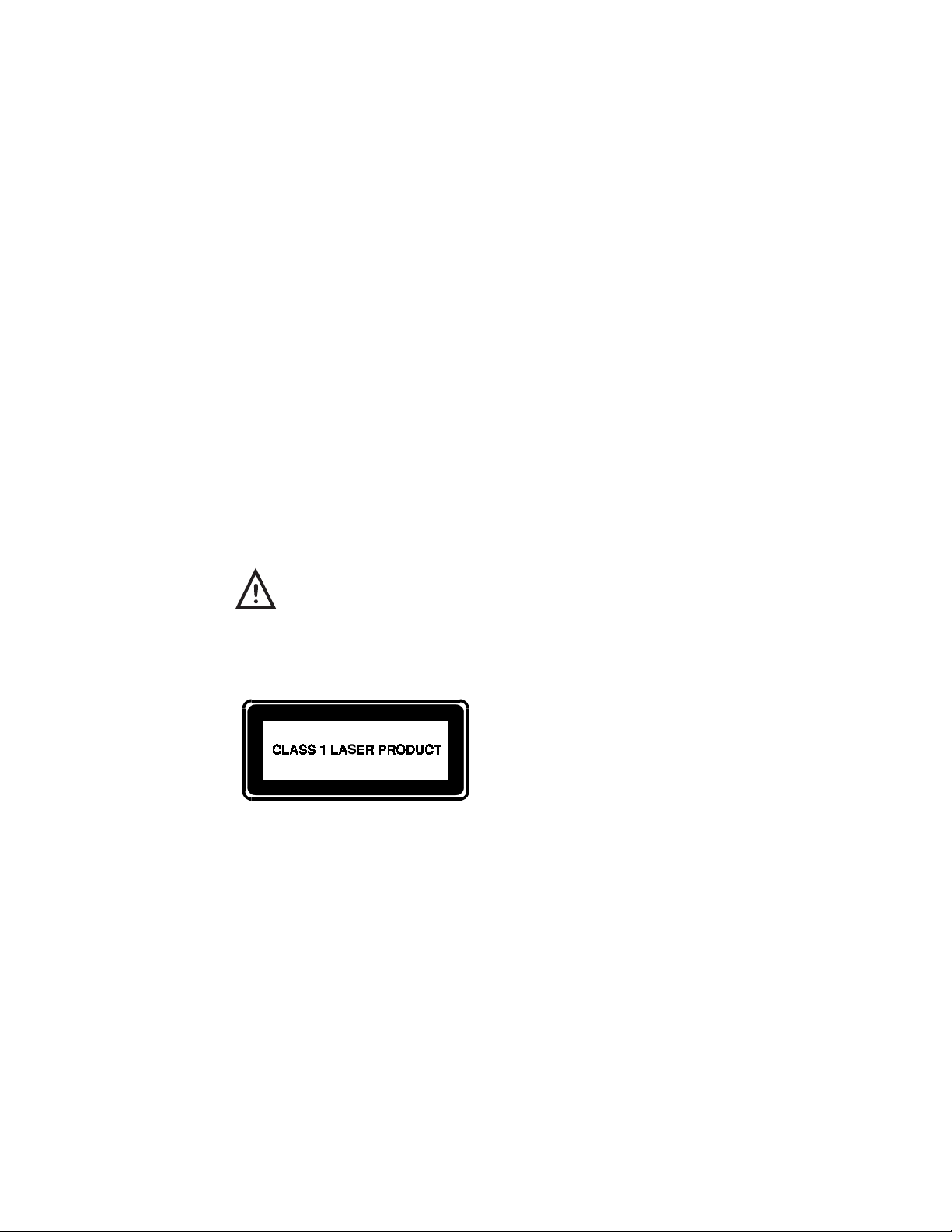
Regulatory Notices
greater than the voltage and current rating marked on the product. In addition, the diameter
of the wire must be a minimum of 0.75 mm²/18AWG, and the length of the cord must be
between 5 feet (1.5 m) and 6½ feet (2 m). If you have questions about the type of power
cord to use, contact your Compaq authorized service provider.
A power cord should be routed so that it is not likely to be walked on or pinched by items
placed upon it or against it. Particular attention should be paid to the plug, electrical outlet,
and the point where the cord exits from the product.
Laser Safety
All Compaq systems equipped with laser products comply with appropriate safety standards,
including IEC 825. With specific regard to the laser, the equipment complies with laser
product performance standards set by government agencies for Class 1 laser products. It
does not emit hazardous light; the beam is totally enclosed during all modes of customer
operation and maintenance.
CDRH Regulations
The Center for Devices and Radiological Health (CDRH) of the U.S. Food and Drug
Administration implemented regulations for laser products on August 2, 1976. These
regulations apply to laser products manufactured from August 1, 1976. Compliance is
mandatory for products marketed in the United States.
C-6
________________________WARNING___________________________
Use of controls or adjustments or performance of procedures
other than those specified herein or in the laser product
installation guide may result in hazardous radiation exposure.
____________________________________________________________
This system is classified as a Class 1 laser
product. This label appears on the laser
product.
Page 87

Laser Information
Laser Type: Semiconductor GaAlAs
Wave Length: 780 ± 35 nm
Divergence Angle: 53.5° ± 1.5°
Output Power: Less than 0.2mW or 10,869 W·m
Polarization: Circular
Numerical Aperture: 0.45 ± 0.04
Only authorized technicians trained by Compaq should attempt to repair this equipment. All
troubleshooting and repair procedures are detailed to allow only subassembly/module level
repair. Because of the complexity of the individual boards and subassemblies, no one should
attempt to make repairs at the component level or to make modifications to any printed
wiring board. Improper repairs can create a safety hazard.
Regulatory Notices
-2sr-1
C-7
Page 88

Regulatory Notices
Modem Notices
FCC Regulations - Part 68
To comply with the Federal Communications Commission (FCC) Rules and Regulations,
Part 68, these instructions must be followed:
1. Your modem must not be connected to a party line or coin-operated telephone.
2. If a problem occurs on the telephone line, your modem must be disconnected from the
telephone line until it has been determined that your modem is not the cause of the
problem.
3. All repairs to your modem must be made by Xircom, Inc. Unauthorized or unorthodox
repair methods can alter the modem’s radio frequency emissions and other
characteristics sufficiently to void your authority to operate the modem over a public
telephone network.
4. If requested, you must be prepared to provide the telephone company with the
following information:
Equipment Manufacturer: Xircom, Inc.
2300 Corporate Center Drive
Thousand Oaks, CA 91320-1420
U.S.A.
Model: CEM56-100
FCC Registration No.: 2U6USA-31569-M5-E
Ringer Equivalency No.: 0.7B
FCC Rules and Regulations - Part 68
This equipment complies with Part 68 of the FCC Rules. On the back of the CreditCard
Ethernet 10/100+Modem 56 is a label that contains, among other information, the FCC
Registration Number and Ringer Equivalency Number (REN) for this equipment. You must,
upon request, provide this information to your telephone company.
The REN is useful to determine the quantity of devices you may connect to your telephone
line and still have all those devices ring when your telephone number is called. In most but
not all areas, the sum of the RENs of all devices connected to one line should not exceed
five (5.0). To be certain of the number of devices you may connect to your line, as
determined by the REN, you should contact your local telephone company to determine the
maximum REN for your calling area.
C-8
Page 89

If your telephone equipment causes harm to the telephone network, the telephone company
may discontinue your service temporarily. If possible, they will notify you in advance. But if
advance notice is not practical, you will be notified as soon as possible. You will be
informed of your right to file a complaint with the FCC.
Your telephone company may make changes in its facilities, equipment, operations or
procedures that could affect the proper functioning of your equipment. If they do, you will
be notified in advance to give you an opportunity to maintain uninterrupted telephone
service.
If you experience trouble with this telephone equipment, please contact Xircom, Inc. at
(805) 376-9200 for information on obtaining service or repairs. The telephone company
may ask that you disconnect this equipment from the network until the problem has been
corrected or until you are sure that the equipment is not malfunctioning.
There are no user serviceable parts contained in this equipment.
This equipment may not be used on coin service provided by the telephone company.
Connection to party lines is subject to state tariffs.
Canadian Department Of Communications
Industry Canada (IC) Notice
This digital apparatus does not exceed the Class B limits for radio noise emissions from
digital apparatus set out in the Radio Interference Regulations of the Canadian Department
of Communications.
Regulatory Notices
Le présent appareil numérique n'émet pas de bruits radioélectriques dépassant les limites
applicables aux appareils numériques de Classe B prescrites dans le règlement sur le
brouillage radioélectrique édicté par le Ministère des Communications du Canada.
NOTICE:
means that the equipment meets telecommunications network protective, operational and
safety requirements as prescribed in the appropriate Terminal Equipment Technical
Requirements document(s). The department does not guarantee the equipment will operate
to the user’s satisfaction.
Before installing this equipment, users should ensure that it is permissible to be connected to
the facilities of the local telecommunications company. The equipment must also be
installed using an acceptable method of connection. The customer should be aware that
compliance with the above conditions may not prevent degradation of service in some
situations.
Repairs to certified equipment should be coordinated by a representative designated by the
supplier. Any repairs or alterations made by a user to this equipment, or equipment
malfunctions, may give the telephone communications company cause to request the user to
disconnect the equipment.
The Industry Canada (IC) label identifies certified equipment. This certification
C-9
Page 90

Regulatory Notices
Users should ensure for their own protection, that the electrical ground connections of the
power utility, telephone lines and internal metallic water pipe system, if present, are
connected together. This precaution may be particularly important in rural areas.
Caution: Users should not attempt to make such connections themselves, but should contact
the appropriate electric inspection authority, or electrician, as appropriate.
NOTICE:
provides an indication of the maximum number of terminals allowed to be connected to a
telephone interface. The termination on an interface may consist of any combination of
devices subject only to the requirement that the sum of the Ringer Equivalence Numbers of
all the devices does not exceed 5.
Warranty and Repair Service Center:
Safety Notices
This card is intended for use with UL 1950/EN60950/IEC950 (or other NRTL) listed ITE
computer that contains operator-accessible PCMCIA card slots.
The Ringer Equivalence Number (REN) assigned to each terminal device
REN: 0.4
IC Registration: 2117-8304A
Xircom, Inc.
2300 Corporate Center Drive
Thousand Oaks, CA 91320-1420
U.S.A.
Phone: (805) 376-9200
C-10
Page 91

British Approvals Board for Telecommunications (BABT)
The following information is provided in compliance with requirements of the British
Approvals Board for Telecommunications (BABT). It includes a sample “Application Form
for Installation of Modular Telephone Sockets.”
Xircom
CreditCard Ethernet 10/100+Modem 56
User’s Guide
p/n 800-0161-001/Revision B September 1997
This user guide refers to:
CreditCard Ethernet 10/100+Modem 56
Manufactured by:Xircom Europe n.v
King Square, De Villermontstraat 16
2550 Kontich, Belgium
Package Contents
The following items should be included in the package:
Regulatory Notices
Telephone cord and adapter (where appropriate)
Form to request installation of BT type socket (Application Form for Installation of
Modular Telephone Sockets).
If any of these items are missing or damaged please contact your supplier.
Statutory Notices
Please take careful note of the following regulatory information.
Network Connection
In order to connect to the UK national telephone network, the line cords provided with this
product are terminated with a BT-style modular plug type 431A. If you do not have BT
modular connection sockets, please contact BT Sales to arrange installation. The address and
telephone number can be found in your local telephone book.
All references to RJ11 connectors in the User’s Guide should be ignored.
The product features and modulation rates include V.34 at data rates up to 33.6 Kbps.
Power Requirements
All apparatus connected either directly or indirectly to a public telecommunications system
requires an approval. However certain attachments (including host computers) are eligible
C-11
Page 92

Regulatory Notices
for approval under General approval NS/G/1234/J/10003. Further details of this general
approval and the conditions pertaining to it are given in OFTEL update SA29, available
from:
The Librarian
OFTEL
Export House
50 Ludgate Hill
London
EC4M 7JJ
This modem is not approved for UK leased line operation.
Suitability for Use
If you have any doubt about the suitability, connection or use of this modem consult a
suitably qualified person before continuing.
The approval of this modem for connection to British Telecomm Public Switched
Telephone Network is invalidated if the modem is subject to any modification in any
material way not authorised by BABT or is used with or connected to :
1. Internal control software that has not been formally accepted by BABT.
2. External control software or external control apparatus which causes the modem or
associated call set-up equipment to contravene the requirements of BS6789:Section 3.2
C-12
All apparatus connected to this modem and thereby connected directly or indirectly to the
public switched telephone network must be approved apparatus as defined in Section 22(10)
of the British Telecommunications Act.
The modem is suitable for use on direct telephone lines operated by British
Telecommunications PLC, Mercury Communications PLC, and Kingston Communications
(Hull) PLC where the specific services of multi-frequency (tone) and/or loop disconnect
(pulse) dialing are available;
The modems are not suitable for use as an extension to a payphone, or on shared lines.
This apparatus may be connected to direct exchange lines or Relevant Branch Systems
(RBS) as defined in BS6789:Section 6.1 Clause 2.4 or compatible PABX systems.
(Including PABXs which return a secondary dial tone). Please contact Xircom for an up-todate list of compatible PABXs.
This modem may be used on two or three wire signalling systems.
This modem is not suitable for use as an extension to a payphone, or on shared lines.
This modem is intended for use in normal office, household and similar indoor use. It
should not be used in damp or humid environments such as bathrooms or swimming pools.
Page 93

The output power of this modem is fixed and cannot be changed by the user.
The approval mark attached to this product indicates that the modem itself carries BABT
approval. No approval is conferred on the host computer or the serially connected computer
and the label must not be transferred to the case of the computer. A copy of the approval
label may be attached to the telephone line cable. The approval label must not be removed.
The text of the approval mark is reproduced below:
APPROVED for connection to
telecommunications systems specified in the
instructions for use and subject to the conditions
set out in them.
The modem does not incorporate circuitry to suppress bell-tinkle during pulse dialing. When
used with some electronic ring type telephones and on two wire circuits that bell tinkle will
occur during pulse dialing. This is not a fault and we advise you not to call the Fault repair
service. This modem is not approved for use with parallel connected telephones when used
in public dialing mode.
Ringer Equivalence Number (REN)
REN is a customer guide to indicate the maximum number of apparatus that may be
connected simultaneously to a single telephone line without affecting the bell (or tone)
ringing characteristics of the items connected. The REN of each line connection of the
modem is 1. To calculate the maximum number of items that may be connected to a single
exclusive telephone line add all the REN values of the connected equipment. The total
should be 4 or less. Unmarked telephones are assumed to have a REN of 1. All other
equipment must be clearly marked with it REN value. If a REN of 4 is marked on the
apparatus, then only apparatus marked with a REN of 0 (zero) are permitted to be connected
simultaneously. Because of the wide spread of characteristics a guarantee of successful
operation in an installation of mixed types of equipment may not be given by the supplier.
Regulatory Notices
This apparatus has a REN of 1.0 for each line connection.
Hook Flash
The XircomUser’s Guide refers to “Hook Flash’ using the “!” dial modifier. For use in the
UK this modifier generates a momentary break of 95 ms (not 600 ms) in accordance with
UK type approval regulations. This timing is fixed.
Guard Tone
By default the &Gn command is set to n=2 (1800 Hz).
Speaker Control
The Mn command controls the signal presented to the host PC. There is no speaker on the
modem itself.
C-13
Page 94

Regulatory Notices
Pulse Dialing
The &Pn command is provided for software compatibility only. The pulse ratio is fixed at
67:33 and cannot be changed. The setting of this parameter is ignored by the internal control
software.
Timing
The S-Register ranges for S6, S7, S8, and S11 are restricted and cannot be altered outside
the UK permissible limits.
Repeat Attempts
The modem cannot initiate repeat call attempts. Ensure that host control software cannot
initiate repeat attempts which do not comply with BS6789:Section 3.1 Clause 7 call patterns
A,B,C or D. Table 3 call patterns is reproduced here to assist you in ensuring that your
software is correctly set.
Table 3 BS6789:Section 3.1 Repeat attempts, number of attempts, and duration between
attempts
C-14
Page 95

Regulatory Notices
Call Attempt Minimum duration between call attempts for call
Attempts ABCD
Initial attempt 5S 5S 5S 5S
1st repeat attempt 1 min 2 min 10 min 3 min
2nd repeat attempt 1 min 2 min 10 min 3 min
3rd repeat attempt 1 min 2 min 10 min 3 min
4th repeat attempt End of sequence
6th repeat attempt 2 min 10 min 3 min
7th repeat attempt (Note 1) 10 min 3 min
nth repeat attempt 10 min 3 min
pattern
(Note 1) 2 min 10 min 3 min
End of sequence
(note 2) (note 2)
Note 1: The maximum number of calls for repeat attempt call pattern A is 5 and for call
pattern B is 7.
Note 2: No limit is specified for n.
Note 3: The duration given in table 3 are from cleardown to reseizure.
Extracts from BS6789:Section 3.1:1985 are reproduced with permission of BSL. Complete
copies of the standard can be obtained by mail from BSI Sales.
Use as an Extension on an Approved PABX
Xircom cannot guarantee that this modem will operate correctly under all possible
conditions when connected to compatible PABX equipment. Any cases of difficulty should
be reported directly to Xircom.
This modem may not be connected to PABX systems which do not have a BT431A
compatible socket connection.
Bell Noise
This apparatus does not incorporate circuitry to suppress bell-tinkle during dialing. It has
been found that when used with some electronic ring type telephones and on two wire
circuits that bell tinkle will occur during dialing. This is not a fault and we advise you not to
call the Fault repair service.
C-15
Page 96

Regulatory Notices
Identification of Ports
The modems is fitted with a multi-way connector which provides the power and digital
signals to the modem. The RJ11 style connector provides the interface to PSTN.
Network Connection
The modem is supplied with a lead terminated with a BT modular plug. The connections are
as follows:
(PSTN) A Wire 2 B Wire 5
Dialing Modes
BS6789:Section 3.1 defines three dialing modes. Modes 2 and 3 cover autodialing devices
which play recorded messages. Mode 1 provided by this apparatus may be used for all nonemergency (non-999/non-112) calls. Mode 1 specifies that the device must drop the line
(hang-up) within 1 minute if it receives the standard BT tones for Number unobtainable,
Busy, Equipment engaged or special information. Calls not covered by modes 1,2 or 3 must
not be made.
The modem in this unit, since it uses mode 1, cannot be, must not be, used for emergency
(999/112) calls.
Available Facilities
This apparatus has been approved for the use of the following facilities:
· Data transmission speeds up to 33.6kbps and reception speeds up to 56kbps
· Operation to CCITT V21, 22, 22bis, 23, 27, 29, 32, 32bis, 34 signalling rates
· Automatic call initiation
· Detection of initial proceed indication (dialtone) and secondary dialtone
· Operation in the absence of initial proceed indication (blind dialing)
· Automatic dialing using dtmf (tone) or loop disconnect signalling (pulse dialling).
· Tone detection of Dialtone, Ring tone, Busy, Equipment busy, Number
unobtainable
· Automatic answering
· Stored and Last Number dialing
· Timed break register recall
Any other usage will invalidate the approval status if as a result, the apparatus then ceases to
conform to the standards against which they were tested and approved.
Additional Features
Since this modem is capable of storing telephone numbers for autodialing, you are required
by BS 6789:Section 3.1 to ensure that all stores have been correctly entered. Commands are
provided for this purpose.
C-16
Page 97

Regulatory Notices
Application Form For Installation Of Modular Telephone Sockets
To the customer:
If your current telephone installation is not equipped with the new modular telephone socket
you must have one fitted by your telephone service provider. Please complete this form and
return it to your local telephone sales office. You will find the address and telephone
number in the your telephone directory.
Name:_____________________________________________________
Address: ___________________________________________________
___________________________________________________________
___________________________________________________________
Postcode: ________ Telephone Number:______________
To Telephone Sales:
Please quote for the supply and fitting of a modular telephone socket at the above address.
The equipment to be connected is:
___________________________________
Approval Number: ____________________
The REN of the equipment is: ___________
International Notice
Due to differing national regulations and approval requirements, certain Xircom products
are designed for use only in specific countries, and may not function properly in a country
other than the country of designated use. As a user of these products, you are responsible for
ensuring that the products are used only in the countries for which they were intended.
For information on specific products, contact Xircom’s nearest regional center:
Xircom Corporate (U.S.A.)
Xircom Europe
Xircom Asia Pacific
(800) 438-4526
+32/(0)3 450.08.11
+65 323 1511
C-17
Page 98

Regulatory Notices
Modem Approvals
Your modem is approved in the following countries:
________________ Telecom Network Approvals ___________________
The telecommunications device in your computer is approved for connection to
the telephone network in the countries whose approval markings are indicated on
the product label. Additional country approvals may be found on the Compaq
web site. To view these approvals, visit http://www.compaq.com and perform a
site search for the words "telecom network approvals." If a selection is available
for your product, you may view and print the approval marks or numbers.
____________________________________________________________
Area Country Approval Number
Europe
Austria 105473ZB9740
Belgium BE97MA0587
Czech Rep T973
Denmark DK97022533
C-18
Finland F197615065
France 98004F
Germany D132976J
Ireland DOC112/97
Italy 1998MDSM042
Luxembourg L 1113/10348-01H
Netherlands NL97211383
Norway N097000733-D
Poland 191/98
Portugal ICP.98.017
Slovakia test date to be set
Spain 08 98 0234
Page 99

Area Country Approval Number
Europe
Sweden 97122210
Switzerland BAKOM97.1183.D.N
United Kingdom 607463
Regulatory Notices
Asia/
Pacific
Australia
China US approval sufficient or no approval needed
Hong Kong See BABT
India No Approval Needed
Indonesia No Approval Needed
Japan S98-2319-2
South Korea 1GD-MYS-A22-978-1232
Malaysia DAFG/65B/0797M
New Zealand PTC 211/98/050
Phillipines No Approval Needed
Singapore PSTN1-FAXM-AF-0713-97
Thailand No Approval Needed
C-19
Page 100

Regulatory Notices
C-20
 Loading...