

Page 1

Notice
The information in this guide is subject to change without notice.
COMPAQ COMPUTER CORPORATION SHALL NOT BE LIABLE
FOR TECHNICAL OR EDITORIAL ERRORS OR OMISSIONS
CONTAINED HEREIN; NOR FOR INCIDENTAL OR
CONSEQUENTIAL DAMAGES RESULTING FROM THE
FURNISHING, PERFORMANCE, OR USE OF THIS MATERIAL.
This guide contains information protected by copyright. No part of this
guide may be photocopied or reproduced in any form without prior
written consent from Compaq Computer Corporation.
©1998 Compaq Computer Corporation. All rights reserved. Printed in
Singapore.
Compaq and LTE are registered in the U.S. Patent and Trademark
Office. Armada is a trademark of Compaq Computer Corporation.
Microsoft, MS-DOS, and Windows are registered trademarks of
Microsoft Corporation.
The software described in this guide is furnished under a license
agreement or nondisclosure agreement. The software may be used or
copied only in accordance with the terms of the agreement.
Product names mentioned herein may be trademarks and/or registered
trademarks of their respective companies.
REFERENCE GUIDE
Compaq Armada 4200 Family of Personal Computers
First Edition (January 1998)
Part Number 290779-001
Compaq Computer Corporation
Page 2

CONTENTS
preface
BEFORE YOU BEGIN
chapter 1
FINDING INFORMATION ABOUT YOUR COMPUTER
Printed and On lin e R eferen ces ...................................................1-1
Online Optio n s C atalo g ..............................................................1-2
Ordering Backup Software.........................................................1-2
chapter 2
TAKING A LOOK AT THE COMPUTER
Front and Left Side Components................................................2-2
Front and Right Side Components..............................................2-3
Keyboard Components...............................................................2-4
Status Pan el Lights .....................................................................2-6
Rear Components........................................................................2-7
Bottom Components...................................................................2-9
Versatile Handle .......................................................................2-1 0
External Diskette Driv e B ay.....................................................2-10
chapter 3
USING KE YBO ARD SHORTCUTS
User-Programmab le Keys...........................................................3-2
Assign in g P ro g rammab le Key s ..............................................3-2
Unassign i n g User-P ro g rammab le Key s..................................3-3
Adding S ch emes.....................................................................3-4
Removin g S ch e mes ................................................................3-4
Key Assign men ts o n th e Task b ar ...........................................3-4
Using the Ho tk ey s ......................................................................3-5
Using Sp ecial Fu n ctio n Key s ......................................................3 -7
Using the Nu meric Key p ad.........................................................3-8
Contents v
Page 3

chapter 4
WORKING WIT H POINTING DEVICES
Mouse Utility ..............................................................................4-2
Touchpad Components ...............................................................4-3
Trackball Components................................................................4-4
Removin g a Po in tin g Dev i ce ...................................................... 4 -5
Installing a Po in tin g Dev ice........................................................4-7
chapter 5
MANAGING POWER
Power Butto n ..............................................................................5 -2
Power Cho i ces ........................................................................5-3
Suspen d B u tto n...........................................................................5 -3
How Suspen d Is In itiated........................................................5-4
Initiating Su sp en d................................................................... 5 -4
Exiting Su s p en d......................................................................5 -5
Hibernation .................................................................................5-6
Initiating Hib ern atio n .............................................................5-6
Exiting Hib ern atio n ................................................................ 5 -7
AC Power....................................................................................5 -7
Battery Power..............................................................................5 -9
Battery Ch arg in g / Dis ch arg in g ................................................5 -9
Comparin g B attery Ty p es..................................................... 5 -1 0
Resolvin g a Lo w-B attery C o n d itio n.....................................5-11
Extendin g B attery Pack Op eratin g Time ..............................5-12
Chargin g th e Ba ttery Pack (s )................................................5-13
Recycling Us ed Batteries in No rth America.........................5-14
Recycling Us ed B atteries in Eu ro p e .....................................5 -1 4
Power Properties Utility............................................................5 -1 5
Battery Statu s Tab.................................................................5-16
Setting Battery C o n s erv atio n Lev els ....................................5-1 7
Setting a Timeo u t..................................................................5 -1 8
Turning Hib ern atio n On o r Off.............................................5-1 9
The Battery Gauge Popup.....................................................5-20
chapter 6
USING THE HANDLE
Handle Fu n ctio n s ........................................................................6 -1
Attaching th e Han d le ..................................................................6-2
Detaching th e Han d le..................................................................6-3
vi Contents
Page 4

Handle Tilt Feature.................................................................6-5
Removin g /In s ertin g th e Han d le B attery .....................................6-5
chapter 7
USING THE DUALBAY
Inserting/ R emo v in g th e Dis k ette Driv e ......................................7-2
Inserting a Dis k ette.....................................................................7-4
Removin g a Dis k ette...................................................................7 -4
Removing/Inserting the Modular Battery...................................7-5
chapter 8
USING THE EXTERNAL DISKETTE DRIVE BAY
Inserting the Diskette Drive into th e
External Diskette Driv e B ay.......................................................8-2
Removing the Diskette Drive from the
External Diskette Driv e B ay.......................................................8-3
chapter 9
ENJOYING COMPAQ AUDIO
Identifying Built-In Audio Components.....................................9-2
External Aud io J ack s..............................................................9 -3
Stereo Line-In J ack.................................................................9-4
Internal Microphone...............................................................9-5
Volume Co n tro l ..........................................................................9-6
Using the S tereo Sp eak ers ..........................................................9-7
chapter 10
CONNECT ING EXTERNAL DEVICES
Configu ratio n Utilities..............................................................10-2
Device Manager Utility ........................................................10 -2
Add New Hardware Utility...................................................10-2
Using PC C ard s ........................................................................10 -3
Understan d in g Plug and Play ...............................................1 0 -4
Managin g PC C ard P o wer ....................................................10-4
Inserting a PC C ard ..............................................................10 -5
Removin g a P C C ard ............................................................10-6
PC Card S o ftware .................................................................1 0 -7
USB CardB u s PC C ard.........................................................1 0 -7
Conn ectin g Vid eo.....................................................................10-7
Using the Vid eo Utility ........................................................10-7
Contents vii
Page 5

Connectin g a TV o r VC R .....................................................10-8
Displayin g P ictu res...............................................................10-9
Conn ectin g In frared Eq u i p men t..........................................10 -1 0
chapter 11
ADDING SOFTWARE AND UPGRADES
Installing S o ftware....................................................................11 -2
Operating System Support........................................................11-2
Upgradin g Memo ry................................................................... 1 1 -3
Memory Upg rad e Op tio n s .................................................... 1 1 -3
Checkin g C u rren t Memo ry ...................................................11 -3
Adding Memo ry....................................................................1 1 -4
Upgrading th e Hard Driv e.........................................................1 1 -5
chapter 12
SETTING SECURITY FEATURES
Setting Pas s wo rd s Pro perties.................................................... 1 2 -2
Power-On Pas s wo rd..................................................................1 2 -2
Establishin g a P o wer-On Pas s wo rd ..................................... 1 2 -2
Entering th e Po wer-On Pa ss wo rd ......................................... 1 2 -3
Deleting/Ch an g in g Po wer-On P as sw o rd ..............................12-3
If You Forg et Your Power-On P as sw o rd..............................12-3
Establishin g a S etu p Pas s wo rd ..................................................1 2 -4
Deleting/Ch an g in g a Se tu p Pas s wo rd...................................12-5
Identifyin g Qu ick C o n tro ls .......................................................12 -5
Initiating Qu ick Co n t ro ls......................................................12-6
Using a Ca b le Lo ck...................................................................1 2 -7
chapter 13
CARING FO R T HE COMPUTER
Routin e C are .............................................................................1 3-2
Travel Guidelin es......................................................................1 3 -3
Shippin g Gu id elin es..................................................................13-4
chapter 14
COMPUTER SETUP AND DIAGNOSTICS
Setup and Diagnostics Utilities.................................................1 4-2
Accessing C o mp u ter S etu p .......................................................1 4 -2
Accessing Diagnostics Utilities................................................14-3
Diagnostics for Windows......................................................14-3
viii Contents
Page 6

Compaq Diagnostics.............................................................14-4
Running Computer Checkup (TEST).......................................14-4
Running the View System Information
(Inspect Utility ) ........................................................................14-6
chapter 15
TROUBLE SHO OTING
Checklist...................................................................................15-1
Interpreting Mess ag es o n th e Sc reen .......................................15-2
Solving Minor Prob lems...........................................................15-3
Solving B a ttery Pro b l ems.....................................................15-3
Solving Disk ette/Dis k ette Driv e Pro b lems...........................15 -6
Solving Hard Driv e Pro b l ems...............................................15 -7
Solving Hard ware In s tallatio n Pro b l ems..............................15-8
Solving Keyboard and Embedded
Numeric Keypad P ro b lems...................................................1 5 -9
Solving Memory Prob lems .................................................15 -1 0
Running the Monitor Self-Test ...........................................15-10
Solving P C C ard Pro blems.................................................1 5 -1 1
Solving P o wer P ro b lems ....................................................15 -1 3
Solving P rin ter Pro blems....................................................15 -1 4
Solving Dis p lay Screen P ro b lems ......................................15-15
Solving So ftware Ap p licatio n P ro b lems ............................15-1 7
Solving Sound Problems....................................................15-17
Solving Po in tin g Dev i ce Pro b lems.....................................15-18
Cleaning th e Track b all .......................................................15-2 0
Cleaning In si d e th e Track b all As se mb ly............................15 -2 1
Servicing th e C o mp u ter......................................................1 5 -2 2
Preparing for a Call to Customer Support..........................15-23
chapter 16
INTELLIGENT MANAGEABILIT Y
Access to Intellig en t Man ag eab ility .........................................1 6 -1
Features and B en efits................................................................16 -1
Asset Manag emen t....................................................................16 -2
Fault Manag emen t ....................................................................16 -2
Security Mana g emen t ...............................................................16-3
Contents ix
Page 7

appendix A
WORLDWIDE TELPHONE NUMBERS.....................................................A-1
appendix B
POST ERROR MESSAGES.................................................................B-1
appendix C
CONNECT O R PIN ASSIGNMENTS ........................................................ C-1
appendix D
POWER CORD SET REQ UIREME NT S
General Requ i remen ts................................................................D-1
Country-Specific Requirements.................................................D-2
appendix E
ELECT RO ST AT IC DISCHARGE
Preventing Electro s tatic Dis ch arg e ............................................ E-1
Grounding Methods................................................................... E-1
appendix F
AGENCY REGULAT O RY NOTICES
Agency Re g u lato ry Id en tificatio n Nu mb ers ...............................F-1
Battery Notice.............................................................................F-4
Energy St ar C o mp lian ce .............................................................F-5
appendix G
SPECIFICATIONS ..............................................................................G-1
rd appa.doc
INDEX................................................................................................ I-1
x Contents
Page 8

preface
BEFORE YOU BEGIN
Some or all of the following f ormat c onventions are used in this
guide to distinguish elements of text :
■
Names of keys are shown in bold type as they appear on the
keyboard, for example,
■
Keys that you should press at the same time are represente d by
the key names and the plus (+) symbol, for exam ple,
Ctrl+Alt+Delete.
Ctrl, Backspace, Tab.
■
Commands are presented in lowercase, bold type as shown
here:
■
An arrow symbol is used to se parate ic ons or menu options
install or a:\inst all.
that you should select in succession, for example, click the
Start buttonÈSettingsÈControl Panel.
■
When you need to type i nformation without pre ssi ng the Enter
key, you are direct ed to “type” the information.
■
When you need to type information and press the Enter key,
you are directed to “enter” the information.
NOTE: Text set off in this manner present s c ommenta ry, sidelight s,
or intere sting points of inf ormation.
IMPORTANT: Text set off in this manner presents clarifying
information or specific instructions.
WARNING: Text set off in this manner indicates that failure to
!
follow directions could result in bodily harm or loss of life.
CAUTION: Text set off in this manner indicates that failure to follow
directions could result in damage to equipment or loss of
information.
Before You Begin xi
Page 9

chapter
1
FINDING INFORMATION ABOUT
YOUR COMPUTER
In this chapter you will learn a bout the referenc e s that come with
your computer and where to find them.
Refere nc es are pr ovi ded for you in two forms:
■
As printed materials
■
As online information accessible from the computer screen
NOTE: The references that come with the computer vary by model.
Printed and Onl ine References
The foll owing printe d refer ences come with your computer :
■
A quick setup poste r
■
Reference Guide
■
Microsof t Windows Operating System Guide
■
Safety & Comfort Guide
■
Kensington Sec urity Card
■
Warranty and service information
The foll owing Compaq onli ne refe rences a re preinstalled on your
computer:
■
Compaq Reference Guide
■
Safety & Comfort Guide
■
Compaq Dictionary
■
Options Catalog
Finding Informati on A bout Your Computer 1-1
Page 10

The online references installed on the computer include the user’s
guides, application help, software utilities help, and customer
support information. Ma ny are accessible from the Compaq
Information Center folder on the Sta rt menu. Others can be
accessed from the application or utility screens.
CAUTION: Most online references are available only through the
Windows interface. If you delete Windows, those references will also
be deleted. Therefore, Compaq recommends that you not delete
Windows software.
Online Options Catalog
To learn more about t he many Compa q opt i ons designed to
enhance your computer, go to the Compaq Information Ce nter on
the Start menu. Click the Options Catalog to see an illustration
and descri pt ion of the m any options for your compute r. Use t he
part number include d to order from your Compaq dealer, re seller,
or service provider.
Ordering Backup Sof tware
Compaq rec ommends that you create a backup of the softwar e
preinstalled on the computer. Or, for an additional cost , you can
order a ba ckup CD or diskett es from Compaq for al l softwar e
preinstalled on this computer.
To order ba ckup diskettes or CDs, refer to the “ Worldwide
Telephone Numbers” listed in Appendix A. If an orde r form is
included wi th your comput er, complete the form and return it. Or
call one of the numbers liste d on the order form.
IMPORTANT: Before calling Compaq to place your order, find the
serial number on the bottom of your computer. This number is
necessary for all backup diskette or CD purchases.
1-2 Finding Informat ion About Your Computer
Page 11

chapter
2
TAKING A LOOK AT THE
COMPUTER
Your com put er is equipped with many features, including
hotkeys, progr ammabl e keys, light indicators, a nd c onnectors.
This chapter familiarizes you w ith the components on the
computer and how to use them.
Externa l devices such as a print er, port able expansi on uni t,
monitor, keyboard, or mouse can be connected to your com puter
to enhance its functionality. See Chapter 10, “Connecting External
Devices,” for more details.
Illustra tions and tables on t he following pages identify the
computer’s primary components, inc luding:
■
Front and left side c omponents
■
Front and r ight side components
■
Keyboard c omponents
■
Status panel lights
■
Rear components
■
Bottom components
■
Versatile handle
■
External Diskette Drive Bay
Taking a Look at the Computer 2-1
Page 12
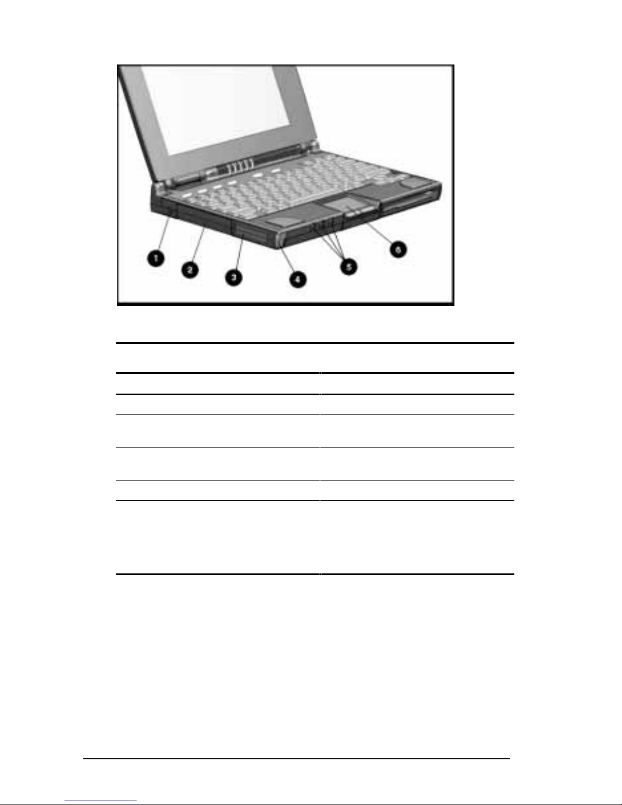
Front and Left Side Components
Front and Left Side Com ponent s
Front and Left Side of the Computer
Ref. Component Function
1 Cable lock provision Protects your computer from theft.
2 Hard drive Drive inside your computer that
stores data.
3 PC Card slots Accept one Type III, or two Type
II, or two Type I PC Cards.
4 PC Card eject buttons Release PC Cards.
5 Audio connectors Allow you to connect a
microphone, stereo, or headphone
to your computer. (See Chapter 9,
“Enjoying Compaq Audio,” for
details.)
2-2 Taking a Look at the Computer
Page 13

Front and Right Side Components
Front and Right Side Components
Front and Right Side of the Computer
Ref. Component Function
1 DualBay Accepts an internal diskette drive
(3.5-inch diskettes) or modular
battery pack.
2 DualBay eject button Ejects the diskette drive or
modular battery pack.
3 AC power connector Connects the AC Adapter to the
computer. Use the power cord
extension included with your
computer when you need to reach
a distant electrical outlet to
connect the AC Adapter.
Taking a Look at the Computer 2-3
Page 14

Keyboard Components
Keyboard
Keyboard Components
Ref.Component Function
1 Function keys
Fn+F1 - Fn+F10
2 User-programmable
keys
3 Suspend button When pressed once with the computer on,
4 Status panel lights Display computer status indicators.
5 Power button When pressed the first time, turns on the
Used for specific functions in applications
and operating systems.
Assign and launch applications or
documents quickly and emulate Windows
and Application Logo Keys.
initiates Suspend; when pressed the second
time, exits Suspend; when pressed
simultaneously with Fn, initiates Hibernation.
computer. (See chapter 5, “Managing
Power,” for details.)
NOTE: To turn off the computer, use Shut
Down from the Windows Start menu. In case
of a system lockup, when the mouse doesn’t
work and Ctrl+Alt+Del is not recognized by
the unit, press Power or Ctrl+Power to turn off
the unit.
6 Embedded numeric
keypad
2-4 Taking a Look at the Computer
Allows two operating modes, numeric (if
Fn+NumLk is on) and edit (if Fn+NumLk is off).
Page 15

Continued
Taking a Look at the Computer 2-5
Page 16

Keyboard Components Continued
Ref.Component Function
7 Arrow keys Allow cursor to move up, down, right, left.
8 Stereo speakers Produce high-quality stereo sound.
9 Pointing device The touchpad moves the pointer around the
screen and functions as a portable mouse.
2-6 Taking a Look at the Computer
Page 17

Status Panel Li ghts
Status Panel Light s
Status Panel Lights
Ref. Indicator Function
1 Power/
Suspend
2 Battery
charge
3 Caps Lock Turns on when Caps Lock function is on.
4 Scroll Lock Turns on when the Scroll Lock function is on.
5 Num Lock Turns on when the NumLk function is on.
Turns on (solid) when power to the computer is
turned on; blinks in Suspend mode; turns off when
computer is in Hibernation or powered off.
Turns on (solid) when computer is turned on and
when battery is fast charging. If a low-battery point
is reached, light will flash 6 times and you’ll hear a
beep. If a critical low-battery state is reached,
you’ll hear a beep and the light will flash
constantly. If you do not attach an AC Adapter
within 20 seconds of this warning, the unit will
initiate Hibernation (unless Hibernation has been
disabled).
Taking a Look at the Computer 2-7
Page 18

Rear Components
Rear Components
Rear of the Computer
Ref Component Function
1 Keyboard/mouse connector Connects an external keyboard,
mouse, or other compatible PS/2
pointing device.
2 Parallel connector Connects optional parallel devices,
such as a printer. Also connects the
External Diskette Drive Bay.
3 Serial connector Connects optional serial devices,
such as a mouse.
4 Infrared lens (IrDA
compliant)
5 External monitor connector Connects external monitor to computer
Sets up wireless data transfer for
printing.
Continued
2-8 Taking a Look at the Computer
Page 19

Rear Components Continued
Ref Component Function
6 NTSC/PAL Video Connects the computer to TV, VCR,
camcorder, or laser disc, using the
NTSC (U.S.) and PAL (European)
formats. You can use the NTSC/PAL
cable included with your computer to
make video connections.
IMPORTANT: See “Connecting Video”
in Chapter 10, “Connecting External
Devices,” for information regarding
the U.S./European video connectors.
7 Status panel indicator
lights
Status panel lights remain in view
when the computer is closed.
Taking a Look at the Computer 2-9
Page 20

Bottom Components
Bottom Components
Bottom of the Computer
Ref Component Function
1 DualBay Accepts an internal diskette drive
(3.5-inch diskettes) or modular
battery pack.
2 Pointing device The touchpad moves the pointer
around the screen; functions as a
mouse.
3 Memory compartment Stores the memory expansion
boards.
4 Expansion slot 120-pin connector interface for
the Mobile CD Expansion Unit
(MCD) or convenience base.
5 Hard drive compartment Contains the hard drive.
2-10 Taking a Look at the Computer
Page 21

Versatile Handle
A multifunctional handle with a Lithium Ion battery pack inside
provides more porta bl e power by adding a second battery pack. In
addition, the handle moves to three convenient positions:
■
Creates a comfortable tilt f or working at the keyboar d. Fold
the handle ba ck and under the computer.
■
Provides a cover for the rear connectors. Place the handle in a
straight posit ion while the computer i s lying flat.
■
Enables you to carry the c omputer like a brief case.
NOTE: For more information about the handle, see Chapter 6,
“Using the Handle.”
Versatile Handle
External Di skette Drive Bay
When you want to ope rate on battery powe r but need to use the
diskette drive, install the drive in the external drive bay. It
includes a parallel cable that connects to the parallel port on the
rear of the computer.
See Chapter 8, “Using the External Diskette Drive Bay,” for
details on how to use this f eature.
Taking a Look at the Computer 2-11
Page 22

chapter
3
USING KEYBOARD SHORTCUTS
Keyboard shor t cuts help you customize the keyboard. You ca n
use designated keys to change and se l ect computer settings, such
as speaker volume, battery c onservation, and popup windows.
This chapter familiarizes you w ith the following keyboard and
shortcut f eatures :
■
User- programmable keys
■
Hotkeys
■
Special function keys
■
Embedded numeric keypad
Using Keyboard Shortcuts 3-1
Page 23

User-Programmable Keys
The four use r-programmable keys è at the top of the keyboar d
allow you to quickly open an appl i cation on your c omputer, bring
up a document , or em ul ate one of t he Microsoft Windows and
Applicati on Logo Keys.
User Programmable Keys
By assigning the programmed keys to schem es, you can cr eate
multiple sets of key assignments that will allow you to open
almost a ny applicati on or document on your compute r.
Assigning Progr ammable Keys
To assign user- programmable keys, f ol l ow t hese steps:
1. Access the Programmable Keys utility in the Control Panel on
the Windows Sta rt button.
2. Select the program mable key you w ant to assign or r eassign in
the current scheme by clicking the appropriate r adio button in
the Key assignments group box.
NOTE: To assign keys in other than the current scheme, place a
check in the Show advance d options checkbox and look in the
Scheme box t o see the scheme you are c urrently using. You can
create a new scheme or add/change key assignments in the current
scheme. If you have never created a scheme, the Default sche me
will be in effect.
3-2 Using Keyboard Shortcuts
Page 24

3. Click the Assign but ton. A dialog box a ppears showing a l ist
of programs or documents from the Programs menu.
NOTE: To access a larger number of programs, click the Show
advanced options checkbox. This changes the Assign but ton
to the Browse button. By clic ki ng the Browse butt on, you can
access all applications on your computer. To em ulate one of
the Micr osoft Windows and Application Logo Keys, select the
appropriate file from the WINDOWS\CPQWIN directory.
4. Highlight the desired appl ication and click OK. The icon and
program na me you selected will appear beside the
programmable key’s radio button.
5. Click OK to exit this utility. When you push the
program mable key you just assigned, your a pplication or
document will appear on screen.
Unassigning User-P rogrammable Keys
To remove a programmable key assignment, follow these steps:
1. Access the Programmable Keys utility in the Control Panel.
2. Select the programmable key you wish to unassign by clicking
the appropriate r adio button in the Key assignments group
box.
NOTE: To assign keys in other than the current scheme, place a
check in the Show advance d options checkbox and look in the
Scheme box t o see the scheme you are c urrently using. You can
create a new scheme or add/change key assignments in the current
scheme. If you have never created a scheme, the Default sche me
will be in effect.
3. Click the Assign button, then select Unassigned from the list.
The icon and program name previousl y assigned to the key
will be removed.
NOTE: When the Show adva nced options box is checked, you can
unassign a programmabl e key by clicking t he Browse button a nd
selecting “U nassigned” in the WINDOWS\CPQWIN directory.
4. Click OK to exit the utility.
Using Keyboard Shortcuts 3-3
Page 25

Adding Schemes
A scheme i s a program mable key a ssignment that you define and
is unique to your Windows user prof ile.
To add a new sc heme, do the following:
1. Access the Programmable Keys utility in the Control Panel.
2. Click the Show advanced options checkbox.
3. Click the Add button.
4. Type the name of your new sc heme in the popup dialog box
that appears.
5. Make your progra mmable key assignments .
6. When the assignments have been made, click OK to exit the
utility.
Removing Schemes
To remove a new scheme, do the following:
1. Access the Programmable Keys utility in the Control Panel.
2. Place a check in the Show advanced options checkbox if one
is not already there.
3. Be sure the scheme in the S cheme box is t he one you want to
delete. To view a different scheme, select a sc heme fr om the
drop-down li st.
NOTE: The Default sc heme is not removable .
4. Click the Remove button.
5. Click OK to exit the utility.
Key Assignments on the Taskbar
One convenient way to see your user-programmable key
assignments i s t o vi ew them in a popup window that you activate
from an icon in the system tray (taskbar). To enable the icon:
1. Access the Programmable Keys utility in the Control Panel.
2. Place a check in the Show key assignments in the System Tray
checkbox.
3. Click OK to exit the utility.
An icon appears in the taskba r. To view the popup window, c lick
the icon.
NOTE: The icon remains in the system tray (taskbar) until you
disable it by unc hecking Show Key Assignments in the System
Tray checkbox.
3-4 Using Keyboard Shortcuts
Page 26

Using the Hotkeys
The hotkey combinations (Fn+F1 - F10) allow you to use the arrow
keys to quickly adjust computer settings using the Fn plus hotkeys
F1 through F10. To use the arrow keys to adj ust se ttings, hold
down the hotkeys w hile using the up, down, right, or left arr ow
keys.
Hotkeys
NOTE: When you press most hotke ys t he second time, the keys are
toggled off . An exception is the
Fn+F6 QuickLock/QuickBlank
hotkeys, which require t he power-on password to disable .
Hotkey Assignments and Functions
Feature Hotkeys Function
Popup icon
location
BIOS version Fn+F2 Displays the BIOS version number.
Switches displays Fn+F4 Toggles between computer display,
Speaker volume Fn+F5 Adjusts speaker volume up or down.
Fn+F1 Adjusts the popup icon location. Use
the arrow keys to move the icon up or
down, left or right.
external monitor display, both displays
at the same time, or TV screen.
Continued
Using Keyboard Shortcuts 3-5
Page 27

Hotkey Functions and Assignments Continued
Feature Hotkeys Function
Quick Lock/
QuickBank
Battery
Conservation
Fn+F6 Initiates QuickLock, which disables the
keyboard and mouse, and QuickBlank,
which clears the screen. Enter poweron password to disable QuickLock and
QuickBlank and reactivate keyboard,
mouse, and screen.
Fn+F7 Displays the battery conservation
settings in a popup window. Use the
left and right arrow keys to select a
different setting.
NOTE: See Chapter 5, “Managing
Power,” for more information.
Battery Gauge Fn+F8 Press the right or down arrow keys to
select the next battery to be displayed.
If a battery is not present, its selection
will be skipped. Pressing left or up
arrow keys will select the previous
battery. If the user does not depress
any arrow keys for 5-7 seconds, the
popup will display the average
remaining capacity of all installed
batteries.
NOTE: See Chapter 5, “Managing
Power,” for more information.
Contrast Control Fn+F9 Adjusts the display contrast. Press the
right arrow key to increase contrast;
press the left arrow key to decrease
contrast.
NOTE: On models with active matrix
display, contrast control is not
applicable.
Brightness Control Fn+F10 Adjusts the display brightness. Press
the right arrow key to increase light
intensity; press the left arrow key to
decrease light intensity.
Hibernation Fn+
suspend
Num Lock Fn+Num Lk Enables and disables the embedded
Initiates Hibernation.
numeric keypad.
3-6 Using Keyboard Shortcuts
Page 28

Using Special Funct ion Keys
Some keys on t he keyboard pr ovide special functions, depending
on the applica t i on you are using. These keys ar e described i n t he
following table:
Special Function Keys
Key Function
Alt Application dependent, used in combination with
another key for a specific function. Refer to the
documentation for the application you are using.
Backspace Moves the cursor left and deletes characters as it
moves left.
Caps Lock When the CapsLock indicator is on, all letters typed are
capitalized.
Ctrl Application dependent; used in combination with other
keys for specific functions. Refer to the documentation
for the application software you are using.
Esc Often assigned a specific task by the application.
Frequently used as an exit key.
F1 – F 12 Used for a specific function in applications and
operating systems. Check the documentation for the
application software you are using.
NumLk Activate this function by pressing Fn+NumLk. When the
NumLk indicator light is on, the embedded numeric
keypad is activated. Use this toggle key feature to
enable and disable the numeric keypad.
Pause Temporarily suspends screen scrolling. Activate this
function by pressing Fn+Pause. Deactivate Pause by
pressing any key.
PrtSc Prints the information on the screen line-by-line to a
local printer. Using this key will print only the
information on the screen. Activate this function by
pressing Fn+PrtSc.
Scroll When the Scroll Lock indicator light is on, prevents the
screen from scrolling. Access this function by pressing
Fn+Scroll.
Continued
Using Keyboard Shortcuts 3-7
Page 29

Special Function Keys Continued
Key Function
Ctrl+Alt+Delete Restarts the system after the computer has been
turned on and is locked up while in MS-DOS mode.
NOTE: Shut Down on the Windows Start menu is
the recommended way to restart the computer while
in Windows. Also stops the restoration of information
when the computer exits Hibernation.
Fn + suspend Initiates Hibernation.
Ctrl+Power Resets the system in case of a system lockup, when
the mouse doesn’t work and Ctrl+Alt+Del is not
recognized by the unit.
Using the Numeri c Keypad
The embedded numeric keypad is a section of the keyboard t hat
converts to a numeri c keypad when t he NumLk function is
activate d. This is done by pressing Fn+NumLk. Us e this toggle key
function to enable and disable the embedded numeric keypad.
Embedded Numeric Keypad
3-8 Using Keyboard Shortcuts
Page 30

chapter
4
WORKING WITH
POINTING DEVICES
The pointing device on your c omputer is a versatile feat ure that
eliminates the need to carry a mouse when traveling. It moves the
cursor around the screen and can be used w ith either hand.
This com puter can use either a modular touchpad or trackball
pointing device. Your c omputer comes wit h a touchpad.
This chapter familiarizes you w ith trackball and touchpad
features, incl uding:
■
Accessing the mouse utility
■
Identif ying touchpad components
■
Identif ying trackba ll components
■
Removing the pointing device
■
Installi ng a pointing device
Working with Pointing Devices 4-1
Page 31

Mouse Utility
Button functi ons and other touchpad/trackball fe atures c an be
customized using the Mouse utility located in the Control Panel
on the Windows Start menu. To access this utility using the
touchpad or trackball, follow these steps.
Using the trackball:
1. Roll the ball down to move the cursor to Start. With the top
button, click Start.
2. Roll the ball up to highlight Settings, then Control Panel.
3. Roll the ball to the Mouse icon. Press the top button twice to
double clic k. Click the General tab, then Options, and follow
the instructions on the screen.
Using the touchpad:
1. Move your finger across the active surface of the touchpad to
move the cursor to Start. With the left button, click Start or tap
the touchpad on t he Start but ton.
2. Move your finger up to highlight Settings, then Control Panel.
3. Move your finger across t he touchpad to the Mouse icon on
the Control Pa nel. Pre ss t he left butt on t wice or double tap the
touchpad. Click with the left button (or tap) on General tab,
then Options, and follow the instructions on the screen.
4-2 Working with Pointing Devices
Page 32

Touchpad Components
The modular touchpad features a fl at active pad surface 1, and
your fingertip acts as the pointing device. The left button
functions li ke the left mouse butt on. The right button 3 works like
the right mouse button.
2
Touchpad Components
For more informa t i on on customizing t ouchpad settings, refer t o
the Help in the mouse utility.
To clean the touchpad, spray a lint -free cloth wit h a non-abra si ve
cleaner and wipe the surface of the touchpad. To remove a more
serious stain or mark, use a damp (not wet) cloth and a small
amount of dishwashing det ergent.
NOTE: To prevent damage to the electrical system, do not spray
cleaner directly on the touchpa d or keyboard.
Working with Pointing Devices 4-3
Page 33

Trackball Component s
The modular trackball is similar to the touchpad but uses a ball t o
control the cursor. The top button 1 functions as a left m ouse
button, and the bottom button 3 acts as a right mouse button. The
ball 2 rolled with the thum b, controls t he cursor and can be used
with either hand.
Modular Trackball Components
See Chapte r 15, “Troubleshooting,” for information on cleaning
the trackball. Refer to the Mouse utility in the Control Panel to
configure button settings and doubl e-click speed, to customize the
pointer and control pointer moti on.
4-4 Working with Pointing Devices
Page 34

Removing a Pointi ng Device
If you prefer a different pointing device, you can r eplace the
pointing device easily. Before removing the pointing device from
the computer, remove the device in the DualBay. Follow these
steps to remove a device from the DualBay”
1. Initiate Suspend.
NOTE: If the battery in the DualBay is the only power source,
connect external power.
2. Press the DualBay eject button
1
on the right side of the
computer.
NOTE: The DualBay can accommodate either a modular
battery pack or a diskette drive.
3. Pull the DualBay device out of the DualBay 2.
Removing a Dua l Bay Device (Diskette Drive)
Working with Pointing Devices 4-5
Page 35

4. Press in the metal retaining clip 1 located in the wall
between the DualBay and the pointing device bay, to release
the pointing device. Pul l the pointing de vi ce 2 and rem ove it.
Removing the Pointing Device (Touchpad)
4-6 Working with Pointing Devices
Page 36

Install ing a Pointing Device
1. With the computer in Suspend and the DualBay empty, align
the slots in the si des of the pointi ng device with t he guide rail s
in the pointing device bay.
2. Slide the pointing device forward into the bay until it snaps
into place.
Installing the P oi nt i ng Device (Trackball)
3. Replace the DualBay device.
4. Press the suspend but ton again to exit Suspend, and re sume
your work.
Working with Pointing Devices 4-7
Page 37

chapter
5
MANAGING POWER
This com puter has convenient features that allow you to manage
power consumption and maximize batter y operating t i me. The
Power Properties icon in the Control Panel includes the power
settings for your computer.
This chapte r describe s t he following pow er management features:
■
Power button
■
Suspend button
■
Hibernation
■
AC power
■
Battery power
■
Power Properties utility
Managing Power 5-1
Page 38

Power Button
Press the power button 1 once to turn on the computer. When
the powe r/suspend light 2 turns on, the computer is on. To turn
off or restart the com puter while work ing in Windows, click Shut
Down on the Windows Start menu and follow the directions on the
screen.
If you ar e using a non-Window s applicati on or experi ence a
system lockup in Windows, press
If system l oc kup persists, press
If system l oc kup persists, press
When the power / s uspend light goes off, the com puter is off.
Power to turn off the computer.
Ctrl+Power to turn off the computer.
Ctl+Power to turn off the computer.
Power Button and P o wer/ Suspend Indicator Light
5-2 Managing Power
Page 39

Power Choices
To decide when to turn off the computer or initiate Suspend,
consider:
■
If you use the computer freque ntly and want “instant- on”
convenience, you do not have to turn off the c omputer. Sim ply
initiate Suspend when you’re not using it.
■
If external power is not connected, the batter i es continue t o
drain while the computer is in Suspend, but at a much slower
rate. If you want to charge t he batter ies while you’re not using
the computer, connect to external power. The battery packs
charge whether the computer is on or off. But they charge
faster when the computer is off.
■
If you plan to st ore the com puter for six months or m ore, turn
off the computer and remove the batte ry packs. This reduces a
battery’s discharge rate and extends its operating life .
Suspend Button
When you finish working, or i f you want to pa use in the mi ddle of
your applications, initiate Suspend.
Suspend has the following benef its:
■
This feature puts the computer to sleep, uses very little power,
and saves your place in your applications.
■
During Suspend, most of the major components (har d drive,
processor, and display) shut down.
NOTE: The computer can be left in Suspend up to 500 hours with
a fully charged lithium ion battery pac k, or up to 300 hours with a
fully charged nickel metal hydride battery pack.
Managing Power 5-3
Page 40

How Suspend Is Initiated
■
Suspend is initiated in one of three ways:
■
Manually, at any time, by pressing the suspend button
once.
The power/suspend indicator light
2
will blink slowly.
1
Suspend Button and P ower/Suspend Indicator Light
■
Automatically, when a predefined timeout has been reached.
You can set the Suspend timeout period in Power Properties.
Or refer to “Setting a Timeout” in this chapter.
■
Manually, by clicking suspend f rom the Window s Start m enu.
Initiating Suspend
When Suspend is initiated, the following occurs:
■
The computer beeps twice.
NOTE: If speakers are turned off, beeps are not audible.
■
The screen blanks.
■
The power/suspend indicator light blinks.
5-4 Managing Power
Page 41

Exiting Suspend
Exit suspend by pre ssing the suspend button once. When you exit
Suspend, the following occurs:
■
The computer beeps twice.
■
The power/suspend indicat or turns on (cont i nuous).
■
The “instant-on” feature l ets you pick up your work right
where you le ft off. N o i nformat i on i s l ost .
IMPORTANT: The computer will not exit Suspend if the battery is
low and exte rnal power is not connected. In t his case, you must
find a new power source for the computer. When a new power
source is connected, pr ess the suspend button once to return your
information to the screen.
If the computer i s in Suspend, and a low-batt ery condition occurs,
the computer automatically initiates Hibernation (unless
Hibernat i on has been disable d), saves your i nformation to the hard
disk, and turns off the computer. When you install a fully charged
battery or connect to an exter nal power source, your information
returns to the screen at the point where Suspend was initiated. No
information is lost.
Managing Power 5-5
Page 42

Hibernation
Hiberna t ion is a safeguard condit ion during whic h all information
in system memory is saved to the hard drive and power to the
computer is turned off. When you resume w ork, your informat ion
is returned to the scre en exactly whe re you left off. No
information is lost.
Hiberna t ion has the fol lowing benef its:
■
Since the computer is turned off and there is no drain on
battery pa cks, your computer can stay in Hibernation for an
unlimited time.
■
You can manually save your place in any application or when
making a presentat ion.
■
Information is automatically saved when the computer reaches
a critical low-battery condi t ion (as long as Hibernation ha s not
been turned off).
Initiating Hibernation
To initiate Hibernation:
■
Press Fn+ suspend to initiate Hibernation manually.
Hibernation marks your place in your applications and turns
power off completely to your computer.
■
System-initiated Hibernation occurs when the computer
reaches a critical low-battery condition. To protect against loss
of information, the computer automatically saves all
information in system memory to the hard drive and then turns
off. Press the power button once to resume work.
NOTE: Batterie s that have not been fully c harged may not have
enough power to support a syste m-initiated Hibernation at critic a l
low battery.
5-6 Managing Power
Page 43

Exiting Hibernation
To resume work after Hibernation is initiated, do the following:
1. While the computer is still in Hibernation, install a fully
charged battery pack or connect to an external power source, if
installed batteries aren’t sufficiently charged.
2. Turn on the computer by pressing the power button once . The
computer exits Hi bernation. Information save d to the hard
drive returns to the screen at the point where Hibernation was
initiated.
NOTE: To stop the restoration of information, press
Ctrl+Alt+Delete.
AC Power
CAUTION: Ensure that the electrical outlet you plug the power
cord into is easily accessible to you at all times. When you want to
disconnect power from the computer, unplug the power cord from
the electrical outlet.
WARNING: To reduce the risk of electric shock or damage to your
!
equipment, do not disable the power cord grounding feature. This
computer is designed to be connected to a grounded (earthed)
outlet that is easily accessible. The grounding plug is an important
safety feature.
Managing Power 5-7
Page 44

You can connect your com puter to an e lectri cal outlet with the AC
Adapter t hat cam e with your c omputer. To connect t he AC
Adapter:
1. Connect the small end 1 of the AC power cord into the AC
Adapter.
2. Connect the AC Adapter to the AC power connector 2.
NOTE: If the computer is attached to a Mobile CD Expansion Unit
(MCD), connect the AC Adapter to the MCD. If the computer
(either alone or with the MC D) is docked in the convenience base,
connect the A C A dapter to the c onvenience base .
3. Plug the power cord into a wall outlet 3.
4. Turn on the computer.
NOTE: Do not place anything on power cords or cables. Arrange
them so that no one may accidentally trip on them. Do not pull on
a cor d or cabl e. W hen unpluggi ng from the electri cal outl et, grasp
the cord by the plug.
Connecting an AC Adapter to the Computer
NOTE: Keep the battery packs in the computer while you’re using
AC power. This supplies the battery packs with a constant charge.
When the battery indicator light turns off, the battery packs are
charged.
5-8 Managing Power
Page 45

The AC Adapter is for indoor use onl y. Plug the A C power cor d
into a grounded (earthed) electrical outlet that is easily accessible
at all times. Do not disable t he power cord grounding plug. The
grounding plug is a n i mportant safety feature.
Battery Power
Your computer can accommodate from one to three battery packs.
The three battery power sources are:
1. Modular battery pack in the DualBay—accepts lithium lon
(Li-lon) battery packs.
2. Handle battery pack—accepts nickel metal hydride (NiMH) or
lithium ion battery packs.
3. Modular bat t ery pack in the Mobile CD Expansion Unit—
accepts lithium ion battery packs.
WARNING: To reduce the risk of injury or damage to the battery
!
pack, do not crush, puncture, or incinerate the battery pack or short
the metal contacts. In addition, do not attempt to open or service the
battery pack.
NOTE: Battery li fe varies depending on the battery t ype,
applicati ons i n use , options connect ed, power c onservation le ve l
enabled, operating and storage temperatures, and whether the
computer components are tur ned on or off.
Battery Charging/Discharging
The battery packs take sev er a l hours to charg e fully when the
computer is turned off and longer with the computer turned on.
All battery packs in the computer and MCD receive a charge when
the system is connected to AC power. When charging occurs, the
DualBay battery charges first, followed by the handle battery, and
finally the MCD battery. The computer consumes power from the
MCD batt ery and the ha ndle battery before consuming po wer from
the DualBay battery.
NOTE: Up to two battery packs at a time can be charged in the
optional External Battery Charger.
Managing Power 5-9
Page 46

Comparing Battery Types
This comput er can use two types of batt ery packs, nickel metal
hydride (NiMH ) and lithium ion (Li ion). Refer to the table below
for a comparison of the battery features.
Comparing Battery Types
Nickel Metal Hydride (NiMH) Lithium Ion (Li ion)
Charges more quickly Takes longer to charge
Shorter life span 50% longer life span than NiMH
Loses a charge more quickly Holds a charge longer
Less expensive More expensive
WARNING: There is a risk of fire and chemical burn if the battery
!
pack is handled improperly. Do not disassemble, crush, puncture,
short external contacts, dispose of in water or fire, or expose it to
temperatures higher than 60°C (140°F). Replace only with the
Compaq battery pack for this computer.
5-10 Managing Power
Page 47

Resolving a Low-Battery Condition
When you operat e the computer on battery power and the battery
charge runs low, the computer beeps (unless speakers have been
turned off or disabled) and the ba ttery cha rge indica tor on the
status panel be gi ns to blink. These signs indicate a low-bat t ery
condition. When this occurs, save all work immediately and
initiate Hibernation. Resolve the low-battery condition with a
fully charged battery pack or external power.
Resolving a low-battery condition
with external power
If you ar e near a power sourc e, connect the AC Adapt er or the
auto adapter to the computer until a fully charged battery can be
installed.
Resolving a low-battery condition
with a charged battery pack
If a fully charged battery pack is available, do the following:
1. To avoid interrupting work, initiate Hibernation by pressing
Fn+ the suspend button. Hibernation is complete when the
battery charge indi cator and power/suspend lights turn of f.
2. Remove the discharged batt ery pack.
3. Insert a fully charged battery pack in the computer or portable
expansion unit.
4. Exit Hibe rnation by pressing the power button once. The
power/suspend l ight turns on to indic ate that f ul l power is
restored.
Resolving a low-battery condition
when a battery pack is unavailable
If a fully charged battery pack is not available, do the following:
1. Save your informat ion.
2. Exit your applications.
3. Turn off t he computer by clicki ng Shut Down from the
Windows Start menu or initia te Hibernation until external
power or a fully charged battery pack is available.
Managing Power 5-11
Page 48

Extending Battery Pack Operating Ti me
Battery pack operating time can be extended by followi ng these
guidelines:
■
Select the High level of power conservation. See “Setting
Battery Conservation Levels” in this chapter.
■
Initiate Suspend or Hibernation or turn off the computer when
not in use for se veral hours.
■
Reduce the br ightness of the di spl ay.
■
Select a shorter screen save timeout.
■
Avoid unnecessary fast-charge cycles, which reduce the cycle
life of the battery.
■
Keep a battery pack in the computer when using it with
externa l power to supply i t with a const ant charge.
■
When not in use, any external equipme nt without its own
power source should be disconnected to avoid draining the
battery pack.
■
Exit modem programs when not in use.
■
Remove the P C Card when not in use or turn off power to the
PC Card slots. See Chapter 10, “Connecting External
Devices,” for more informa t ion about PC Cards.
■
Store the battery pack in a cool, dry place when not in use.
High temperatures reduce the life of the battery pack and
cause it to lose its charge more quickly. If you a re storing the
battery for less than one month, the r ecomme nded storage
temperature is 32°F-122°F (0°C to 50°C); for no more than
three months, the recommended temperature is 32°F-104°F (0
°C to 40°C); for an unlimited time, the recommended
temperature is 32°F-86°F (0°C to 30°C).
■
Use the AC Adapter when possible.
5-12 Managing Power
Page 49

About Your Power Management Features
To extend the batter y life and ha rd drive performance of your
Armada Personal Computer, Compaq strongly r ecomme nds you
do the following:
■
Leave your pow e r management settings enabled, as shipped
from Compaq.
■
If the hard drive timeout is set to zero minutes in the F10
Computer Setup utility, or to Off in the Custom battery
conservation setting in Windows 95, change these settings to
more conse rvative val ues.
■
Set the hard drive, sc reen saver , processor speed, and displa y
brightness features to conservative settings.
■
Enable your Hibernation feature to protect your dat a.
Charging the Battery Pack(s)
Follow these steps to fully charge battery packs:
1. Connect the AC Adapter to the computer, then into an
electrical outlet. Or connect the computer to the Automobile
Adapter or dock the computer in t he convenienc e base.
2. Turn on the computer i f you want to use it while t he batter y
packs are charging.
3. If more than one battery is installed in the system, only one
battery will charge at a time, beginning with the battery pack
in the computer DualBay, then the battery pack in the handle,
and finally the battery pack in the Mobile CD Expansion Unit
(MCD).
The battery packs take several hour s t o fully charge with the
computer turned of f and longer with the computer turned on. The
battery light on the computer turns on when a bat tery pack in the
computer is charging or awaiting a charge. When the battery
packs are fully charged, the battery light turns off.
After the battery packs are fully charged, the computer maintains
the batte rys’ charge as long as the computer is connected to
external power.
Managing Power 5-13
Page 50

Recycling Used Batteries in North America
Disposal of nickel metal hydride or lithium ion battery packs
should comply with country, state, province, or loc al regulat i ons.
The battery recycl ing program provides a saf e and easy method
for disposing of used batteri es. Check the Worldwide Telephone
Numbers i n A ppendix A, “Compaq Customer Suppor t ,” to take
advantage of the battery recycling program. You will be provided
with a postage -paid batte ry pack mai ler that i s preaddressed to a
reclamation facility where the metals are recycled.
WARNING: To reduce the risk of injury or damage to the battery
!
pack, do not crush, puncture, or incinerate the battery pack or short
the metal contacts. In addition, do not attempt to open or service the
battery pack.
Recycling Used Batteries in Europe
Disposal of nickel metal hydride or lithium ion battery packs
should comply with the country, state, provincial, or local
regulations.
The battery recycl ing program provides a saf e and easy method
for disposing of used batteri es. Check wit h your Compaq
authorized service provider to take advantage of the battery t akeback program.
5-14 Managing Power
Page 51

Power Properties Utility
This computer comes standard with Power Properties, a collection
of power management features tha t allow you to extend batte ry
operating time or conserve AC power.
NOTE: Under Windows NT, this utility is available as Power
Management.
You can use powe r management to moni tor most of the computer
components, such as the hard drive, proc essor, and displ ay. When
these components are inactive for specifie d periods of time, called
timeouts, you can use pow er management settings to shut them
down temporarily. This will conserve battery or AC power.
Most power management features are located in Power Properties.
Using these features , you can change characteristics t hat
determ ine how your system uses batte ry and AC power .
If you are running Windows 95, view or set your power
management fea t ures in Power Propert ies.
To get to Power Properties:
1. Click Start.
2. Click Settings.
3. Click Contr ol Panel.
4. Double-click the Power icon.
If you are running Windows NT, view or set power manageme nt
features in Computer Setup. In Compute r Setup, click the P ower
Management tab.
Managing Power 5-15
Page 52

Some powe r management f eatures for Windows 95 a nd Wi ndows
NT can be accessed from Power Properties (the power icon) on
the Control P anel. Ot her power management features f or these
operating systems must be accessed in Computer Setup.
Click This Tab in Power
If You Want To:
Properties
Show Suspend on the Start menu or
battery meter on the taskbar.
Set timeouts for drives when using
battery power or AC power.
Turn off power to the PC Card slots. PC Card Modems (Windows 95
Set battery conservation levels;
enable/disable warning beeps; set
timeouts.
Select Hibernation settings; set
Hibernation timeout.
Enable/disable Energy Saver and
customize Energy Save monitor
values.
Display the status of installed
batteries.
Set date and time to exit Suspend;
enable/disable Resume Timer.
Power (Windows 95 only)
Disk Drives (Windows 95 only)
only)
Battery Conservation Settings
Hibernation
AC Energy Saver (Windows NT
only)
Battery Status
Resume Timer
Battery Status Tab
The Battery Status Tab on the Power icon is a Compaq application
for Windows that provides information on the status of each
installed battery. The utility includes: an illustration of each
battery, showing where it’s installed in the computer; the life
remaining in each battery; and which battery (if any) is currently
charging.
5-16 Managing Power
Page 53

Setting Battery Conservation Levels
To extend the life of your batte ry, customize the l evel of bat tery
conservat i on or click one of three preset conservati on levels.
Medium, the factory setting, is in effect until you change it.
You can change the default level s of battery conservat ion by
pressing Fn+F7 t o display a popup window indicati ng the current
level. U se the left or right ar row keys to sele ct a diff e rent level .
Battery Conservation Levels
■ High Conservation: Saves the most battery power. This level
supplies the most battery life from a single charge.
■ Medium Conservation: Provides a balance between system
performance and battery life. This is the factory setting.
■ None (Drain): Turns off ba ttery conservation features, and the
system runs a t full speed. Hibernat i on is factory-enabled on your
computer, so that your system initiates Hibernation automatically
when it reaches a low-battery condition. However, if you manually
disable Hibernat i on and set battery c onservation to None ( Drain),
the computer will not initiate Hibernation automatically.
CAUTION: Before setting your battery conservation level to None
(Drain), make sure the Hibernation feature has not been disabled.
Managing Power 5-17
Page 54

■ Custom: Saves battery power according to your specifications
by setting timeo uts. This setting remains in effect until you change
it. (See the following section for more information on timeouts.)
NOTE: High, Medium, None, (Drain), or Custom settings remain in
effect until you change them.
Setting a Timeout
Timeouts are speci fied periods of system or component inactivity
designed to conserve power. When a timeout period has expired,
battery c onservation shuts dow n t he system or t he specified
components to sa ve power.
For example, the hard disk idle default timeout is two minutes. If
an application does not access information on the hard disk for
two minutes, the hard disk shuts down until it is accessed again.
Timeouts ar e set through the Conservation Se ttings or Hibernation
tabs in Power Properties. Use timeouts in the following ways:
1. Use a pre s et time out provided wi th the medi um (def ault) or
high level of batter y conservati on.
2. Set your own ti meouts through the custom level of batte ry
conservation so that the computer works more efficiently with
your applications.
NOTE: Programs with the autosave feature, or those that
automatically write data to the hard disk, can cause the hard disk
timer to reset when data is written to the hard disk.
5-18 Managing Power
Page 55

Turning Hiber nation On or Off
Hiberna t ion is autom aticall y turned on when you first set up your
computer. In order for Hibernation to work, it must allocate space
on your hard dri ve equal to the amount of RAM installed. To free
up this disk space, you can click the Hibernation tab in Power
Properti es and turn off Hibernat ion. However, Compaq does not
recommend this, because it could result in lost data.
CAUTION: Turning off Hibernation is not recommended. If the
computer reaches a low-battery condition and Hibernation is turned
off, unsaved information is lost.
When you restart the computer, the system first upgrades your
memory, then should a utomatically all ocate or update your
computer’s disk space to adjust to the new amount of memory.
However , if you experience problems w i th Hibernation after
upgrading your me mory, run the Power Conservation utility and
click the Hibernation tab to reset the system memory.
Managing Power 5-19
Page 56

The Battery Gauge Popup
Press the Fn+F8 hotkeys to display the Ba ttery Gauge popup
window. Thi s shows the percentage of bat tery char ge remaining
for each battery in your system. T he Battery Gauge Popup
displays three numbered boxes, each representing a specific
battery:
■
Box 1, the modular battery in the DualBay.
■
Box 2, the handle batter y.
■
Box 3, the battery in the Mobi le CD Expansion U nit (MCD) .
Battery Gauge Popup
Press Fn+ the right or down arrow key to view the status of the
next battery. Press the
Fn+ the left or up arrow key to select the
previous batter y. Batte ries not present ca nnot be selected.
The box representing the selected battery will be indented. A
battery not present in the system will display a gray number. If the
selected battery is c harging, a lightning bolt appea rs to the right.
The graphic displays the r emaining bat tery capacity, also show n
as a percentage. In the popup shown a bove, the bat tery in the dual
bay has 60 perc ent remaining capacity. T he modular battery in the
MCD is charging.
NOTE: If you do not depre ss any arrow ke ys for five t o seven
seconds, the Batter y G a uge popup will display the average
remaining capacity of all installed batteries.
5-20 Managing Power
Page 57

chapter
6
USING THE HANDLE
The removable handle comes instal led with a bat tery to exte nd t he
run time of your computer. The handle also gives your computer
more portability and added functionality.
This chapter describes the following:
■
Handle f unctions
■
Attachi ng the handle
■
Detaching the handle
■
Handle tilt feature
■
Removing/I nse rting the handl e battery
Handle Functions
The handle is a multif unctional feature of your computer. To
provide more portable power, the handle houses an additional
battery pack. In a ddition, the handle moves t o three convenient
positions:
■
Creates a comfortable tilt f or working at the keyboar d. Fold
the handle back and under the computer. (See “Handle Tilt
Feature” later in this chapter for details.)
■
Provides a cover for the rear connectors. Place the handle in a
straight posit ion while the computer i s lying flat.
■
Enables you to carry the c omputer like a brief case.
Using the Handle 6-1
Page 58

Attaching t he Handle
To attach the handle to the computer, follow these steps:
1. Remove the ba t tery, if installed. (See “Re moving/Inserting the
Handle Battery” in this chapter for instructions on removing
the battery.)
2. If a charged battery is installed in the DualBay, initiate
Suspend. (If not, initiate Hibernation by pressing
suspend.) Close the computer, detach external devices,
Fn+
and turn it over, bottom si de up.
3. Line up the not ches in the metal part of the handle with t he
slots on the back of the computer.
Attaching the Handle to the Computer
6-2 Using the Handle
Page 59

4. Tighten the t humbscrews on the handle by t urning them
clockwise.
Turning Thumbscrews to Tighten Handle
5. Insert the battery. (See “Re moving/Inserting the Handl e
Battery,” in this chapter for instructions on inserting the
battery.)
6. Turn the computer over, open the display, attach external
devices, and press the suspend but ton to exit Suspend (or
press
Power to exit Hibernation).
Detaching the Handl e
CAUTION: If no other battery is installed and the computer is not
attached to external power, save your work, exit all applications, turn
off the computer, and disconnect external devices.
To remove the handle from the computer, follow these steps:
1. Exit all applications, di sconnect all external de vices, and turn
off the computer.
2. Close the computer and turn it over, bott om side up, wi th the
handle in the carry posi tion.
Using the Handle 6-3
Page 60

3. Remove the battery from the handle. (See
“Removing/Inserting the Handle Battery,” in this chapter for
instructions.)
4. Loosen the thumbscrews by turning them counterclockwise .
Turning Thumbscrews to Loosen Handle
5. Lift the handle and remove.
Removing the Handle
6. Turn the c omputer over, open the display, turn on the
computer, and attach external devices.
6-4 Using the Handle
Page 61

Handle Tilt Feature
The versatile handle can also be rotated back and under your
computer. This tilts the keyboard slightly, making typing more
comfortable.
Keyboard Tilt Feature
Removing/Inser ting the Handle Battery
CAUTION: If no other battery is installed and the computer is not
attached to external power, save your work, exit all applications, turn
off the computer, and disconnect external devices.
To remove the battery pack from the handle whether it is attached
or detached from the computer:
1. If it is attached to the computer, lay the computer flat with the
handle in the carry position.
Using the Handle 6-5
Page 62

2. Grasp the handle batte ry cap on the t op and bottom and pull
the batte ry out of the handle.
Removing the Batt ery f rom the Handle
IMPORTANT: Battery com ponents are considered environmentally
harmful. Disposal of used battery packs should comply with
country, state, provincial, or lo cal r eg ulations. Refer to info r m ation
on recycling used battery packs in Chapter 5.
6-6 Using the Handle
Page 63

3. To insert the battery, ensure that the battery contacts are facing
in toward the computer.
4. Insert a fully charged battery pack into the handle until it
clicks into place.
Inserting a Battery Pack in the Handle
Using the Handle 6-7
Page 64

chapter
7
USING THE DUALBAY
The DualBay on your computer can accommodate either the
diskette drive or the modular ba ttery pac k.
This chapter includes information on:
■
Removing/I nse rting the diske t te drive
■
Inserting a diskette
■
Removing a diskette
■
Removing/I nse rting the m odular batte ry pack
NOTE: For details on using the diskette drive externally, see
Chapter 8, “Using the External Diskette Drive Bay.”
Using the DualBay 7-1
Page 65

Inserti ng/Removing the Diskette Drive
To insert the diskette drive into the DualBay, follow these steps:
NOTE: If the modul ar battery is installe d, remove it before
inserting the diskette drive.
1. Initiate Suspend by pressing the suspend button.
2. Align the diskette drive with the metal rails in the DualBay.
3. Push the diskette drive into the computer until it clicks into
place.
4. Exit Suspend by pressing the suspend button.
Inserting the Diskette Drive into the DualB ay
7-2 Using the DualBay
Page 66

To remove the diskette drive from the DualBay, follow these
steps:
1. If the computer is turned on, initiate Suspend by pressing the
suspend button once.
2. Press the DualBay eject button 1 on the right side of the
computer.
3. Pull the diskette drive 2 from the DualBay.
Removing the Diskette Drive f rom the DualBay
4. Exit Suspend by pressing the suspend button to return your
information to the screen.
Using the DualBay 7-3
Page 67

Inserti ng a Diskette
To insert a 3.5-inch diskette into the diskette drive, hold the
diskette by the edge that contains the label. With the label facing
up, gently push the diskette, metal end first, into the diskette drive
until it clicks into place. If the diskette is inserted correctly, it
drops into position in the diskette drive and the diskette drive
button pops out.
Removing a Diskett e
To remove a diskette, press the diskette drive button. When the
diskette pops out slightly, gently pul l the diskette out of the drive.
NOTE: Insert and remove disket t es from t he external di skette drive
using these same procedures.
7-4 Using the DualBay
Page 68

Removing/Inser ting the Modular Battery
The modular battery is used in the DualBay o f your computer. To
remove the modular battery, follow these steps:
CAUTION: If no other battery is installed and the computer is not
attached to external power, save your work, exit all applications, turn
off the computer, and disconnect external devices.
1. Press the DualBay eject button 1 on the right side of the
computer.
2. Pull the m odular batt ery 2 out of the DualBay.
Removing the DualBay Battery
To insert the modular batt e ry into the DualBay, follow these st e ps:
1. To insert a fully charged battery pack, ensure that the label on
the batte ry pack is f acing up and the battery c ontacts facing
the computer.
Using the DualBay 7-5
Page 69

2. Align the battery pack with the metal rails in the DualBay and
push the battery pack into the computer until it clicks into
place.
Inserting the Modul ar B attery into the Dual B ay
NOTE: For direc t ions on removi ng and inserting a battery pack in
the MCD, refer to the documentation that comes with the MCD.
7-6 Using the DualBay
Page 70

chapter
8
USING THE EXTERNAL
DISKETTE DRIVE BAY
When you want to place a modular battery pack in the DualBay
but also need the di skette drive , you can use the external diskette
drive by connecting it to the parallel port.
This chapter includes information on:
■
Inserting the diskette drive into the external diskette drive bay
■
Removing the diskette drive from the external diskette drive
bay
NOTE: For instructi ons on i nserting and r emoving a disket te, see
Chapter 7, “Using the DualBay.”
NOTE: The exter nal diskette drive cannot be used if the computer
is attached to the optional convenience ba se. The disket te drive
can be used in the DualBay instead.
Using the External Diskette Drive Bay 8-1
Page 71

Inserti ng the Diskette Drive into the External
Diskette Dr ive Bay
With the external diskette drive bay connected to the parallel port
on the rear of the computer, insert the diskette drive by following
these steps:
1. Align the diskette drive with the rails in the external diskette
drive.
2. Insert the drive into the drive bay until it clicks into place.
NOTE: The computer can be turned on or off when connecting the
external drive bay.
Inserting the Diskette Drive into the Ext e rnal Bay
8-2 Using the External Diskette Drive Bay
Page 72

Removing the Disket te Drive from the External
Diskette Dr ive Bay
To remove the diskette drive from the External Diskette Drive
Bay, follow these steps:
1. Disconnect the cable on the external drive bay from the rear of
the computer.
2. Slide the diskette drive out of the external drive bay.
Removing the Diskette Drive f rom the External Drive Bay
Using the External Diskette Drive Bay 8-3
Page 73

chapter
9
ENJOYING COMPAQ AUDIO
Your computer has both internal and external audio capabilities
that allow you to record, play back, a nd edit voice, music, and
other sounds in digit al audio fil es.
These capabilities allow you to take advantage of the newest
business programs, presentation software, and multimedia
educational and entertainment software. This chapter familiarizes
you with the a udio features on the computer, including:
■
Audio compone nts
■
Internal/external microphones
■
Audio volume /audio softw are
■
Stereo speakers
Enjoying Compaq Audio 9-1
Page 74

Identifying Built-In Audio Components
The computer fe atures the following audio components:
■
Internal electric condenser microphone with standar d
sensitivity of 67 dB.
■
Internal stereo speakers on the computer (and on the Mobile
CD Expansion Unit, MCD.
■
Output jacks for external stereo headphones or speakers that
have a 3.5-mm, 3-conductor plug.
■
External microphone input jack that accepts a 2-conductor,
3.5-mm plug from an elec tret conde nser microphone.
■
External audio input jack that accepts a 3-conductor, 3.5-mm
plug.
9-2 Enjoying Compaq Audio
Page 75

External Audio Jacks
The computer all ows you to connect external equipment to
enhance a multimedia presentation or quietly enjoy your favorite
CDs using the foll owing connectors:
■
Mono microphone jack 1 can also be used to record voice or
sound through an external el ectret condenser microphone.
■
Stereo speaker/headphone jack 2 supports ster eo headphones
or external stereo speakers.
■
Stereo line-in jack 3 accepts sounds from external audio
devices such as a CD player, tape deck, or tuner.
Audio Jacks
Enjoying Compaq Audio 9-3
Page 76

Stereo Line-In Jack
The stereo line-in jack is the input l ine for devices such as a CD
player, tape player, or tuner. The input device must supply levels
complia nt with the l ine input level specification of 0.5 to 4.25
volts. The l ine output of m ost devices meets this specificati on.
Make sure you plug in a stereo compone nt only to your computer.
A stereo c onnector has a colored band. The mono plug does not.
CAUTION: Use only a 3.5-mm stereo plug in the stereo line-in
jack, which has a colored band around the connector post. A mono
plug used in the stereo line-in jack may damage the input device.
Stereo Plug Ve rsus Mono P l ug
9-4 Enjoying Compaq Audio
Page 77

Internal Microphone
You can re cord voice or sound through the i nternal mono
microphone 1 or by plugging an external e lectre t condenser
microphone into the mono microphone jack. The inter nal
microphone also supports speakerphone fea tures.
Internal Microphone
Enjoying Compaq Audio 9-5
Page 78

Volume Control
The volume control hot keys, Fn+F5, adjust the computer volume
up or down (using the arrow keys), and are the master volume
control f or your com puter. Volume is a lso controlled by a
Windows utility, the Audio icon, in the Control Panel on the
Windows Start menu.
NOTE: There is no manual volume control on the computer.
Volume c an only be controlled by the software .
WARNING: To reduce the risk of personal injury, adjust the
!
volume control before putting on headphones.
Volume Control with Hotkeys
9-6 Enjoying Compaq Audio
Page 79

Using the Ster eo Speakers
The integrated stereo speakers 1 support playback of rec orded
sounds, audio for ga mes and business programs, and line-out
devices such as a CD player, tape deck, or stereo tuner.
The speakers are disabled when you connec t external spe akers or
headphones to the st ereo speaker/headphone ja ck. Speakers are
also disabled w hen you attach the computer t o the Mobile CD
Expansion Unit (MCD).
If the computer is attached to the MCD, the system audio is
played through the MCD speakers 2.
Speakers on the Computer and MCD
NOTE: Some software applications, such as game programs,
include the ir own volum e controls. You may ne ed to make
adjustment s w i thin these appli cations to get t he desired sound
levels.
IMPORTANT: If volume is turned down, low-battery bee ps may not
be audible.
Enjoying Compaq Audio 9-7
Page 80

chapter
10
CONNECT ING EXTERNAL
DEVICES
To enhance the functionality of your c omputer, conne ctors on the
rear of the com puter support numerous ext ernal devi ces. Thi s
chapter familiarizes you with the utilitie s and procedures needed
for connecting or configuring external equi pment to your
computer, using the following:
■
Configuration utilities
■
Using PC Cards
■
Connecting vide o
■
Connecting infrare d equipment
NOTE: For more complete information about connecting an
externa l monitor, pointing devic e, keyboard, printer, or othe r
options, see your online Compaq Reference Guide.
Connecting External Devices 10-1
Page 81

Configuration Utilities
Device Manager Utility
Device Manager is the primary tool for view i ng and manipulating
your system configura t ion. It allows you to view your external
equipment and interna l devices, including keyboa rd, mode m, disk
drives, and monitor . To get to D evice Manager,
click Start Ð Settings Ð Control Panel Ð Systems Ð Device
Manager.
The Device Manager allow s you to view and change your system
configuration in the foll owing ways:
If You Want To: Click This Tab:
Look at system resources or
print out a system summary
Change drivers; install drivers;
learn the status and compatibility
of installed devices
View Devices by Type
View Devices by Connection
Add New Hardware Utility
The Add New Hardware utility helps you install a new piece of
hardware quickly. Also, it will automatically detect installed
hardware. To get to the Add New Hardware utility,
click Start Ð Settings Ð Control Panel Ð Add New Hardware.
Follow the instructions on the screen.
10-2 Connecting External Devices
Page 82

Using PC Cards
Your computer is equipped with a versatile feature that allows you
to connect portable external devices, such as modem, memory, or
network PC Ca rds. The PC Card slots on your computer can
accommodate (at the same time) two Type I, two Type II, or one
Type III PC Card. Your computer, running Windows 95 or
Windows NT, can accommodate 16- bit or 32-bit (CardBus) PC
Cards.
NOTE: A Type III PC Card fits only in the bottom slot, slot 1.
IMPORTANT: Before buying a non-Compaq PC Card, be sure it i s
on the Compaq PC Card Solutions List. The Premier PC Cards are
qualified on all portabl e systems and ope rating systems. The la test
copy can be f ound on the Compaq w eb site
http://www.compaq.com/support/techpubs/pcm cia/pccar dlist. html
.
Also, look for the Compaq PC Card Solution logo show n i n the
diagram . Cards with t his logo on their pa ckaging and advertising
have been qualified for use on Compaq computers.
Compaq PC Card Soluti on Logo
Connecting External Devices 10-3
Page 83

Understanding Plug and Play
If you ar e running Windows 95, you do not need to turn off the
computer be fore inserting or re moving a PC Car d. If the c omputer
is on, it will automatically configure most PC Cards. For example,
a modem/fax card is configur ed to a COM port, while a st orage
card is assigned a drive letter. If the computer is turned off or is in
Suspend, the card will not be configured until the computer is
powered on.
If you ar e running Windows N T, turn off the computer before
inserting or removing a P C Ca rd. Since Wi ndows NT is not Pl ug
and Play, it can only r ecognize hardware configuration changes
(device s added or re moved) during computer power- up.
Managing PC Card Power
PC Cards are power options in a small form factor. When PC
Cards are i nst alled in your c omputer, t hey draw power from the
system even when they are not in use.
If you are running Windows 95, remove PC Cards when they are
not in use to conse rve power , or you may turn off power to the PC
Card slots thr ough P ower Prope rties. If you are running Windows
NT, remove PC Cards when they are not in use to conserve power.
If you ar e operati ng the computer on a batt ery pack, disable power
to the PC Card slots to extend battery life. You can also turn off
power to the PC Card slot when the computer is in Suspend.
10-4 Connecting External Devices
Page 84

Inserting a PC Card
IMPORTANT: See “Understanding Plug and Play” in this chapter to
find out if you should turn off the computer or initiate Suspend
before inserting or removing a PC Card.
To insert a PC Card, follow these steps:
1. Insert the PC Card into the PC Card slot (front left side of
computer).
2. Gently push the card into the top sl ot , label side up. (Forcing a
card into the slot can damage the conne ctor pins.)
IMPORTANT: After a PC Card has been inserted and configured,
you may need to perform an initia l setup procedure. For example ,
a new storage card may need to be formatted, or a new network
card may need drivers installed. For detai ls on setup proce dures
for various PC Cards, refer to the instructions included with the
PC Card, or call t he card vendor for m ore infor mation.
Connecting External Devices 10-5
Page 85

Removing a PC Card
CAUTION: If you are using Windows 95, you should always “stop”
PC Cards before removing them to prevent damage to the PC Card
or to your computer.
To remove a PC Card, follow these steps:
1. Click on the PC Card icon on the syste m tray (taskbar).
2. When the dialog box appears, sel ect the card to be removed
and click
3. Windows 95 will display the message “You may saf e ly
remove t his device.”
4. Press the top or bottom PC Card release button 1. (The
release buttons are located on the front left corner of the
computer.)
5. Firmly grasp the c ard and gentl y pul l it out 2.
Stop.
6. If you’re using Windows 95 with t he computer t urned on, the
computer beeps twice to indicate card removal.
NOTE: If the speakers or beeps are turned off, system beeps are
not audible.
Inserting and Removing a PC Card
10-6 Connecting External Devices
Page 86

PC Card Softwar e
To manage and configure PC Cards effectively, your comput er
provides PC Card software. This software includes drivers for the
most popular PC Cards and other features designed to make PC
Cards simple to use.
USB CardBus PC Card
The computer provides uni versal serial bus (US B) technology
support. The U S B CardBus PC Card lets you connect several USB
peripherals with just a few cables. Insert the USB CardBus PC
Card in the bott om PC Card slot on your computer.
Connecting Video
Using the Video Utility
To access the video utility, click the COMPAQ tab in Display
Properties. T his utility a llows you to configure your graphics
system and to se lect a vide o mode when you connect a TV, VCR,
or cam corder to your computer via the NTSC/PAL cable that
came with your computer.
Under the CO MPAQ tab, click the TV/NTSC radio button to
enable video output for U.S. vide o. Click the TV/PAL radio
button to enable video output f or European video.
Connecting External Devices 10-7
Page 87

Connecting a TV or VCR
Your com put er allows you to send video output to a video devi ce
(TV, V CR, or cam corder) connected to your computer. When a
TV is conne cted, you can see presentations or videos on the TV
screen. When a VCR or ca mcorder is connected, you can rec ord
presentat i ons or videos.
To connect a TV or VCR to your computer, follow the se steps:
1. Turn off t he video equipment you wish to connect.
2. Connect the NTSC/PAL cable that came with your c omputer
to the video c onnector on the back of the computer.
Connecting the NTSC/PAL Cable
3. Connect the other end of the NTSC/PAL cable to the TV or
VCR you wish to connect.
4. Go to the Display icon on the Cont rol Panel i n the Windows
Start menu. Choose the Compaq tab to sel e ct whether you
want the pic t ure to display on the computer , TV, or VCR.
NOTE: The Fn+F4 hotkeys, which toggle the display between the
computer, external monitor, or TV screen do not provide
simultane ous di spl ay when video equipment is conne cted.
10-8 Connecting External Devices
Page 88

Displaying Pictures
In Europe , you may nee d to purchase an adapter if your
TV/VCR/camcorder has a SCART (Euro-AV) connector or if it
has a BNC type connector. Please note that the aerial connector on
your TV/VCR is not the same connector as the BNC and will not
work with the computer.
In some count ries, the pi ctures displayed on the TV or VCR will
appear in black and white. This is because the NTSC feature that
displays color picture s is not supported i n countries with PAL-M
and PAL-N frequency standards. These standa rds support black
and white pi ctures only.
Connecting External Devices 10-9
Page 89

Connecting Infrared Equipment
The infr ared lens on the back of your computer uses an invisible
beam of infrared light to communicate with other infraredequipped devices, such as printers or other computers.
The Microsoft Windows I nfrare d (IR) communicat i ons driver
enables your computer to send and receive data over these IR
communications links.
The infrared monitor can be accessed by selecting the Infrared
icon located on the Control Panel. The infrared monitor displays
the status of any IR communication links, settings, and properti es
of the IR Port. For additional information, select the Help in the
Infrared Monitor.
To establish an infrared link:
■
Be sure tha t the infrared port s on bot h devices are turned on
and facing each other at a distance no greater than 3.28 feet
(one meter).
■
Avoid moving the i nfrare d ports during dat a transmi ssi on.
■
Avoid interference from remote control units (e.g., wireless
headphones or audio devices) by pointing them away fr om the
infrared ports.
■
Avoid direct sunlight, fluoresc ent light, or flashi ng
incandescent light close to the infrared ports.
■
Keep the path between the infrared ports free of objects (to
avoid interference with data transmission).
■
Do not point one port more than 30 degrees away from
another port.
The computer’s infrared lens can be used when the computer is
attached to the Compaq Mobile CD Expansion Unit (MCD), but
not when the c omputer i s docked in the convenience ba se.
10-10 Connecting External Devices
Page 90

chapter
11
ADDING SOFTWARE AND
UPGRADES
Upgrading your computer incre a s es its functionality and
performance. Cont act your Compaq authorize d reseller to
determine which upgrades are available for your model. For
detailed installation procedures, refer to the installation
documenta tion included with the equi pment or c ontact your
Compaq authorized reseller.
This chapter will familiarize you with:
■
Installing software
■
Operati ng syst em support
■
Upgrading memory
■
Upgrading the hard dri ve
Adding Software and Upgrades 11-1
Page 91

Install ing Software
An application software program performs a specific task, such as
database management, word pr ocessing, financial m anagement, or
graphic illustration.
Application software is different than system software or
operating systems, which maintai n and organize the system. Each
applicati on program usua lly includes its own installat i on program
and documented install ation proce dures.
Before installation, read the documentation that came with the
application to ensure that your computer m eets the disk space,
memor y, operating system, and monitor requirements of the
applicat ion.
Operating Syst em Support
Contact your a ut horized Compaq service provider to obta i n
Compaq supplem ental softw are and dri vers if you are replacing
your preinstalled operating system w ith another ope rating system.
You can also go to the Compaq Web site at www.compaq.com to
obtain Compaq suppl emental software .
11-2 Adding Software and Upgrades
Page 92

Upgrading Memory
This comput er comes st andard with 32 megabytes of system
memor y. You can expand memory by i nst alling matched pairs of
memor y expansion boards. To order a memory e xpansion kit,
contact your Compaq authori zed resell er.
Memory Upgrade Opti ons
Each Memory Expansion Kit contains t wo matche d boards which
can be instal l ed in the memory expansion sl ots. The fol l owing
Memory Expansion Kits are available from Compaq:
■
8-Megabyt e Memory Expansion Ki t (contai ns two 4-MB
boards)
■
16-Megabyt e Memory Expansion Ki t (contai ns two 8-MB
boards)
■
32-Megabyt e Memory Expansion Ki t (contai ns two 16-MB
boards)
■
64-Megabyt e Memory Expansion Ki t (contai ns two 32-MB
boards)
Checking Current Memory
If you are running Windows 95, view the tota l amount of syst em
RAM (random access memory) available to Windows by clicking
the General tab in System Properties. To display the percentage of
system resources available, click the Performance tab in System
Properties.
If you are running Windows NT, view the total amount of system
RAM available to Windows or the percent age of system resources
available by launching Windows NT Diagnostic s.
Adding Software and Upgrades 11-3
Page 93

Adding Memory
CAUTION: If you need to remove the memory expansion boards,
be sure to release the locking tabs that secure the memory boards in
the slots. If the tabs are not released, the connectors may break and
cause irreparable damage to the system board.
CAUTION: Electrostatic discharge can damage electronic
components. Before touching a memory expansion board, ensure
that you are discharged of static electricity by touching a grounded
metal object.
To upgrade memory, fol l ow these steps:
1. Save your work. Exit all applic ations and tur n off the
computer by clicking Shut Down from the Window s Start
menu. Remove all external devices, including batt ery packs
and the AC Adapter.
2. Remove the device from the DualBay. (See Chapter 7, “Using
the DualBay,” for removal instructions.)
3. Remove the pointing device. (See Chapter 4 for removal
instructions.)
4. Close the computer and turn it bottom side up.
5. Pry up the memory compartment cover and gently lift it off.
Removing the Memory Compart m ent Cover
11-4 Adding Software and Upgrades
Page 94

6. Slide the first of two memory boards into the lower memory
slot. Then slide the second boa rd into the top slot. The
connectors snap into place when boards are correctly seated.
7. Replace the memory compartment cover.
8. Turn the computer over again, right side up. Replace the
DualBay devi ce batte ry pack(s), pointing device, and
reconnect external devices.
9. The comput er autom aticall y recognizes the new memory and
reconfigures the system.
CAUTION: If you need to remove the memory expansion boards,
be sure to release the locking tabs that secure the memory boards in
the slots. If the tabs are not released, the connectors may break and
cause irreparable damage to the system board.
Upgrading the Har d Drive
Depending on your computer model, the hard drive can be
upgraded to a l arger c apacity. Contact your Compaq authorized
dealer, reseller, or service provider for the optional har d drives
availabl e for your computer .
Accessing the Hard Drive Compartment
Adding Software and Upgrades 11-5
Page 95

chapter
12
SETTING SECURITY FEATURES
The security features installed on your computer allow you t o
customize the securit y measure s you prefer. The com put er
provides security feat ures to set passwords, lock the pointing
device and keyboard, and blank the screen.
This chapte r describe s how to set and modi fy the follow ing
security features:
■
Passwords properties
■
Power-on password
■
Setup passwor d
■
Quick controls
■
Cable lock
Setting Securit y Feat ures 12-1
Page 96

Setting Passwor ds Properties
The Passwords icon allows you t o protect your computer against
unauthorize d use. To ensure privacy and security, you can set or
change passwords, disable t he keyboard and pointi ng device, or
blank the screen while you are away from your computer.
To get to the Passwords icon:
1. Click Start.
2. Click Settings.
3. Click Contr ol Panel.
4. Double-click the Passwords icon.
Passwords Properties let s you se t the following:
If You Want To: Click This Tab:
Initial setting of power-on
password; enabling of QuickLock
and QuickBlank
Power-On Password
Power-on password is a security feature that prevents use of the
computer when it is turned on until a secret word or code is
entered. This prevents unauthorized access to your information.
Once you establish a power-on password, you m ust enter it each
time you turn on the computer.
IMPORTANT: You cannot use the computer if you forge t your
power-on pa ssw ord. Ther efore, Compaq recommends that you
record your password and put it in a safe place.
Establishing a Power-On Password
Computer Security
To establi sh your power- on password, follow these steps:
1. Click the Computer Security tab in Passwords Properties.
2. Click the Set button.
3. Enter your password tw i ce, then cl ick OK.
12-2 Setting Security Features
Page 97

You may enter up to seven al phanumeric characters for the
password. The ne xt time you restar t the computer, you will be
prompted to enter your power- on password.
IMPORTANT: Type carefully, because the password does not
display as you type it. The password is not case sensitive.
However, you must use the same keys each tim e you enter the
password. F or example, the numbers at the top of the keyboard ar e
not recognized as being t he same a s the number s in the embedded
numeric keypad.
Entering the Power-On Password
To enter a power-on password, follow these steps:
1. Turn on the computer.
2. When the power-on password prompt is di splayed, type your
power-on pa ssw ord carefully. The prompt symbol is a key
icon. If you enter your password incorrectly, an incorr ect
password prompt, a key with an “X” over it, is displayed.
3. Try again to enter the password. After three unsuccessful
attempt s , you must Shut Down the compute r and Restart
before you can continue.
Deleting/Changing Power-On Password
Once your power-on password has been established, you can
delete or change it using your comput er keyboar d. On most
keyboards, the slash mark (/) is t he key character used, but the
syntax for del eting/changing t he power-on password vari es
according to the language of your keyboard. To change your
password, type in the old password, enter the slash ma rk, and
enter the new password.
Each computer keyboard is designed to meet specific country
requirements. As a result, you may have to substitute another key
character. Refer to the online Compaq Reference Guide for more
information.
If You Forget Your Power-On Passwor d
If you for ge t your power-on password, t he computer must be
disassemble d and the memory cleared. Contac t your Compaq
authorized dealer, reseller, or service provider for assistance.
Setting Securit y Feat ures 12-3
Page 98

Establishi ng a Setup Password
A setup passwor d allows you to prot ect your system
configuration. Once this password is established, you cannot
change the configuration until you enter the pa ssword. The setup
password should be use d by network administrators or anyone
who needs to protect the system configur ation from unauthorized
use.
The setup passw ord can only be set , changed, or deleted from the
F10 Setup utility. To establish the setup password for the first time
follow these steps:
1. Restart the computer by clicking Shut D ow n from the
Windows Start menu.
2. When the curs or moves to the upper right corner of the
display, press F10. When the Compaq Utilities menu appears,
click Computer Setup, System Features, then Security
Management.
3. In the window t hat appears, type the passw ord in the New
Password field. Type i t again in the Re t ype Password f ield and
exit the utility by clicking OK.
IMPORTANT: Type carefully, because the password does not
display as you type.
CAUTION: If you f orget your set up password, you will need to
clear the password from memory before you can reconfigure the
system. Call your Compaq authorized dealer, reseller, or service
provider for assistance.
12-4 Setting Security Features
Page 99

Deleting/Changing a Setup Password
To delete/change a Setup Password, follow these steps:
1. Restart the computer by clicking Shut D ow n from the
Windows Start menu.
2. The password prompt is displayed when you press F10 after
restarting the computer.
IMPORTANT: Type carefully, for security reasons, the characters
you type do not appea r on the scr een.
To delete your password, enter your cur rent passwor d, followed
by the appropriate syntax for your c omputer ke yboard. For
example, if you have a Belgian keyboard, type the following to
delete the password:
current password=
To change your p assword, ente r your curr ent password, t hen
enter the new password t wice, typing the appropri ate syntax for
your computer keyboard between the passwords. For example, if
you have a Belgian keyboa rd, you will type the f ollow i ng:
current password=new password=new password
The new passw ord takes effect the next time you t urn on the
computer.
NOTE: The syntax for changing the password varies according to
your keyboard. Refer to the online Compaq Referenc e Guide to
find the syntax for your computer.
Identifying Quick Controls
Quick Controls establi s h security measures on your computer
when it is on, but not in use.
■
QuickLock—Locks the keyboard and pointing device while
the comput er is runni ng. It leaves your data on the scre en, but
prevents it from being accessed by the keyboard until a poweron password is ent ered.
■
QuickBlank—Used in conj unction with Q uickLock, clears
the scre en when the keyboard and pointi ng device ar e
disabled.
■
QuickLock on Standby—Locks the keyboa rd when the
machine enters Suspend.
Setting Securit y Feat ures 12-5
Page 100

■
QuickBoot—Enables t he computer to start up quickly,
minimizing POST. To disable QuickBoot and let the computer
complete all power-on tests, restart the computer. Then press
F10 as soon as the cursor appears in the upper-right corner of
the screen. Select Computer Setup, System Features, then
Boot Management. Click the Enable QuickBoot box to disabl e
or enable this feature.
Initiating Quick Controls
After setting the power-on password in Passwords P ropertie s,
Quick Controls can be initiated in two ways:
■
With Fn+F6 hotkeys, which work only on the compute r
keyboard.
■
With the key combination Ctrl+Alt+L, which works on both the
computer and external keyboards.
NOTE: To exit QuickLock/QuickBlank once it has been activated,
enter your power-on password.
12-6 Setting Security Features
 Loading...