

Page 1

Notice
7KHLQIRUPDWLRQLQWKLVJXLGHLVVXEMHFWWRFKDQJHZLWKRXWQRWLFH
&203$4&20387(5&25325$7,216+$//127%(/,$%/()25
7(&+1,&$/25(',725,$/(552562520,66,216&217$,1('+(5(,1
125)25,1&,'(17$/25&216(48(17,$/'$0$*(65(68/7,1*)520
7+()851,6+,1*3(5)250$1&(2586(2)7+,60$7(5,$/
7KLVJXLGHFRQWDLQVLQIRUPDWLRQSURWHFWHGE\FRS\ULJKW1RSDUWRIWKLVJXLGHPD\EH
SKRWRFRSLHGRUUHSURGXFHGLQDQ\IRUPZLWKRXWSULRUZULWWHQFRQVHQWIURP&RPSDT
&RPSXWHU&RUSRUDWLRQ
&RPSDT&RPSXWHU&RUSRUDWLRQ$OOULJKWVUHVHUYHG3ULQWHGLQ6LQJDSRUH
203$4
&
0LFURVRIW06'26DQG:LQGRZVDUHUHJLVWHUHGWUDGHPDUNVRI0LFURVRIW&RUSRUDWLRQ
7KHVRIWZDUHGHVFULEHGLQWKLVJXLGHLVIXUQLVKHGXQGHUDOLFHQVHDJUHHPHQWRU
QRQGLVFORVXUHDJUHHPHQW7KHVRIWZDUHPD\EHXVHGRUFRSLHGRQO\LQDFFRUGDQFHZLWK
WKHWHUPVRIWKHDJUHHPHQW
3URGXFWQDPHVPHQWLRQHGKHUHLQPD\EHWUDGHPDUNVDQGRUUHJLVWHUHGWUDGHPDUNVRI
WKHLUUHVSHFWLYHFRPSDQLHV
$
50$'$
DQG/7(DUHUHJLVWHUHGLQWKH863DWHQWDQG7UDGHPDUN2IILFH
Maintenance and Service Guide
Armada 1700 Family of Personal Computers
)LUVW(GLWLRQ-XQH
'RFXPHQWDWLRQ3DUW1XPEHU
6SDUH3DUW1XPEHU
Compaq Computer Corporation
Page 2

Page 3

ONTENTS
C
preface
U
SING THIS GUIDE
Symbols.................................................................................................................................................. iv
Technician Notes......................................................................................................................................v
Serial Number...........................................................................................................................................v
Laser Safety..........................................................................................................................................v
CDRH Regulations ..............................................................................................................................v
Battery Notice .................................................................................................................................... vi
Serial Number ...................................................................................................................................vii
Locating Additional Information.......................................................................................................... vii
chapter 1
P
RODUCT DESCRIPTION
1.1 Computer Features and Models................................................................................................1-1
1.2 Computer Options.....................................................................................................................1-3
1.3 External Computer Components...............................................................................................1-4
1.4 Design Overview..................................................................................................................... 1-11
chapter 2
T
ROUBLESHOOTING
2.1 Preliminary Steps......................................................................................................................2-2
2.2 Clearing Passwords................................................................................................................... 2-3
2.3 Power-On Self-Test (POST).....................................................................................................2-3
2.4 POST Error Messages...............................................................................................................2-3
2.5 Compaq Utilities.......................................................................................................................2-7
2.6 Troubleshooting Without Diagnostics....................................................................................2-18
chapter 3
I
LLUSTRATED PARTS CATALOG
3.1 System Unit............................................................................................................................... 3-2
3.2 Mass Storage Devices............................................................................................................... 3-4
3.3 Cables and Power Cords...........................................................................................................3-5
3.4 Standard and Optional Boards..................................................................................................3-6
3.5 Options...................................................................................................................................... 3-7
3.6 Miscellaneous Parts................................................................................................................... 3-8
3.7 Documentation.......................................................................................................................... 3-9
chapter 4
R
EMOVAL AND REPLACEMENT PRELIMINARIES
4.1 Tools Required..........................................................................................................................4-1
4.2 Service Considerations..............................................................................................................4-1
Compaq Armada 1700 Family of Personal Computers 1
Page 4

4.3 Preventing Damage to Removable Drives................................................................................ 4-2
4.4 Preventing Electrostatic Damage..............................................................................................4-3
chapter 5
R
EMOVAL AND REPLACEMENT PROCEDURES
5.1 Serial Number........................................................................................................................... 5-1
5.2 Disassembly Sequence.............................................................................................................. 5-2
5.3 Preparing the Computer for Disassembly................................................................................. 5-3
5.4 Computer Tilt Feet..................................................................................................................... 5-7
5.5 Internal Modem......................................................................................................................... 5-8
5.6 Hard Drive............................................................................................................................... 5-11
5.7 Keyboard.................................................................................................................................5-14
5.8 Display Assembly....................................................................................................................5-23
5.9 Top Cover Assembly ..............................................................................................................5-27
chapter 6
S
PECIFICATIONS
6.1 Computer...................................................................................................................................6-2
6.2 Display ......................................................................................................................................6-3
6.3 Hard Drives................................................................................................................................ 6-4
6.4 Diskette Drive............................................................................................................................ 6-5
6.5 LS-120 Drive.............................................................................................................................. 6-6
6.6 ZIP Drive.................................................................................................................................... 6-7
6.7 CD-ROM Drive.......................................................................................................................... 6-8
6.8 DVD-ROM Drive ......................................................................................................................6-9
6.9 Battery Packs............................................................................................................................ 6-10
6.10 Convenience Base..................................................................................................................6-11
6.11 External Power Supplies........................................................................................................6-12
6.12 System Interrupts...................................................................................................................6-14
6.13 System DMA.......................................................................................................................... 6-14
6.14 System I/O Address ...............................................................................................................6-15
6.15 System Memory Map.............................................................................................................6-17
appendix A
C
ONNECTORS
...............................................................................................................................................B-1
appendix B
P
OWER CORD SET REQUIREMENTS
3-Conductor Power Cord Set...........................................................................................................B-1
appendix C
C
ONVENIENCE BASE
C.1 Models and Features.................................................................................................................C-1
C.2 Convenience Base II Features..................................................................................................C-2
C.3 Convenience Base II Components...........................................................................................C-3
..........................................................................................................................................................I-1
I
NDEX
2 Compaq Armada 1700 Family of Personal Computers
Page 5

Compaq Armada 1700 Family of Personal Computers 3
Page 6

4 Compaq Armada 1700 Family of Personal Computers
Page 7

preface
SING THIS GUIDE
U
This Maintenance and Service Guide is a troubleshooting guide that can be used for
reference when servicing the Compaq Armada 1700 Family of Personal Computers.
&RPSDT&RPSXWHU&RUSRUDWLRQUHVHUYHVWKHULJKWWRPDNHFKDQJHVWRWKLVSURGXFW
ZLWKRXWQRWLFH
$GGLWLRQDOLQIRUPDWLRQLVDYDLODEOHRQWKH&RPSDT$UPDGD)DPLO\RI3HUVRQDO
&RPSXWHUV,OOXVWUDWHG3DUWV0DS
Symbols
7KHIROORZLQJZRUGVDQGV\PEROVPDUNVSHFLDOPHVVDJHVWKURXJKRXWWKLVJXLGH
WARNING:
!
warning could result in bodily harm or loss of life.
CAUTION:
caution could result in damage to equipment or loss of information.
IMPORTANT:
LQVWUXFWLRQV
NOTE:
LQIRUPDWLRQ
7H[WVHWRIILQWKLVPDQQHUSUHVHQWVFODULI\LQJLQIRUPDWLRQRUVSHFLILF
7H[WVHWRIILQWKLVPDQQHUSUHVHQWVFRPPHQWDU\VLGHOLJKWVRULQWHUHVWLQJSRLQWVRI
Text set off in this manner indicates that failure to follow directions in the
Text set off in this manner indicates that failure to follow directions in the
Using This Guide vii
Page 8
Technician Notes
WARNING:
!
equipment. All troubleshooting and repair procedures are detailed to allow only
subassembly/module level repair. Because of the complexity of the individual boards and
subassemblies, no one should attempt to make repairs at the component level or to
make modifications to any printed wiring board. Improper repairs can create a safety
hazard. Any indication of component replacement or printed wiring board modifications
may void any warranty or exchange allowances.
WARNING:
!
operation, plug the AC power cord into a properly grounded electrical outlet only.
CAUTION:
(7.62 cm) of clearance on the left and right sides of the computer.
Only authorized technicians trained by Compaq should attempt to repair this
The computer is designed to be electrically grounded. To ensure proper
To properly ventilate your system, you must provide at least 3 inches
Serial Number
:KHQUHTXHVWLQJLQIRUPDWLRQRURUGHULQJVSDUHSDUWVSURYLGHWKHFRPSXWHUVHULDO
QXPEHU7KHVHULDOQXPEHULVRQWKHEDFNRIWKHFRPSXWHU
Laser Safety
$OO&RPSDTV\VWHPVHTXLSSHGZLWK&'520GULYHVFRPSO\ZLWKDSSURSULDWHVDIHW\
VWDQGDUGVLQFOXGLQJ,(&:LWKVSHFLILFUHJDUGWRWKHODVHUWKHHTXLSPHQWFRPSOLHV
ZLWKODVHUSURGXFWSHUIRUPDQFHVWDQGDUGVVHWE\JRYHUQPHQWDJHQFLHVDVD&ODVVODVHU
SURGXFW,WGRHVQRWHPLWKD]DUGRXVOLJKWWKHEHDPLVWRWDOO\HQFORVHGGXULQJDOOPRGHVRI
FXVWRPHURSHUDWLRQDQGPDLQWHQDQFH
CDRH Regulations
7KH&HQWHUIRU'HYLFHVDQG5DGLRORJLFDO+HDOWK&'5+RIWKH86)RRGDQG'UXJ
$GPLQLVWUDWLRQLPSOHPHQWHGUHJXODWLRQVIRUODVHUSURGXFWVRQ$XJXVW7KHVH
UHJXODWLRQVDSSO\WRODVHUSURGXFWVPDQXIDFWXUHGIURP$XJXVW&RPSOLDQFHLV
PDQGDWRU\IRUSURGXFWVPDUNHWHGLQWKH8QLWHG6WDWHV
!
viii Using This Guide
WARNING:
RWKHUWKDQWKRVHVSHFLILHGKHUHLQRULQWKH&'520LQVWDOODWLRQJXLGHPD\
UHVXOWLQKD]DUGRXVUDGLDWLRQH[SRVXUH
8VHRIFRQWUROVRUDGMXVWPHQWVRUSHUIRUPDQFHRISURFHGXUHV
Page 9

7KLVV\VWHPLVFODVVLILHGDVD&/$66/$6(5352'8&77KLVODEHOLVORFDWHGRQ
WKHRXWVLGHRIWKHV\VWHPEHLQJVHUYLFHG$VLPLODUODEHODOVRDSSHDUVRQWKHLQWHUQDO&'
520LQVWDOOHGLQWKHV\VWHP
/$6(5,1)2
/DVHU7\SH 6HPLFRQGXFWRU*D$,$V
:DYH/HQJWK QP
'LYHUJHQFH$QJOH 'HJUHH'HJUHH
2XWSXW3RZHU /HVVWKDQ0.2mW or 10,869 W
3RODUL]DWLRQ &LUFXODU
1XPHULFDO$SHUWXUH
2QO\DQDXWKRUL]HGWHFKQLFLDQVHUYLFHSURYLGHUGHDOHURUUHVHOOHUVKRXOGDWWHPSWWR
UHSDLUWKLVHTXLSPHQW$OOWURXEOHVKRRWLQJDQGUHSDLUSURFHGXUHVDUHGHWDLOHGWRDOORZ
RQO\VXEDVVHPEO\PRGXOHOHYHOUHSDLU%HFDXVHRIWKHFRPSOH[LW\RIWKHLQGLYLGXDO
ERDUGVDQGVXEDVVHPEOLHVQRRQHVKRXOGDWWHPSWWRPDNHUHSDLUVDWWKHFRPSRQHQWOHYHO
RUWRPDNHPRGLILFDWLRQVWRDQ\SULQWHGZLULQJERDUG,PSURSHUUHSDLUVFDQFUHDWHDVDIHW\
KD]DUGDVZHOODVYRLGWKHZDUUDQW\
m-2sr
x
-1
Battery Notice
!
!
,Q1RUWK$PHULFDGLVSRVHRIQLFNHOPHWDOK\GULGHRUOLWKLXPLRQEDWWHULHVE\WDNLQJ
DGYDQWDJHRIWKH&RPSDTEDWWHU\UHF\FOLQJSURJUDP<RXZLOOEHSURYLGHGZLWKD
SRVWDJHSDLGEDWWHU\SDFNPDLOHUSUHDGGUHVVHGWRDUHFODPDWLRQIDFLOLW\ZKHUHWKHPHWDOV
DUHUHF\FOHG
WARNING:
time clock circuit. There is a risk of explosion and injury if the battery is incorrectly
replaced or improperly handled. Do not attempt to recharge, disassemble,
immerse in water, or dispose of the battery in fire. Replacement should be done
using the Compaq spare part for this computer.
WARNING:
risk of fire and chemical burn if the battery pack is handled improperly. Do not
disassemble, crush, puncture, short external contacts, dispose of in fire or water,
or expose this battery to temperatures higher than 60 degrees C.
This computer contains an internal lithium battery-powered real-
The computer also contains a lithium-ion battery pack. There is a
,Q(XURSHGRQRWGLVSRVHRIEDWWHULHVDQG
DFFXPXODWRUVZLWKJHQHUDOKRXVHKROGZDVWH
'LVSRVHRIRUUHF\FOHWKHPE\XVLQJWKHSXEOLF
FROOHFWLRQV\VWHPRUUHWXUQLQJWKHPWR&RPSDT
Using This Guide ix
Page 10

Serial Number
7KHVHULDOQXPEHULVORFDWHGRQWKHEDFNRIWKHFRPSXWHUGLUHFWO\EHORZWKHSDUDOOHO
FRQQHFWRU
Locating Additional Information
7KHIROORZLQJGRFXPHQWDWLRQLVDYDLODEOHWRVXSSRUWWKHFRPSXWHU
■
Compaq Armada 1700 Family of Personal Computers documentation set
■
Microsoft operating system guide
■
Compaq service advisories and bulletins
Compaq QuickFind
■
Compaq Service Quick Reference Guide
■
Technical Reference Guide
■
Illustrated Parts Map
■
■
Compaq Internet site at http://www.Compaq.com
x Using This Guide
Page 11
chapter
1
RODUCT DESCRIPTION
P
1.1 Computer Features and Models
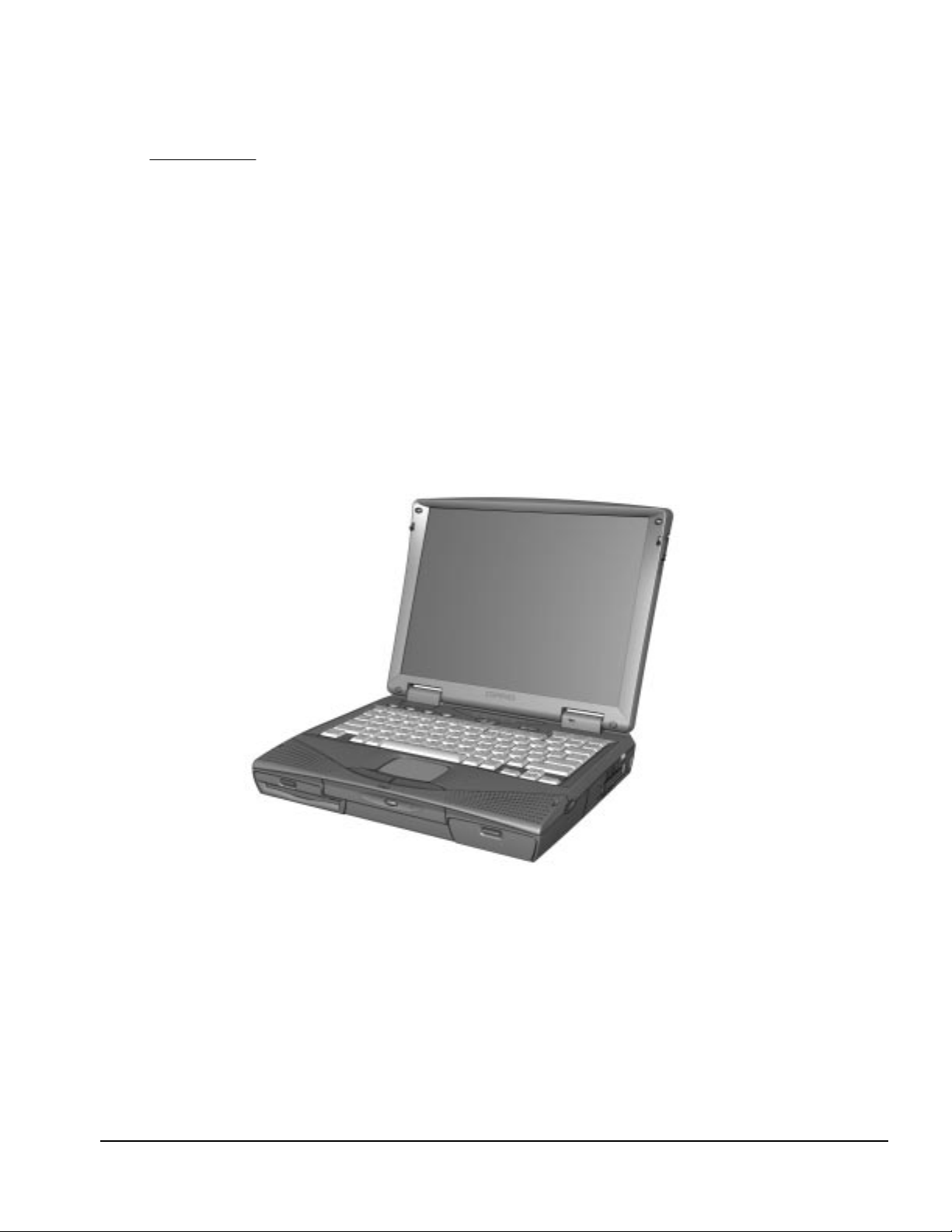
The Armada 1700 Family of Personal Computers is a line of multimedia notebook
computers with advanced modularity, processors, and video graphics. This fullfunction, Mobile Pentium II-based family of notebook computers allows full desktop
functionality and connectivity through the use of an optional Convenience Base.
Figure 1-1.
Armada 1700 Personal Computer
Product Description 1-1
Page 12

1.1.1 Features
The computer models have the following standard features:
■
233-MHz or 266-MHz Mobile Pentium II processors
■
32-MB of synchronous dynamic random access memory (SDRAM), expandable to
160 MB
■
4.0-GB, 2.5- inch internal hard drive mounted in carrier
■
LCD displays:
❏
12.1 inch SVGA CTFT display
❏
13.3-inch XGA CTFT display
■
Supports Lithium Ion (Li-ion) battery packs
■
Internal stereo speakers
■
Internal microphone
■
Full-size 101 key compatible keyboard including 12 function keys, 8 cursor control
keys, inverted-T cursor control keys, and embedded numeric keypad
■
Four user-programmable keys
■
Touchpad pointing device
■
Operates from a battery pack in the battery bay, plus an optional battery pack in the
MultiBay, or integrated AC power supply that is compatible with domestic or
international power sources
■
Power management and security features
■
Infrared interface for wireless communication with other IrDA-compliant devices at
data rates up to 4 mb/sec
■
Two standard device slots that will accommodate two Type II or one Type III PC
Card, PCMCIA card or CardBus card. The Compaq telephony modem is supported
in the top slot and Zoomed-Video in the bottom slot
■
176-pin expansion connector provides the interface to the convenience base options
■
Rear-panel ports provide connections for parallel, serial, external monitor, and
keyboard/mouse
■
Universal Serial Bus (USB)
1
(available on selected models)
1.1.2 Models
Compaq Armada 1700 computers are configurable, and may contain any or all of the
features listed. All models have 32-MB of standard memory, and may be upgraded to
160-MB.
1.1.3 Software Fulfillment
Replacement software may be ordered directly from Compaq Computer Corporation.
Both the model and the serial number of the computer are needed to identify the
specific software available.
1-2 Product Description
Page 13

1.2 Computer Options
The computer supports the following options:
■
Convenience Base II pass through model with monitor stand
■
Convenience Base II with Ethernet with monitor stand
■
Compatible with Convenience Base models from the Armada 1500 Family of
Personal Computers
■
Memory expansion boards
■
Li-ion battery pack
■
Automobile/Aircraft Adapter
■
External Battery Charger
■
PCMCIA modem
■
Hard drive upgrade
■
Hard drive adapter for MultiBay with carrying case
■
Internal modem
■
CD-ROM drive for Optical Disc Bay
■
DVD drive for optical Disc Bay
■
120-MB LS-120 diskette drive for MultiBay
■
100-MB Zip drive for MultiBay
1.2.1 Convenience Base II
Armada 1700 models support the following convenience base models:
■
Convenience Base II pass through
■
Convenience Base II with Ethernet
1.2.2 System Memory Options
The computer supports optional 16-, 32-, 64-, and 128-MB memory boards. The
memory boards are 66-MHz SDRAM without parity. System memory can be expanded
to 160-MB, depending on the model.
1
Windows 95 supports up to 115-kb/sec. Driver for 4 mb/sec available from www.microsoft.com.
Product Description 1-3
Page 14

1.2.3 External Battery Charger
The external battery charger has the following features:
■
Two battery charge slots
■
Accepts Li-ion modular batteries
■
Charges one battery in 1.5 hours
■
Charges two batteries in 3 hours
The battery calibration process should be used to discharge the batteries.
Note:
1.2.4 External Keyboards and Pointing Devices
Supports Compaq or Compaq compatible PS2 keyboards and pointing devices.
1.2.5 External Monitors
■
Supports all VGA Monitors at resolutions up to 1280 u 1024
■
Supports DDC1 and DDC2b compliant Energy Star monitors
1.3 External Computer Components
The external computer components are illustrated and described in this section.
1-4 Product Description
Page 15
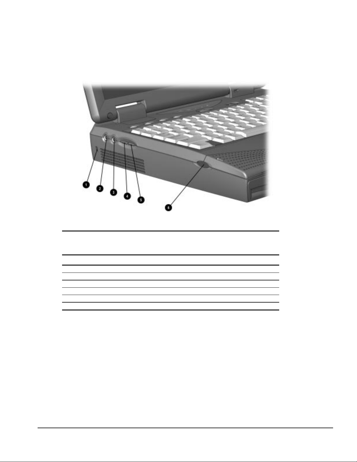
1.3.1 Left Side Components
The left side external components are shown in Figure 1-2 and are described in Table 1-1.
Figure 1-2.
Left Side Components
Table 1-1
Armada 1700 Computer Components
Left Side
Item Component Function
1
Cable Lock Secures computer to fixed object
2
Speaker/headphone jack Connects stereo speakers, headphone or headset
3
Microphone jack Connects external microphone, disables internal microphone
4
Volume up Increases volume
5
Volume down Decreases volume
6
Left bass reflex speaker port Enhances audio quality
Product Description 1-5
Page 16
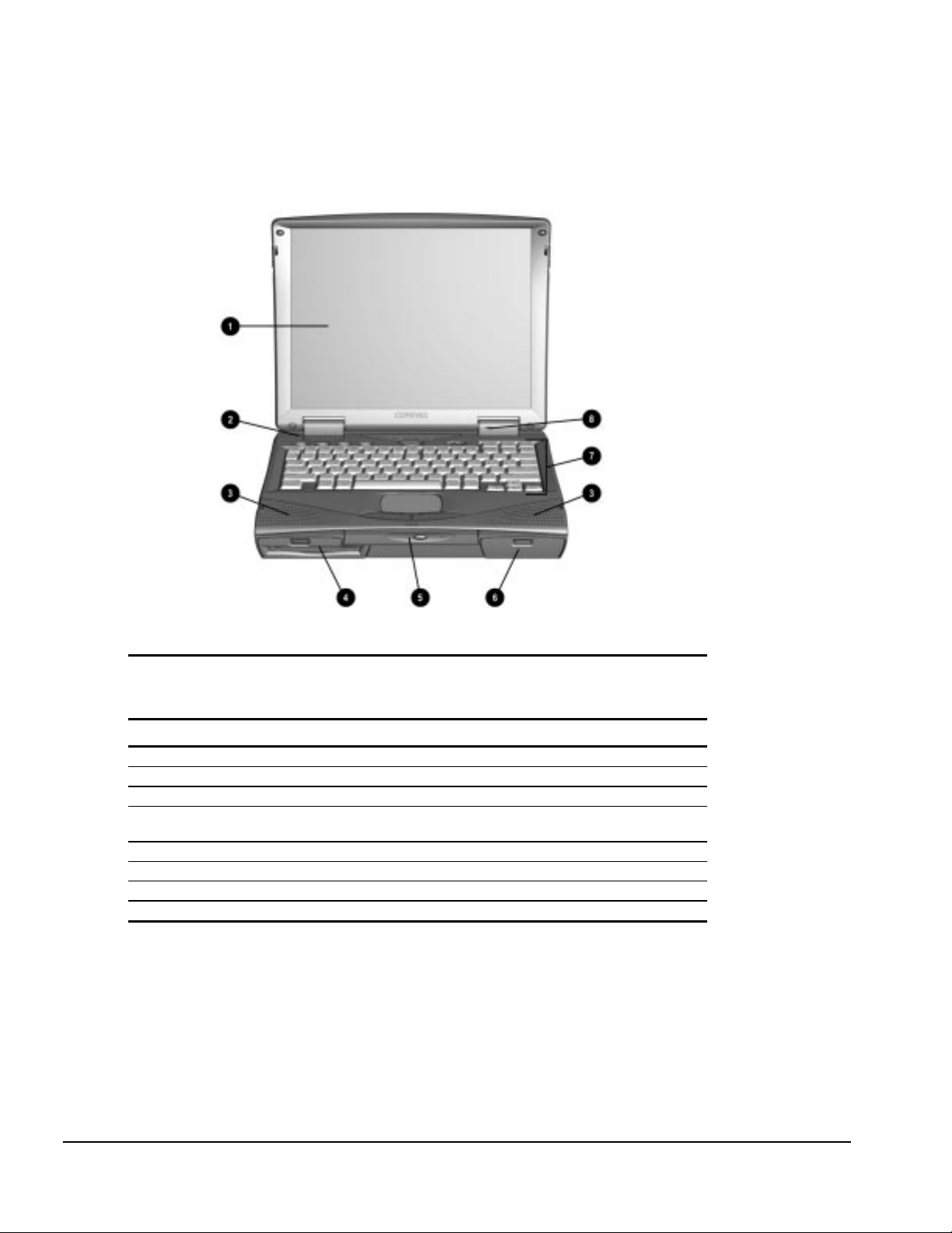
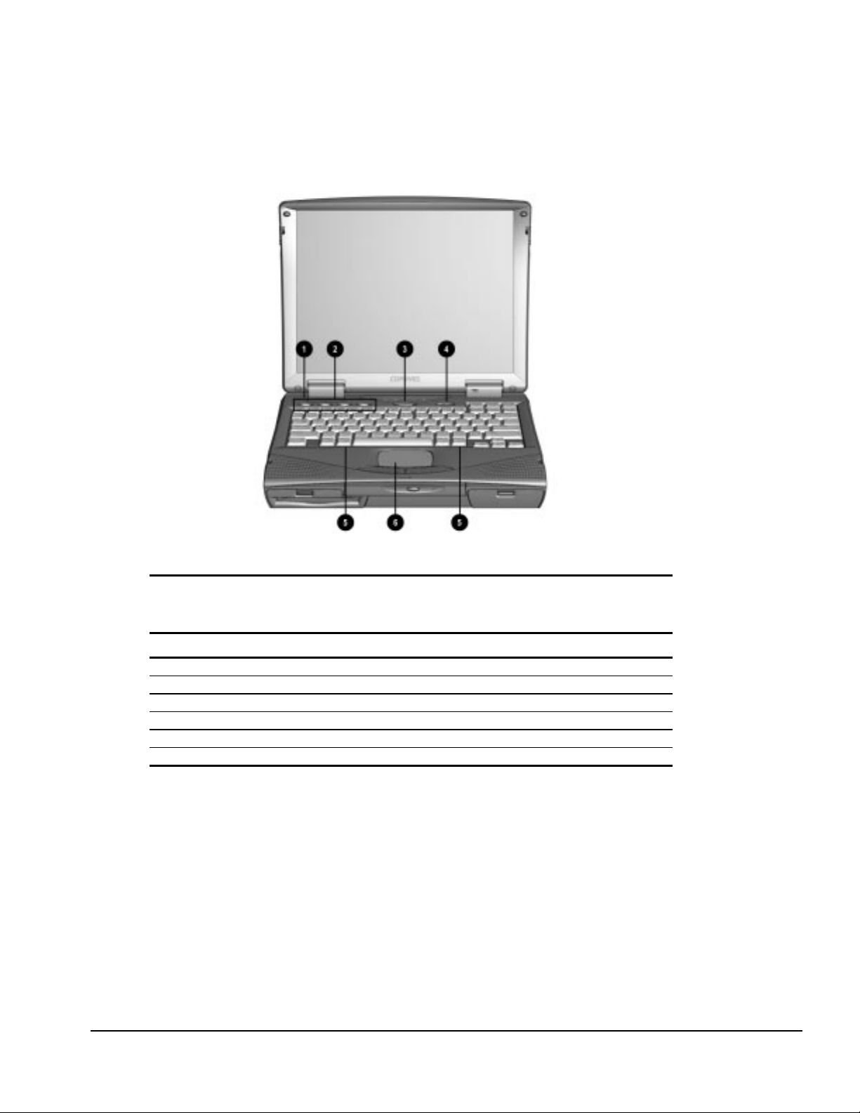
1.3.2 Front Components
The front external components are shown in Figure 1-3 and are described in Table 1-2.
Figure 1-3.
Front Components
Table 1-2
Armada 1700 Computer Components
Item Component Function
1
Display LCD graphic display
2
Lid switch Blanks display when display is closed
3
Speakers Produce high quality stereo sound
4
MultiBay Accepts diskette drive, LS-120 drive, ZIP drive, second battery
5
Optical disk bay Accepts CD-ROM or DVD-ROM devices
6
Battery bay Accepts Li-Ion battery pack
7
Keyboard Accepts operator input
8
Microphone Monophonic microphone
pack or second hard drive
Front
1-6 Product Description
Page 17
1.3.3 Top Components
The top external components are shown in Figure 1-4 and are described in Table 1-3.
Figure 1-4.
Top Components
Table 1-3
Armada 1700 Computer Components
Top
Item Component Function
1
Lid switch Blanks display when display is closed
2
Programmable function buttons User programmable keys
3
Suspend Initiates suspend
4
Power switch Turns power on and off
5
Keyboard release latched Releases keyboard from system unit
6
Touchpad Pointing device
Product Description 1-7
Page 18
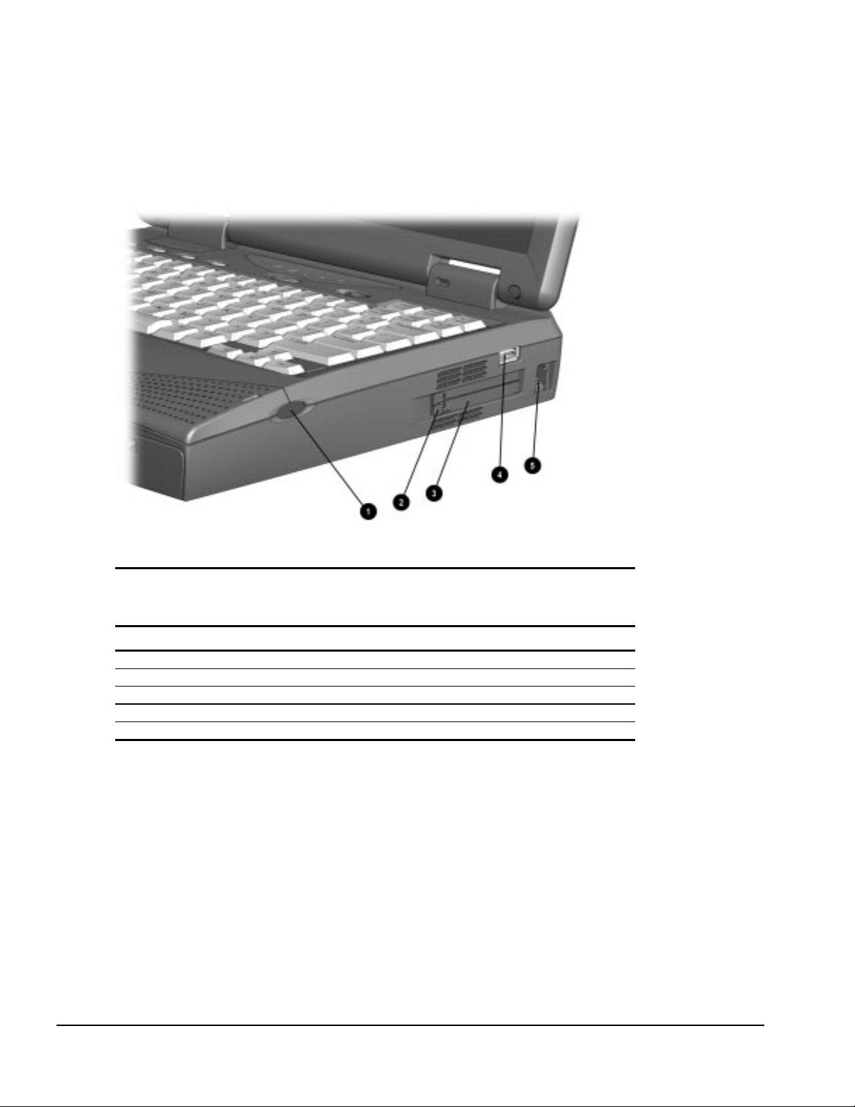
1.3.4 Right Side Components
The right side external components are shown in Figure 1-5 and are described in
Table 1-4.
Figure 1-5.
Right Side Components
Table 1-4
Armada 1700 Computer Components
Right Side
Item Component Function
1
Right bass reflex speaker port Enhances audio quality
2
PC Card eject button Eject PC Cards from the slots
3
PC Card slots Accepts 16- and 32-bit PC Cards
4
USB Connector Connects USB devices to the computer
5
Modem jack Connects the phone line to the computer (selected models)
1-8 Product Description
Page 19
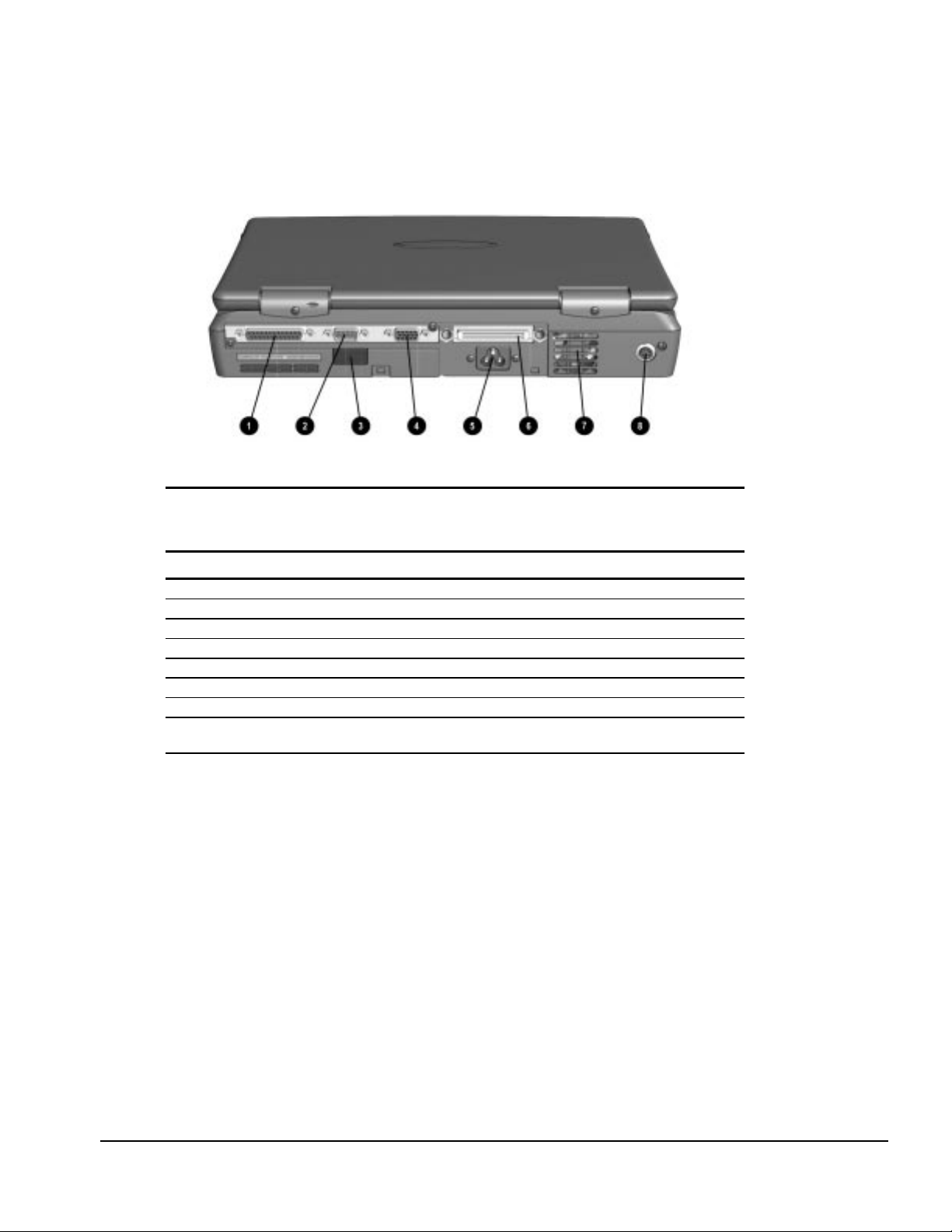
1.3.5 Rear Components
The rear components are shown Figure 1-6 and are described in Table 1-5.
Figure 1-6.
Rear Components
Table 1-5
Armada 1700 Computer Components
Item Component Function
1
Parallel connector Connects parallel devices such as a printer
2
Serial connector Connects serial devices such as a mouse
3
Infrared port Provides wireless communications (on selected models)
4
External monitor connector Connects external monitor
5
AC Power connector Connects external AC power
6
Docking connector Provides connection to optional convenience base
7
Fan (Airflow vents) Provides thermal ventilation to internal components
8
External Keyboard Connects external keyboard or PS-2 mouse
(Supports standard Y connector)
Rear
Product Description 1-9
Page 20
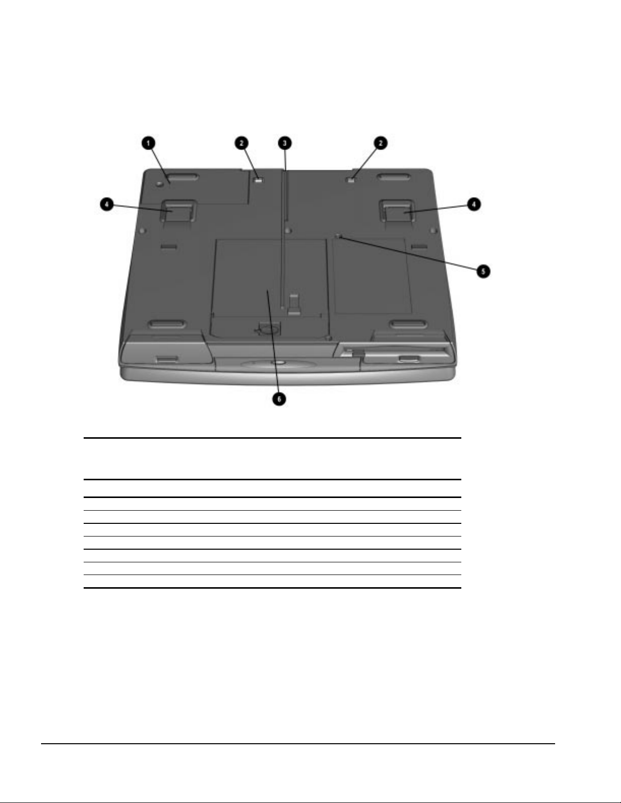
1.3.6 Bottom Components
The bottom external components are shown in Figure 1-7 and are described in
Table 1-6.
Figure 1-7.
Bottom Components
Table 1-6
Armada 1700 Computer Components
Bottom
Item Component Function
1
Modem compartment Integrated modem (selected models)
3
Docking alignment guide Aligns computer to optional convenience base
2
Docking latch receptacles Locks computer to optional convenience base
4
Tilt feet Adjusts computer to an angle
5
MultiBay screw Secures MultiBay Devices
6
Hard drive cover Covers hard drive compartment
* Hard drive security screw Secures hard drive cover (not shown)
1-10 Product Description
Page 21
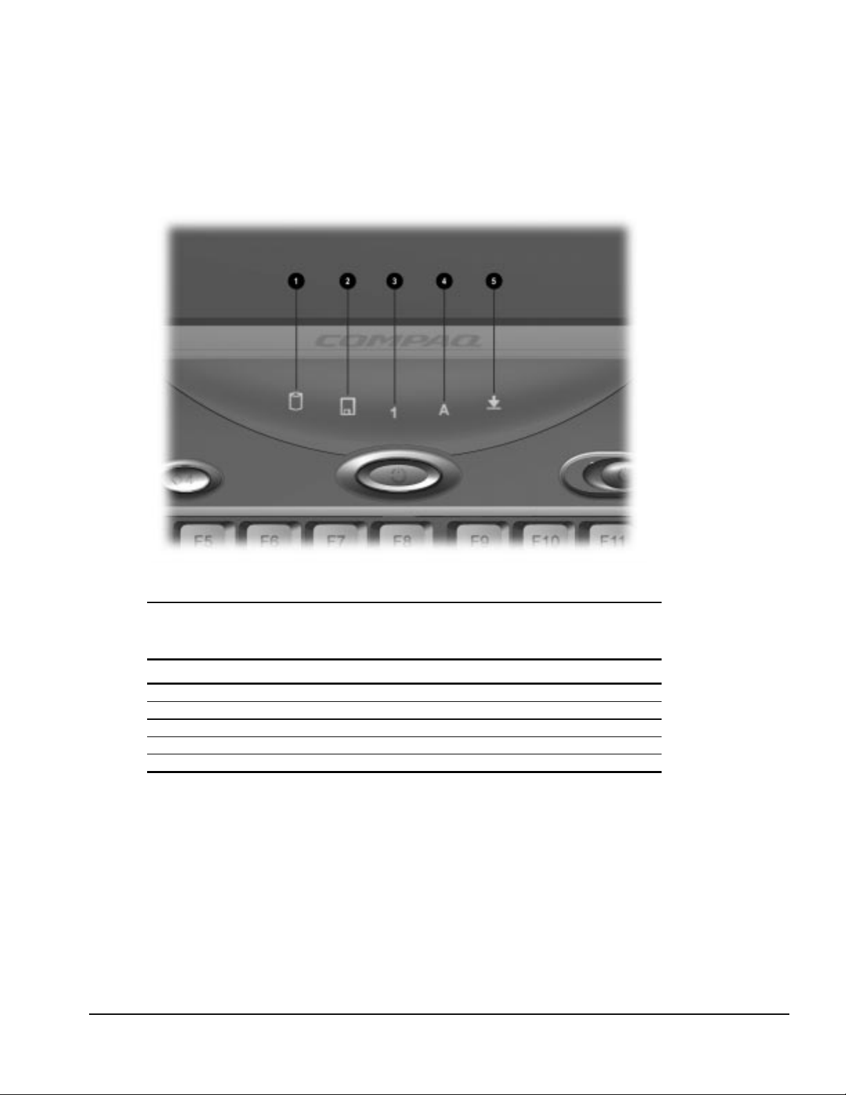
1.3.7 Status Panel Lights
The status panel lights are shown in Figure 1-8 and described in
Table 1-7.
Figure 1-8.
Status Panel Lights
Table 1-7
Armada 1700 Computer Components
Status Panel
Item Component Function
1
Hard drive activity light Indicates hard drive or CD-ROM access
2
MultiBay activity light Indicates MultiBay device activity
3
Number lock indicator Indicates that numbers lock is on
4
Caps lock indicator Indicates that caps lock is on
5
Scroll lock indicator Indicates that scroll lock is on
Product Description 1-11
Page 22

1.4 Design Overview
This section presents a design overview of the computer. The overview is limited to
field replaceable parts. All replacement parts are listed in Chapter 3.
1.4.1 System Unit
The computer is a traditional clamshell design with a display assembly attached to a
system unit. The computer opens to reveal a backlit LCD display and a full-function
keyboard. The display is designed for a continuously adjustable tilt angle.
1.4.2 Internal Boards
The system electronics are integrated on four printed circuit assemblies: the audio/led
board, system board, modem board, and the DC-DC converter board.
■
The audio/led board provides support for the audio functions.
■
The system board integrates the processor, on-board memory, level 2 cache, local
bus video adapter, and PCMCIA/CardBus adapter.
■
The optional modem board supports data or fax functions.
■
The DC-DC converter board creates the system voltages (3.3v and 5v) from the
battery or AC/DC input.
Processor
An Intel Mobile Pentium II processor is located on the system board for the 233 MHz
and 266 MHz models.
Memory
Base memory is 32-MB with 16-, 32-, 64-, or 128-MB of optional expansion memory.
Base memory is onboard memory built into the system board. Expansion memory
consists of one memory expansion board available as a user installable option.
Cache
Level 2 cache is integrated in the CPU module. It is not user upgradable.
PCMCIA/CardBus and Video Adapter Controller
The PCMCIA/CardBus adapter is based on the Texas Instrument PCI1220 PC to
CardBus controller unit. The local bus video adapter is the Chips and Technologies
65555 controller.
■
The serial-parallel port board expands the serial and parallel signals from the system
board to the serial and parallel expansion connectors.
■
The audio/led board supports the microphone and headphone jacks, the volume
control switches, and the amplifier and equalization circuitry.
1-12 Product Description
Page 23

1.4.3 Video system
The standard video subsystem consists of:
■
An internal LCD Display
■
12.1 inch SVGA CTFT display
■
13.3 inch XGA CTFT display
■
2 Megabyte frame buffer
■
An inverter to supply AC power to the LCD back-light system
■
A standard external VGA connector for use with CRTs and other VGA compatible
displays
■
40 KByte Video ROM
Product Description 1-13
Page 24

1-14 Product Description
Page 25

chapter
2
ROUBLESHOOTING
T
Follow these basic steps when beginning the troubleshooting process:
1. Complete the preliminary steps listed in Section 2.1.
2. Run the Power-On Self-Test (POST) as described in Section 2.3.
3. Run Computer Setup as described in Section 2.5.
4. Run the Computer Checkup (TEST) as described in Section 2.6.
5. If you are unable to run POST or Computer Checkup or if the problem persists after
running POST and Computer Checkup, perform the recommended actions
described in the diagnostic tables in Section 2.5.
Follow these guidelines when troubleshooting:
Complete the recommended actions in the order in which they are given.
■
Repeat POST and Computer Checkup after each recommended action until the
■
problem is resolved and the error message does not return.
When the problem is resolved, stop performing the troubleshooting steps and do not
■
complete the remaining recommended actions.
Refer to Chapter 5 for removal and replacement procedures that are recommended.
■
If the problem is intermittent, check the computer several times to verify that the
■
problem is solved.
The following table describes the troubleshooting actions:
If You Want To: Then Run:
Check for POST error messages POST
Check that computer components are recognized and
running properly
View information about the computer and installed or
connected devices
Perform any of the following:
Check the system configuration
■
Set the system power management parameters
■
Return the system to its original configuration
■
Check system configuration of installed devices
■
Computer Checkup (TEST) under Compaq Utilities
View System Information (INSPECT) under
Compaq Utilities
Computer Setup
Troubleshooting 2-1
Page 26

2.1 Preliminary Steps
IMPORTANT:
Checkup. A low battery condition could initiate Hibernation and interrupt the test.
Before running POST and Computer Checkup, complete the following steps:
1. Obtain established passwords. If you must clear the passwords, go to Section 2.2.
2. Ensure that the hard drive is installed in the computer.
3. Ensure that the battery pack is installed in the computer and the power cord is
connected to the computer and plugged into an AC power source.
4. Turn on the computer.
5. If a power-on password has been established, type the password and press
6. Run Computer Setup (Section 2.5). If a Setup password has been established, type
the password and press
7. Turn off the computer and all external devices.
8. Disconnect external devices that you do not want to test. If you want to use the
printer to log error messages, leave it connected to the computer.
NOTE:
the problem could be with the external device or its cable. Isolate the problem by
running POST with and without the external device connected.
9. Use Compaq Utilities and loopback plugs in the serial and parallel connectors if you
plan to test these ports.
Follow these steps to run Compaq Utilities:
Use AC power when running POST, Computer Setup, or Computer
Enter.
Enter.
If a problem only occurs when an external device is connected to the computer,
a. If you are running Compaq Utilities from the hard drive, turn on or restart the
computer. Press
screen. If you do not press
If you are running Compaq Utilities from diskette, insert the Compaq Utilities
diskette in drive A. Turn on or restart the computer.
b. Press
c. Select Computer Checkup (TEST).
d. Select Prompted Diagnostics.
e. After “Identifying System Hardware” completes, select Interactive Testing and
follow the instructions on the screen.
Enter
to accept
when the cursor appears in the upper right corner of the
F10
in time, restart the computer and try again.
F10
.
OK
2-2 Troubleshooting
Page 27

2.2 Clearing Passwords
The power-on password prevents use of the computer until the password is entered. The
setup password prevents unauthorized changes to Computer Setup. To clear the
passwords, you must remove all power from the system board. If you do not know the
passwords, use the following procedure to clear the password:
1. Remove all battery packs from the battery bay and MultiBay, if applicable.
2. Disconnect the AC power.
3. Remove the real-time clock battery.
4. Wait five minutes.
5. Reconnect the AC power.
6. Restart the computer. During Power-On Self Test (POST), a “162 System Options
not set” message appears.
7. Shut down the computer, then disconnect AC power again.
8. Replace the real-time clock battery.
9. Install the battery pack(s).
10. Proceed with the troubleshooting procedures.
2.3 Power-On Self-Test (POST)
The Power-On Self-Test (POST) is a series of tests that run every time the computer is
turned on. POST verifies that the system is configured and functioning properly.
To run POST, complete the following steps:
1. Complete the preliminary steps (Section 2.1).
2. Turn on the computer.
If POST does not detect any errors, the computer beeps once or twice to indicate that
POST has run successfully. The computer boots from the hard drive or from a bootable
diskette if one is installed in the diskette drive.
2.4 POST Error Messages
If the system is not functioning well enough to run POST, or if the display is not
functioning well enough to show POST error messages, refer to the Troubleshooting
tables in Section 2.6.
If POST detects an error, one of the following events occurs:
A message with the prefix "WARNING" appears informing you where the error
■
occurred. The system pauses until you press F1 to continue.
A message with the prefix "FATAL" appears informing you where the error
■
occurred. After the message, the system emits a series of beeps and stops.
The system emits a series of beeps and stops.
■
Troubleshooting 2-3
Page 28

Warning messages indicate that a potential problem, such as a system configuration
error, exists. When F1 is pressed, the system should resume. You should be able to
correct problems that produce WARNING messages.
IMPORTANT:
to run Computer Setup. (Computer Setup replaces the SCU utility.)
F10
When a WARNING message includes the prompt to "RUN SCU," press
2-4 Troubleshooting
Page 29

If you receive one of the error messages listed below, follow the recommended action.
Table 2-1
Warning Messages
Message Description Recommended Action
CMOS checksum invalid, run SCU CMOS RAM information has
been corrupted.
CMOS failure, run SCU CMOS RAM has lost power. Run Computer Setup to reinitialize
Diskette controller error The diskette drive controller
failed to respond to the
recalibrate command.
Diskette track 0 failed The diskette drive cannot read
track 0 of the diskette in the
drive.
Hard disk controller error The hard drive controller failed
to respond to the reset
command.
Keyboard controller failure The keyboard failed the self-
test command.
Keyboard failure The keyboard failed to respond
to the RESET ID command.
No interrupts from Timer 0 The periodic timer interrupt is
not occurring.
ROM at xxxx (LENGTH yyyy) with
nonzero checksum (zz)
Time/Date corrupt - run SCU The time and date stored in the
Hard disk xx failure (or error) A failure or an error occurred
Unsupported memory module An EDO memory module was
An illegal adapter ROM was
located at the specified
address.
real time clock have been
corrupted, possibly by a power
loss.
when trying to access the hard
drive.
installed in the memory
expansion slot.
Run Computer Setup to reinitialize
CMOS-RAM.
CMOS-RAM.
If there is no diskette drive in the
system, run Computer Setup to
properly configure the CMOS-RAM to
show no diskette drive present. If the
problem persists, or if a diskette drive
is present, complete these steps until
the problems is solved:
1. Check diskette drive connections.
2. Replace diskette drive.
3. Replace system board.
Try another diskette. If the problem
persists, you may need to replace the
diskette drive.
Check the drive parameters. Turn off
the system and check all related
connections.
Replace the system board.
Replace the keyboard. If the problem
persists, replace the system board.
Replace the system board.
Check the external adapter (such as a
video card) to determine if it is
causing the conflict.
1. Run Computer Setup.
2. If problem persists, replace
auxiliary battery.
3. If problems persists, replace
system board.
1. Run Scan disk.
2. Check disk in DOS and
Windows 95. If problem persists,
refer to Table 2-10.
Remove the EDO memory module
and replace with SDRAM memory
module.
Troubleshooting 2-5
Page 30

Fatal errors emit a beep and may display a FATAL message. Fatal errors indicate severe
problems, such as a hardware failure. Fatal errors do not allow the system to resume.
Some of the Fatal error beep codes are listed at the end of this section.
Table 2-2
Fatal Error Messages
Message Description Beep Code
CMOS RAM test failed A walking bit test of CMOS RAM location 0E
(Hex) - 3F (Hex) failed.
DMA controller faulty A sequential read/write of the transfer count
and transfer address registers within the
primary and secondary DMA controllers failed.
Faulty DMA page registers A walking bit read/write of the 16 DMA
controller page registers starting at location
80 Hex failed.
Faulty refresh circuits A continuous read/write test of port 61h found
that bit 4 (Refresh Detect) failed to toggle
within an allotted amount of time.
Interrupt controller failed A sequential read/write of various Interrupt
Controller registers failed.
ROM checksum incorrect A checksum of the ROM BIOS does not match
the byte value at F000:FFFF.
RAM error at location xxxx RAM error occurred during memory test. None
3
4
0
1
5
2
Table 2-3
Fatal Error Beep Codes
Beep Code Beep Sequence Description Recommended Action
0 S-S-S-P-S-S-L-P The DMA page registers are
faulty.
1 S-S-S-P-S-L-S-P The refresh circuitry is faulty.
2 S-S-S-P-S-L-L-P The ROM checksum is incorrect.
3 S-S-S-P-L-S-S-P The CMOS RAM test failed.
4 S-S-S-P-L-S-L-P The DMA controller is faulty.
5 S-S-S-P-L-L-S-P The interrupt controller failed.
6 S-S-S-P-L-L-L-P The keyboard controller failed.
7 S-S-L-P-S-S-S-P Graphics adapter is faulty.
8 S-S-L-P-S-S-L-P Internal RAM is faulty. Replace memory board or
Replace system board.
system board if memory on
system board is faulty.
S = Short, L = Long, P = Pause
2-6 Troubleshooting
Page 31

2.5 Compaq Utilities
Compaq Utilities contain several functions that
Determine if various computer devices are recognized by the system and are
■
operating properly.
Provide information about the system once it is configured.
■
Compaq Utilities include the following programs:
Computer Setup
■
Computer Checkup (TEST)
■
View System Information (INSPECT)
■
To access Compaq Utilities:
1. Turn on or restart the computer by clicking Start ⇒ Shut Down ⇒ Restart the
computer.
2. Press
3. Select a menu option.
Computer Setup
Computer Setup contains utilities that give you an overall picture of the computer
hardware configuration and aid in troubleshooting. These utilities also allow you to set
custom features such as security options, power conservation levels, and startup
preferences.
when the blinking cursor appears in the upper-right corner of the display.
F10
If you are running Windows 95, the computer automatically recognizes and configures
the system for new devices. If you have a configuration problem or want to view or
reset configuration settings, you can use Computer Setup.
If you are running Windows 95, you should use Computer Setup only to adjust
NOTE:
system features such as the power-on password or battery conservation level. Windows
95 may override other configuration changes.
If you are running Windows NT, the computer does not automatically recognize new
devices added to the system. All devices ordered with your system have been
configured for you. Use Computer Setup to view settings for a new device you have
added or to reset configuration settings for preinstalled devices.
Computer Setup provides two methods of viewing the computer configuration: by type
(factory setting) or connection.
Troubleshooting 2-7
Page 32

Categories by type:
System Features—security, power, boot management
■
Communication—port, modem, and other communication devices
■
Storage—storage-related devices such as hard drive, CD-ROM drive, diskette drive
■
Input Devices—keyboard, mouse, and other input devices
■
Network—network adapter or other network-related devices
■
Audio—sound properties and audio device settings
■
Video—display timeouts and video device resources
■
Other—miscellaneous devices
■
Categories by connection:
System Features—security, power, boot management
■
System Devices—keyboard, mouse, parallel and serial ports
■
ISA—ISA bus and connected devices
■
PCI—PCI bus and connected devices
■
PC Card—PC Card devices
■
Running Computer Setup
1. Turn on or restart the computer by clicking Start ⇒ Shut Down ⇒ Restart the
computer.
2. Press
NOTE:
3. Click a language and press
4. Click Computer Setup and press
5. When you are finished, click
when the blinking cursor appears in the upper-right corner of the screen.
F10
If you a setup password is enabled, it must be used to access Computer Setup.
Enter.
.
Enter
Exit.
2-8 Troubleshooting
Page 33

Exiting Computer Setup
1. Click
Exit.
2. Select one of the following Exit options:
Save—Saves the new settings and exits Computer Setup.
■
: Some settings may not take effect until the computer is restarted.
NOTE
Ignore—Exits Computer Setup and restores previous settings.
■
Cancel—Returns to Computer Setup.
■
Computer Checkup (TEST)
Computer Checkup (TEST) determines whether the various computer components and
devices are recognized by the computer and are functioning properly. You can display,
print, or save the information that Computer Checkup generates.
NOTE:
Compaq Utilities are intended for testing only Compaq-supplied components.
Testing of non-Compaq components may be inconclusive.
Running Computer Checkup (TEST)
1. Plug the computer into an external power source. A low battery condition can
interrupt the program.
2. Connect a printer if you want to print a log of error messages.
3. Turn on the external devices that you want to test.
4. Turn on or restart the computer.
5. Access Compaq Utilities by pressing
upper-right corner of the display.
6. Click Computer Checkup ⇒ View the Device List.
If the list of installed devices is correct, click
■
If the list is incorrect, ensure that any new devices are installed properly.
■
7. Select one of the following from the Test Option menu:
Quick Check Diagnostics
■
when the blinking cursor appears in the
F10
OK.
Automatic Diagnostics
■
Prompted Diagnostics
■
8. Follow the instructions on the screen as the devices are tested.
9. Click Exit Diagnostics ⇒ Exit from this utility.
Troubleshooting 2-9
Page 34

Computer Checkup (TEST) Error Codes
Computer Checkup (TEST) error codes occur if the system recognizes a problem while
running Computer Checkup. These error codes help identify possible defective
assemblies. Tables 2-4 through 2-14 list Computer Checkup error codes, a description
of the error condition, and the recommended action for resolving the condition. For
removal and replacement procedures, refer to Chapter 5.
IMPORTANT
: Run Computer Checkup each time you complete a recommended action
step. If the problem is resolved when POST and Computer Checkup are rerun (i.e., with
no error codes), do not perform the remaining recommended action steps.
: The error codes in the following tables are listed in an “AYE-XX” format,
NOTE
where:
A or AA = Number that represents the faulty assembly
YY = Test or action that failed
XX = Specific problem
Table 2-4
Processor Test Error Codes
Error Code Description Recommended Action
101-xx CPU test failed. Replace the processor board and retest.
103-xx DMA page registers test failed. Replace the system board and retest.
104-xx Interrupt controller master test failed.
105-xx Port 61 error.
106-xx Keyboard controller self-test failed.
107-xx CMOS RAM test failed.
108-xx CMOS interrupt test failed.
109-xx CMOS clock test failed.
110-xx Programmable timer load data test failed.
113-xx Protected mode test failed.
2-10 Troubleshooting
Page 35

Table 2-5
Memory Test Error Codes
Error Code Description Recommended Action
200-xx Memory machine ID test failed. The following steps apply to error codes 200-xx
and 202-xx:
202-xx Memory system CMOS checksum failed.
203-xx Write/Read test failed. The following applies to error codes 203-xx
204-xx Address test failed. Remove and replace the SODIMM memory board
211-xx Random pattern test failed.
214-xx Noise test failed.
215-xx Random address test failed.
1. Flush the system CMOS and retest. See note.
2. Replace the system board and retest.
through 215-xx:
or system board (if the memory on the system
board is faulty) and retest.
Table 2-6
Keyboard Test Error Codes
Error Code Description Recommended Action
300-xx Failed ID Test.
301-xx Failed Self test/Interface Test.
302-xx Failed Individual Key Test.
1. Reseat the keyboard assembly.
2. Replace the keyboard and retest.
3. Replace the system board and retest.
304-xx Failed Keyboard Repeat Test.
Table 2-7
Parallel Printer Test Error Codes
Error Code Description Recommended Action
401-xx Printer failed or not connected.
402-xx Failed Port Test.
403-xx Printer pattern test failed.
1. Connect the printer.
2. Check power to the printer.
3. Install the loopback connector and retest.
4. Check port and IRQ configuration.
5. Replace the system board and retest.
Fn + F11 clears the ESCD configuration information. If the Fn + F11 sequence is
Note:
pressed very early after powering the machine on (after you see the keyboard LEDs
blink, but before the video is initialized), CMOS memory will be invalidated. The
ESCD is cleared, the machine is reset and boots with the "162 - System Options Not
Set" message. This is a way to clear out configuration information, such as Windows
95's knowledge about a docking station. It may help clear up problems if the
configuration information had been corrupted. Timing of this keystroke sequence is
critical, as there is a very narrow window during which the keys will be recognized.
These keys are not documented to users.
Troubleshooting 2-11
Page 36

Table 2-8
Diskette Drive Error Codes
Error Code Description Recommended Action
600-xx Diskette ID drive types test
failed.
601-xx Diskette format failed. 1. Replace the diskette.
602-xx Diskette read test failed. 2. Replace the diskette drive and retest.
603-xx Diskette write, read, compare test failed. 3. Replace the system board and retest.
604-xx Diskette random read test failed.
605-xx Diskette ID media test failed.
606-xx Diskette speed test failed.
609-xx Diskette reset controller test failed.
610-xx Diskette change line test failed.
697-xx Diskette type error.
698-xx Diskette drive speed not within limits.
699-xx Diskette drive/media ID error. 1. Replace media.
The following steps apply to error codes 600-xx
through 698-xx:
2. Run Compaq Utilities.
Table 2-9
Serial Test Error Codes
Error Code Description Recommended Action
1101-xx Serial port test failed. 1. Check port configuration.
2. Replace the system board and retest.
Table 2-10
Hard Drive Test Error Codes
Error Code Description Recommended Action
1701-xx Hard drive format test failed.
1702-xx Hard drive read test failed.
1703-xx Hard drive write/read/compare test failed. 3. Replace the hard drive and retest.
1704-xx Hard drive random seek test failed. 4. Replace the system board and retest.
1705-xx Hard drive controller test failed.
1706-xx Hard drive ready test failed.
1707-xx Hard drive recalibration test failed.
1708-xx Hard drive format bad track test failed.
1709-xx Hard drive reset controller test failed.
1710-xx Hard drive park head test failed.
1715-xx Hard drive head select test failed.
1716-xx Hard drive conditional format test failed.
1717-xx Hard drive ECC* test failed.
1719-xx Hard drive power mode test failed.
1724-xx Network preparation test failed.
1736-xx Drive monitoring test failed.
* ECC = Error Correction Code
1. Run Compaq Utilities and verify drive type.
2. Verify that all secondary drives have
secondary drive capability.
2-12 Troubleshooting
Page 37

Table 2-11
Video Test Error Codes
Error Code Description Recommended Action
501-xx Video controller test failed. The following actions apply to error codes 501-xx
502-xx Video memory test failed. 1. Disconnect external monitor and test with
503-xx Video attribute test failed. 2. Replace the display assembly and retest.
504-xx Video character set test failed. 3. Replace the system board and retest.
505-xx Video 80 × 25 mode 9 × 14 character
cell test failed.
506-xx Video 80 × 25 mode 8 × 8 character
cell test failed.
507-xx Video 40 × 25 mode test failed.
511-xx Video screen memory page test failed.
512-xx Video gray scale test failed.
514-xx Video white screen test failed.
516-xx Video noise pattern test failed.
2402-xx Video memory test failed. The following actions apply to error codes
2403-xx Video attribute test failed. 1. Run Compaq Utilities.
2404-xx Video character set test failed. 2. Disconnect external monitor and test with
2405-xx Video 80 × 25 mode 9 × 14 character cell
test failed.
2406-xx Video 80 × 25 mode 8 × 8 character cell
test failed.
2411-xx Video screen memory page test failed.
2412-xx Video gray scale test failed.
2414-xx Video white screen test failed.
2416-xx Video noise pattern test failed.
2418-xx ECG/VGC memory test failed.
2419-xx ECG/VGC ROM checksum test failed.
2421-xx ECG/VGC 640 × 200 graphics mode test
failed.
2422-xx ECG/VGC 640 × 350 16 color set test
failed.
2423-xx ECG/VGC 640 × 350 64 color set test
failed.
2424-xx ECG/VGC monochrome text mode test
failed.
2425-xx ECG/VGC monochrome graphics mode test
failed.
2431-xx 640 × 480 graphics test failed.
2448-xx Advanced VGA Controller test failed.
through 516-xx:
internal LCD display.
2402-xx through 2456-xx:
internal LCD display.
3. Replace the display assembly and retest.
4. Replace the system board and retest.
Continued
Troubleshooting 2-13
Page 38

Table 2-11
Continued
Error Code Description Recommended Action
2451-xx 132-column Advanced VGA test failed.
2456-xx Advanced VGA 256 Color test failed.
2458-xx Advanced VGA Bit BLT test failed. The following step action to error codes 2458-xx
to 2480-xx:
2468-xx Advanced VGA DAC test failed. Replace the system board and retest.
2477-xx Advanced VGA data path test failed.
2478-xx Advanced VGA BitBLT test failed.
2480-xx Advanced VGA Linedraw test failed.
Refer to Table 2-25 for information about other video errors.
Table 2-12
Audio Test Error Codes
Error Code Description Recommended Action
114-01 Speaker test failed.
3206-xx Audio System Internal Error Replace the audio board and retest.
1. Check system configuration.
2. Verify verify that the audio/led board is properly
seated.
3. Verify display audio cable connection.
Table 2-13
Pointing Device Interface Test Error Codes
Error Code Description Recommended Action
8601-xx Pointing device test failed.
8602-xx Interface test failed.
Replace the keyboard/CPU cover assembly.
Table 2-14
CD-ROM Test Error Codes
Error Code Description Recommended Action
3301-xx CD-ROM drive read test failed.
3305-xx CD-ROM drive seek test failed.
6600-xx ID test failed.
6605-xx Read test failed.
6608-xx Controller test failed.
6623-xx Random read test failed.
1. Replace the CD and retest.
2. Verify that drivers are loaded and properly
installed.
3. Replace the CD-ROM drive and retest.
4. Replace the system board and retest.
2-14 Troubleshooting
Page 39

Running View System Information (INSPECT)
The View System Information (INSPECT) utility provides information about the
computer and installed or connected devices. You can display, print, or save the
information.
In order to access the INSPECT utility, follow the instructions below:
1. Connect a printer if you want to print the INSPECT information.
2. Turn on or restart the computer.
3. Access Compaq Utilities by pressing
corner of the display.
4. If prompted, select a language.
5. Click View System Information (INSPECT).
6. Click the item you want to view. The list includes the following:
■ System ■ Audio
■ ROM ■ Operating system
■ Keyboard ■ System files
■ System ports ■ Windows files
■ System storage ■ Miscellaneous
■ Graphics
■ Memory
7. Follow the instructions on the screen to cycle through the screens, to return to the
list and choose another item, or to print the information.
8. Select Exit Inspect.
when the cursor blinks in the upper-right
F10
■ Network (applicable only if
computer is docked in the
Convenience Base II)
Troubleshooting 2-15
Page 40

Running Compaq Diagnostics
Compaq Diagnostics provides computer component information when the operating
system is working.
If you are running Windows 95, access Compaq Diagnostics for Windows by
double-clicking My Computer ⇒ Control Panel ⇒ Compaq Diagnostics.
Boot Sequencing
1. Run Computer Setup.
2. Click the System Features icon ⇒ Boot Management box ⇒ MultiBoot tab.
3. Designate the hard drive boot (startup) sequence you want.
4. Click OK to accept the changes.
Factory Default Settings
Initialization
Enable POST Memory Test Checked (enabled)
Keyboard num Lock Unchecked (Off)
1 Hard drive in the computer
2 Hard drive in the computer MultiBay
Boot display Auto
Language Language of country
Ports
Serial/infrared ports
Serial port 3F8, IRQ4
Infrared port 2F8, IRQ3
Parallel port 378, IRQ7
Ethernet port 300, IRQ9
2-16 Troubleshooting
Page 41

Power
Low Battery Warning Beep Checked (enabled)
External Energy Saving Monitor Connected Unchecked (not connected)
Power Management
Enabled While operating power on battery
Conservation Level Medium
Level Definition
High Suspend Time: 5 minutes
Hibernation Timeout: Immediate
Drive Timeout: 2 minutes
Screen Timeout: 2 minutes
Medium Suspend Time: 10 minutes
Hibernation Timeout: 1 hour
Drive Timeout: 6 minutes
Screen Timeout: 4 minutes
Custom Suspend Time: disabled
Hibernation Timeout: low battery
Drive Timeout: always on
Screen Timeout: always on
Security
Enable QuickLock/QuickBlank Unchecked (Disabled)
Enable Power-On Password Unchecked (Disabled)
Disable Serial/Infrared Ports Unchecked (Enabled)
Disable Parallel Port Unchecked (Enabled)
Disable PC Card Slots Unchecked (Enabled)
Setup Password Password blank
Power-On Password Password blank
Diskette Drives
Disable Diskette Drives Unchecked (Enabled)
Disable Diskette Boot Unchecked (Enabled)
Troubleshooting 2-17
Page 42

2.6 Troubleshooting Without Diagnostics
This section provides information about how to identify and correct some common
hardware, memory, and software problems. It also explains several types of messages
that may be displayed on the screen.
Since symptoms can appear to be similar, carefully match the symptoms of the computer
malfunction against the problem description in the Troubleshooting tables to avoid a
misdiagnosis.
Before Replacing Parts
When troubleshooting a problem, check the following items for possible solutions
before replacing parts:
Verify that cables are connected properly to the suspected defective parts.
■
Verify that all required device drivers are installed.
■
Verify that all printer drivers have been installed.
■
Checklist for Solving Problems
If you encounter a minor problem with the computer or software applications, go
through the following checklist for possible solutions:
Is the computer connected to an external power source, or does it have a fully
■
charged battery pack installed?
Are all cables connected properly and securely?
■
Did the diskette drive contain a nonbootable diskette when you turned on the
■
computer?
Have you installed all the needed device drivers? For example, if you are using a
■
mouse, you may need to install a mouse device driver.
Are printer drivers installed?
■
Eliminating the typical problems described in this Troubleshooting section may save
you time and money. If the problem appears related to a software application, check the
documentation provided with the software. You may discover something you can
resolve easily by yourself.
2-18 Troubleshooting
Page 43

Solving Audio Problems
Table 2-15
Solving Audio Problems
Problem Probable Cause Recommended Action(s)
Computer does not beep after
the Power-On Self-Test
(POST).
Computer beeped five times
and battery light is blinking.
Computer does not beep to
indicate a low-battery
condition.
Audio playback is too low or
too loud.
Internal speakers produce no
sound.
Speaker volume has been
turned down.
Computer has entered a
low-battery condition.
Low-battery warning beeps
have been turned off.
System beeps have been
turned down too low.
The computer volume control
and/or the software volume
control needs to be adjusted.
Volume has been muted. Press the increase volume control button to
External speakers or
headphones are connected to
the computer.
Speaker wires are not
connected.
Speakers are bad. Replace the speakers.
Adjust the volume with the volume control
buttons located at the top right corner of the
computer.
Immediately save open files and resolve the
low battery condition.
Enable low-battery warning beeps in
Windows 95 Power Properties or in
Computer Setup power management.
Press
to increase the volume of the system beeps.
In Windows 95, adjust the computer volume
control buttons and adjust the volume
control in Multimedia Properties.
NOTE
Properties only affects the Wave audio
sources such as system sounds and *.wav
file playback. To change other sources such
as MIDI, video sound, and game effects, use
the Volume Control application in
accessories/Multimedia.
In Windows NT, adjust the multimedia
volume control under the Accessories
folder.
increase the volume. Press
press the right arrow key to increase the
volume of the system beeps
Use the external speakers or headphones or
use the Convenience Base II speakers.
To use the internal speakers, disconnect the
external speakers or headphones or undock
the computer.
Make sure the speaker wires are connected
properly.
, then press the right arrow key
Fn+F5
: The volume control in Multimedia
Fn+F5
, then
Continued
Troubleshooting 2-19
Page 44

Table 2-15
Continued
Problem Probable Cause Recommended Action(s)
Internal speaker does not
produce sound when an
external audio source is
connected to the stereo
line-in jack.
External microphone does
not work.
No sound from game
program.
No sound from headphones. Volume or mixing controls set
Volume may be turned off or
set too low.
Adjust the volume control located at
■
the top right corner of the computer.
Use the volume control and mixing
■
features available in Control Panel
Multimedia.
Adjust the volume using the speaker
■
icon on the taskbar.
Line input may not be
Check line input connection.
connected properly.
Headphones or speakers are
connected to the stereo
Disconnect the headphones or speakers to
enable the internal speakers.
speaker/headphone jack,
which disables the internal
speakers.
The wrong type of
microphone or microphone
plug is being used.
The microphone may not be
connected properly.
Check to see if a monophonic electret
condenser microphone with a 3.5-mm plug
is being used.
Ensure that the microphone plug is properly
connected to the mono microphone jack.
Sound source is not selected. Ensure that microphone is selected as the
recording source in Control Panel
Multimedia and that the recording level is
adjusted.
Audio settings are not set
Check the game program audio settings.
correctly.
Computer volume control is
turned down.
Adjust the volume with the volume control
buttons located at the top right corner of
the computer.
Headphones are connected. Use or disconnect the headphones.
Adjust the volume with the volume
incorrectly.
■
control buttons located at the top right
corner of the computer.
Use the volume control and mixing
■
features available in Control Panel
Multimedia.
Sound source not selected. Verify that the sound source is selected in
Control Panel ⇒ Multimedia.
Volume or mixing controls set
incorrectly.
Adjust the volume with the volume
■
control buttons located on the right
side of the computer.
Check the volume and mixer controls
■
in Control Panel
Multimedia.
⇒
⇒
⇒
⇒
2-20 Troubleshooting
Page 45

Solving Battery Problems
The following table lists some common battery problems and recommended actions to
take when they occur. The "Solving Power Problems" section in this chapter also may
be applicable.
Table 2-16
Solving Battery and Battery Gauge Problems
Problem Probable Cause Recommended Action(s)
The computer turns on the
first time it is used, but the
battery does not charge.
Computer does not turn on
when battery pack is inserted
and power cord is unplugged.
Computer beeped five times
and battery light is blinking.
Computer battery light blinks
to indicate low battery
condition, but computer does
not beep.
Battery light does not turn on
to indicate battery pack Is
charging.
Battery pack is warm to the
touch after charging.
The battery pack is in
ship mode.
Battery is discharged.
Computer has entered a
low-battery condition.
Low battery beeps were
turned off.
Volume is turned off or turned
down too low.
Battery pack is already
charged.
Battery pack was exposed to
temperature extremes.
Battery pack is at the end of
its life.
Warming occurs during
charging.
Remove and reinsert the battery pack.
Ensure that the battery pack is
properly installed.
Connect the computer to an external power
source and charge the battery pack.
Replace the battery pack with a fully charged
battery pack.
Check battery status by pressing
Immediately save any open file(s). Then do
one of the following:
1. Connect the computer to an external
power source.
2. Turn the computer off and replace the
battery pack.
Run Computer Setup and turn on the low
battery warning beeps.
Press
system warning beeps.
No action is necessary.
Allow time for the battery pack to return to
room temperature.
Replace the battery pack.
No action is required.
to adjust the volume of the
Fn+F5
Fn+F8
.
Continued
Troubleshooting 2-21
Page 46

Table 2-16
Continued
Problem Probable Cause
Computer turned off and
information in memory was
lost when the battery pack
was replaced.
You have to set the date and
time every time you turn on
the computer.
Battery pack charge does not
last as long as expected.
Computer is beeping and
battery power light is blinking.
Hibernation was disabled,
Suspend was not initiated, or
AC power was not connected
before the discharged battery
pack was removed.
Real time clock (RTC) battery
is at the end of its life.
Battery pack is being exposed
to high temperatures or
extremely cold temperatures.
Battery pack has partially
self-discharged.
Power management is
disabled.
An external device or PC Card
is draining the battery.
Battery pack charge is low. Do one of the following:
Recommended Action(s)
To prevent loss of information next time,
initiate Suspend, enable Hibernation, or
connect AC power before changing
batteries..
Replace the RTC battery.
Keep the battery pack within the
recommended operating temperature range
50°F to 104°F (10°C to 40°C) or
recommended storage range -4°F to 86°F
(-20°C to 30°C ). Recharge the battery
pack.
If the computer is disconnected from the
external power for more than two weeks,
remove the battery pack to reduce the selfdischarge rate.
Press
conservation level.
Turn off or disconnect external devices
when not using them.
■
■
■
■
and set the power
Fn+F7
Charge the battery pack.
Replace the battery pack.
Connect the computer to an external
power source.
Initiate Hibernation.
2-22 Troubleshooting
Page 47

Solving CD-ROM Drive Problems
Table 2-17
Solving CD-ROM Drive Problems
Problem Probable Cause
CD-ROM drive cannot read a
compact disc.
CD-ROM drive is not
recognized by the computer.
Compact disc is not properly
seated in the CD-ROM drive.
Compact disc is loaded in the
CD loading tray upside down.
Compact disc has a scratch
on its surface.
CD-ROM drive is not
connected properly.
Recommended Action(s)
Open the CD loading tray, lay the compact
disc on it, then close the tray.
Open the CD loading tray, turn over the
compact disc (label facing up), then close
the tray.
Insert a different compact disc.
Turn off the computer, remove the CD-ROM
drive and reinsert it.
Troubleshooting 2-23
Page 48

Solving Diskette and Diskette Drive Problems
Table 2-18
Solving Diskette and Diskette Drive Problems
Problem Probable Cause Recommended Action(s)
Diskette drive cannot read a
diskette.
Diskette drive cannot write to
a diskette.
Diskette media has a bad
sector.
Using the wrong diskette type
for the diskette drive type.
Diskette is not formatted. Format the diskette.
Diskette is not formatted. Format the diskette.
Diskette is write-protected. Use another diskette that is not
Writing to the wrong drive. Check the drive letter in your path
Not enough space is left on
the diskette.
Disable diskette write ability
is turned on.
Copy remaining files to the hard drive or
another formatted diskette. Reformat the
diskette.
Use the required diskette type.
If you are using Windows 95:
1. From the Windows 95 desktop,
double-click My Computer.
2. Click 3 ½ Floppy (A:) ⇒ File ⇒ Format.
3. Fill in the appropriate information, then
click Start.
If you are using Windows NT, format the
diskette by entering
prompt.
If you are using Windows 95:
1. From the Windows 95 desktop,
double-click My Computer.
2. Click 3 ½ Floppy (A:) ⇒ File ⇒ Format.
3. Fill in the required information, then click
Start.
If you are using Windows NT, format the
diskette by entering
prompt.
write-protected or disable the write-protect
feature.
statement.
Save the information to another diskette.
Run Computer Setup. Click on the Storage
icon. Make sure Disable diskette write
ability is not checked.
format a:
format a:
at the system
at the system
2-24 Troubleshooting
Page 49

Solving Hard Drive Problems
CAUTION:
To prevent loss of information, always maintain an up-to-date backup of the
hard drive.
Table 2-19
Solving Hard Drive Problems
Problem Probable Cause Recommended Action(s)
Cannot access hard drive. Hard drive is not seated. Shut down the computer, remove and
reinsert the hard drive, then turn on the
computer.
Hard drive was inserted while
computer was on, in Suspend,
or in Hibernation.
Hard drive may be damaged. Try inserting another hard drive.
Reading hard drive takes an
unusually long time after
restarting the computer.
Hard drive error occurs. Hard drive has bad sectors or
Hard drive error occurs. Hard drive may be damaged. Try inserting another removable drive, if the
Errors occur after starting
from an additional hard
drive.
Hard drive does not work. Hard drive is not seated. Turn off and unplug the computer, remove
Hibernation was initiated and
system is now exiting from it.
has failed.
Additional hard drive does not
have the software and drivers
necessary to boot and operate
correctly.
Shut down the computer, then turn it on
again to initialize it during power on.
Give the system time to restore the
previously saved data.
Do one of the following:
If you are running Windows 95, access
■
ScanDisk by clicking Start
Accessories
⇒
ScanDisk, then check the Automatically
fix errors box. Click Start to begin
scanning.
If you are running Windows NT, go to
the system prompt and type
scan for errors.
Reformat the hard drive.
■
Contact your Compaq authorized dealer,
■
reseller, or service provider or Compaq
customer support for assistance.
hard drive is in the MultiBay.
Boot from the hard drive supplied with the
computer or another hard drive that has the
necessary software and drivers.
the hard drive, then reinsert it.
System Tools
⇒
⇒
chkdsk
Programs
⇒
to
Troubleshooting 2-25
Page 50

Solving Hardware Installation Problems
Table 2-20
Solving Hardware Installation Problems
Problem Probable Cause Recommended Action(s)
New device is not
recognized as part of
the computer system.
The system did not
automatically configure the
new device.
Cable(s) of new external
device are loose or
power cables are
unplugged.
Power switch of new
external device is not turned
on.
New device is not
configured for Windows NT.
In Windows 95, double-click the Add New
Hardware icon in Control Panel.
Refer to the documentation that came with
the new device for installation instructions.
Ensure that all cables are properly and
securely connected and the power cord is
plugged into an electrical outlet.
1. Turn off the computer.
2. Turn on the external device.
3. Turn on the computer to integrate the
device with the computer system.
Use Computer Setup to view settings for
the new device or to reset the
configuration settings for preinstalled
devices.
2-26 Troubleshooting
Page 51

Solving Infrared Connection Problems
NOTE:
The computer is shipped with the infrared port disabled. The port must be
enabled each time the computer is started or restarted. Follow these steps to enable the
infrared port.
1. Click Start ⇒ Settings ⇒ Control Panel.
2. Double click the Infrared icon.
3. Select the Options tab.
4. Check the box labeled Enable Infrared Communications to select the Com3 port.
5. Click
NOTE:
The infrared icon appears on the task bar.
OK.
Windows NT does not support infrared communication.
Table 2-21
Solving Infrared Connection Problems
Problem Cause Recommended Action(s)
Cannot link with another
computer.
Data transmission problem Direct sunlight, fluorescent
Cannot connect at 4 MB/sec Fast IR driver not installed Fast-IR is not preinstalled. Download FAST-
Interrupt request (IRQ) conflict Check IRQ assignments for conflicts and
reassign as necessary.
Baud rate conflict Select the same baud rate for both
computers.
# bits conflict Select the same #bits setting for both
computers.
Stop bit conflict Select the same stop byte for both
computers.
Parity conflict Select the same parity setting for both
computers.
Remove the interfering light sources.
light, or flashing incandescent
light is close to the infrared
connections.
Interference from other
infrared devices
Physical obstruction Do not place objects between the two units
Movement Do not move either unit during data
Orientation Adjust devices so that they point within 30
Distance Verify that devices are not more than 3 feet
Keep remote control units and other
infrared devices away from the infrared
connections.
that will interfere with a line-of-sight data
transmission.
transmission.
degrees of each other.
(1 meter) apart.
IR driver from Compaq web site and install.
Troubleshooting 2-27
Page 52

Solving Modem Problems
Table 2-22
Solving Modem Problems
Problem Probable Cause Recommended Action(s)
Modem loses connection. The connection from the
phone line to the modem is
loose.
Call Waiting has not been
disabled.
Noisy telephone line Phone line noise causing
garbled or missing
characters, or slow data
transfer speeds.
Phone line noise causing a
disconnection.
Hang-up Delay S Register
(S10) set too low.
Check to make sure the telephone cable is
properly connected.
Disable Call Waiting.
1. Click Start ⇒ Control Panel
double-click Modems.
2. From the General tab of the Modems
Properties page, click Dialing Properties.
3. From the My Locations tab of the Dialing
Properties page, check the box labeled
This location has call waiting.
*70, 70#, or 1170 from the drop-down list
to disable call waiting for your dialing
area.
Check your telephone and modem cable
connections. If they are a little loose, they
can cause noise on the line.
Check with your local telephone company for
a phone line filter.
Change S10 default to 150.
1. Click Start ⇒ Programs
Accessories ⇒ HyperTerminal.
2. Go to Command Mode.
3. Type
ATS10=150
This command causes the modem to take
longer to disconnect even if there is noise
on the line.
and press
⇒
Select
⇒
Enter.
Continued
2-28 Troubleshooting
Page 53

Table 2-22
Continued
Problem Probable Cause Recommended Action(s)
No dial tone Phone service is not
connected to the telephone
wall jack.
The modem is not responding
to commands from the
computer keyboard.
Speaker Control AT Command
(ATM) is set to 0.
The modem is plugged into a
digital PBX line rather than an
analog line.
Characters are garbled and
transfer rates are slow.
There is noise in the
telephone line.
Verify service from the local phone
company:
1.Unplug the telephone cable from the
telephone wall jack.
2. Connect a telephone to the jack, pick up
the handset, and listen for a dial tone. If
there is a dial tone, reconnect the
modem to the telephone wall jack with
the telephone cable and make sure all
connections are secure.
3. If there is still no dial tone, contact your
local phone company or building
manager.
Verify the modem and computer are
connected:
1. Click Start ⇒ Programs
Accessories ⇒ HyperTerminal.
2. Go to Terminal Mode, then type AT and
press the Enter key.
If the modem displays OK, the modem
and computer are working together. If
the modem displays ERROR, or does not
respond, restart the computer and repeat
step 1.
3. Type
4. Type
and listen for a dial tone.
ATDT
(zero) to hang up.
ATH0
Set the Speaker Control to 1:
1. Click Start ⇒ Programs
Accessories ⇒ HyperTerminal.
2. Go to Command Mode, type
press
Enter.
3. Type
4. Type
and listen for a dial tone.
ATH1
(zero) to hang up.
ATH0
Plug the modem into an analog line. If you
are in an office, the analog line is often the
one connected to a fax machine or modem.
To get an analog line in a hotel, request a
room with a data line.
Check your telephone and modem
■
cable connections. If they are loose,
they can cause noise on the line.
Check with your local telephone
■
company for a phone line filter.
⇒
⇒
ATM1
and
Continued
Troubleshooting 2-29
Page 54

Table 2-22
Continued
Problem Probable Cause Recommended Action(s)
Phone line noise causes a
disconnection.
Ten-digit dialing does not
work correctly under Windows
95.
Modem cable
disables/interferes with other
telephony devices (Germany,
Austria, and Switzerland only).
Modem does not dial correctly
under Windows 95
(Switzerland and Germany
only).
Hang-Up Delay S Register
(S10) set too low.
Ten-digit dialing doesnt work
correctly under Windows 95,
making it difficult to dial
numbers in a different area
code that are not long
distance calls.
The modem cable does not
provide the additional 4-wire
connection required in
Germany, Austria, and
Switzerland to form the serial
pass-through necessary so
that other devices can work
on the same phone line.
The “Wait for dial tone before
dialing” check box is checked.
This causes Windows 95 to
issue an ATDT; command. A
typical dial string would look
like this:
ATDT;
ATDTnnn-nnnn
In Germany and Switzerland,
the ‘;’ dial modifier is not
permitted to be used in this
fashion by regulatory agencies
since ATDT; takes the modem
off-hook without dialing.
Therefore, the modem returns
an error message when
attempting to dial. The error
message reads:
The computer is not
receiving a response from the
modem. Check that the
modem is plugged in, and if
necessary, turn the modem
off, then turn it back on.
Change S10 default to 150.
1. Click Start ⇒ Programs
Accessories ⇒ HyperTerminal.
2. Go to Command Mode.
3. Type
ATS10=150
This command causes the modem to take
longer to disconnect even if there is noise
on the line.
Since Windows 95 does not limit the number
of digits you can enter in the Phone Number
field, set the Area Code field to match your
local area code. Then type the ten-digit
telephone number in the Phone Number
field.
To use another telephony device on the
same line in these countries, unplug the
modem cable from the wall jack first.
1. Click Start ⇒ Settings ⇒ Control Panel.
2. Double-click the Modems icon.
3. Click the Properties button.
4. Select the Connection tab.
5. Click the “Wait for dial tone before
dialing” check box to clear it.
6. Click OK ⇒ Close.
and press
⇒
Enter.
2-30 Troubleshooting
Page 55

Solving PC Card Problems
Table 2-23
Solving PC Card Problems
Problem Probable Cause Recommended Action(s)
Computer does not beep
when PC Card is inserted but
PC Card works correctly.
Computer does not beep when
PC Card is inserted and PC
Card does not work.
Computer beeps twice, but
modem and/or fax does not
work.
Computer beeps twice but
network card does not work.
Computer beeps twice when
a storage card is inserted, but
the card does not work.
PC Card does not work Windows NT was running
System beeps are turned
down.
PC Card sound effects have
been disabled.
PC Card is not inserted
properly.
The PC Card slots have been
disabled.
Card or card driver is not
compatible with the computer
or with the operating system.
Telephone cord is not plugged
in all the way.
The wrong COM port is being
used to access the card.
Network server is
unavailable.
The wrong drive letter is
being used to access the
storage card.
when the PC Card was
inserted.
Press
key to increase the system beeps volume.
In Windows 95, double-click PC Card icon
Global Settings tab. Deselect Disable PC
Card Sound Effects.
Remove and reinsert the card gently to
avoid damaging the pins.
Run Computer Setup to enable the PC Card
slots. When the system starts, press
select Computer Setup ⇒ Other Devices
PC Card Controller ⇒ Resources. Deselect
the Disabled check box.
In Windows 95, click Start
Control Panel
Manager
the Texas Instruments TI-1131 CardBus
controller to view device properties.
Deselect the Disable in this hardware
profile check box.
Contact service provider for a list of
compatible PC Cards.
Verify that the telephone connection is
secure.
Verify the COM port assigned to the card and
within the application is correct.
In Windows 95, click Start ⇒ Help
Contents ⇒ Troubleshooting ⇒ Problem.
Follow the instructions on the screen.
Contact system administrator.
Open Windows Explorer and verify the drive
letter.
Turn off the computer and reinsert the PC
Card.
then press the right arrow
Fn+F5,
⇒
System
⇒
PCMCIA Socket. Double-click
⇒
⇒
Settings
Device
⇒
F10
⇒
then
⇒
⇒
Troubleshooting 2-31
Page 56

Solving Power Problems
Table 2-24
Solving Power Problems
Problem Probable Cause Recommended Action(s)
Computer will not turn on. Computer is not connected to
Computer will not turn on
when connected to external
power if battery pack is in
the computer.
Computer turned off while it
was left unattended and the
power/suspend light is off.
Computer turned off while it
was left unattended and will
not turn on.
Computer initiated Suspend
or turned off when it was
docked.
Hibernation does not work
properly.
Computer does not turn on
when connected to external
power and no batteries are
installed.
a power source.
Power cord to the external
power source is unplugged.
Battery pack is discharged. Insert a fully charged battery pack or
CMOS data is corrupt Flush CMOS memory. See note on page 11.
Battery pack may be
defective.
System initiated Hibernation
after a preset timeout.
System initiated Hibernation
and/or shut down because of
a critical low-battery
condition.
The maximum operating
temperature was exceeded.
Hibernation was not reset
after a memory upgrade.
Internal power supply is bad. Replace the internal power supply.
Insert battery pack or connect an external
power source.
Ensure that power cord connecting the
computer and the external power source is
plugged in properly.
connect an external power source.
Remove battery pack, insert another battery
pack, and try again.
Turn on the computer to restore information
at the point where Hibernation was
initiated.
: To change the Hibernation timeout
NOTE
setting in Windows 95, click the
Hibernation tab in Power Properties. In
Windows NT, run Computer Setup and
select Power Management.
Replace the battery pack with a fully
charged battery pack or connect an
external power source, then turn on the
computer.
Computer is in a high temperature
environment and the fan is not able to cool
it. Let the computer cool down and turn it
on again.
Make sure the ventilation intake and
exhaust are not obstructed.
Reset Hibernation in the Power
Management utility.
2-32 Troubleshooting
Page 57

Solving Screen Problems
IMPORTANT:
Conduct all tests on a working monitor. If the recommended actions do
not solve the problem, replace the display. If the problem persists with a new display,
replace the system board.
Table 2-25
Solving Screen Problems
Problem Probable Cause Recommended Action(s)
Characters are dim. The brightness or contrast
control (if applicable) is not
set properly.
Computer screen is in direct
light.
Display is damaged. Replace the display.
Screen is blank. QuickLock/QuickBlank was
initiated.
Screen save was
initiated after the Power
Management timeout period.
Brightness or contrast needs
adjusting.
Screen has overheated. If computer is in direct sunlight, move it
Computer screen is
blank and the screen on an
external monitor displays
information.
Screen is blank and the
power/suspend light is
blinking.
Screen is blank and the
power/suspend light and the
battery light are blinking.
Display was switched to the
external monitor.
System initiated Suspend. Press the suspend button to exit Suspend.
System has entered a critical
low-battery condition.
Adjust the control(s) with the hotkeys:
and
Fn+F9
Tilt the display or move computer.
Enter the password to exit
QuickLock/QuickBlank.
Press any key or click the mouse.
Adjust the control(s) with the hotkeys:
and
Fn+F9
and allow it to cool.
Press the Fn+F4 hotkeys to display
information on the computer screen.
Enter the power-on password if prompted.
Immediately connect the computer to an
external power source or replace the
battery pack.
Fn+F10
Fn+F10
.
.
Continued
Troubleshooting 2-33
Page 58

Table 2-25
Continued
Problem Probable Cause Recommended Action(s)
External monitor does not
display information.
Small red, green, or blue
spots appear on the
computer CTFT display.
Display on an external
monitor is distorted.
The image has a black
border and does not fill the
screen.
External monitor was
connected after the computer
was turned on.
The external monitor signal
cable or power cord is not
properly connected.
Small spots, called on-pixels,
often appear on CTFT
screens. Compaq limits the
number of these on-pixels to
0.003 percent.
Incorrect display device
drivers are installed or
incorrect resolution is set.
The external monitor is not
Energy Star compliant, but
monitor energy saving
feature is enabled.
The Desktop Area setting is
smaller than the Resolution
setting.
Press the
external monitor.
Ensure that the cables are properly
connected.
No action is required.
Double-click the Display icon in Control
Panel, click the Settings tab, and set the
correct display type and resolution for the
external monitor.
Complete these steps:
1. Press any key or move the pointing
device to restore the display.
2. If display remains distorted, turn off the
monitor, then turn it on again.
3. Disable the monitor energy saving
feature in Display Properties or in
Computer Setup Power Management.
Adjust the settings for the Desktop Area and
Resolution. Double-click Control Panel
Display ⇒ Settings ⇒ Compaq.
Press the
hotkeys to switch to the
Fn+F4
keys to expand the image.
Fn+T
2-34 Troubleshooting
Page 59

Solving USB Problems
Table 2-26
Solving USB Problems
Problem Probable Cause Recommended Action(s)
External device connected to
a USB connector does
not work.
External device connected to a
USB connector does not work
during startup (before
Windows 95 loads).
External devices in lower
tiers do not work.
The operating system limits
external devices connected
by USB to two tiers that can
include no more than two
hubs on the first tier and no
more than one keyboard and
one pointing device on the
first or second tier.
During startup, only two tiers
are supported by the USB
connector. These tiers can
include no more than two
hubs on the first tier and no
more than one keyboard and
one pointing device on the
first or second tier.
An unpowered hub is
connected to another
unpowered hub.
Reduce the number of connected external
USB devices to no more than two hubs on
the first tier, and no more than one keyboard
and one pointing device on the first or
second tier.
Use the external device only after
■
Windows 95 has loaded.
Reduce the number of connected
■
external USB devices to no more than
two hubs on the first tier, and no more
than one keyboard and one pointing
device on the first or second tier.
Use only powered hubs.
■
Make sure that all unpowered hubs are
■
immediately preceded by powered
hubs in the USB chain.
Troubleshooting 2-35
Page 60

chapter
3
LLUSTRATED PARTS CATALOG
I
This chapter provides illustrated parts and references for spare parts for the Compaq
Armada 1700 Family of Personal Computers. To review an illustrated parts breakdown
of the computer, refer to the Illustrated Parts Map that comes with this guide.
Illustrated Parts Catalog 3-1
Page 61

3.1 System Unit
Figure 3-1.
3-2 Illustrated Parts Catalog
System Unit
Page 62

Table 3-1
System Unit
Item Description Spares Part Number
1 Keyboard (US/Canada) 316227-001
* Keyboard (Belgian) 316227-181
* Keyboard (Brazilian) 316227-201
* Keyboard (Danish) 316227-081
* Keyboard (French Canadian) 316227-121
* Keyboard (French) 316227-051
* Keyboard (German) 316227-041
* Keyboard (Hangeul) 316227-AD1
* Keyboard (Italian) 316227-061
* Keyboard (Japanese) 316227-291
* Keyboard (Latin American Spanish) 316227-161
* Keyboard (Norwegian) 316227-091
* Keyboard (Portuguese) 316227-131
* Keyboard (Spanish) 316227-071
* Keyboard (Swiss) 316227-111
* Keyboard (Taiwanese) 316227-AB1
* Keyboard (UK English) 316227-031
2 Top cover assembly 316280-001
3 Base enclosure assembly 316281-001
4 12.1-inch CTFT display assembly 316275-001
* 13.3-inch CTFT display assembly 316277-001
* Not illustrated
Illustrated Parts Catalog 3-3
Page 63

3.2 Mass Storage Devices
Figure 3-2.
Item Description Spares Part Number
1 24x CD-ROM drive 316267-001
* DVD-ROM drive module 316295-001
2 4.0-GB hard drive 255292-001
3 1.44-MB, diskette drive 316266-001
4 LS-120 drive module 316293-001
5 100-MB ZIP drive module 316288-001
* Not illustrated
3-4 Illustrated Parts Catalog
Mass Storage Devices
Table 3-2
Mass Storage Devices
Page 64

3.3 Cables and Power Cords
Figure 3-3.
Cables and Power Cords
Table 3-3
Cables and Power Cords
Item Description Spares Part Number
1 AC power cord (US/Canada) 255135-001
* AC power cord (Australia/New Zealand) 255135-011
* AC power cord (China) 255135-AA1
* AC power cord (Denmark) 255135-081
* AC power cord (Europe) 255135-021
* AC power cord (Italy) 255135-061
* AC power cord (Japan) 255135-291
* AC power cord (Korea) 255135-AD1
* AC power cord (Singapore) 255135-111
* AC power cord (UK) 255135-031
2 Modem cable (included in optional modem kit)
3 RTC battery 316284-001 (included in shielding kit)
* Not illustrated
Illustrated Parts Catalog 3-5
Page 65

3.4 Standard and Optional Boards
Figure 3-4.
Standard and Optional Boards
Item Description Spares Part Number
1 Memory board (SODIMM), 16-MB, 60 ns, nonparity 313917-001
* Memory board (SODIMM), 32-MB, 60 ns, non parity 313911-001
* Memory board (SODIMM), 64-MB, 60 ns, non parity 313918-001
* Memory board (SODIMM), 128-MB, 60 ns, non parity 310345-001
2 Audio/LED board 316260-001
3 DC-DC voltage converter 316264-001
4 System board with 233-MHz Intel Pentium II CPU 316261-001
* System board with 266-MHz Intel Pentium II CPU 316262-001
5 K56flex modem 316279-001
6 IR module 316313-001
* Not illustrated
3-6 Illustrated Parts Catalog
Table 3-4
Standard and Optional Boards
Page 66

3.5 Options
Figure 3-5.
Options
Table 3-5
Options
Item Description Spares Part Number
1 Automobile/Aircraft adapter 313919-001
2 External battery charger 254970-001
3 Li-ion battery pack 316231-001
4 Hard drive adapter 316294-001
* Convenience Base II - pass through 316291-001
* Convenience Base II - Ethernet 316312-001
* Monitor stand 316286-001
* Not illustrated
Illustrated Parts Catalog 3-7
Page 67

3.6 Miscellaneous Parts
Figure 3-6.
Miscellaneous Parts
Table 3-6
Miscellaneous Parts
Item Description Spares Part Number
Miscellaneous Plastics kit :
Left clutch/display wiring cover
1
Right clutch/microphone cover
2
RTC battery cover
3
Hard drive cover
4
Modem cover
5
6 Fan 316271-001
7 Internal AC adapter 316265-001
* Screw kit 316283-001
* Shielding kit (includes RTC battery) 316284-001
* Logo kit 316287-001
* Country kit (N.A.) 316285-001
* Country kit (Europe) 316285-002
* Not illustrated
316282-001
3-8 Illustrated Parts Catalog
Page 68

3.7 Documentation
Table 3-7
Documentation
Description Spare Part Number
Illustrated Parts Map 316268-001
Maintenance and Service Guide 316272-001
Illustrated Parts Catalog 3-9
Page 69

3-10 Illustrated Parts Catalog
Page 70

chapter
4
EMOVAL AND REPLACEMENT
R
RELIMINARIES
P
This chapter provides essential information for proper and safe removal and
replacement service.
4.1 Tools Required
You will need the following tools to complete the removal and replacement procedures:
Magnetic Torx T-8 screwdriver (for all screws unless otherwise specified)
■
7-mm hex socket (for bushing guides)
■
Tool kit, Compaq part number 100767-001 (includes connector removal tool,
■
loopback plugs, and case utility tool)
Small flat-blade screwdriver (optional)
■
Scribe
■
Tweezers
■
4.2 Service Considerations
Listed below are some of the considerations that you should keep in mind during
disassembly and assembly procedures.
Plastic Parts
Using excessive force during disassembly and reassembly can damage plastic parts. Use
care when handling the plastic parts. Apply pressure only at the points designated in the
maintenance instructions.
IMPORTANT:
accompanying screws) away from the work area to prevent damage.
As you remove each subassembly from the computer, place it (and all
Removal and Replacement Preliminaries 4-1
Page 71

Cables and Connectors
Cables must be handled with extreme care to avoid damage. Apply only the tension
required to unseat or seat the cables during removal and insertion. Handle cables by the
connector whenever possible. In all cases, avoid bending, twisting, or tearing cables.
Ensure that cables are routed in such a way that they cannot be caught or snagged by
parts being removed or replaced. Handle flex cables with extreme care; they tear easily.
CAUTION:
When servicing the computer, ensure that cables are placed in their
proper location during the reassembly process. Improper cable placement can
damage the computer.
4.3 Preventing Damage to Removable Drives
Removable drives are fragile components that must be handled with care. To prevent
damage to the computer, damage to a removable drive, or loss of information, observe
these precautions:
Before removing or inserting a hard drive, shut down the computer. If you are unsure
■
whether the computer is off or in Hibernation, turn the computer on, then shut it
down.
Before removing a diskette drive or CD-ROM drive, ensure that a diskette or disc is
■
in the drive. Ensure that the CD-ROM tray is closed.
not
Before handling a drive, ensure that you are discharged of static electricity. While
■
handling a drive, avoid touching the connector.
Handle drives on surfaces that have at least one inch of shock-proof foam.
■
Avoid dropping drives from any height onto any surface.
■
Always place MultiBay drives in the carrying case when removed from the
■
computer.
Do not use excessive force when inserting a drive into the MultiBay.
■
Avoid exposing a hard drive to products that have magnetic fields such as monitors
■
or speakers.
Avoid exposing a drive to temperature extremes or to liquids.
■
If a drive must be mailed, do the following:
■
Place the hard drive into a bubble pack mailer or other suitable form of protective
–
packaging.
Label the package “Fragile: Handle With Care.”
–
4-2 Removal and Replacement Preliminaries
Page 72

4.4 Preventing Electrostatic Damage
Many electronic components are sensitive to electrostatic discharge (ESD). Circuitry
design and structure determine the degree of sensitivity. Networks built into many
integrated circuits provide some protection, but in many cases the discharge contains
enough power to alter device parameters or melt silicon junctions.
A sudden discharge of static electricity from a finger or other conductor can destroy
static-sensitive devices or microcircuitry. Often the spark is neither felt nor heard, but
damage occurs. An electronic device exposed to electrostatic discharge may not be
affected at all and can work perfectly throughout a normal cycle. Or it may function
normally for a while, then degrade in the internal layers, reducing its life expectancy.
Packaging and Transporting Precautions
Use the following grounding precautions when packaging and transporting equipment:
To avoid hand contact, transport products in static-safe containers such as tubes,
■
bags, or boxes.
Protect all electrostatic-sensitive parts and assemblies with conductive or approved
■
containers or packaging.
Keep electrostatic-sensitive parts in their containers until they arrive at static-free
■
workstations.
Place items on a grounded surface before removing them from their container.
■
Always be properly grounded when touching a sensitive component or assembly.
■
Place reusable electrostatic-sensitive parts from assemblies in protective packaging
■
or non-conductive foam.
Use transporters and conveyers made of antistatic belts and roller bushings. Ensure
■
that mechanized equipment used for moving materials is wired to ground, and that
proper materials were selected to avoid static charging. When grounding is not
possible, use an ionizer to dissipate electric charges.
Removal and Replacement Preliminaries 4-3
Page 73

Workstation Precautions
Use the following grounding precautions at workstations:
Cover the workstation with approved static-dissipative material (refer to Table 4-2
■
later in this chapter).
Use a wrist strap connected to a properly grounded work surface and use properly
■
grounded tools and equipment.
Use field service tools, such as cutters, screwdrivers, and vacuums that are
■
conductive.
When using fixtures that must directly contact dissipative surfaces, use fixtures made
■
of static-safe materials only.
Keep work area free of nonconductive materials such as ordinary plastic assembly
■
aids and Styrofoam.
Handle electrostatic-sensitive components, parts, and assemblies by the case or PCM
■
laminate. Handle them only at static-free workstations.
Avoid contact with pins, leads, or circuitry.
■
Turn off power and input signals before inserting or removing connectors or test
■
equipment.
4-4 Removal and Replacement Preliminaries
Page 74

Grounding Equipment and Methods
Grounding equipment must include either a wrist strap or a foot strap at a grounded
workstation.
When seated, wear a wrist strap connected to a grounded system. Wrist straps are
■
flexible straps with a minimum of one megohm ±10% resistance in the ground cords.
To provide proper ground, a strap must be worn snug against the skin. On grounded
mats with banana-plug connectors, connect a wrist strap with alligator clips.
When standing, use foot straps and a grounded floor mat. Foot straps (heel, toe, or
■
boot straps) can be used at standing workstations and are compatible with most types
of shoes or boots. On conductive floors or dissipative floor mats, use them on both
feet with a minimum of one-megohm resistance between the operator and ground. To
be effective, the conductive strips must be worn in contact with the skin.
Other grounding equipment recommended for use in preventing electrostatic damage
include:
Antistatic tape
■
Antistatic smocks, aprons, or sleeve protectors
■
Conductive bins and other assembly or soldering aids
■
Non-conductive foam
■
Conductive tabletop workstations with ground cord of one-megohm resistance
■
Static-dissipative table or floor mats with hard tie to ground
■
Field service kits
■
Static awareness labels
■
Material-handling packages
■
Non-conductive plastic bags, tubes, or boxes
■
Metal tote boxes
■
Removal and Replacement Preliminaries 4-5
Page 75

Electrostatic Voltage Levels and Protective Materials
Table 4-1 shows how humidity affects the electrostatic voltage levels generated by
different activities.
Table 4-1
Typical Electrostatic Voltage Levels
Relative Humidity
Event 10% 40% 55%
Walking across carpet 35,000 V 15,000 V 7,500 V
Walking across vinyl floor 12,000 V 5,000 V 3,000 V
Motions of bench worker 6,000 V 800 V 400 V
Removing DIPS from plastic tube 2,000 V 700 V 400 V
Removing DIPS from vinyl tray 11,500 V 4,000 V 2,000 V
Removing DIPS from Styrofoam 14,500 V 5,000 V 3,500 V
Removing bubble pack from PCB 26,500 V 20,000 V 7,000 V
Packing PCBs in foam-lined box 21,000 V 11,000 V 5,000 V
700 volts can degrade a product.
NOTE:
Table 4-2 lists the shielding protection provided by antistatic bags and floor mats.
Table 4-2
Static-Shielding Materials
Material Use Voltage Protection Level
Antistatic plastic Bags 1,500 V
Carbon-loaded plastic Floor mats 7,500 V
Metallized laminate Floor mats 15,000 V
4-6 Removal and Replacement Preliminaries
Page 76

chapter
5
EMOVAL AND REPLACEMENT
R
ROCEDURES
P
This chapter provides the removal and replacement procedures for the computer
subassemblies.
5.1 Serial Number
The computer serial number should be provided to Compaq support when requesting
information or ordering spare parts. The serial number 1 is located on the back of the
computer (Figure 5-1).
Figure 5-1.
Serial Number Location
Removal and Replacement Procedures 5-1
Page 77

5.2 Disassembly Sequence
Refer to the disassembly steps before disassembling the computer. Disassemble only the
components necessary to gain access to the sub-assembly you are servicing.
5.3 Preparing the Computer for Disassembly
Disconnecting the AC Power
Battery
MultiBay Devices
PCMCIA
5.4 Computer Tilt Feet
5.5 Internal Modem
IR (Infrared) Module
5.6 Hard Drive
5.7 Keyboard
Memory Board
Lithium Real Time Clock Battery
Optical Disc Bay
5.8 Display Assembly
Hinge Covers
Display Assembly
5.9 Top Cover Assembly
DC-DC Converter
Audio Board
Fan
System Board
Integrated AC Adapter
5-2 Removal and Replacement Procedures
Page 78

5.3 Preparing the Computer for Disassembly
Before beginning the removal and replacement procedures, complete the following:
1. Disconnect the modem line cord.
2. Disconnect the AC power and any external devices.
3. Remove the battery pack(s).
4. Remove the MultiBay device.
5. Remove any PC Cards.
WARNING:
!
system components to cool before touching.
To reduce the risk of personal injury from hot surfaces, allow the internal
Disconnecting the AC Power
Before beginning service procedures on the computer, remove all power from the
system to prevent damage to the equipment or personal injury. Select the appropriate
steps, depending on whether the computer is docked or not.
Computer is Docked
If the computer is docked in the convenience base, it must be undocked before
performing additional work. Complete the following steps to undock the computer.
1. Close all applications and exit the operating system.
2. Turn off the computer.
3. Disconnect the AC power and any external cables.
4. Close the computer.
5. Pull the docking lever forward to undock the computer.
6. Lift the computer from the convenience base.
7. Remove the battery pack.
Computer is Not Docked
If the computer is not docked, perform the following steps:
1. Close all applications and exit the operating system.
2. Turn off the computer.
3. Turn off and disconnect any external devices.
4. Disconnect the AC power cord from the power source.
5. Disconnect the AC power cord from the computer.
6. Remove the battery pack.
Removal and Replacement Procedures 5-3
Page 79

Battery Pack Removal
Remove the battery pack before beginning any internal maintenance on the computer.
WARNING:
!
in the battery compartment. To prevent damage, do not allow metal objects to touch the
battery contacts. Place only the battery pack for the Compaq Armada Personal Computer
into the battery compartment. Do not force the battery pack into the bay.
WARNING:
!
water. Do not expose to temperatures higher than 60°C. Do not open a battery pack, as
this damages the pack, makes it unserviceable, and exposes potentially harmful battery
components. There are no field-serviceable parts located inside the battery pack.
To remove the battery pack from the computer, complete the following steps:
1 Slide the battery release latch 1.
2 Remove the battery pack.
Metal objects can damage the battery pack as well as the battery contacts
Do not crush, puncture, or incinerate the battery pack. Do not dispose of in
Figure 5-2.
5-4 Removal and Replacement Procedures
Removing the Battery Pack
CAUTION:
Installing the battery pack upside down can cause the contacts to break.
Page 80

MultiBay Devices
CAUTION:
maintenance on the computer.
The device in the MultiBay must be removed prior to performing
A diskette drive, an LS-120 diskette drive, a ZIP drive, a second battery pack, or a
second hard drive may be installed into the MultiBay.
The device in the MultiBay must be removed prior to performing maintenance on the
computer. For convenience, a diskette drive is depicted in this sequence. To remove any
MultiBay device, complete the following steps:
1. If applicable, remove the security screw from the bottom side of the computer (LS120 drive and ZIP drive only).
2. Press down on the release latch 1 and grasp the tab located on the underside of the
device.
3. Remove the device.
Figure 5-3.
Removing the MultiBay Device
Removal and Replacement Procedures 5-5
Page 81

PCMCIA
Remove any installed PC (PCMCIA) Cards before performing any service on the
computer. To remove a PC Card, complete the following steps:
1. To release the PC Card eject button, depress the button once 1,
2.
2. To eject the PC Card, firmly depress the PC Card eject button a second time.
3. Remove the card.
Figure 5-4.
5-6 Removal and Replacement Procedures
Removing the PC Card
Page 82

5.4 Computer Tilt Feet
There are two tilt feet on the bottom of the computer. To remove a foot, follow the steps
listed.
1. Turn the computer bottom side up and position it so that the front of the unit is
toward you.
2. Open the foot to the fully extended position.
3. Place a flat-blade screwdriver between the right hinge point of the foot and the unit.
The tip of the blade must be under one end of the foot, immediately below the hinge
point. Be careful not to mar or scratch the plastic base enclosure.
4. Press the foot toward the closed position, and simultaneously press down the handle
of the screwdriver toward the table. The foot will snap out of the hinges.
Figure 5-5.
To replace the foot, place the left end of the hinge on the hinge point. Rotate the right
end of the hinge into position over the right hinge point and press firmly. The hinge will
snap into place with moderate pressure.
Removing the Computer Tilt Feet
Removal and Replacement Procedures 5-7
Page 83

5.5 Internal Modem
The internal modem is standard on some models and is attainable as an upgrade option
on other models. If the model is not equipped with a modem, the modem compartment
is sealed by a protective plate underneath the modem cover.
For models equipped with a modem, complete the following steps to remove the
modem.
1. Prepare the computer for disassembly (Page 5-3).
2. Turn the computer bottom side up with the front of the unit toward you.
3. Remove the screw from the modem access cover.
4. Remove the modem access cover.
Figure 5-6.
5-8 Removal and Replacement Procedures
Removing the Modem Access Cover
Page 84

5. Remove the modem board retaining screw.
6. Carefully pull the modem board release tab and lift the modem from the computer.
Figure 5-7.
Removing the Modem Board
To replace or install the modem, reverse the procedure.
When installing the modem, be sure that the modem release tab is folded on top
NOTE:
of the modem before replacing the modem access door.
Removal and Replacement Procedures 5-9
Page 85

IR (Infrared) Module
To remove the Infrared (IR) transceiver module:
1. Prepare the computer for disassembly (Page 5-3).
2. Remove the modem (Page 5-7).
3. Remove the screw from the IR module
4. Disengage the connector from the system board by lifting the corner of the IR
module with a screwdriver.
5. Lift the IR module from the base enclosure.
Figure 5-8.
Removing the IR Module
To install the IR module, reverse the procedure above.
If you are replacing the base enclosure, transfer the IR module to the new
NOTE:
enclosure.
5-10 Removal and Replacement Procedures
Page 86

5.6 Hard Drive
The hard drive is held in place with a security screw and a retaining bracket. To remove
the hard drive, complete the following steps:
1. Prepare the computer for disassembly (Page 5-3).
2. Turn the computer bottom side up and position it so that the front of the unit is
toward you.
3. Remove the security screw from the drive cover.
Figure 5-9.
Removing the Hard Drive Cover Security Screw
Removal and Replacement Procedures 5-11
Page 87

4. Slide the release latch toward the back of the computer. The cover lid springs open
5. Slide the hard drive cover toward the front of the computer
6. Lift the cover from the computer.
Figure 5-10.
Removing the Hard Drive Cover
5-12 Removal and Replacement Procedures
Page 88

7. Disengage the hard drive from the connector by sliding the hard drive toward the
front of the computer.
8. Using the lifting tab, remove the hard drive from the computer.
Figure 5-11.
Removing the Hard Drive
Reverse the above procedure to install the hard drive. Be sure to place the lifting tab
inside the computer before replacing the cover.
Removal and Replacement Procedures 5-13
Page 89

5.7 Keyboard
To release the keyboard, complete the following procedures.
1. Prepare the computer for disassembly (Page 5-3).
2. Place the computer on the workspace with the front of the unit facing you.
3. Open the display to the vertical position.
4. To release the keyboard, insert the tip of the scribe into each of the keyboard holes,
and pull the free end of the scribe towards you.
5. Slide the keyboard toward you. Be careful not to stress the keyboard cable.
Figure 5-12.
5-14 Removal and Replacement Procedures
Releasing the Keyboard Latches
Page 90

6. Lift the keyboard.
7. Place the keyboard in an upright position. Insert the two tabs on the right side and the
tab on the left side of the keyboard into the slots provided on the right of the base
enclosure.
Figure 5-13.
Placing the Keyboard Tabs into the Slots in the Base
It is not necessary to completely remove the keyboard from the base enclosure to do the
following service procedures:
Memory expansion board installation, replacement, or upgrade.
■
Lithium real-time clock battery replacement.
■
Optical disc bay replacement or upgrade.
■
If you need to separate the keyboard from the system base enclosure, refer to the
keyboard removal section.
Removal and Replacement Procedures 5-15
Page 91

Keyboard Removal
1. Release the latch on the keyboard ZIF connector.
2. Slide the strain relief on the flat cable toward the back of the computer, then lift the
front edge of the strain relief from the recess.
3. Disconnect the keyboard ribbon cable.
4. Remove the keyboard from the computer.
Figure 5-14.
Disconnecting the keyboard Ribbon Cable
To replace the keyboard, reverse the procedure above.
To replace the strain relief, place the edge of the strain relief nearest the back of
NOTE:
the computer down into the recess, press the strain relief toward the rear of the computer
and rotate the front edge down toward the computer.
5-16 Removal and Replacement Procedures
Page 92

Memory Board
If a memory expansion board option has been previously installed in the computer, it
must be removed before another is installed. To remove the memory board, complete
the following steps:
1. Prepare the computer for disassembly (Page 5-3).
2. Lift the the keyboard as described (Page 5-14).
3. Position the keyboard upright by placing the keyboard tabs on the keyboard in the
slots provided.
4. Pull out the right and left locking tabs on each end of the memory expansion board.
This releases the memory board and allows it to rotate upward to ease removal.
CAUTION:
locking tabs that secure the memory board in the slot. If the tabs are not released, the
connectors may break and cause irreparable damage to the system board.
If you need to remove the memory expansion board, be sure to release the
Figure 5-15.
Releasing the Memory Expansion Board
Removal and Replacement Procedures 5-17
Page 93

5. Rotate the free edge 1 of the memory module upward.
6. At a 45 degree angle, pull the memory module 2 from the slot.
Figure 5-16.
Removing the Memory Expansion Board
5-18 Removal and Replacement Procedures
Page 94

To install a memory board, complete the following steps:
1. Insert the memory board 1 into the memory slot.
2. Pivot the memory board toward the computer 2 so that it lays flat in the memory
compartment.
3. Insert the memory board firmly into place to seat the connections and to engage the
locking tabs.
Figure 5-17.
Installing the Memory Board
Removal and Replacement Procedures 5-19
Page 95

Lithium Real Time Clock Battery
WARNING:
!
handled improperly. Do not attempt to recharge, disassemble, immerse in water, or
dispose of it in fire. Replacement should be done using the Compaq spare part for this
computer.
To remove the Lithium Real Time clock (RTC) battery, complete the following steps:
1. Prepare the computer for disassembly (Page 5-3).
2. Raise the keyboard (Page 5-14).
3. Place the tabs on the keyboard in the slots provided in the top cover.
4. Press the retaining clip 1 toward the center of the computer.
5. Lift the battery cover 2 from the computer.
There is a risk of explosion and injury if the battery is incorrectly replaced or
Figure 5-18.
5-20 Removal and Replacement Procedures
Removing the RTC Battery Cover
Page 96

CAUTION:
To prevent damaging the RTC battery cable, do not pull on the battery cable.
6. Using tweezers, disconnect the RTC battery connector from the system board.
7. Remove the RTC battery.
Figure 5-19.
Removing the RTC Battery
Reverse the procedure to install a replacement RTC battery.
Removal and Replacement Procedures 5-21
Page 97

Optical Disc Bay
A CD-ROM or DVD-ROM drive can be installed in the optical disc bay. To remove a
CD-ROM drive or DVD-ROM drive, complete the following steps:
1. Prepare the computer for disassembly (Page 5-3).
2. Remove the keyboard (Page 5-14).
For clarity, the keyboard is shown removed from the computer. The keyboard
Note:
may be left attached to the system unit for this procedure.
3. Place the tabs on the keyboard in the slots provided in the top cover.
4. Remove the two retaining 1 screws.
5. Reach into the access opening 2 with a finger and push the drive toward the front of
the computer.
6. Remove the optical disc bay drive.
Figure 5-20.
Removing the Optical Bay Drive
To install a CD-ROM drive or DVD-ROM drive, reverse the procedure.
5-22 Removal and Replacement Procedures
Page 98

5.8 Display Assembly
To remove the display assembly, complete the following steps:
Hinge Covers
1. Prepare the computer for disassembly (Page 5-3).
2. Close the cover and place the computer on the workspace top side up and position it
so that the connectors on the back panel of the computer are facing you.
3. Remove the screw from each of the hinge covers.
Figure 5-21.
Removing the Hinge Cover Screws
Removal and Replacement Procedures 5-23
Page 99

4. Open the display fully.
5. Lift the hinge covers from the computer. Note that the right and left covers are
different.
Figure 5-22.
Removing the Hinge Covers
Reverse the procedure to install the hinge covers.
5-24 Removal and Replacement Procedures
Page 100

Display Assembly
Important:
CAUTION:
These screws may back out of the display hinges and cause the display assembly to
loosen from the base enclosure.
It is not necessary to separate the display and the top cover unless you are
Do not reuse the hinge screws removed from the previously installed display.
replacing the display or the top cover. If you are not replacing the top cover or the
display assembly, complete steps 1 through 4 to remove the top cover/display assembly
from the base.
To remove the display assembly, complete the following procedure:
1. Prepare the computer for disassembly (Page 5-3).
2. Remove the hinge covers (Page 5-23).
3. Remove the screw 1 holding the ground lugs to the left hinge clutch.
4. Separate the backlight power cable 2 and the display data cable
3 from the system
board. Use a small flat-tipped screwdriver or other instrument to lift the connectors
free of the system board.
Figure 5-23.
NOTE:
Disconnecting the Display Cables
Do not pull the connector by the wires from the socket. The wires will be
damaged, rendering the display inoperative.
Removal and Replacement Procedures 5-25
 Loading...