

Page 1

. . . . . . . . . . . . . . . . . . . . . . . . . . . . . . . . . . . . .
.
Notice
The information in this guide is subject to change without notice.
COMPAQ COMPUTER CORPORATION SHALL NOT BE LIABLE FOR TECHNICAL OR
EDITORIAL ERRORS OR OMISSIONS CONTAINED HEREIN; NOR FOR INCIDENTAL
OR CONSEQUENTIAL DAMAGES RESULTING FROM THE FURNISHING,
PERFORMANCE, OR USE OF THIS MATERIAL.
This guide conta ins informat ion protected by copyright. No part of this guide may be
photocopied or reproduced in any form without prior written consent from Compaq
Computer Corporation.
1997 Compaq Computer Corporation.
All rights reserved. Printed in the U.S.A.
Compaq, LTE, Contura, ProLinea, QuickLock, QuickBlank are
registered in the U. S. Patent and Trademark Office. Armada is a trademark of Compaq
Computer Corporation.
Contura is registered in the Philippines Patent Office.
Microsoft, MS-DOS, and Windows are regi stered trademarks of Microsoft Corporati on.
Windows 95 is a trade mark of Mic rosoft Corporati on.
The softwar e described in this guide is furnished under a license agr eement or
nondisclosure agreement. The software may be used or copied only in accordance with the
terms of the agreement. Product name s mentioned herein may be trademarks and/or
registered trademarks of their respective companies.
Maintenance and Service Guide
Compaq Armada 1500 Fami l y of Personal Compu ters
First Edition (March 1997)
Spare Part Number 255011-001
Document Part Number 284820-001
Compaq Computer Corporation
Page 2
. . . . . . . . . . . . . . . . . . . . . . . . . . . . . . . . . . . . .
Preface
Preface
This Maintenance and Service Guide is a troubleshooting guide that c an be used for
reference when servicing the Compaq Armada 1500 Family of P ersonal Computers.
Additional information is available in the Service Quick Reference Guide and in
QuickFind.
Compaq Computer Corporation reserves the right to make changes to the Compaq
Armada 1500 P ersonal Compute rs without notice .
Symbols
The following symbols and words mark special messa ge s throughout this guide:
WARNING: Text set off in this manner indicates that failure to follow directions in the
!
warning could result in bodily harm or loss of life.
CAUTION: Text set off in this manner indicates that failure to follow directions could
result in damage to equipment or loss of data.
IMPORTANT: Text set off in this manner present s clarifying inf ormation or spec ific
instructions.
NOTE: Text set off in t hi s manner prese nt s commentary, sidelights, or ot her points
of inform ation.
Technician Notes
WARNING: Only authorized technicians trained by Compaq should attempt to repair
!
this equipment. All troubleshooting and repair procedures are detailed to allow only
subassembly/module level repair. Because of the complexity of the individual boards and
subassemblies, no one should attempt to make repairs at the component level or to
make modifications to any printed wiring board. Improper repairs can create a safety
hazard. Any indication of component replacement or printed wiring board modifications
may void any warranty or exchange allowances.
CAUTION: To properly ventilate the system being serviced, you must provide at least
3 inches (7.62 cm) of clearance on the front and back of the computer.
WARNING: The computer is designed to be electrically grounded. To ensure proper
!
operation, plug the AC power cord into a properly grounded electrical outlet only.
Preface xi
Page 3
. . . . . . . . . . . . . . . . . . . . . . . . . . . . . . . . . . . . .
.
Laser Safety
All Compaq systems, equipped with CD-ROM drives, comply with appropriate safety
standard including IEC 825. With specific regard to t he laser, the equi pment complies
with laser produc t performance st andards set by government agencies as a Class 1 laser
product. It does not emit hazardous light; the beam is totally enclosed dur ing all modes
of customer operation and maintenance.
CDRH Regulations
The Center for Devices and Radiological H ealth (CDRH) of the U.S. Food and Drug
Administration implement ed regulations for laser products on August 2, 1976. These
regulations a ppl y to laser product s manufactured from August 1, 1976. Complianc e is
mandatory for products mar keted in the United States.
WARNING: Use of controls or adjustments or per f or m ance of pr ocedur es
!
other than those specifi ed her ein or in the CD ROM installation guide
may result in hazardous radiation exposure.
This system is classified as a CLASS 1 LASER PRODUCT. This label is located on
the outside of the system being serviced. A similar label also appears on the internal
CD-ROM installed in the system.
LASER INFO
Laser Type: Semiconductor GaAIAs
Wave Length: 780 +/- 35 nm
Divergence Angle: 53.5 Degree +/- 1.5 Degree
Output Power: Less than 0.2mW or 10,869 W
Polarization: Circular
Numerical Aperture: 0.45 +/- 0.04
Only authorized t echnicians, ser vice provider, dealer, or reseller should attempt to
repair this equipment. All troubleshooting and repair procedures are detailed to allow
only subassembly/module level repair. Because of the com plexity of the individual
boards and subassembl ies, no one should attempt to make re pairs at the com ponent
level or to make modifications to any printed wiring boar d. Improper repairs ca n create
a safety hazard as well as void the warranty.
xii Preface
•m
-2sr-1
Page 4

. . . . . . . . . . . . . . . . . . . . . . . . . . . . . . . . . . . . .
.
Battery Notice
This computer contains an internal lithium battery-powered real-time clock circuit.
There is a risk of explosion and injury if the battery is incorrectly replaced or handled
improperly. Do not attempt t o recharge, disassemble, immerse in wa ter, or dispose of it
in fire. Replacement should be done using the Compaq spar e part for this computer.
The computer also contains a nickel metal hydride or lithium-ion battery pack. There is
a risk of fi re and chemical burn if the battery pack is handled improperly. Do not
disassemble, c rush, puncture, short external cont acts, dispose in fire or water , or expose
it to tempe ratures higher than 60 degrees C.
In North America, dispose of nickel meta l hydride or lithium-ion batter i e s by taking
advantage of the Compaq battery recycling program. You will be provided with a
postage-paid battery pack mailer preaddressed to a reclamation facility where the metals
are recycled.
In Europe, do not dispose of batteries and accumulator s with general household waste.
Dispose of or recycle them by using the public collect ion system or ret urning them to
Compaq.
Serial Number
The serial number is located on the back of the computer directly below the parallel
connector.
Preface xiii
Page 5

. . . . . . . . . . . . . . . . . . . . . . . . . . . . . . . . . . . . .
.
Locating Additional Information
The followi ng documentation i s available to suppor t the products:
■ Quick Setup
■ Reference Guide
■ Introducing Microsoft Windows 95
■ Compaq Service Quick Reference Guide
■ Service Training Guides
■ Compaq Service Advisories and Bulletins
■ Compaq QuickFi nd
■ Technical Reference Guide
xiv Preface
Page 6

. . . . . . . . . . . . . . . . . . . . . . . . . . . . . . . . . . . . .
Contents
Preface
Symbols xi
Technician Notes xi
Laser Safety xii
CDRH Regulations xii
Battery Notice xiii
Serial Number xiii
Locating Additional Information xiv
Chapater 1
Computer Product Description
1.1 Computer F eatures and M odels 1-1
1.2 Standard F eatures 1-2
1.2.1 Software Fulfillment 1-3
1.3 Options 1-4
1.3.1 Convenience Base 1-4
1.3.2 System Memory Options 1-4
1.3.3 Externa l Battery Charge r 1-5
1.3.4 External Keyboards and Pointing Device s 1-5
1.3.5 External Monitors 1-5
1.4 Externa l Computer Components 1-6
1.4.1 Front and Left Side Components 1-6
1.4.2 Right Side Components 1-7
1.4.3 Rear Components 1-8
1.4.4 Bottom Components 1-9
1.4.5 Status Pa ne l Lights 1-10
Chapter 2
Convenience Base Description
2.1 Models and Features 2-1
2.2 Convenience Base F eatures 2-3
2.3 Convenience Base Components 2-4
2.3.1 Front and Right Side Components 2-4
2.3.2 Rear Components 2-6
Contents v
Page 7

. . . . . . . . . . . . . . . . . . . . . . . . . . . . . . . . . . . . .
Chapter 3
Troubleshooting
3.1 Preliminary Steps 3-2
3.2 Clearing the Power-On and Setup Passwords 3-3
3.3 Power-O n Self Test (POST) 3-4
3.4 POST Error Messages 3-4
3.5 Compaq Utilities 3-7
Running Computer Setup 3-7
Running Computer Che ckup (TEST) 3-8
View System Information (INSPECT) 3-10
3.6 Diagnostic E rror Codes 3-11
3.7 Troubleshooting Without Diagnosti cs 3-17
3.7.1 Solving Minor Problems 3-17
Chapter 4
Illustrated Parts for the Computer
4.1 System Unit 4-2
4.2 Mass Stora ge Devices 4-4
4.3 Cables and Power Cords 4-6
4.4 Standard and Optional Boards 4-8
4.5 Options 4-10
4.6 Miscella neous Parts 4-12
4.8 Shipping Boxes 4-14
4.9 Document ation 4-14
Chapter 5
Illustrated Parts for the Convenience Base
Chapter 6
Removal and Replacement Preliminaries
vi Contents
5.1 System Unit 5-2
6.1 Electrostatic Discharge 6-1
Generating Static 6-1
Preventing Electrostatic Damage to Equipment 6-2
Removing Batteries 6-2
Preventing Damage to Drives 6-3
Page 8

. . . . . . . . . . . . . . . . . . . . . . . . . . . . . . . . . . . . .
Grounding Methods 6-3
Grounding Workstati ons 6-4
Grounding Equipm ent 6-4
Recommende d Materials and Equipment 6-5
6.2 Service Consi derations 6-6
Tool Requirements 6-6
Cables and Connectors 6-6
6.3 Serial Number 6-6
Chapter 7
Computer Removal and Replacement Procedures
7.1 Serial Number 7-1
7.2 Disassembly Se quence Chart 7-2
7.3 Design Overview 7-3
7.3.1 System U ni t 7-3
7.3.2 Internal Boards 7-3
7.3.3 Video system 7-4
7.4 Prepari ng t he Computer for D i sassembly 7-5
7.4.1 Disconnecting the AC Powe r 7-5
7.4.2 Undocking the Computer 7-5
7.4.3 Batter y P a ck 7-6
7.4.4 DualBay Devices 7-8
7.4.5 PCMCI A 7-9
7.5 Modem 7-10
7.6 CD-ROM Drive 7-11
7.7 Keyboard 7-13
7.8 Memor y Board 7-16
7.9 Hard Drive 7-19
7.10 Lithium Re a l Time Clock Batt ery 7-21
7.11 Microphone /Display Cable Cover and Microphone 7-23
7.12 Clutch Covers/Display Assembly 7-26
7.12.1 Clutch Covers 7-26
7.12.2 Display Assembly 7-27
7.12.3 Clutches 7-28
7.12.4 Display l atches 7-32
Contents vii
Page 9

. . . . . . . . . . . . . . . . . . . . . . . . . . . . . . . . . . . . .
7.13 Top Cover Assembly 7-34
7.13.1 Power Button 7-36
7.13.2 Suspend Button 7-37
7.13.3 Left and Right Touchpad Butt ons 7-38
7.14 LED Status Panel 7-40
7.15 Audio Board, S peakers, and Audio Ca ble 7-41
7.16 DC-DC Conver t er 7-43
7.17 Fan 7-47
7.18 I/O Fixt ure Connector 7-49
7.19 System Board 7-51
7.20 AC Power 7-53
7.21 Externa l Computer Components 7-54
7.21.1 Computer Logo 7-54
7.21.2 Computer Feet 7-54
Chapter 8
Upgrade Procedures for the Convenience Base
8.1 Serial Number 8-1
8.2 Preliminary Procedure 8-1
8.2.1 Installing the Optional 100BaseT Ether net Network Module 8-2
Chapter 9
Specifications
9.1 Computer 9-2
9.2 Displays 9-3
9.3 Hard Drives 9-4
9.4 Diskette Drive 9-5
9.5 CD-ROM Drive 9-6
9.6 Battery Pa cks 9-7
9.7 Convenience Base 9-8
9.8 External Power Supplies 9-9
9.9 System Int errupts 9-11
9.10 System DM A 9-11
9.11 System I/ O Address 9-12
9.12 System Memory Map 9-14
viii Contents
Page 10

. . . . . . . . . . . . . . . . . . . . . . . . . . . . . . . . . . . . .
Appendix A
Comput
A-1
Appendix B
Power Cord Set Requirements
3-Conductor Power Cord Set B-1
General Requirements B-1
Country-Specific Requirem ents B-2
Notes: B-2
Appendix C
Modem Commands
C-1
Index I-1
Contents ix
Page 11

. . . . . . . . . . . . . . . . . . . . . . . . . . . . . . . . . . . . .
Chapter 1
Computer Product Description
1.1 Computer Featur es and Models
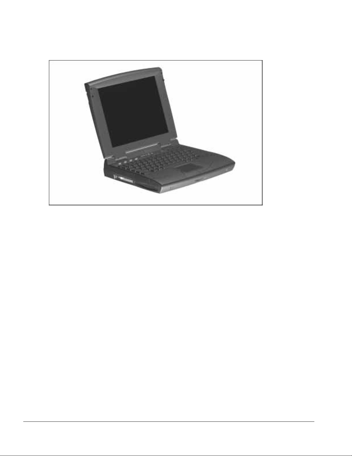
The Compaq Armada 1500 Family of Personal Com pute rs is a line of multimedia
notebook computers with advanced modularity, processors, and video graphics. This
full-funct i on, Pentium-based, family of notebook computers allows full desktop
functionality and connectivity thr ough the use of an optional Convenience Base. The
following computer models are available:
Table 1-1
Compaq Armada Personal Computers
Model
1510 120-MHz 11. 3-inch CSTN 1.0-GB BM51
1510DM 120-MHz 11.3-i nch CSTN 1.0-GB ■■BM52
1520 133-MHz 11. 3-inch CSTN 1.0-GB 256-Kbyte BM53
1520D 133-MHz 11. 3-inch CSTN 1.0-GB 256-Kbyte
1520DM 133-MHz 11.3-i nch CSTN 1.0-GB 256-Kbyte
1550T 133-MHz 12. 1-inch CTFT 1.4-GB 256-Kbyte BM56
1550DMT 133-MHz 12.1-inch CTFT 1.4-GB 256-Kbyte
Pentium
Processor Display Hard Drive
Level 2
Cache CD-ROM Modem
■ BM54
■■BM55
■■BM57
Serial
Configuration
NOTE: All models have 16-MB of standa rd memory, upgradable to 80- MB.
Computer Product Description 1-1
Page 12
. . . . . . . . . . . . . . . . . . . . . . . . . . . . . . . . . . . . .
Figure 1-1. Compaq Armada Personal Computer
1.2 Standard Featur es
The Compaq Armada models have the following sta ndard features :
■ 120- or 133-MHz Pentium processors
■ 16-MB of EDO dynamic ra ndom access memory (DRAM) , expandable to 80 MB
■ 1.4-GB or 1. 0-GB, 2.5- inch with carr ier, or 3-i nch hard drive
■ 11.3-inch Color Super Twist Nematic CSTN, or 12.1-inch Color Thin Film
Transistor (CTFT) SVGA displays
■ Supports Lithi um Ion (Li- ion) and Nickel Metal Hydri de (NiMH) modular batte ry
packs
■ SoundBlaster−compatible audio controller with internal stereo speakers and internal
microphone
■ Full-size 101 key compatible keyboard including 12 f unction keys, 8 cursor control
keys, inverted-T cursor control keys, and embedded numeric keypad
■ Four user-programma bl e keys
■ Touchpad pointing device
■ Operates from an internal battery pack, plus an optional battery pack in the
DualBay, or integrated AC power that is compatible with domestic or international
power sources
■ Power management and security features
1-2 Computer Product Description
Page 13

. . . . . . . . . . . . . . . . . . . . . . . . . . . . . . . . . . . . .
■ Infrared interface for wireless communication with other IrDA-compliant devices at
data rates up to 4 mb/sec
■ Two standard device slots that will accommodate two types I and II and one type III
PC Cards, PCMCIA and CardBus car ds; Compaq Telephony modem in the top slot
and Zoomed-V i deo in the bottom slot
■ 176 pin expansion connector provides the interface to the convenience base options
■ Rear-panel ports provide connec t ions for parallel and serial, external monitor,
keyboard/mouse , and IrDA compliant infrared devices
1.2.1 Software Fulfillment
Replacement software may be ordered directly from Compaq Computer Corporation.
Both the model and the serial numbers of the computer are needed to identify the
specific software available.
Computer Product Description 1-3
Page 14

. . . . . . . . . . . . . . . . . . . . . . . . . . . . . . . . . . . . .
1.3 Options
The compute r supports the fol l owing options:
■ Convenience Base pa ss t hrough model
■ Convenience Base w i th Ethernet
■ Memory expansion boards
■ Li-ion and Ni MH battery packs
■ Automobile Adapter
■ External Battery Charger
■ PCMCIA modem
■ AC power cords for international travelers
■ Hard drive upgrade
■ Internal modem
■ Internal CD-ROM drive
1.3.1 Convenience Base
Compaq Arma da models support the following convenience base models:
■ Convenience base pa ss t hrough
■ Convenience base w i th Ethernet (RJ-45 and BNC connectors); BNC connector not
available in North America
■ Convenience base with Ethernet (BNC connector); not avail able in North America
1.3.2 System Memory Options
The compute r supports optional 8-, 16-, 32-, and 64-MB memory boards. The memory
boards are 60 ns EDO RAM without parity. System memory can be e xpanded to
80-MB of DRA M depending on the model.
1-4 Computer Product Description
Page 15

. . . . . . . . . . . . . . . . . . . . . . . . . . . . . . . . . . . . .
1.3.3 External Battery Charger
The External Battery charger has the following features:
■ Two battery charge slots
■ Accepts both NiMH and Li-ion modular batteries
■ Charges one batte ry in 1.5 hours
■ Charges two batt eries in 3 hours
1.3.4 External Keyboards and
Pointing Devices
Supports Compaq or Compaq compatible PS2 keyboar ds and pointing devices
1.3.5 External Monitors
The Compaq Armada models support all VGA Monitors up to 1024 x 768.
Computer Product Description 1-5
Page 16
. . . . . . . . . . . . . . . . . . . . . . . . . . . . . . . . . . . . .
1.4 External Computer Components
The external computer components are illustrated and described in this section.
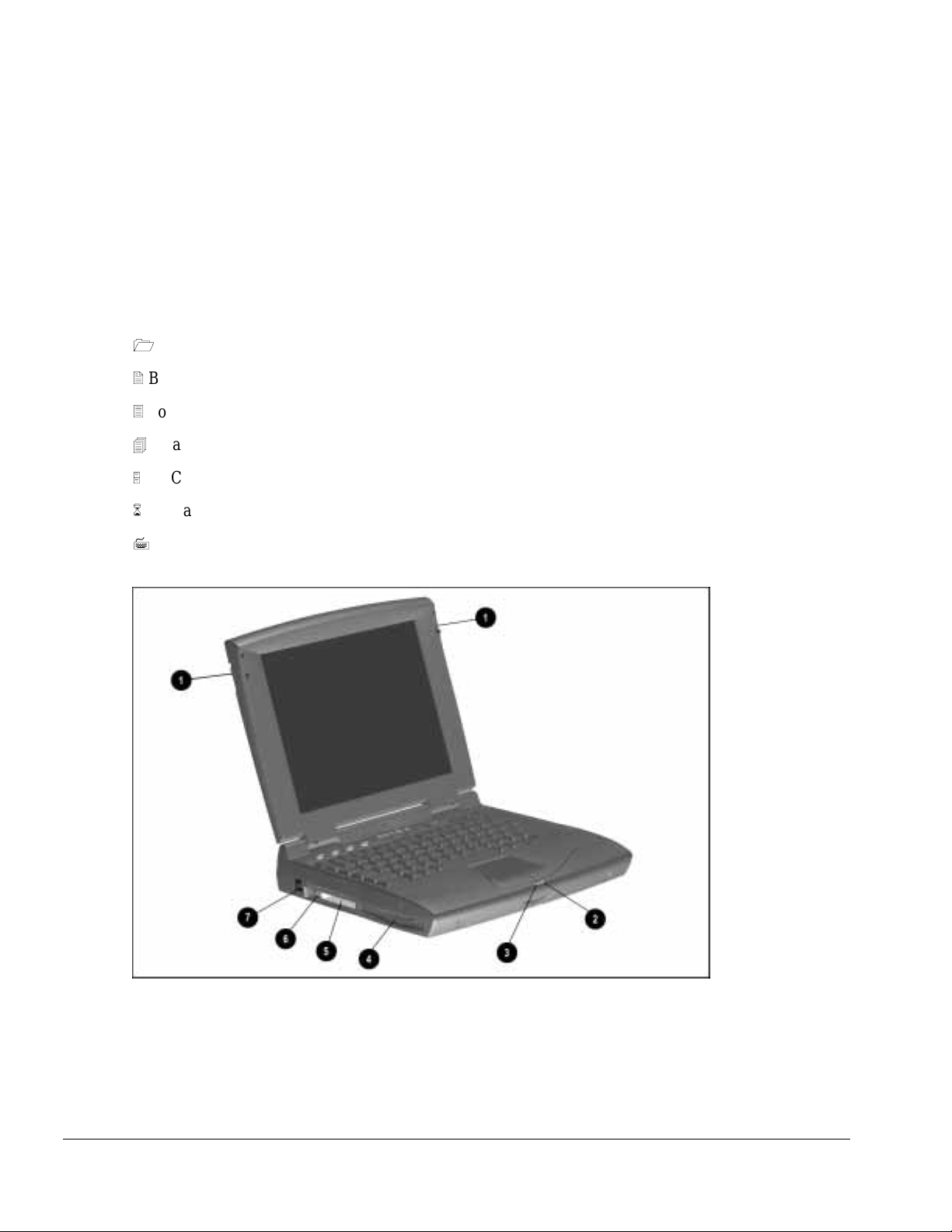
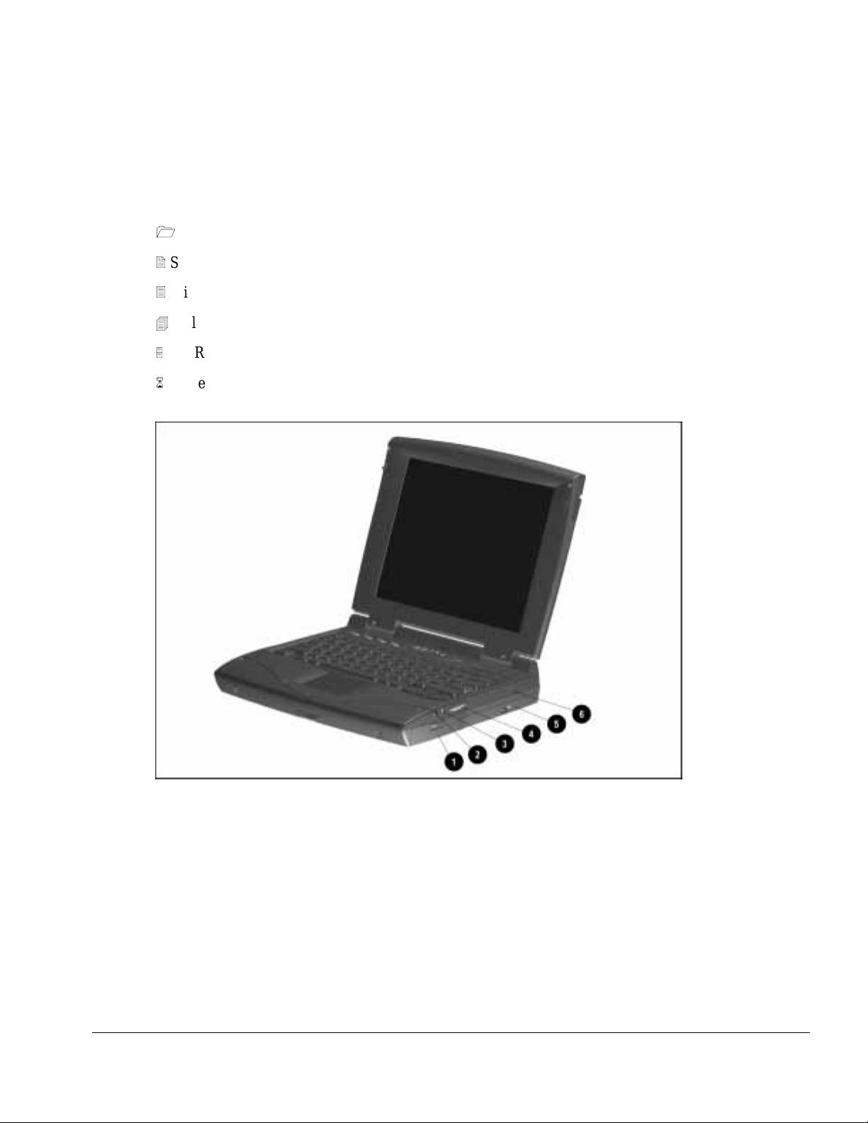
1.4.1 Front and Left Side Components
The front and l eft side exter na l components are shown in the following f igure and
identified in this section:
1
Display latches
2
Battery charge light
3
Power/Suspend light
4
DualBay compartment
5
PC Card slots
6
PC Card eject levers
7
RJ-11 port (on some models)
Figure 1-2. Front and Left Side Components
1-6 Computer Product Description
Page 17
. . . . . . . . . . . . . . . . . . . . . . . . . . . . . . . . . . . . .
1.4.2 Right Side Components
The right side e xternal component s are shown in the fol l owing figure and ide nt i fied in
this section:
1
Battery bay
2
Stereo/spe aker headphone ja ck
3
Microphone jack
4
Volume control buttons
5
CD-ROM drive (on some models )
6
Cable lock provision
Figure 1-3. Right Side Components
Computer Product Description 1-7
Page 18

. . . . . . . . . . . . . . . . . . . . . . . . . . . . . . . . . . . . .
1.4.3 Rear Components
The rear components are shown in the following fi gure and identified in this section:
1
Serial connector
2
Serial number
3
Parallel connector
4
External monitor connect or
5
AC Power connector
6
Docking connector
7
Airflow vents
8
Infrared port
9
Keyboard/Mouse connector
Figure 1-4. Rear Components
1-8 Computer Product Description
Page 19
. . . . . . . . . . . . . . . . . . . . . . . . . . . . . . . . . . . . .
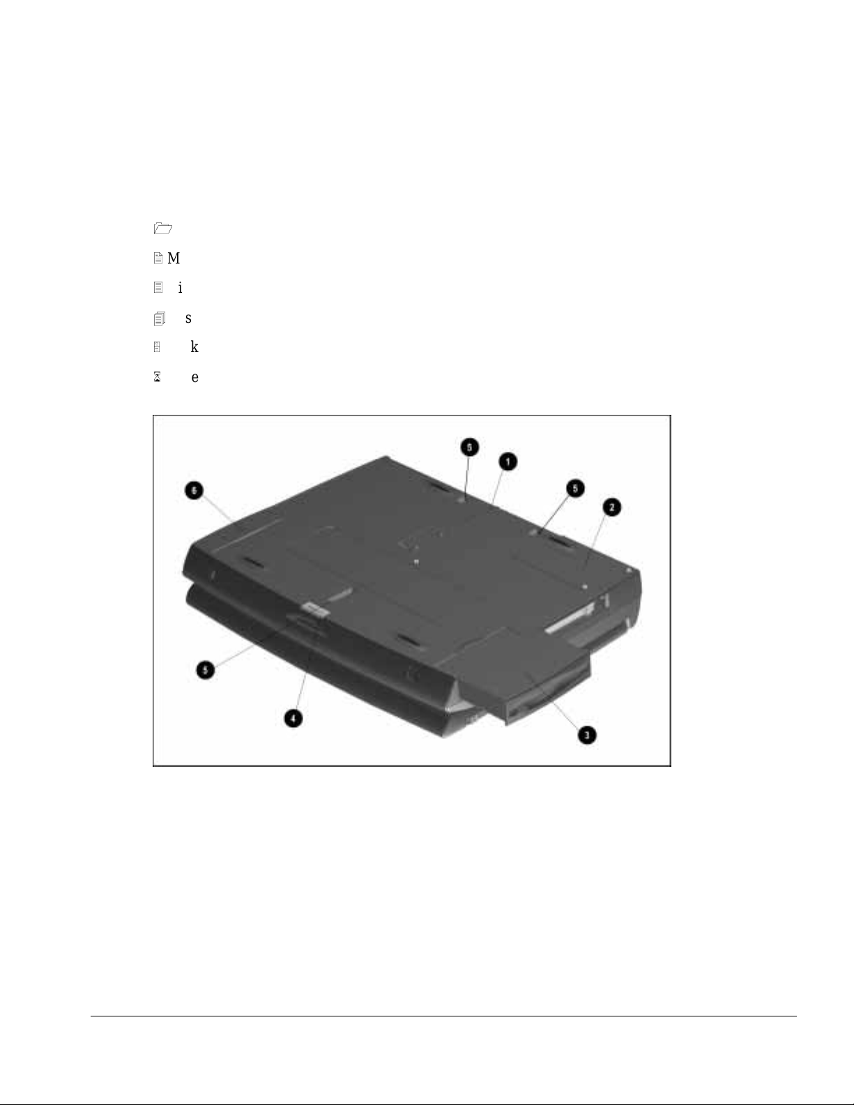
1.4.4 Bottom Components
The bottom external components are shown in the following fi gure and are identified in
this section:
1
Docking alignm ent guide
2
Modem compartment
3
Diskette drive
4
Diskette drive release latch
5
Docking latch receptacles
6
Battery bay traction grip
Figure 1-5. Bottom Components
Computer Product Description 1-9
Page 20

. . . . . . . . . . . . . . . . . . . . . . . . . . . . . . . . . . . . .
1.4.5 Status Panel Lights
The status panel lights are shown in the following figure and are identified in this
section:
1
Hard drive light
2
Diskette drive light
3
Num Lock light
4
Caps Lock light
5
Scroll Lock light
Figure 1-6. Status Panel Lights
1-10 Computer Product Description
Page 21

. . . . . . . . . . . . . . . . . . . . . . . . . . . . . . . . . . . . .
Chapter 2
Convenience Base
Description
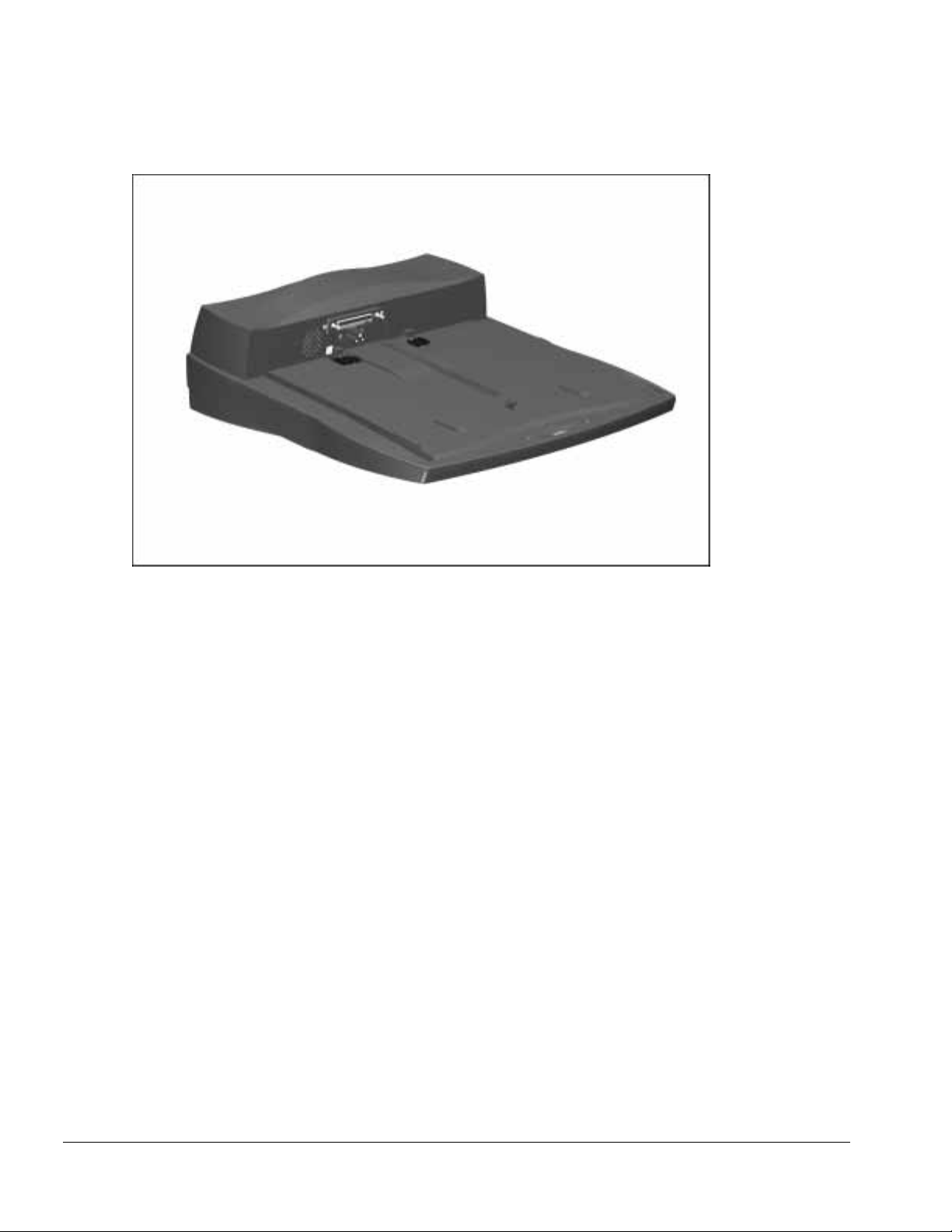
2.1 Models and Features
The convenience bases provide a permanent desktop solution for the computer by
eliminat ing the need to disconne ct external devices such as a printer, keyboard, or
monitor when you undock the computer. All necessary connections and disconnections
are made automatically when the computer is docked and undocked. The f ollowing
convenience models are available:
Table 2-1
Compaq Armada 1500 Family of Convenience Bases
Model Serial Configuration
Convenience Base Pass Through model BNH3
Convenience Base wi th Ethernet BNH1
Convenience Base wi th Ethernet, BNC model BNH3
Convenience Base Description 2-1
Page 22
. . . . . . . . . . . . . . . . . . . . . . . . . . . . . . . . . . . . .
Figure 2-1. Compaq Armada 1500 Convenience Base
2-2 Convenience Base Description
Page 23

. . . . . . . . . . . . . . . . . . . . . . . . . . . . . . . . . . . . .
2.2 Convenience Base Features
The Convenience Ba se pass through model and the convenience base with Ethernet
model include the following features:
Convenience Base
pass through
Convenience Base
with Ethernet
Connections
Speaker/headphone ■■
Audio Line-In ■■
Serial ■■
Parallel ■■
External Monitor ■■
Keyboard ■■
Pointing Device ■■
MIDI/Joystick ■■
Other Features
Cable lock provision ■■
Pass through AC Power ■■
BNC connector (not available in all count ries) ■
RJ-45 connector ■
Options
Monitor Stand ■■
Localized Power Cords ■■
Kensington lock ■■
Optional 100BaseT Ethernet Upgrade ■■
Convenience Base Description 2-3
Page 24

. . . . . . . . . . . . . . . . . . . . . . . . . . . . . . . . . . . . .
2.3 Convenience Base Components
The convenience base components are illustrate d and described in this section.
2.3.1 Front and Right Side Components
The front and right side convenienc e base components are shown and identifi ed in this
section.
1
Power button
2
Security cable lock provision
3
Docking lever
4
Battery charge light
5
Suspend button
6
Power/Suspend light
7
Retaining latch
8
Pass through AC power outlet
9
Docking connector
:
Docking alignm ent pins
;
Docking latches
2-4 Convenience Base Description
Page 25

. . . . . . . . . . . . . . . . . . . . . . . . . . . . . . . . . . . . .
Figure 2-2. Convenience Base Front and Right Side Components
Convenience Base Description 2-5
Page 26

. . . . . . . . . . . . . . . . . . . . . . . . . . . . . . . . . . . . .
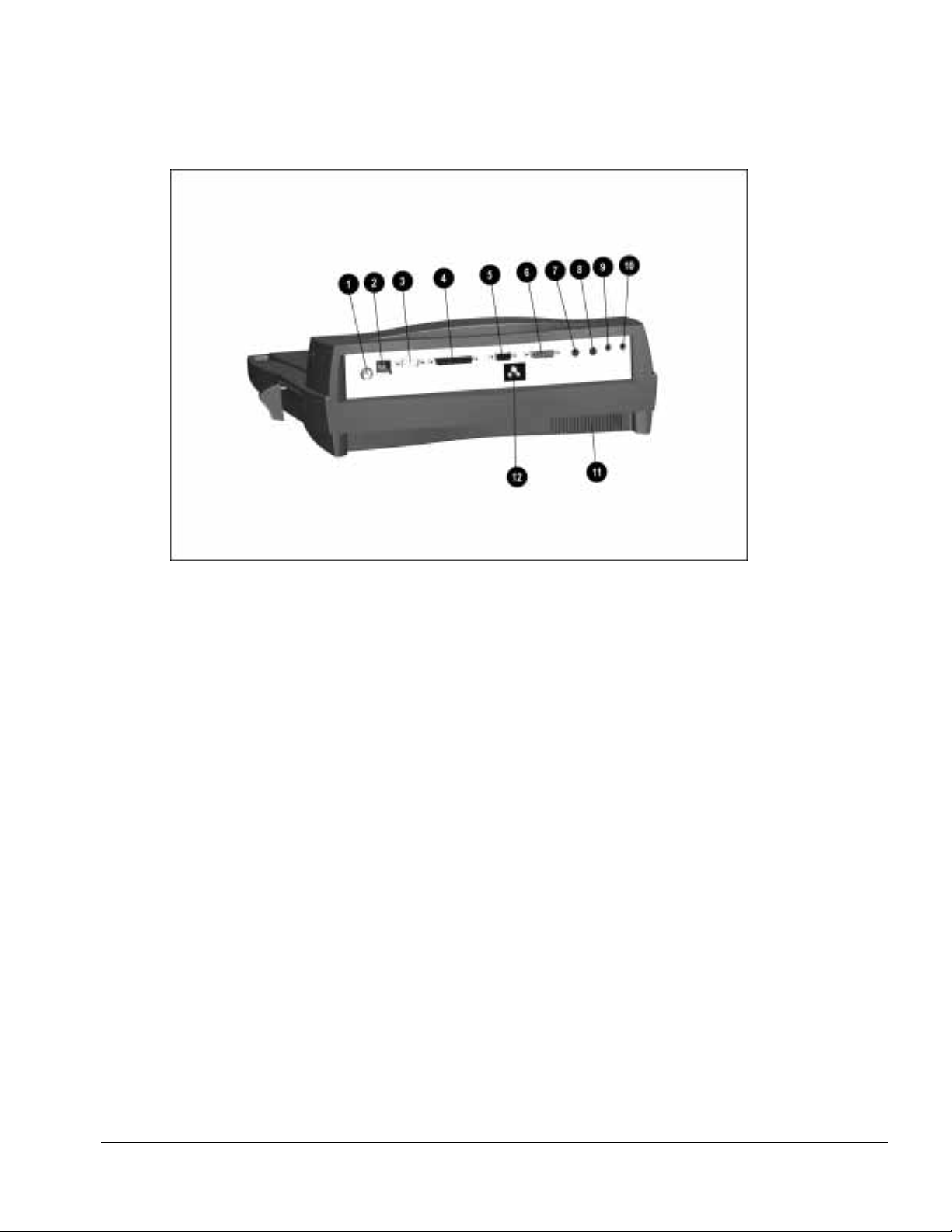
2.3.2 Rear Components
The rear components are shown in the following fi gure and identified in this section:
1
BNC connector ( available on some models)
2
RJ-45 jack
3
Serial connector
4
Parallel connector
5
External monitor connect or
6
MIDI/Joystick connector
7
Pointing device connector
8
Keyboard connector
9
Speaker/he adphone jack
:
Audio Line-i n jack
;
Fan
<
AC power connector
2-6 Convenience Base Description
Page 27
. . . . . . . . . . . . . . . . . . . . . . . . . . . . . . . . . . . . .
Figure 2-3. Convenience Base Rear Components
Convenience Base Description 2-7
Page 28

. . . . . . . . . . . . . . . . . . . . . . . . . . . . . . . . . . . . .
Chapter 3
Troubleshooting
This chapter contains troubleshooting information for the computer and the
convenience base . The basic steps in t roubleshooting the com puter include:
1. Completing the preliminary steps listed in Section 3.1.
2. Running the Powe r-On Self-Test (PO ST) as described in Section 3.3.
3. Running Computer Setup as descr ibed in Section 3. 5
4. Running the Computer Checkup (TEST) as described in Section 3.5.
5. Perfor ming the recom mended actions desc ribed in the diagnostic tables in Section
3.6 if you are unable to exerc i se POST or Com puter Checkup or if the problem
persists after running POST and Computer Checkup.
Follow these guidelines when troubleshooting:
■ Complete the recomme nded actions in the order in which they are given.
■ Repeat POST and Computer Checkup after each recom mended action until the
problem is r esolved and the err or message does not r eturn.
■ Once the probl em is resolve d, do not complete the remaining recommended actions.
■ Refer to Chapter 7 for any removal and replacement procedures that are
recommended for the computer. Refer to Chapter 8 for any removal or replacement
procedures t hat are recommended f or the convenience base.
■ If the problem is inte rmittent, check the computer or convenience base several times
to verify that the problem is solved.
Troubleshooting 3-1
Page 29

. . . . . . . . . . . . . . . . . . . . . . . . . . . . . . . . . . . . .
Use the following table for quick reference to troubl eshooting information:
If You Want To: Run:
Check for POST error messages POST
Check that computer components are recognized and
running properly
View information about the computer and installed or
connected devices
Perform any of the fol l owi ng:
n
Check the system co n figuration
n
Set the system power managem ent
parameters
n
Return the syst em to its original
configuration
n
Check system conf iguration of installed d evices
Computer Checkup (TEST) under Compaq
Utilities
View System Inform ation
(INSPECT)under Compaq Utilities
Computer Setup
3.1 Preliminary Steps
IMPORTANT: Use AC Power whe n running POST, Computer Setup, or Computer
Checkup. A low-battery condition could initiate Suspend or Hiberna tion a nd interrupt
the test.
Before running P OST and Computer Checkup, complete the following steps:
1. Obtain esta blished passwords. I f you must clear the passwords, go to Se ction 3.2.
2. Ensure that the hard drive is installed in the computer.
3. Ensure that the battery pack is installed in the computer and the AC power is
connected to the computer and plugged into an AC power source.
4. Turn on the c omputer.
5. If a powe r-on password has bee n e s t ablished, type the pa ssword and press Enter.
NOTE: The key icon appea rs on the display when the computer is turned on to indicate
that QuickLock/QuickBlank has been initiated. Type the power-on password to
exit QuickLock/QuickBlank. If the password is unknown, it must be cleared (see
Section 3.2).
6. Run Computer Setup (Section 3.5).
7. Use the Hotkeys to adjust the contrast (Fn+F9) and brightness (Fn+F10) to the center
of their ra nges and leave the display open. On models w ith color TFT displ ays,
contrast is not a pplicable.
8. Turn off the computer and all external devices.
9. Disconnect any external devic es that you do not want to test. If you want t o use the
printer to log error messages, leave it connected to the computer.
3-2 Troubleshooting
Page 30

. . . . . . . . . . . . . . . . . . . . . . . . . . . . . . . . . . . . .
NOTE: If a problem only occurs when an external device is connected to the computer,
the problem could be with the external device or its cable . Isolate the problem by
running POST w ith and without the external device connected.
10. Use Advanced Di agnostics and loopback plugs in t he serial and parallel connector s
if you plan to test t he s e ports. You may r un Advanced Diagnostic s from the hard
drive or from a diskette .
If you are r unni ng Diagnostics from the hard drive, complete the following steps:
a. Turn on or restart the computer.
b. Press F10 when the cursor appear s in the upper right corner of the screen. If you
do not press F10 in time, restart the computer and try again. The Welcome screen
appears.
If you are r unning Diagnostics fr om a diskette, c omplete the following steps:
a. Insert the Diagnostics diske t te into the diskette drive and turn on the computer.
b. At the Welcome Screen, press Enter to accept OK.
c. Select Computer Checkup (TEST).
d. Select Prompted Diagnostics after " Identifying System Hardware" completes.
e. Select Interactive Testing and follow the displayed instructions.
Refer to Chapter 4 for the description and spare pa rt number of t he loopback plugs.
After completing the prel i minary steps, run POST (Sec t ion 3.3) and Computer Checkup
(Section 3.5).
3.2 Clearing the Power-On and Setup Passwords
The power-on password prevents use of the computer until the password is entered. The
setup password pre vents unauthorized changes to Computer Se tup. To clear t he
passwords, you must remove all power from the syst em board. If you do not know the
passwords, use the following procedure to clear the password:
1. Remove all battery packs from the batte ry bay and DualBay, i f applicable.
2. Disconnect the AC power.
3. Remove the real time clock battery.
4. Wait five minutes.
5. Reconnect the AC power.
6. Restart the computer. During the Power-On Self Test (POST), a "162 System
Options not Set" message appears. (See Secti on 3.4 for additional POST error
messages).
7. Shut down the computer, t hen turn off the power again.
Troubleshooting 3-3
Page 31

. . . . . . . . . . . . . . . . . . . . . . . . . . . . . . . . . . . . .
8. Replace the real time clock battery.
9. Install the battery pack(s).
10. Proceed with the troubleshooting procedures.
3.3 Power-On Self Test (POST)
The Power-On Self-Test (POST) is a series of tests that run every time the computer is turned on. POST
verifies that the system is configured and functioning properly
To run POST, complete the following steps:
1. Complete the preliminary steps. (Section 2.1).
2. Turn on the computer.
If POST does not detect any errors, the computer beeps once or twice to indicate that
POST has run successfully and boots from the hard drive or from a boot able diskette if
one is installed in the diskette drive.
3.4 POST Error Messages
This section cont ains typical error messages that may occur duri ng the power-on selftest (POST).
If you receive an error message read the description and follow the recommended action
or run Computer Checkup from the Diagnostics diskette . Informat ion about running
Computer Chec kup is presented later in this c hapter.
If POST detects an error, one of the following events occurs:
■ A message wi t h t he prefix "WARNING" appears i nforming you where the error
occurred. T he system pauses until you press F1 t o continue.
■ A message wi t h t he prefix "FAT AL" appears informing you where the error
occurred. After the message, the system emits a series of audible beeps. The system
then stops.
■ The system emits a series of audible beeps. The system then stops.
3-4 Troubleshooting
Page 32

. . . . . . . . . . . . . . . . . . . . . . . . . . . . . . . . . . . . .
Warning messages indicate a potential problem exists such as a system configuration
error. When F1 is pressed, the system shoul d resume. You should be able to correc t
problems that pr oduce WARNING me ssages.
IMPORTANT: When a WARNING message includes the prompt to "RUN SCU," run
Computer Setup. (Computer Setup replaces the SCU utility.)
Fatal errors emit a beep and may display a FATAL message. Fatal errors indicate severe
problems, such as a hardware failure. Fatal errors do not allow the system to resume.
Some of the fatal error beep codes are listed at the end of this section.
Table 3-1
Warning Messages
Message Description
Clock not ticking correctly The real-time clock is not ticking. Repl ace t he real time clock
CMOS checksum invalid, run S CU CMOS RAM information has been corrupted and needs to be
reinitialized by running Computer S etup.
CMOS failure, run SCU CMOS RAM has lost power and needs to be reini t i al i zed by running
Computer Setup.
Floppy controller failed The diskette drive controller failed t o respond t o t he reset comm and.
Power - down the system and check all appropri ate connections. If
the diskette drive controller continues to f ai l, you may need to
replace the system board.
Floppy disk track 0 failed The diskette drive cannot read track 0 of the diskette in the drive.
Try another diskette. If the probl em persist s, you may need t o
replace the diskette drive.
Floppy information invalid, run S CU The drive parameters stored in CMOS RAM do not match the
diskette dri ves d e tected in the system. Run Compu ter Setup.
Hard disk controller error The hard drive controller failed to respond to the reset command.
Check the drive parameters. Power down the system and check all
appropriate connections.
Hardware info does not match video
card, run SCU
Keyboard controller failure The keyboard failed the self-test comm and. Replace the keyboard.
Keyboard failure The keyboard failed to respond to the RESET ID command.
No interrupts from Timer 0 The periodic timer interrupt is not occurring. P ress F1.
RAM parity error at location xxxx A RAM parit y erro r occu rred at the specified (he x) l oca tion.
ROM at xxxx (LENGT H yyyy) with
nonzero checksum (zz)
Time/Date corrupt - run SCU The time and date stored in the real time clock have been corrupted,
Unexpected amount of memory,
run SCU
Hard disk xx failure (or error) A failure or an error occurred when t rying t o access the hard drive.
The video adapter type specified in CMOS RAM does not m at ch t he
installed hardware. Run Computer S et up.
Press F1.
Press F1.
An illegal adapter ROM was located at the specified address. An
external adapter (such as a video card) may be causing the conflict.
Run Computer Setup.
possibly by a power loss. Run Computer Setup.
The amount of memory detected by POS T does not m at ch t he
amount specified in CMOS RA M . Run Computer Setup.
Press F1 and continue.
Troubleshooting 3-5
Page 33

. . . . . . . . . . . . . . . . . . . . . . . . . . . . . . . . . . . . .
Table 3-2
Fatal Error Messages
Message Description Beep Code
CMOS RAM test failed A walking bit test of CMOS RAM location 0E (Hex) -
3F (Hex) failed.
DMA controller fault y A sequential read/write of the transfer count and
transfer address registers within the prim ary and
secondary DMA controllers failed.
Faulty DMA page registers A walking bit read/write of the 16 DMA controller
page registers starting at location 80 Hex fail ed.
Faulty refresh circuits A continuous read/write test of port 61h found that
bit 4 (Refresh Detect) fail ed to toggle within an
allotted amount of t i m e.
Interrupt controller f ai l ed A sequential read/write of vari ous I nterrupt
Controller registers failed.
ROM checksum incorrect A checksum of the ROM BIOS does not match t he
byte value at F000:FFFF.
RAM error at location xxxx RAM error occurred during m emory test. None
Parity error at unknown location Parity error occurred. None
3
4
0
1
5
2
The following table lists some of the Fatal Error beep codes, along with the beep
sequence (short, long, pause) and the meaning of the beeps.
Table 3-3
Fatal Error Beep Codes
Beep Code Beep Sequence Explana tion Remedy
0 S-S-S-P-S-S -L-P The DMA page registers are
faulty.
1 S-S-S-P-S-L-S -P The refresh circuitry is faulty. Replace system board.
2 S-S-S-P-S -L-L -P The ROM checksum is i nco rrect. 1. Flash the RO M .
3 S-S-S-P-L-S-S -P The CMOS RAM test failed. Replace system board.
4 S-S-S-P-L-S-L-P The DMA controller is faul ty. Replace system board.
5 S-S-S-P-L-L-S-P The interrupt controller failed. Replace system board.
6 S-S-S-P-L-L-L-P The keyboard controller failed. Replace system board.
7 S-S-L-P-S-S-S -P Graphics adapter is faulty. Replace system board.
8 S-S-L-P-S-S-L-P Internal RAM is fault y. Replace processor board.
S = Short, L = Long, P = Pause
Replace system board.
2. Replace system board.
3-6 Troubleshooting
Page 34

. . . . . . . . . . . . . . . . . . . . . . . . . . . . . . . . . . . . .
3.5 Compaq Utilities
Run the Compaq Utilities to view or test system information and installe d or connected devices. Run
Compaq Utilities from either the computer hard drive or from diskette.
If running Compaq Utilities fr om a diskette, note the following:
n
Use version 10.13c or later .
n
You will not be able to make a utilities diskette.
n
Use the Comput er Setup diskett e to run Computer Setup.
The Utilities menu includes the following:
n
Computer Setup
n
Computer Checkup (TEST)
n
View System Information (INSPECT)
n
Create Dia gnostics diskette (ha rd drive only)
n
Manage Diagnostics Partition (diskette only)
If the proble m persists, c all for support. F ollow these steps to pr epare for the support call:
1. Run Computer Checkup and save the device list to a fil e and print or save t he log of errors.
2. Run the View System Information (INSPECT) utility and print or save that information.
3. Have the files or the printed information available when call ing for support.
Running Computer Setup
Computer Setup contains a group of utilities that give you an overall pict ure of the
computer’s hardw a re configuration and aid in tr oubleshooting. Use these utilities to set
custom feat ures, such as security options, power conservation levels, and startup
preferences.
A computer running Windows 95 automatically recogniz es and configures t he system
for new devices. However, if there is a configuration problem , or you want to vie w or
reset configuration settings, use Computer Setup.
Computer Se tup provides two methods to view the computer’s configuration - by type
or connection. The default method for vie wing Computer Setup is by type.
Troubleshooting 3-7
Page 35

. . . . . . . . . . . . . . . . . . . . . . . . . . . . . . . . . . . . .
Categories by type i nclude:
n
System Fea tures—security, power, boot managem ent
n
Communicat ion—ports, modem, other c ommunication devices
n
Storage—st orage-rel ated devices suc h as hard drive or diskette
n
Input Device s —keyboard, mouse, and other input devices
n
Network—N etwork adapte r, or other ne twork-rel ated devices ( Available only w hen
docked or when PC Card is installed
n
Audio—sound properties and audio de vice settings
n
Video—monit or video device resources
n
Other devices—devices that could not be categorized
Categories by conne ction include:
n
System Fea tures—security, power, boot managem ent
n
System Devic es—keyboard, mouse, parallel and serial ports
n
ISA—ISA bus and related devices
n
PCI—PCI bus a nd connected devices
n
PC Card (PCMCIA) —PC Ca rd bus and PC Card devices
Running Computer Checkup (TEST)
Computer Checkup (TEST) det ermines whet her the various computer component s and
devices are recognized by t he system and ar e functioning prope rly. You can displ ay,
print, or sa ve the inform ation generated by Computer Chec kup.
Computer Chec kup is installed on the hard drive. If the hard drive is nonfunctiona l, you
can run it from a diskette.
NOTE: It is recommended that you make diskette copies of Compute r Checkup and
keep them available for future needs. A current copy can be obtained from the Compaq
Customer Support Center.
3-8 Troubleshooting
Page 36

. . . . . . . . . . . . . . . . . . . . . . . . . . . . . . . . . . . . .
Computer Checkup
To run Computer Checkup from the ha rd drive, compl ete the followi ng st eps:
1. Close all applications and shut down the computer.
2. Turn off the computer.
3. Turn on the computer.
4. When the cursor moves to the ri ght side of the scre en, press F10.
A Welcome Screen is displayed that is followed by the Compaq Utilities main menu.
5. From the Compaq Utilities main menu, sele c t Computer Checkup (TES T).
A diagnostics menu is displayed.
6. Select the option to view the device list.
A list of the installed hardware devices is displayed.
NOTE: Computer Checkup does not detect all non-Compaq devices.
7. Verify that Computer Che ckup correctly de tected the instal led devices.
If the list i s correct, se l ect OK. The Computer Checkup option menu is displayed
again.
If the list is incorrect, verify that the new devices are installed properly.
8. Select one of the followi ng from the diagnosti cs menu:
■ Quick Check Diagnost ics. Runs a quick, general test on each device with a
minimal number of prompts. If err ors occur, they display when the testing i s
complete. You cannot print or sa ve the error messages.
■ Automatic Diagnostics. Runs an unattended, maximum testing of each device
with minim al prompts. You c an choose how many times to run the tests, to stop
on errors, or to print or sa ve a log of err ors.
■ Prompted Diagnostics. Allows maximum control over te sting the devices. You
can choose attended or unattende d t esting, decide to stop on errors, or choose to
print or save a l og of errors.
9. Follow the instructions on the screen as the devices are tested. When testing is
complete, the D iagnostics menu appea rs.
10. Exit the Diagnost ics menu.
NOTE: Exiting the Compaq Utilities menu restarts the computer and saves the
changes.
Troubleshooting 3-9
Page 37

. . . . . . . . . . . . . . . . . . . . . . . . . . . . . . . . . . . . .
11. Look up the Compute r Checkup error codes that were displayed by re ferring to
"Computer Che ckup (TEST) Error Codes" and take the re commended ac tion.
12. Rerun POST and Computer Checkup, taking the re commended actions in given
order until the problem is solved and no error messages occur.
Computer Checkup (TES T) Error Codes
IMPORTANT: Rerun Computer Checkup each time you complete a recommended action
step. If the problem is resol ved when POST and Com puter Checkup are rerun (i.e., with
no error codes) do not perform the remaini ng recommende d action steps.
Computer Checkup (TEST) error codes occur if the system recognizes a problem while
running Computer Checkup. These error codes help identify possible defe ctive
assemblies. Tables 3-4 through 3- 14 list Computer Checkup error codes, a description
of the error condition, and the recommended action for resolving the condition. For
removal and replacement procedures for the computer, refer to Chapter 7. For removal
and replacement procedures for the convenience base, refer to Chapter 8.
NOTE: The error codes in the following tables are listed in an AYE-XX format, where:
A or AA = Number that represents the faulty assembly.
Y = Test or action that failed.
XX = Specific problem.
View System Information (INSPECT)
The View System I nformation (INSPECT) utility provides information a bout the
computer and i nst alled or connected devices. You ca n display, print, or save the
information.
Follow these steps to run INSPECT from the hard drive:
1. Turn on the external devi ces that you want to test. Connect t he printer if you want to
print the information.
2. Turn on or restart the computer.
3. Press F10 when the prompt appears in the right side of the display. The Compaq
Utilities screen appears.
4. Select View System Information (INSPECT) from the Dia gnost ics menu.
5. Select the item you w ant to view from the follow ing list:
System Memory
ROM Audio
Keyboard Operating system
System ports System files
System storage Windows files
Graphics Miscellaneous
6. Follow the instructions on the screen to c yc l e through the screens, to return to the list
and choose another item, or to print the information.
3-10 Troubleshooting
Page 38

. . . . . . . . . . . . . . . . . . . . . . . . . . . . . . . . . . . . .
3.6 Diagnostic Error Codes
Diagnostic er ror codes occur if the system re cognizes a problem while running the
Compaq Diagnostic program. These error codes help identify possibly de fective
subassemblies.
Tables 3-4 through 3-14 list possible error codes, a description of the er ror condition,
and the action required to resolve the err or condition.
IMPORTANT: Retest the system after completing each step. If the problem has been
resolved, do not proceed with the remaining steps.
For assistance in the removal and replacement of a particular subassembly, see
Chapter 7, "Removal and Replacement Procedures." For removal and replacement
procedures f or the convenience base, see Chapter 8.
Table 3-4
Processor Test Err or Codes
Error
Code Description Recommended Action
101-xx CPU test failed Replace the processor board and retest.
103-xx Coprocessor or Weitek Error
103-xx DMA page registers test failed Replace the system board and retest.
104-xx Interrupt controller ma st er t est failed
105-xx Port 61 error
106-xx Keyboard controller self-test failed
107-xx CMOS RAM test failed
108-xx CMOS interrupt test failed
109-xx CMOS clock test failed
110-xx Programmable timer load data test failed
113-xx Protected mode test fail ed
114-01 Speaker test failed
1. Check system co n figuration .
2. Verify cable connections to speaker.
3. Replace the system board and rete st .
Troubleshooting 3-11
Page 39

. . . . . . . . . . . . . . . . . . . . . . . . . . . . . . . . . . . . .
Table 3-5
Memory Test Error Codes
Error
Code Description Recommended Action
200-xx Memory machine ID test fai l ed The following steps apply to error codes 200-xx and
203-xx:
203-xx Memory system ROM checksum failed
203-xx Write/Read test fai l ed The following steps apply to error codes 203-xx
204-xx Address test failed 1.Remove the memory board and retest.
211-xx Random pattern test fai l ed 2 Install a new memory board and retest.
214-xx Noise test failed
215-xx Random address test failed
Keyboard Test Error Codes
Error
Code Description Recommended Action
300-xx Failed ID Test The following steps apply to error codes 300-xx
301-xx Failed Selftest/Interface Test 1.Check the keyboard connection. If disconnected,
303-xx Failed Individual Key Test 2. Replace the keyboard and retest.
304-xx Failed Keyboard Repeat Test 3. Replace the system board and retest.
1.Flash the system ROM and retest.
2.Replace the system board and retest.
through 215-xx:
Table 3-6
through 304-xx :
turn off the computer and connect the keyboard.
Table 3-7
Parallel Printer Test Error Codes
Error
Code Description Recommended Action
401-xx Printer failed or not connected The following steps apply to error codes 401-xx
through 403-xx :
402-xx Failed Port Test 1. Connect the printer.
403-xx Printer pattern te st f ai l ed 2. Check power to the printer.
3. Install the loop-back connector and retest.
4. Check port and IRQ configuration.
5. Replace the system board and retest.
3-12 Troubleshooting
Page 40

. . . . . . . . . . . . . . . . . . . . . . . . . . . . . . . . . . . . .
Table 3-8
Diskette Drive Test
Error
Code Description Recommended Action
600-xx Diskette ID drive types test
failed
601-xx Diskette format f ai le d 1.Replace the diskette media and retest.
602-xx Diskette read test fail ed 2.Check and/or replace the diskette power and signal
603-xx Diskette write, read, com pare t e st f ai l ed 3.Replace the diskette drive and retest.
604-xx Diskette random read test failed 4.Replace the system board and retest.
605-xx Diskette ID media fail ed
606-xx Diskette speed test failed
609-xx Diskette reset controlle r t est failed
610-xx Diskette change line test fai l ed
697-xx Diskette type error
698-xx Diskette drive speed not within li m i ts
699-xx Diskette drive/media ID error Run Computer Set up.
Serial Test Error Codes
Error
Code Description Recommended Action
1101-xx Serial port test failed
Hard Drive Test Error Codes
Error
Code Description Recommended Action
1701-xx Hard drive format test failed The following steps apply to error codes 1701-xx
1702-xx Hard drive read test failed 1.Run Computer Setup.
1703-xx Hard drive write/read/compare test
failed
1704-xx Hard drive random seek test failed 3.Replace the system board and retest.
1705-xx Hard drive controller test failed
1706-xx Hard drive ready test failed
1707-xx Hard drive recalibration test failed
1708-xx Hard drive format bad track test failed
1709-xx Hard drive reset controller test failed
1710-xx Hard drive park head test failed
1715-xx Hard drive head select test failed
1716-xx Hard drive conditional format test f ai l ed
1717-xx Hard drive ECC* test failed
1719-xx Hard drive power mode test failed
1724-xx Network preparation test failed
1736-xx Drive monitoring test failed
* ECC = Error Correction Code
The following steps apply to error codes 600-xx
through 698-xx:
cables and retest.
Table 3-9
1.Check port configuration.
2.Replace the system board and retest.
Table 3-10
through 1736-xx :
2.Replace the hard drive and retest.
Troubleshooting 3-13
Page 41

. . . . . . . . . . . . . . . . . . . . . . . . . . . . . . . . . . . . .
Table 3-11
Video Test Error Codes
Error
Code Description Recommended Action
501-xx Vi deo cont rol l er t est failed
502-xx Vi deo m em ory t est failed
503-xx Video attribute test failed
504-xx Vi deo character set test failed
505-xx Vi deo 80 × 25 m ode 9 × 14 character
cell test failed
506-xx Video 80 × 25 m ode 8 × 8 character
cell test failed
507-xx Video 40 × 25 m ode test failed
508-xx Video 320 × 200 m ode color set 0 t est
failed
509-xx Video 320 × 200 m ode color set 1 t est
failed
510-xx Video 640 × 200 m ode test failed
511-xx Video screen memory page t est f ai l ed
513-xx Vi deo gray scale t est f a il ed
514-xx Video whi te screen test failed
516-xx Video noi se pat t ern test failed
2403-xx Video memory test failed
2403-xx Video attribute test failed
2404-xx Video character set test failed
2405-xx Video 80 × 25 mode 9 × 14 character
cell test failed
2406-xx Video 80 × 25 mode 8 × 8 character
cell test failed
2408-xx
2409-xx Video 320 × 200 mode color set 1 test
failed
2410-xx Video 640 × 200 mode test failed
2411-xx Video screen memory page test failed
2413-xx Video gray scale test failed
2414-xx Video white screen test failed
2416-xx Video noise pattern test failed
2418-xx ECG/VGC memory test fail ed
The following apply to error codes 501-xx through
516-xx:
1. Connect and external monitor and ret est .
2. Replace the LED status board and retest .
3. Replace the display and retest.
4. Replace the system board and rete st .
The following steps apply to error codes 2403-xx
through 2456-xx:
1. Run Computer Setup.
2.Disconnect external monitor and test with
internal LCD display.
3.Replace the display assembly and retest.
4. Replace the system board and rete st .
3-14 Troubleshooting
Page 42

. . . . . . . . . . . . . . . . . . . . . . . . . . . . . . . . . . . . .
Table 3-11 Continued
Error
Code Description Recommended Action
2419-xx ECG/VGC ROM checksum test failed The following steps apply to error codes 2403-xx
through 2456-xx:
2421-xx ECG/VGC 640 × 200 graphics mode test
failed
2423-xx ECG/VGC 640 × 350 16 color set test fail ed 2. Disconnect external monitor and te st with internal
2423-xx ECG/VGC 640 × 350 64 color set test failed 3. Replace the display assembly and retest.
2424-xx ECG/VGC monochrome text mode test
failed
2425-xx ECG/VGC monochrome graphics mode
test failed
2431-xx 640 × 480 graphics test failure
2433-xx 320 × 200 graphics (256 color mode) test
failure
2448-xx Advanced VGA Controller test fai l ed
2451-xx 133-column Advanced VGA test failed
2456-xx Advanced VGA 256 Color
test failed
2458-xx Advanced VGA BitBLT test The following applies to error codes 2458-xx through
2468-xx Advanced VGA DAC test Replace the system board and retest.
2477-xx Advanced VGA data path test
2478-xx Advanced VGA BitBLT test
2480-xx Advanced VGA Linedraw test
1. Run Computer Setup.
LCD display.
4. Replace the system board and rete st .
2480-xx:
Table 3-12
Audio Test Error Codes
Error
Code Description Recommended Action
3206-xx Audio System Internal Error Replace the audio board and retest.
Troubleshooting 3-15
Page 43

. . . . . . . . . . . . . . . . . . . . . . . . . . . . . . . . . . . . .
Table 3-13
Pointing Device Interface Test Error Codes
Error
Code Description Recommended Action
8601-xx Mouse test failed The following steps apply to 8601-xx and 8603-xx:
1. Replace the top cover assembly.
8603-xx Interface test fa il e d 2. Replace the system board and retest.
Table 3-14
CD-ROM Test Error Codes
Error
Code Description Recommended Action
3301-xx CD-ROM drive read test failed The fo ll owi ng st eps appl y t o error codes 3301-xx through
3305-xx and 6600-xx through 6623-xx:
3305-xx CD-ROM drive seek test failed 1. Replace the CD and retest.
6600-xx ID test failed 2. Replace the CD-ROM drive and retest.
6605-xx Read test failed 3. Replace the system board and ret est .
6608-xx Controller test failed
6623-xx Random read test failed
3-16 Troubleshooting
Page 44

. . . . . . . . . . . . . . . . . . . . . . . . . . . . . . . . . . . . .
3.7 Troubleshooting Without Diagnostics
This section provides information about how to identify and correct some common
hardware, memory, a nd software probl ems. It also e xpl ains several types of common
messages that may be displayed on the screen. The following pages contai n
troubleshooting i nformation on:
■ Audio ■ Pointing device
■ Battery/Battery gauge ■ Memory
■ Diskette/Diskette drive ■ PC Card
■ Hard drive ■ Power
■ CD-ROM drive ■ Printer
■ Hardware installation ■ Screen (LCD and CRT)
■ Infrared connection ■ Software
■ Keyboard (N umeric keypad)
3.7.1 Solving Minor Problems
Some minor problems and possible solutions are outlined in the following tables. If the
problem appe ars related to a softwar e application, check the documentation provided
with the software.
Solving Audio Problems
Some common audio problems and sol utions are listed i n the following table.
Table 3-15
Solving Audio Problems
Problem Probable Cause Solution(s)
Computer beeps once after
you turn it on.
Computer does not beep after
the Power-On Self-Test
(POST).
This is typical; it indicates
successful completion of the
Power-On Self-Test (P OS T ).
Speaker volume is off or has
been turned down.
Beeps have been turned off.
No action is required.
If the speaker icon is not displayed on the
display, pre ss Fn+F5 to adjust the volume.
Run Computer Setup and turn on beeps.
Troubleshooting 3-17
Page 45

. . . . . . . . . . . . . . . . . . . . . . . . . . . . . . . . . . . . .
Solving Battery and Battery Gauge Problems
Some common causes and solutions for battery problems are listed in the following
table. The " S olving Power Problems" section in thi s chapter also may be applicable.
Table 3-16
Solving Battery and Battery Gauge Problems
Problem Probable Cause Solution(s)
Computer won’t tu rn on when
battery pack is inserted and
power cord is unplugged.
Computer is beeping
and battery light is blinking.
Computer battery light bl i nks
to indicate low- battery
condition, but computer does
not beep.
Battery light doesn’t light and
battery pack won’t fast charge.
Computer turned off and
information in mem ory was
lost when replacing the
battery pack.
Battery is discharged. Connect the computer to an exte rnal power
source and charge the battery pack.
Replace the battery pack with a full y charged
battery pack.
Check the battery connectors on the system
board to verify they are evenly spaced and
that they are not bent or broken.
Battery charge is low. Immediately save any open file(s). Then do
any one of the following:
■ Connect the computer to an external power
source to charge the battery pack.
■ Initiate Suspend and replace the battery
pack with a fully charged battery pack.
■ Turn the computer off or initiat e Hibernation
until you can find another power source or
charge the battery pack.
Low - battery beeps were
turned off.
Volume is turned off or turned
down too low.
Battery pack is already
charged.
Battery pack was exposed to
temperature extremes.
Battery pack is at end of its l ife. Replace battery pack.
The battery pack was not
replaced.
Run Computer Setup to tu rn on t he l ow battery warning beeps.
Press Fn+F5 to turn the speaker on and then
adjust the volume.
No action is necessary.
Allow time for the battery pack to return to
room temperature.
Turn off the computer and restart.
Continued
3-18 Troubleshooting
Page 46

. . . . . . . . . . . . . . . . . . . . . . . . . . . . . . . . . . . . .
Table 3-16 Continued
Problem Probable Cause Solution(s)
Battery charge does not last
as long as expected.
Battery pack is warm to the
touch after charging.
Battery gauge is inaccurate. The battery pack is new or has
Battery pack operating time
is far less than the
documented average
operating time.
Battery is being exposed to
high temperatures or
extremely cold temperatures.
Battery has partially selfdischarged.
Power management is
disabled.
An external device or PC Card
is draining the battery.
Normal warming has occurred
due to charging.
not been used for a long
period.
Power management is turned
off or disabled.
An external device or PC Card
is draining the battery.
Battery pack has partially
self-discharged.
Fuel gauge is inaccurate. Use the low battery warning beeps to
Battery pack is being drained
by high power-use accessory.
Battery pack is being exposed
to high temperatures or
extremely cold temperatures.
Keep the battery pack within t he
recommended temperature ranges.
Operating: 50°F to 104°F(10°C to 40°C)
Storage: -4°F to 86°F (-20°C to 30°C )
Recharge the battery pack.
Recharge the battery. Discharge the batt ery
completely and then recharge it.
Set a power management level in Comput er
Setup.
Turn off or disconnect external devices when
not using them.
No action is required.
Fully charge the battery pack until the batt ery
light on the computer turns off .
Condition the battery pack by fully charging,
then fully discharging, and then full y
recharging. If condition persists, replace t he
battery. If the battery gauge is still inaccurate,
replace the system board.
Enable power management in Computer
Setup and in Windows Power Properti es. The
power management icon should be visible on
the status panel.
Turn off or disconnect external devices when
not using them.
To maintain the charge, leave battery packs
in the computer when it is connected to
external power.
If the computer is disconnected from external
power for more than two weeks, remove
battery packs from the com put er to reduce
the discharge rate.
determine the low batt ery condit i on.
Reduce use of accessories which drain
power such as the CD-ROM drive or PC
Card.
Keep the battery pack within t he
recommended temperature ranges:
Operating: 50°F to 104°F(10°C to 40°C)
Storage: -4°F to 86°F (-20°C to 30°C ).
Recharge the battery pack.
Troubleshooting 3-19
Page 47

. . . . . . . . . . . . . . . . . . . . . . . . . . . . . . . . . . . . .
Solving Diskette an d Diskette Drive Problems
Some common causes and solutions for diskette and diskett e drive problem s are listed
in the following table.
Table 3-17
Solving Diskette and Diskette Drive Problems
Problem Probable Cause Solution(s)
Diskette drive light does not
turn on.
Diskette drive light stays on. Diskette is damaged. Run SCANDISK on the di skette. At the
Diskette drive cannot write to a
diskette.
Diskette drive cannot read a
diskette.
Cannot boot from diskette. Boot abl e di skett e i s not i n
Diskette drive is not installed
properly.
Diskette is incorrectly insert ed. Remove diskette and reinsert.
Software program is damaged. Check the program diskettes.
Diskette is write-protected. Disable the diskette’s write-protect feature or
Computer is writing to
the wrong drive.
Not enough space is left on the
diskette.
Drive error has occurred. Run Computer Checkup from the Compaq
Diskette is no t formatte d. Format the disket te. At th e system prompt,
The wrong type of diskette is
being used.
Diskette has a bad sector. Copy files to hard drive or another di sket t e .
Drive error has occurred. Run Computer Checkup from the Compaq
Diskette is not
formatted.
drive A.
Diskette Boot is disabled in
Computer Setup.
Remove the diskette drive and install it
properly.
system prompt, enter
SCANDISK A:
use a diskette that is not write-prot ect ed.
Check the drive letter in the path stat em ent .
Use another diskette.
Diagnostics diskette.
enter
FORMAT A:
Use the type of diskette required by the dri ve.
Reformat bad floppy.
Diagnostics diskette.
Format the diskette. A t the system prompt,
enter
FORMAT A:
Put the bootable diskette i n dri ve A. If a
diskette drive is in the computer DualBay, that
is drive A.
Run Computer Setup and enable Diskett e
Boot from the Boot M anagem ent menu.
3-20 Troubleshooting
Page 48

. . . . . . . . . . . . . . . . . . . . . . . . . . . . . . . . . . . . .
Solving Hard Drive Problems
Some common causes and solutions for hard drive problems are listed in the following
table.
Table 3-18
Solving Hard Drive Problems
Problem Probable Cause Solution(s)
Reading hard drive takes an
unusually long time after
restarting the computer.
Hard drive error occurs. Hard drive has bad sectors or
Hard drive does not work. Hard drive is not seat ed
Solving CD-ROM Dri ve P r ob l ems
Some common causes and solutions for CD-ROM drive problems are l isted in the
following table.
System entered Hibernation
due to low-battery condition
and is now exiting from it.
has failed.
properly.
Hard drive is damaged. Replace t he hard dri ve.
Give the system time to restore the
previously saved data to its exact state
before Hibernation.
Run Computer Checkup.
See POST error messages.
Turn off the computer, rem ove and reinsert
the hard drive, then turn the computer on.
Table 3-19
Solving CD-ROM Drive Pr oblems
Problem Probable Cause Solution(s)
CD-ROM drive cannot read a
compact disc.
CD-ROM drive does not
work.
Compact disc is upside down
or is improperly inserted in the
CD-ROM drive.
CD-ROM drive is not seated
properly.
CD-ROM drive was inserted
while the computer was on, in
Suspend, or in Hibernation.
Open the CD loading tray, lay the compact
disc in it (label side up), then close the tray.
Shut down the computer, remove and
reinsert the drive, then turn on the computer.
Shut down computer; then turn i t on agai n.
The drive is initialized during power up.
Troubleshooting 3-21
Page 49

. . . . . . . . . . . . . . . . . . . . . . . . . . . . . . . . . . . . .
Solving Hardware Installation Problems
Some common causes and solutions for hardware installation problems are listed in the
following table.
Table 3-20
Solving Hardware Installation Problems
Problem Probable Cause Solutions(s)
A new device is not
recognized as part of
the comput e r system.
Solving Infrared Connection Problems
Some common causes and solutions for infrared c onnection problems a re listed in the
following table.
Cable(s) of new external
device are loose or
power cables are unplugged.
Power switch of new external
device is not turned on.
Device is not seated properly. T urn off the computer and reinsert the devi ce.
Ensure that all cables are properly and
securely connected.
Turn off the computer, turn on the external
device, then turn on the computer to integrate
the device with the computer system.
Table 3-21
Solving Infrared Connection Problems
Problem Cause Solution(s)
Cannot link with another
computer.
Data transmission problem. Direct sunlight, fluorescent
Interrupt request (IRQ) confl i ct . Check IRQ assignments for conflicts and
reassign as necessary.
Baud rate conflict. Select the same baud rate fo r bot h
computers.
Remove the interfering light sources.
light, or flashing incandescent
light is close to the infrared
connections.
Interference from other wi rele ss
devices.
Physical obstruction. Do not place objects between the two units
Movement. Do not move either unit during data
Orientation. Adjust devices so that they point within
Distance. Verify that devices are not more t han
Keep remote control units such as wireless
headphones and other audio devices away
from the infrared connections
that will interfere with a line-of-sight data
transmission.
transmission.
30 degrees of each other.
3 feet (1 m) apart.
3-22 Troubleshooting
Page 50

. . . . . . . . . . . . . . . . . . . . . . . . . . . . . . . . . . . . .
Solving Keyboard/Numeric Keypad Problems
Some common causes and solutions for keyboard/numer ic keypad problem s are listed
in the following table.
Table 3-22
Solving Keyboard/Numeric Keypad Problems
Problem Probable Cause Solution(s)
Embedded numeric keypad on
computer keyboard is
disabled.
Keyboard is locked. QuickLock initiated. Enter the password to exit QuickLock.
Solving Pointing Device Problems
Some common causes and solutions for pointing device probl ems are listed in the
following table.
Problem Cause Solution(s)
External pointing device does
not work.
Integrated pointing device
does not work.
Num Lock function is not
enabled.
Press the Fn+NumLk keys to enable the
Num Lock function and embedded numeric
keypad. The Num Lock icon on the status
panel turns on.
Table 3-23
Solving Pointing Devi ce Problems
Incorrect device driver or no
device driver is installed.
The device driver is not
installed in Windows.
An external pointing device
is connected and the system
has disabled the internal
pointing device.
Install the device driver.
Install the device driver in Windows.
Initiate Suspend and disconnect the external
pointing device.
Troubleshooting 3-23
Page 51

. . . . . . . . . . . . . . . . . . . . . . . . . . . . . . . . . . . . .
Solving Memory Problems
Some common causes and solutions for memory problems are listed in the following
table.
Table 3-24
Solving Memory Problems
Problem Probable Cause Solution(s)
Memory count during PowerOn Self-Test (POS T) i s
incorrect.
"Out of Memory" message is
displayed on the screen or
insuffici en t memory
error occurs during operation.
Optional memory expansion
board is installed incorrectly,
is incompatible with
the computer, or is defective.
System ran out of memory f or
the application.
Too many TSR (terminate and
stay resident) applications are
running.
Ensure that the optional mem ory expansion
board is installed correctly.
Check the application documentation for
memory requirements.
Install additional m em ory.
Remove from memory any TSR applications
that you do not need.
3-24 Troubleshooting
Page 52

. . . . . . . . . . . . . . . . . . . . . . . . . . . . . . . . . . . . .
Solving PC Card Problems
Some common causes and solutions for PC Card problems are listed in the following
table.
Table 3-25
Solving PC Card Problems
Problem Probable Cause Solution(s)
PC Card error messages
appear when the computer is
turned on.
Computer does not beep
when PC Card is inserted
butt PC Card works corre ctly
When turned on, the
computer does not beep
when a PC Card is inserted.
The PC Card drivers (Socket
Services, Card Services,
Card ID) fail with error
messages when the
computer is turned on.
PC Card modem, fax, or
network card does not work.
The PC Card slot is disabled. Run Computer Setup and enable the PC
Card slots on the Security Menu.
System beeps are turned
down.
Card is not inserted properly
PC Card beeps are disabled.
Speaker is turned off or
volume is turned down.
PC Card drivers are not
installed.
The PC Card slots are
disabled.
Card or card driver is not
supported.
The PC Card slot is disabled. Run Computer Setup and select the Security
Card is not fully inserted into
the slot or is not inserted
properly.
Telephone cord is not
plugged in all the way.
Necessary drivers are not
installed (turned on).
Press Fn+F5, then press the right arrow key
to increase the system beeps volum e .
In Windows 95, double-click PC Card icon,
click the Global Settings tab. Deselect Disable
PC Card Sound Effects.
Increase the volume.
Double-click the Add New Hardware icon in
the Control Panel for inst al l ation instructions.
Run Computer Setup and then select the
Security menu to enable PC Card slot s.
Check the list of PC Cards tested
successfully in Compaq PC Card platforms.
menu to enable PC Card slots.
Ensure the card i s i n se rted in the correct
orientation.
Check and secure telephone connection.
Install drivers.
Continued
Troubleshooting 3-25
Page 53

. . . . . . . . . . . . . . . . . . . . . . . . . . . . . . . . . . . . .
Table 3-25 Continued
Problem Probable Cause Solution(s)
PC Card modem or fax card
does not work.
Modem network PC Card
does not work.
Memory or storage card does
not work.
You are trying to access the
card using the wrong COM
port.
The card conflicts with a serial
device.
The card is not supported. Use supported cards only.
Network driver is not installed
or is not set up properly.
Telephone cord is not properly
connected.
SRAM and flash memory cards
require the memory card driver
to be loaded (turned on).
Flash memory cards require
the Microsoft FlashFile System
to be loaded.
Hard drives on flash
mass storage cards require the
PC Card ATA driver to
be loaded.
You are trying to access the
hard drive card using the
wrong drive letter.
The card is not
supported.
See Chapter 9 to verify COM port.
See Chapter 9 to verify address.
Install driver.
Verify telephone connection.
Install driver.
Double-click My Computer to verify the dri ve
letter assigned to the card.
Check the list of PC Card cards test e d
successfully in Compaq PC Card platforms.
3-26 Troubleshooting
Page 54

. . . . . . . . . . . . . . . . . . . . . . . . . . . . . . . . . . . . .
Solving Power Problems
Also see "Solving Ba t tery and Batter y Gauge Problems" in this chapter.
Table 3-26
Solving Power Problems
Problem Probable Cause Solution(s)
Computer won’t tu rn on and
LEDs aren’t lit.
Computer turned off whil e i t
was left unattended and the
power /suspend light is off.
Computer initiated S u spend
automatically or turned off
automatically when it was
docked in expansion base.
Computer is not connected
to a power source.
Power cords to the external
power source are unplugged.
DC-DC Converter is defective. Replace the DC-DC power board.
Integrated AC Power is def ect i ve. Replace the integrated AC Power and restart.
System initiated Hi bernation
due to a critical low-battery
condition.
System initiated Hi bernation
after a preset timeout .
The unit temperature
was exceeded.
Insert battery or connect an external power
source.
Ensure that power cords connecting the
computer and the external power source are
plugged in properly.
Replace the battery pack with a full y charged
battery pack or connect the computer to an
external power source. Then turn on the
computer.
Turn on the computer.
NOTE: To change the Hibernation setti ng i n
Windows 95, click the Hibernation tab in
Power properties. Windows NT, run Comput er
Setup and select Power Management .
Computer is in an exceedingly hot
environment. Let the computer cool down.
Make sure the ventilation intake and exhaust
are not obstructed.
Troubleshooting 3-27
Page 55

. . . . . . . . . . . . . . . . . . . . . . . . . . . . . . . . . . . . .
Solving Printer Problems
If you experience problems pr inting, run a print er self-tes t . Refer to the documentation
provided with the printer for instructions. If the self-test fails, it is a printer-specific
problem. Also refer to the printing section of the appli cation documentation.
Table 3-27
Solving Printer Problems
Problem Probable Cause Solution(s)
Printer will not turn on. The signal cable may not be
connected properly, or the
printer is unplugged.
Printer will not print. Printer is not turned on or is off
line.
The device drivers for the
application are not installed.
Printer that is set up for a
network is not connected
to the network.
Printer cable is too long,
unshielded, or defective.
Paper tray is empty. Fill the paper tray with paper and set the
Printer prints garbled
information.
Correct printer drivers are
not installed.
Cable is not connected
properly.
Cable is defective. Replace the printer cable and retest.
Ensure that the signal cable is properly
connected and that the power cord is
connected to the electrical outlet.
Turn the printer on and set it to on-li ne.
Refer to the printer document ation to install
the correct printer driver.
Connect the printer to the network.
Replace the cable.
printer to on-line.
Refer to the printer document ation to install
the correct printer driver.
Ensure that the printer signal cable i s
properly connected to the computer.
Solving Screen Problems
This section lis t s some common causes and solutions for computer display and e xternal
monitor proble ms.
You can perform a monitor self-test on an external VGA color or monochrom e monitor
by disconnecting the monitor from the compute r. To do so, com plete the foll owing
steps:
1. Turn off the monitor.
2. Turn off the com puter.
3. Disconnect the monitor signal cable from the computer.
4. Turn on the monitor and allow it to warm up for one minute.
The screen should be white. A nar row black border may also appear on t he left and
right sides of the di spl ay. Either of t hese displays indicat e s t ha t the monitor is
working proper ly.
3-28 Troubleshooting
Page 56

. . . . . . . . . . . . . . . . . . . . . . . . . . . . . . . . . . . . .
display or flashing internal display
Table 3-28
Solving Screen Problems
Problem Probable Cause Solution(s)
Characters are dim. The brightness or contrast
Screen is blank. You initiated QuickLock/
Computer screen is blank and
the screen on an external
monitor displays informati on.
Screen is blank and the
power/suspend light is blinking
Screen is blank, the power/
suspend light is blinking, and
the battery light is blinking
External monitor does not
display information
Distorted or garbled characters
on the screen are mixed with text.
Garbled characters on internal
when connected to external
monitor.
The image on the external
monitor does not fill the screen.
Small red, green, or blue spots
appear on the computer TFT
display.
When in MS-DOS mode,
the image on the computer
display does not fill the screen.
When displaying simultaneously,
the image on the external
monitor may not be centered.
(if applicable) control is not
set properly.
Computer screen is in direct light. Tilt the display or move computer.
Display is damaged. Replace the display.
QuickBlank.
You may have another screen -
blanking utility installed.
Screen save was initiated after
the Power Management ti m eout
period of inactivity
If an STN screen is used, brightness/
contrast needs adjusting.
Screen has overheated If the computer is in direct sunlight,
Suspend was initiated. Press the suspend button to exit
Display was switched to the
external monitor.
System is in Suspend Press the Suspend button to exit
System has entered a low-battery
condition
External monitor was connected aft er
the computer was turned on
The external monitor signal cable
or power cord is not properly
connected.
The ANSI.SYS driver is not in the
CONFIG.SYS file or the path is
incorrect.
You are using 800 × 600 or higher
resolution on external display and
have toggled back to internal display,
which only supports
640 × 480 resolution.
You are using an external monitor
and simultaneously displaying an
image on the computer display.
Small spots, called on-pixels, often
appear on TFT screens. Compaq
limits the number of these on-pixels
to 0.003% of the approximat el y
1 million transistors that are on a
12.1-, or 11.3-inch display.
To maintain a high-quality image, the
800 × 600 models do not
stretch the lower-resoluti on
image of MS-DOS mode to fill the
screen.
Adjust the control(s)using Fn+F9
(contrast) and Fn+F10 (brightness).
Enter the password to exit
QuickLock/QuickBlank.
Press any key and/or enter the
password.
Press any key or click the mouse.
Use the hotkeys to adjust the
brightness/contrast.
move it an allow it to cool.
Suspend.
Press the Fn+F4 hotkey to di sp l a y
information on the computer screen.
Suspend. Enter the power-on
password if prompted.
Immediately connect the computer t o
an external power source or replace
the battery pack.
Press the Fn+F4 hotkey to switch to
the external monitor
Verify the cables are properly
connected.
Add the ANSI.SYS driver to the
CONFIG.SYS file. Add t he following
line: DEVICE=C:\ANSI.SYS
Restart the computer. I f si m ul t aneous
display is desired, use 640 × 480
resolution.
This is typical; no action is required.
This is typical; no action is required.
This is typical; no action is required.
Troubleshooting 3-29
Page 57

. . . . . . . . . . . . . . . . . . . . . . . . . . . . . . . . . . . . .
Solving Software Application Problems
Most softwar e application or i nst allation problems occur as a result of one or more of
the following:
■ The application was not installed correctly.
■ Memory was not allocated correctly.
■ A conflict exists between applications.
Table 3-29
Solving Software Application Problems
Problem Probable Cause Solution(s)
Cannot use an application. The application has not been
added to the PATH statem ent .
Insufficient memory to
run application.
System ran out of memory f or
the application.
Too many TSR (terminate and
stay resident) applications are
running.
Application requires Windows
to be run in enhanced mode.
Run the program with the ful l pat h nam e.
Check the application documentation f or m e m ory
requirements.
Install additional m em ory.
Remove from memory any TSR applications that
you do not need.
Exit Windows and enter again using the f ol l owi ng
command to run in enhanced mode:
WIN/3
3-30 Troubleshooting
Page 58

. . . . . . . . . . . . . . . . . . . . . . . . . . . . . . . . . . . . .
Solving Convenience Base Problems
Table 3-30
Display Problems and Solutions
Problem Possible Cause Solution(s)
Garbled characters
on internal display
or flashing internal
display when
connected to
external monitor.
External monitor
display is distorted.
Computer screen
and external
monitor do not
display information
simultaneously.
Toggled to internal monitor
from an external monitor that
is using higher resolution than
that supported by the
computer.
Energy Star Monitor is
selected on the Power
Management menu, and the
external monitor is not Energy
Star compliant.
Display was switched using the
hotkeys.
External monitor was not
turned on before the system was
turned on.
External monitor was
connected after the
computer was turned on.
Restart the system. If simultaneous display i s desi red, use
the resolution supported by the computer.
Press any key or move the mouse to restore the display. If
the display remains distorted, turn t he m oni t or off and then
back on. Deselect the Energy Star Moni t or set ting.
Press the Fn+F4 hotkeys to toggle through the three display
possibilities.
Initiate Suspend, t urn on ext ernal m oni t or, then exit Suspend
to integrate new monit or.
Initiate Suspend, connect external m onitor, turn on the
monitor, then exit Suspend.
Table 3-31
Docking Problems and Solutions
Problem Possible Cause Solution(s)
The computer is not
properly docked in
the convenience
base.
The computer is not
properly centered over
docking latch.
The computer is not coupled
to docking connector.
Slide computer forward from convenience base. Center over
docking latch and replace. Push docking lever back to dock.
Pull docking lever forward to release comput er and re-dock.
Table 3-32
Undocking Problems and Solutions
Problem Possible Cause Solution(s)
The computer will not
undock.
Connectors are tight. Grasp t he computer with one hand and pull forward while
pulling forward on docking lever with other hand.
Security cable i s locked. Unlock securit y ca b l e .
PC Card cable is attached to
the computer.
The docking lever in the
convenience base may be
defective.
Remove cable from PC Cards before undocking.
Replace the Convenience Base.
Troubleshooting 3-31
Page 59

. . . . . . . . . . . . . . . . . . . . . . . . . . . . . . . . . . . . .
Table 3-33
External Device Installation Probl ems and Solutions
Problem Possible Cause Solution(s)
A new device is not
recognized as part of
the comput e r system.
Problem Possible Cause Solution(s)
External keyboard
does not work.
Power switch of the new
external device was not turned
on before the system was
turned on.
External device was connected
after system was turned on.
The signal cable or power
cord of the new device is
loose or disconnected.
The signal cable or power
cord of the new device may
be defective.
Table 3-34
Keyboard Problems and Solutions
External keyboard may not
be securely connected or
may be connected to an
incorrect external connector.
Initiate Suspend, t u rn on ext ernal devices wit h power
switches, then exit Suspend to integrat e the new device.
Windows 95: Initiate Suspend, pl ug in and turn on external
devices with power switches, then exit Suspend t o i ntegrate
the new device.
Windows NT: Power off computer and ext ernal devices.
Power back on to integrate new device.
Ensure that all cables are properly and securely connected.
Ensure that all power cords are properly and securely
plugged into an electrical outlet.
Try connecting a different signal cable and/or power cord.
Ensure that the external keyboard is properly and securely
connected to the external keyboard connector.
Table 3-35
Mouse Problems and Solutions
Problem Possible Cause Solution(s)
External mouse does
not work.
External mouse may not be
securely connected or may
be connected to an incorrect
external connector.
Mouse was connected after
system was turned on.
Ensure that the external mouse is securely connected to the
mouse connector or the correct external connector.
Turn off the unit, connect t he m ouse, t hen turn the unit on to
integrate the mouse.
3-32 Troubleshooting
Page 60

. . . . . . . . . . . . . . . . . . . . . . . . . . . . . . . . . . . . .
Solving Network Problems
This section provides guidelines for troubleshooting common Ethernet networ k
problems. Refer to these guide lines when you have dete rmined that the computer in the
convenience ba se is not communi cating with the network. Thes e guidelines do not
discuss the process of debugging the network cabling.
These are common problems to check first. Refer to the tables on the following pages
for additional problems and solutions.
■ Ensure that the cabling is securely attached to the c onvenience base. A loose cable is
the most common cause of network problems. I f the cable is loose, secure it a nd see
if the computer can communicate with the network.
■ Determine whether the current computer or another computer has communicated
with the netw ork from the convenience base. If so, dete rmine whether anything was
added or changed that could have stopped the network interface from working.
■ Run Diagnostics before installing the network drivers to verify that the network
interface is working correctly.
Table 3-36
Solving Ethernet Network Problems
Problem Possible Cause Solution(s)
When turned on, the
computer does not
detect the network.
After installing
network operating
system, comp u ter
does not detect
network interface.
Diagnostics reports
a failure.
The computer is not connected
to the Ethernet net work.
Suspend or Hibernation was
initiated.
The network driver fails to
load during system initial i zat i on.
If using a network interface
card connected to a parallel
port, the port has been
disabled.
Suspend or Hibernation was
initiated.
The cable is not securely
connected to the network
connector on the Ethernet
network.
There is a problem with the
cable or a device at the other
end of the cable.
Possible hardware failure. Replace the Convenience Base.
Connect the computer to the E t hernet network.
Exit Suspend or Hibernation.
Windows 95: Restart the computer by clicking S tart, Shut
Down, Restart the Computer.
Windows NT: Click Start, S hut Down. Power the computer
back on.
Ensure that network drivers are loaded and that the drive path
is correct.
Enable the parallel port. Rest art the computer. Press F10
immediately when the cursor moves to t he t op ri ght side of the
screen.
Exit Suspend or Hibernation.
Windows 95: Restart the computer by clicking S tart, Shut
Down, Restart the Computer.
Windows NT: Click Start, S hut Down. Power computer back
on.
Ensure that the cable is securely connected to the proper
network connector on the Ethernet net work.
Ensure that the cable and device at the other end of the
network connection are operating properly.
Troubleshooting 3-33
Page 61

. . . . . . . . . . . . . . . . . . . . . . . . . . . . . . . . . . . . .
Solving Ethernet Network Problem s Continued
Problem Possible Cause Solution(s)
Diagnostics reports
no errors, but the
computer does not
communicate with
the network.
The computer
stopped
communicating with
the network after
exiting Suspend.
The computer
stopped
communicating with
the network for no
apparent reason.
Network drivers are
not loaded.
A network configuration error
may have occurred (i.e., *.ini,
*.inf, *.nif, or CONFIG.SYS files
may need to be modified).
Suspend or Hibernation was
initiated.
The computer does not detect
network drivers.
The cable is not securely
connected to the network
connector on the Ethernet.
General network failure.
The files for the network drivers
have been corrupted.
Load the network drivers.
Windows 95: Restart the computer by clicking S tart, Shut
Down, Restart the Computer.
Windows NT: Click Start, S hut Down. Power the computer
back on.
Contact the network administrator.
Exit Suspend or Hibernation.
Windows 95: Restart the computer by clicking S tart, Shut
Down, Restart the Computer.
Windows NT: Click Start, S hut Down. Power computer back
on.
Windows 95: Restart the computer by clicking S tart, Shut
Down, Restart the Computer.
Windows NT: Click Start, S hut Down. Power computer back
on.
Ensure that the cable is securely connected to the
convenience base and Ethernet network.
Ensure that the network you are connected to is running and
has not experienced problems that would prevent the
connection.
Reinstall the network drivers.
IMPORTANT: If the 100BaseT Ethernet upgrade m odule has been installed, remove this
module before returning the convenience base for re placement.
3-34 Troubleshooting
Page 62

. . . . . . . . . . . . . . . . . . . . . . . . . . . . . . . . . . . . .
Chapter 4
Illustrated Parts for the
Computer
This chapter provides illustrated parts and references for spare parts for the Compaq
Armada 1500 Family of Personal Computers. To review an illustrated par t s breakdown
of the computer, refer to the Illustrated Parts Map that comes with this guide.
Illustrated Part s Cat al og f or the Computer 4-1
Page 63

. . . . . . . . . . . . . . . . . . . . . . . . . . . . . . . . . . . . .
4.1 System Unit
Figure 4-1. System Unit
4-2 Illustrated Parts Catal og for the Computer
Page 64

. . . . . . . . . . . . . . . . . . . . . . . . . . . . . . . . . . . . .
Table 4-1
System Unit
Item Description Spares Part Number
* K eyboard (B el gian) 254968-181
* K eyboard (Brazilian) 254968-035
* Keyboard (Danish) 254968-081
* K eyboard (French) 254968-051
* K eyboard (French Canadian) 254968-121
* K eyboard (German) 254968-041
* Keyboard (Hangeul) 254968-033
* K eyboard (I talian) 254968-061
* K eyboard (Japanese) 254968-191
* K eyboard (Lat i n A m eri can Spani sh) 254968-161
* Keyboard (Norwegian) 254968-091
* Keyboard (Portuguese) 254968-131
* Keyboard (Spanish) 254968-071
* Keyboard (Swedish/Finnish) 254968-101
* Keyboard (Swiss) 254968-111
* K eyboard (Taiwanese) 254968-034
* Keyboard (UK English) 254968-031
1 Keyboard (US/Canada) 254968-001
2 T op cover assembly 254978-001
3 S peakers 254979-001
4Base enclosure assembly212535-001
5 11.3-inch CSTN display assembly 254966-001
* 12. 1-inch CTFT display assembly 254967-001
* Not illustrated
Illustrated Part s Cat al og f or the Computer 4-3
Page 65

. . . . . . . . . . . . . . . . . . . . . . . . . . . . . . . . . . . . .
4.2 Mass Storage Devices
Figure 4-2. Mass Storage Devices
4-4 Illustrated Parts Catal og for the Computer
Page 66

. . . . . . . . . . . . . . . . . . . . . . . . . . . . . . . . . . . . .
Table 4-2
Mass Storage Devices
Item Description Spares Part Number
1 10x CD-ROM Dri ve 254974-001
2 1.0-GB hard drive 254963-001
* 1.4-GB hard drive 254964-001
3 1.4-MB, diskette drive 254962-001
4 Li t hi um Ion Battery Pack 254960-001
* Ni ckel Metal Hydride Battery Pack 254959-001
* Not illustrated
Illustrated Part s Cat al og f or the Computer 4-5
Page 67

. . . . . . . . . . . . . . . . . . . . . . . . . . . . . . . . . . . . .
4.3 Cables and Power Cords
Figure 4-3. Cables and Power Cords
4-6 Illustrated Parts Catal og for the Computer
Page 68

. . . . . . . . . . . . . . . . . . . . . . . . . . . . . . . . . . . . .
Table 4-3
Cables and Power Cords
Item Description Spares Part Number
1 CD-ROM dri ve cable 254975-001
2 M odem cable 165224-001
3* AC Power cord (Australia/New Zealand) 246959-011
* AC Power cord (Denmark) 246959-081
* AC Power cord (Europe) 246959-021
* AC Power cord (Italy) 246959-061
* AC Power cord (Japan) 246959-291
* AC Power cord (Korea) 246959-AD1
* AC Power cord (Switzerland) 246959-AG1
* AC Power cord (UK and Singapore) 246959-031
AC Power cord (US/Canada) 246959-001
4 RTC B a t tery 254971-001
5 M i crophone (included i n Mi scellaneous
Parts kit)
* Not illustrated
254981-001
Illustrated Part s Cat al og f or the Computer 4-7
Page 69

. . . . . . . . . . . . . . . . . . . . . . . . . . . . . . . . . . . . .
4.4 Standard and Optional Boards
Figure 4-4. Standard and Optional Boards
4-8 Illustrated Parts Catal og for the Computer
Page 70

. . . . . . . . . . . . . . . . . . . . . . . . . . . . . . . . . . . . .
Table 4-4
Standard and Optional Boards
Item Description Spares Part Number
1 Memory board (SODIMM), 8-M B , 60 ns, nonparity 272108-001
* Memory board (SODIMM), 16-MB, 60 ns, nonpari t y 272110-001
* Memory board (SODIMM), 32-MB, 60 ns, non pari t y 220583-001
* Memory board (SODIMM), 64-MB, 60 ns, non pari t y 273158-001
2 LED Status Board, 11.3-i nch display 254958-001
* LED St atus Board, 12.1-inch display 255049-001
3 I/O Fixture Connector 254956-001
4 DC-DC Converter 254976-001
5 Audio Board 254957-001
6 System board, 120-MHz CPU 255010-001
* System board, 133-MHz CPU with L2 cache 254949-001
* System board, 150-MHz CPU with L2 cache, MMX * Not yet available
7 Armada 1500 Series Telephony Modem 255014-001
* Not illustrated
Illustrated Part s Cat al og f or the Computer 4-9
Page 71

. . . . . . . . . . . . . . . . . . . . . . . . . . . . . . . . . . . . .
4.5 Options
Figure 4-5. Options
4-10 Illustrated Parts Catal og for the Computer
Page 72

. . . . . . . . . . . . . . . . . . . . . . . . . . . . . . . . . . . . .
Table 4-5
Options
Item Description Spares Part Number
1* Power Cord (Australi a/New Zealand) 246959-011
* Power Cord (Denmark) 246959-081
* Power Cord (Europe) 246959-021
* Power Cord (Italy) 246959-061
* Power Cord (Japan) 246959-291
* Power Cord (Korea) 246959-AD1
* Power Cord (Switzerland) 246959-AG1
* Power Cord (UK and Singapore) 246959-031
Power Cord (US/Canada) 246959-001
2 Automobile adapter 254970-001
3 Li -ion m odul ar bat tery pack 254960-001
* Ni M H m odular battery pack 254959-001
4 External battery charger 254970-001
* Not illustrated
Illustrated Part s Cat al og f or the Computer 4-11
Page 73

. . . . . . . . . . . . . . . . . . . . . . . . . . . . . . . . . . . . .
4.6 Miscellaneous Parts
Figure 4-6. Miscellaneous Parts
4-12 Illustrated Parts Catal og for the Computer
Page 74

. . . . . . . . . . . . . . . . . . . . . . . . . . . . . . . . . . . . .
Table 4-6
Miscellaneous Parts
Item Description Spares Part Number
Plastics kit includes:
1
Left clutch cover
2 M i crophone/ Di spla y cable cover
3 Right clut ch co ver
4 RTC Battery cover
5 CD-ROM access door
6 Modem access door
7 Fan 254977-001
8 AC Power 254961-001
* M i scell aneous Pa rt s K i t (includes
microphone)
* Screw kit 258819-001
* T ool kit (includes connector removal tool,
loop back plugs, and case utility tool)
* Not illustrated
254981-001
254981-001
100767-001
Illustrated Part s Cat al og f or the Computer 4-13
Page 75

. . . . . . . . . . . . . . . . . . . . . . . . . . . . . . . . . . . . .
4.8 Shipping Boxes
Table 4-7
Shipping Boxes
Description Spares Part Number
Shipping Carton (5 ea) 254972-001
Shipping Carton, display (1 ea) 254973-001
4.9 Documentation
Table 4-8
Documentation
Description Spare Part Number
Compaq Armada Family Illustrated
Parts Map (10 ea)
Compaq Armada Family Reference Guide 254984-001
Software CD Support 255097-001
255012-001
4-14 Illustrated Parts Catalog for the Computer
Page 76

. . . . . . . . . . . . . . . . . . . . . . . . . . . . . . . . . . . . .
Chapter 5
Illustrated Parts for the
Convenience Base
This chapter provides illustrated parts and spare parts references for the Compaq
Armada 1500 Family of Convenience Bases. To review an illustrated parts breakdown
of the convenienc e base, refe r to the Illustrated Parts Map that comes with this guide.
Illustrated Part s f or t he Conveni ence Ba se 5-1
Page 77

. . . . . . . . . . . . . . . . . . . . . . . . . . . . . . . . . . . . .
5.1 System Unit
Figure 5-1. Convenience Base
5-2 Illustrated Parts for the Convenience Base
Page 78

. . . . . . . . . . . . . . . . . . . . . . . . . . . . . . . . . . . . .
Table 5-1
System Unit
Item Description Spares Part Number
1 Convenience Base (Pass through model) 254988-001
* Convenience Base (E t hernet model) 254987-001
* Convenience B ase (E thernet model, BNC) 254989-001
* Not illustrated
Table 5-2
Cables and Power Cords
Description Spares Part Number
* AC Power cord (Australia/New Zealand) 246959-011
* AC Power cord (Denmark) 246959-081
* AC Power cord (Europe) 246959-021
* AC Power cord (Italy) 246959-061
* AC Power cord (Japan) 246959-291
* AC Power cord (Korea) 246959-AD1
* AC Power cord (Switzerland) 246959-AG1
* AC Power cord (UK and Singapore) 246959-031
* AC Power cord (US/Canada) 246959-001
* Not illustrated
Table 5-3
Options
Description Spares Part Number
* Monitor Stand 254990-001
* 100BaseT Ethernet Upgrade 225436-001
* Not illustrated
Table 5-4
Shipping Boxes
Description Spares Part Number
Shipping Carton (5 ea) 254991-001
Illustrated Part s f or t he Conveni ence Ba se 5-3
Page 79

. . . . . . . . . . . . . . . . . . . . . . . . . . . . . . . . . . . . .
Chapter 6
Removal and Replacement
Preliminaries
This chapter provides general service information for the Compaq Armada 1500 Family
of Personal Computers. Adherence to the procedures and precautions described in this
chapter is essential for proper service.
6.1 Electrostatic Discharge
A sudden discharge of static elec tricity from a finger or ot her conductor can destroy
static-sensitive devices or microcircuitry. Often the spark is neither felt or heard, but
damage occurs. An electronic device exposed to electrostati c discharge (ESD) may not
be affected at a ll and will work perfectly throughout a normal cycle. Or it may function
normally for a while, then degrade in the internal layers, reducing its life expectancy.
Networks built into many integrated circuits provide some protection, but in many
cases, the discharge contains enough power to alter de vic e parameters or melt silicon
junctions.
Generating Static
Table 6-1 shows how different activities generate static electricity and at different
electrostatic voltage levels.
Table 6-1
Typical Electrostatic Voltages
Relative Humidity
Event 10% 40% 55%
Walking across carpet 35,000 V 15, 000 V 7,500 V
Walking across vinyl floor 12,000 V 5,000 V 3,000 V
Motions of bench worker 6,000 V 800 V 400 V
Removing DIPS from plasti c tubes 2,000 V 700 V 400 V
Removing DIPS from vinyl trays 11,500 V 4,000 V 2,000 V
Removing DIPS from St yrof oam 14,500 V 5,000 V 3,500 V
Removing bubble pack from PCBs 26,000 V 20,000 V 7,000 V
Packing PCBs in foam-lined box 21,000 V 11,000 V 5, 000 V
NOTE: 700 volts can degrade a product.
Removal and Replacement Preliminari es 6-1
Page 80

. . . . . . . . . . . . . . . . . . . . . . . . . . . . . . . . . . . . .
Preventing Electrostatic Damage to
Equipment
Many electronic components are sensitive to ESD. Circuitry design a nd structure
determine the degree of sensitivity. The following proper packaging a nd grounding
precautions are necessary to prevent damage:
■ Protect all electrostat ic parts and assemblies with conducti ve or approved
containers or packaging.
■ Keep electrostatic-sensitive parts in their containers until they arrive at
static-free stations.
■ Place items on a grounded surface before re moving them from their
container.
■ Always be properly grounded when touching a se nsitive component or
assembly.
■ Place reusable electronic-sensitive parts from assemblies in protective
packaging or conductive foam.
Use transport e rs and conveyors ma de of antistatic belts and metal roller bushings.
Mechanized e qui pment used for m ovi ng materials must be wired to gr ound and proper
materia l s selected to avoid sta tic charging. Whe n grounding is not possible, use an
ionizer to dissipate electric charges.
Removing Batteries
Compaq recommends that you r emove all bat teries fr om the compute r before begi nni ng
the disassembly procedures. Failure to do so could cause damage to computer
components.
6-2 Rem oval and Repl acement Preliminaries
Page 81

. . . . . . . . . . . . . . . . . . . . . . . . . . . . . . . . . . . . .
Preventing Damage to Drives
To prevent static damage to hard drives, use the following precautions:
■ Handle drives gently, using static-guarding techniques.
■ Store drives in the original shipping containers.
■ Avoid dropping drives f rom any height onto any surface.
■ Handle drives on surfaces that have at least one inch of shockproof foam.
■ Always place drives with the PCB assembly-side down on the foam.
Grounding Methods
The method for grounding must include a wrist stra p or a foot strap a t
a grounded workstation. When seated, wear a wrist strap connected to a gr ounded
system. When sta ndi ng, use footstraps and a grounded floor m at.
Table 6-2
Static-Shielding Protection Level s
Method Voltages
Antistatic plastic 1,500
Carbon-loaded plastic 7,500
Metallized laminate 15,000
Removal and Replacement Preliminari es 6-3
Page 82

. . . . . . . . . . . . . . . . . . . . . . . . . . . . . . . . . . . . .
Grounding Workstations
To prevent static damage at the workstation, use the following precautions:
■ Cover the workstation with approved static-dissipati ve material. Provide a
wrist strap connected to the work surface and proper l y grounded tools and
equipment.
■ Use static-dissipative mat s , heel straps, or air ionizers to give added protec tion.
■ Handle electrostatic sensitive components, parts, a nd assemblies by the case or PCB
laminate. Handle them only at static-free workstations.
■ Avoid contact wi th pins, leads, or c ircuitry.
■ Turn off powe r and input signals bef ore inserting and r emoving connector s or test
equipment.
■ Use fixtures made of static-safe materials when fixtures must directly contact
dissipative surfaces.
■ Keep work area free of non-conductive materials such as ordinary plastic assembly
aids and Styrofoa m.
■ Use field service tools, such as cutters, screwdrivers and, vacuums, that are
conductive.
■ Use a portable field servic e kit with a stati c dissipative vinyl pouch that folds out of a
work mat. Also use a wrist strap and a ground cor d for the work surface. Ground the
cord to the chassis of the equipment unde rgoing test or repair.
Grounding Equipment
Use the following equipment to prevent static electricity damage to the equipment:
Wrist Straps are flexible straps with a minimum of 1 megohm +/- 10% resistance t o
the ground cords. To provide proper gr ound, a strap must be worn snug against the
skin. On grounded mats without banana-plug connectors, c onnect a wrist strap with
alligator clips.
Heel straps/Toe straps/Bootstraps can be used at standing workst ations and are
compatible w i th most types of boots and shoe s. On conductive floors or dissipative
floor mats, use straps on both feet with a minimum of 1 megohm resistance between
operator and ground. To be effe ctive, the conduct ive strips must be w orn in contact
with the skin.
6-4 Rem oval and Repl acement Preliminaries
Page 83

. . . . . . . . . . . . . . . . . . . . . . . . . . . . . . . . . . . . .
Recommended Materials and Equipment
Other materials and equipment that are recommended for use in preventing static
electricity include:
■ Antistatic tape
■ Antistatic smocks, aprons, or sl eeve protectors
■ Conductive bins and other assembly or soldering aids
■ Conductive foam
■ Conductive table -top workstati ons with ground cord of 1 megohm
of resistance
■ Static dissipative table or f l oor mats with hard tie to ground
■ Field service kits
■ Static awareness labels
■ Wrist straps and footwear stra ps providing 1 megohm +/- 10% resistance
■ Material handling packages
■ Conductive plastic bags
■ Conductive plastic tubes
■ Conductive tote boxe s
■ Metal tote boxes
■ Opaque shielding bags
■ Transparent metallized shielding bags
■ Transparent shielding tubes
Removal and Replacement Preliminari es 6-5
Page 84

. . . . . . . . . . . . . . . . . . . . . . . . . . . . . . . . . . . . .
6.2 Service Consider ations
Listed below are some considerations to keep in mi nd during the disassembly and
assembly of the computer.
Tool Requirements
■ Magnetic Torx T-8 screwdriver
■ Flat-bladed screwdriver (optional)
n
Tool kit, Compaq part number 100767-001 (include s case utility tool, connector
removal t ool , and loop back plugs)
■ 7-mm socket wrench
■ 5-mm socket wrench/screw driver
■ Preloaded a pplication diskettes
IMPORTANT: To reassemble the computer, set the Torx T-8 screwdriver to
3-inch lbs.
Cables and Connectors
Apply only the tension required to seat or unseat the cable s during insertion or removal
from connectors. Handle cables by the connector or pull tabs whenever possible. In all
cases, avoid bending, twisting, or tearing the cables, and ensure that cables are placed in
such a way that they cannot be caught or snagged by parts being removed or replaced.
CAUTION: When servicing these computers, ensure that cables are placed in
their proper location during the reassembly process. Improper cable placement
can cause severe damage to the unit.
6.3 Serial Number
The computer serial numbers should be provided to Com paq whenever requesting
informati on or ordering spare parts. The serial number i s l ocated on the rear of the CPU.
6-6 Rem oval and Repl acement Preliminaries
Page 85

. . . . . . . . . . . . . . . . . . . . . . . . . . . . . . . . . . . . .
Chapter 7
Computer Removal and Replacement
Procedures
This chapter provides the removal and replacement procedures for the computer.
7.1 Serial Number
The computer serial number should be provided to Com pa q support when requesti ng
informati on or ordering spare parts. The serial number i s di splayed on the rear of the
CPU (Figure 7.1).
Figure 7-1. Serial Number
Computer Removal and Replacement Procedures 7-1
Page 86

. . . . . . . . . . . . . . . . . . . . . . . . . . . . . . . . . . . . .
7.2 Disassembly Sequence Chart
This chart shows the order in whic h di sassembly procedur es are provided:
7.4 Preparing the Computer f or Di sassembly
Disconnecting AC Power
Undocking the Computer
Battery Pack
DualBay Device
PC Cards
7.5 Modem
7.6 CD-ROM Drive
7.7 Keyboard
7.8 Memory
7.9 Hard Drive
7.10 Lithium Real Time Clock Bat tery
7.11 Microphone/Display Cable Cover and Microphone
7.12 Clutch Covers/Display Assembly
Clutch Covers
Display Assemb l y
Display Clutche s
Display Latches
7.13 Top Cover Assembly
Power Button
Suspend Button
Touchpad Mouse Buttons
7.14 LED Status Panel
7.15 Audio Board, Speakers, and Audi o Cabl e
7.16 DC-DC Converter
7.17 Fan
7.18 I/O Fixture Connector
7.19 System Board
7.20 AC Power
7.21 External Components
7-2 Computer Removal and Replacement Procedures
Page 87

. . . . . . . . . . . . . . . . . . . . . . . . . . . . . . . . . . . . .
7.3 Design Overview
This section presents a design overview of the computer. The overview is limited to
field replaceable parts. All replacement parts are listed in Chapter 4.
7.3.1 System Unit
The computer is a traditional clamshell design with a display unit attached to a system
unit. The computer opens to reveal a backlit LCD display a nd a full-sized keyboard.
The display is designed for a continuously adjustable tilt angle.
7.3.2 Internal Boards
The system electronics are integrated on five printed circuit assemblies: the LED status
panel, audio board, system board, serial-parallel port board, and the DC-DC converter
board.
■ The LED sta t us board connects the system board to the display cables and supports
the status LEDs.
■ The DC-DC conve rter board creates the CPU (2.9v or 2.5v) and system voltages
(3.3v and 5v) from the battery or AC/DC input.
■ The system board integrates the processor, memory, level 2 cache, local bus video
adapter, PCMCIA/CardBus adapter and a udio controller .
Processor
The processor l ocated on the system board for the 120 MH z and 133 MHz models i s t he
Intel P54LM Pentium processor.
Memory
Base memory is 16-MB with 8-, 16-, 32-, or 64-MB of optional expansion memory.
Base memory is onboar d memory built into the system boar d. Expansion memory
consists of one m emory expansion boar d available as a use r installable option.
Cache
Level 2 cache, available on some models, is soldered on the system board. The level 2
cache 256-Kbyte is a pipelined synchronous burst design. It is not user upgradable.
Audio Controller
The audio controller is located on the system board. The audio amplifiers and
connectors ar e on the audio board printed circuit assembly.
Computer Removal and Replacement Procedures 7-3
Page 88

. . . . . . . . . . . . . . . . . . . . . . . . . . . . . . . . . . . . .
PCMCIA/CardBus and Video Adapter Controller
The PCMCIA/CardBus adapter i s based on the Texas Inst rument PCI1130 PC t o
CardBus controlle r unit. The loca l bus video adapter is the Cirrus CL-G D 7548
controller.
■ The serial-parallel port board expands the serial and paral l el signals from the system
board to the seri al and parallel expansion connectors.
■ The audio board supports the mic rophone and headphone ja cks, the volume control
switches, and t he amplifier a nd equalization circuitry.
7.3.3 Video system
The standard video subsystem consists of :
■ An internal LCD Display
■ 11.3 inch SVGA CSTN display
■ 12.1 inch SVGA CTFT display
■ 1 Megabyte frame buff er
■ An inverter to supply AC power to the LCD back-light system
■ A standard external VGA connector for use with CRTs and other VGA compatible
displays
■ 40 KByte of Video ROM
7-4 Computer Removal and Replacement Procedures
Page 89

. . . . . . . . . . . . . . . . . . . . . . . . . . . . . . . . . . . . .
7.4 Preparing t he Computer for Disassembly
Before beginning the removal and replacement procedures, complete the following
procedures:
1. Disconnect the AC power and any external devices (Sec tion 7.4.1)
2. Remove the battery pac k (Section 7.4.3).
3. Remove the DualBay device (Section 7. 4.4).
4. Remove any PC Cards (Secti on 7.4.5)
7.4.1 Disconnecting the AC Power
The first procedure tha t should be perfor med on the computer is to disconnec t the
power supply and any external devices.
1. Close all applications and turn off the computer.
2. Turn off and disconnect a ny external devices.
3. Disconnect the AC power cord from the power source.
4. Disconnect the AC power from the computer.
If the computer is docked i n the convenience base, see Section 7.4.2 for undoc king
instructions.
7.4.2 Undocking the Computer
If the computer is docked i n the convenience base, it must be undocked before
performi ng additional work. Complete the following steps to undock the computer. If
the computer is not docked in the convenience base, proceed to Section 7.4.3.
1. Disconnect the AC power and any external cables (Section 7.4.1).
2. Close the computer.
3. Pull the docking lever forward to undock the computer.
4. Lift the computer from the convenience base to remove.
Computer Removal and Replacement Procedures 7-5
Page 90

. . . . . . . . . . . . . . . . . . . . . . . . . . . . . . . . . . . . .
7.4.3 Battery Pack
The battery pack should be removed before performing a ny i nternal maintenance on the
computer.
WARNING: Metal objects can damage the battery pack as well as the battery contacts
!
in the battery compartment. To prevent damage, do not allow metal objects to touch the
battery contacts. Place only the battery pack for the Compaq Armada Personal
Computer into the battery compartment. Do not force the battery pack into the handle if
insertion does not occur easily.
WARNING: Do not crush, puncture, or incinerate the battery pack. Do not dispose of in
!
water. Do not expose to temperatures higher than 60°C. Do not open a battery pack, as
this damages the pack, makes it unserviceable, and exposes potentially harmful battery
components. There are no field-serviceable parts located inside the battery pack.
To remove the battery pack from the computer, complete the following steps:
1. Turn the computer bottom si de up.
2. Slide the battery release latch 1.
3. Remove the battery pack 2.
Figure 7-2. Removing the Battery Pack
7-6 Computer Removal and Replacement Procedures
Page 91

. . . . . . . . . . . . . . . . . . . . . . . . . . . . . . . . . . . . .
To install the battery pack:
1. Insert the battery into the battery compartment.
2. Push firmly until the battery pack is seated into place 1.
Figure 7-3. Inserting the Battery Pack
CAUTION: Installing the battery pack upside down can cause the contacts to break.
Computer Removal and Replacement Procedures 7-7
Page 92

. . . . . . . . . . . . . . . . . . . . . . . . . . . . . . . . . . . . .
7.4.4 DualBay Devices
CAUTION: The device in the DualBay must be removed prior to performing
maintenance on the computer.
WARNING: Metal objects can damage the battery pack as well as the battery contacts
!
in the battery compartment. To prevent damage, do not allow metal objects to touch the
battery contacts. Place only the battery pack for the Compaq Armada 1500 Family of
Personal Computers into the battery compartment. Do not force the battery pack if
insertion does not occur easily.
WARNING: Do not crush, puncture, or incinerate the battery pack. Do not dispose of in
!
water. Do not expose to temperatures higher than 60°C. Do not open a battery pack, as
this damages the pack, makes it unserviceable, and exposes potentially harmful battery
components. There are no field-serviceable parts located inside the battery pack.
NOTE: If a battery pack is used in the DualBay, use the battery release latch to release
the battery.
Either a diske tte drive or a modular battery pack may be installed into the DualBa y. The
device in the DualBay must be removed prior to perform ing maintenanc e on the
computer. For convenience, a diskette drive is depicted in this sequence. To remove the
DualBay device, complete the following steps:
1. Turn the computer bottom si de up.
2. Pull the diskette drive release latch towards the front of the computer 1.
3. Remove the diskette drive 2.
Figure 7-4. Removing the DualBay Device
7-8 Computer Removal and Replacement Procedures
Page 93

. . . . . . . . . . . . . . . . . . . . . . . . . . . . . . . . . . . . .
7.4.5 PCMCIA
Remove any instal led PC (PCMCIA ) Cards before performing any service on the
computer. To remove a PC Card, complete the following steps:
1. Rotate the PC Card eject lever to the forward position 1.
2. Press the PC Card eject button 2.
3. Pull the PC Card out of the PC Card slot 3.
Figure 7-5. Removing the PC Card
To install a PC Card, insert the card into the slot and press firmly until it is seated.
NOTE: Before replacing the system board, the PC Card eject levers must be in the
forward posi tion. See Section 7.18 on removing the system board.
Computer Removal and Replacement Procedures 7-9
Page 94

. . . . . . . . . . . . . . . . . . . . . . . . . . . . . . . . . . . . .
7.5 Modem
The modem is standard on some models and an upgra de option availabl e on some models. If the model is
not equipped with a modem, the modem compa rtment is se aled off by a pr ot ective plate .
For models equi pped with a modem , complete the following steps for removal.
1. Turn the computer bottom si de up.
2. Remove two screws from the modem access door.
3. Remove the modem access door 1.
4. Carefully pull the mode m board release tab 2.
Figure 7-6. Removing the Modem
To replace or install the modem, reverse the procedure.
NOTE: When installing the modem, be sure that the modem release tab is folded on top
of the modem before r e placing the modem access door.
7-10 Computer Removal and Replacement Procedures
Page 95

. . . . . . . . . . . . . . . . . . . . . . . . . . . . . . . . . . . . .
7.6 CD-ROM Drive
The CD-ROM drive is standard on some models and an upgrade option for othe r
models. If the model does not ha ve a CD-ROM dri ve, the CD-ROM compartment is
sealed off by a protective plate. To remove the CD- ROM drive and access door,
complete the following steps:
1. Turn the computer bottom si de up.
2. Remove two screws from the CD-ROM drive access door.
Figure 7-7. Removing the CD-ROM Drive Access Do or
Computer Removal and Replacement Procedures 7-11
Page 96

. . . . . . . . . . . . . . . . . . . . . . . . . . . . . . . . . . . . .
3. Remove the CD-ROM drive.
Figure 7-8. Removing the CD-ROM Drive
To install the CD-ROM drive reverse the procedure.
7-12 Computer Removal and Replacement Procedures
Page 97

. . . . . . . . . . . . . . . . . . . . . . . . . . . . . . . . . . . . .
7.7 Keyboard
To remove the keyboard, complete the f ollowing procedur es.
1. Disconnect the AC power and any external devices (Sec tion 7.4.1).
2. Remove the battery pac k (Section 7.4.3).
3. Remove the DualBay device (Section 7. 4.4).
4. Remove any PC Cards (Secti on 7.4.5).
5. Turn the computer bottom si de up.
6. Remove the screws near the rear of the computer from the battery and DualBay
compartments and from the bottom of the base 1. These screws remove the
keyboard.
7. Remove the upper screws 2 from the battery and DualBay compartments. These are
the remaining base enclosure screws.
Figure 7-9. Removing the Keyboard Screws
Computer Removal and Replacement Procedures 7-13
Page 98

. . . . . . . . . . . . . . . . . . . . . . . . . . . . . . . . . . . . .
8. Turn the computer topside up.
9. Use a case utility tool to carefully lift up the corner of the keyboard.
10. Disconnect the ZIF connector.
Figure 7-10. Lifting the Keyboard
7-14 Computer Removal and Replacement Procedures
Page 99

. . . . . . . . . . . . . . . . . . . . . . . . . . . . . . . . . . . . .
11. Carefully pull the ZIF connector away from the connector 1.
12. Lift the keyboa rd cable strai n relief tab 2 and keyboard from the computer
.
Figure 7-11. Removing the Keyboard
To replace the keyboard, reverse the steps.
Computer Removal and Replacement Procedures 7-15
Page 100

. . . . . . . . . . . . . . . . . . . . . . . . . . . . . . . . . . . . .
7.8 Memory Board
If a memory expansion board opti on has been previously insta l led in the computer, it
must be rem oved before another is installed. To remove the memory board, complete
the following steps:
1. Disconnect the AC power and any external devices (Sec tion 7.4.1).
2. Remove the battery pac k (Section 7.4.3).
3. Remove the DualBay device (Section 7. 4.4).
4. Remove any PC Cards (Secti on 7.4.5).
5. Raise the keyboard (Section 7.7).
CAUTION: If you need to remove the memory expansion board, be sure to release the
locking tabs that secure the memory board in the slot. If the tabs are not released, the
connectors may break and cause irreparable damage to the system board.
6. Release the right 1 and left 2 locking tab at each end of the memory expansion
board. This releases the memory board and allows it to rotate upward to ease
removal.
Figure 7-12. Releasing the Memory Expansion Board
7-16 Computer Removal and Replacement Procedures
 Loading...