

Compaq Deskpro AP550, AP550 - Professional - 128 MB RAM, Professional Workstation AP550 Maintenance And Service Manual
Page 1

Addenda #1, 2, and 3 to Compaq
Professional Workstation AP550
Maintenance & Service Guide
Compaq Professional Workstation AP550
Part number 135618-003
Spare part number 158279-001
The complete MSG follows these addenda.
These addenda contain changes to the original document.
2000 Compaq Computer Corporation. All rights reserved. Compaq is
registered in the U. S. Patent and Trademark Office. Product names
mentioned herein may be trademarks and/or registered trademarks of their
respective companies. First Edition (July 2000).
135618-001 1
Page 2

Spare Part Numbers
Spare Part
Description
Intel Pentium III processor with heatsink (154293-001) and
clip (120891-001)
600 MHz/133-MHz 162996-001 A
800 MHz/133-MHz 174768-001 A
867 MHz/133-MHz 180221-001 A
Intel Pentium III processor with heatsink (210720-001), air
bafle (167373-001) and clip (120891-001)
1 GHz/133 MHz 210403-001 A
Memory Modules
64-MB ECC Direct Rambus Inline Memory Module
(RIMM) 800-MHz
512-MB ECC (100-MHz SDRAM) 317748-001 A
Graphics Controllers
Matrox MGA-G400A, AGP 2x/4x 163361-001 A
Intense3D Wildcat 4110, AGP 2X, 166013-001 A
Intense3D Wildcat 4210, AGP Pro 202996-001 A
Nvidia TNT2 PRO, 16-MB SGRAM 179997-001 A
ELSA Gloria II AGP, 64 MB 174641-001 A
Matrox G200 MMS 171975-001 A
Graphics adapter, DVI-i to VGA 202997-001 A
Hard Drives
10-GB Ultra ATA Hard Drive, 7200 RPM 330520-001 A
20-GB Ultra ATA Hard Drive, 7200 RPM 157403-001 A
20-GB Ultra ATA Hard Drive, 7200 RPM 180475-001 A
30-GB Ultra ATA Hard Drive, 7200 RPM, Quiet Drive 180477-001 A
36.2-GB Wide-Ultra 160 SCSI Hard Drive 192197-001 A
Other Drives
48X Max CD-ROM Drive 187263-001 A
32X Max R-W CD-ROM Drive 173747-001 A
DVD-ROM Drive, 6x/32x, Opal 120417-001 B
DVD-ROM Drive, 10x/40x, Opal 161430-001 B
LS-120 SuperDisk 209938-001 A
Number
157108-001 A
Warranty
Tier
Continued
2 Addenda to MSG 135618-001
Page 3

Spare Part Numbers (continued)
Spare Part
Description
Fast Ethernet NIC PCI, 10/100, Wake-On-LAN 116188-001 A
NIC 10/100 PCI card with Wake-On/Alert-On LAN 118042-001 A
Miscellaneous Cable Kit
CD-ROM data, 12.5” (179048-001)
CD-ROM data, 12.5” (105876-001)
Diskette drive, 15.5” (179049-001)
CD-ROM audio, 12” (288489-001)
Thermal sensor (166785-001)
Hard drive/CD-ROM drive data, 14” (242947-001)
Hard drive data, 7” (247116-001)
Hard drive/CD-ROM drive data, 14.25” (242947-008)
Diskette drive data, 12” (247176-003)
Hard drive, CD-ROM drive data, 10” (247116-002)
Y-adapter, hard drive data (296563-001)
Number
179182-001 D
Warranty
Tier
135618-001 3
Page 4

Specifications – Graphics Controllers
Matrox MGA-G400A Graphics Controller
Graphics
memory Color palette*
64 K colors (16-bit) 2048 x 1536 1800 x 1440 1600 x 1200
16 MB
16 M colors (32-bit) 1600 x 1200 1280 x 1024 1280 x 1024
64 K colors (16-bit) 2048 x 1536 2048 x 1536 2048 x 1536
32 MB
16 M colors (32-bit) 2048 x 1536 2048 x 1536 1800 x 1440
* 3D acceleration is only available with a 16- or 32-bit color palette.
Intense3D Wildcat 4110 Graphics Controller
Supported Resolutions Without Multisampling
Aspect Ratio 96 128 160 192
Double-buffering
without Z-buffering
Maximum display resolution
Double buffering
with 16-bit Z-
buffering
bits per pixel
Double buffering
with 32-bit Z-
buffering
4 x 3 1824x1368
(65 Hz)
5 x 4
16 x 9
16 x 10
5 x 4 Frame Sequential Stereo
4 x 3 Frame Sequential Stereo
1280x1024
(85 Hz)
2048x1152
(70 Hz)
1920x1200
(70 Hz)
1280x1024
(52 Hz)
1280x960
(60 Hz)
1600x1200
(75 Hz)
1280x1024
(85 Hz)
1920x1080
(75 Hz)
1824x1128
(75 Hz)
N/A 1280x1024
1152x864
(60 Hz)
1824x1368
1280x1024
2048x1152
1920x1200
1280x960
(65 Hz)
(85 Hz)
(70 Hz)
(70 Hz)
(52 Hz)
(60 Hz)
1600x1200
(75 Hz)
1280x1024
(85 Hz)
1920x1080
(75 Hz)
1824x1128
(75 Hz)
N/A
1152x864
(60 Hz)
Supported Resolutions with Multisampling
Aspect Ratio 128 bits per pixel 192 bits per pixel
4 x 3 1152x864 (85 Hz) 1024x768 (85 Hz)
5 x 4
16 x 9
16 x 10
N/A N/A
1360x766 (85 Hz) 1280x720 (85 Hz)
1280x800 N/A
4 x 3 Frame Sequential Stereo
4 Addenda to MSG 135618-001
800x600 (60 Hz) 800x600 (60 Hz)
Page 5

Specifications – Graphics Controllers (continued)
Intense3D Wildcat 4210 Graphics Controller
Supported Resolutions Without Multisampling
bits per pixel
Aspect Ratio 96 128 160 192
4 x 3 1920 x 1440
(60 Hz)
5 x 4
16 x 9
16 x 10
5 x 4 Frame Sequential Stereo
4 x 3 Frame Sequential Stereo
1600 x 1280
(76 Hz)
2048 x 1152
(75 Hz)
1920 x 1200
(75 Hz)
1280 x 1024
(60 Hz)
128 0x 960
(60 Hz)
1920 x 1440
(60 Hz)
1600 x 1280
(76 Hz)
2048 x 1152
(75 Hz)
1920 x 1200
(75 Hz)
1280 x 1024
(60 Hz)
1280 x 960
(60 Hz)
1920 x 1440
(60 Hz)
1600 x 1280
(76 Hz)
2048 x 1152
(75 Hz)
1920 x 1200
(75 Hz)
1280 x 1024
(60 Hz)
1280 x 960
(60 Hz)
1920 x 1440
(60 Hz)
1600 x 1280
(76 Hz)
2048 x 1152
(75 Hz)
1920 x 1200
(75 Hz)
1280 x 1024
(60 Hz)
1280 x 960
(60 Hz)
Supported Resolutions with Multisampling
Aspect Ratio 128 bits per pixel 192 bits per pixel
4 x 3 1600 x 1200 (85 Hz) 1360 x 1024 (85 Hz)
5 x 4
16 x 9
16 x 10
1600 x 1280 (76 Hz) 1280 x 1024 (94 Hz)
1920 x 1080 (85 Hz) 1600 x 900 (85 Hz)
1824 x 1128 (75 Hz) 1600 x 1024 (76 Hz)
4 x 3 Frame Sequential Stereo
1280 x 960 (60 Hz) 1280 x 960 (60 Hz)
135618-001 5
Page 6

Specifications – Graphics Controllers (continued)
Matrox G200 Quad MMS Graphics Controller
Refresh Rate/Display
Graphics
Memory Aspect Ratio Resolution Vertical Horizontal
32 MB 4:3/5:4 640 x 480
800 x 600
1024 x 768
1152 x 864
1280 x 1024
1600 x 1200
1800 x 1440
32 MB 16:9/16:10 856 x 480
1280 x 720
1600 x 1024
1920 x 1080
1920 x 1200
60 - 200 Hz
60 - 200 Hz
30 - 140 Hz
60 - 120 Hz
60 - 100 Hz
60 - 90 Hz
60 - 70 Hz
60 – 200 Hz
60 – 100 Hz
60 - 100 Hz
60 - 80 Hz
60 - 76 Hz
31 – 102 kHz
38 – 114 Khz
48 - 113 kHz
54 - 110 kHz
64 - 107 kHz
75 - 13 kHz
89 - 1 04 kHz
30 – 108 kHz
44 – 76 kHz
64 – 108 kHz
70 – 94 kHz
75 – 95 kHz
ELSA Gloria II AGP Graphics Controller
Graphics
Memory
64 MB 16.7M 640 x 480
* Refresh rate may function but may not be officially supported by Compaq.
Maximum Colors
Supported Resolution
800 x 600
1024 x 768
1152 x 864
1280 x 800
1280 x 960
1280 x 1024
1600 x 1000
1600 x 1000
1600 x 1200
1600 x 1280
1600 x 1280
1900 x 1080
1920 x 1080
1920 x 1200
1900 x 1200
2048 x 1536
Maximum Refresh
Rate
120 Hz
120 Hz
120 Hz
100 Hz
100 Hz
100 Hz
100 Hz
100 Hz*
85 Hz
85 Hz
85 Hz
75 Hz
85 Hz
75 Hz
85 Hz*
75 Hz
75 Hz
Memory Dedicated
to Texture Support
60 MB
58 Mb
54 MB
52 MB
52 MB
49 MB
48 MB
45 MB
45 MB
41 MB
40 MB
40 MB
39 MB
39 MB
37 MB
37 MB
27 MB
6 Addenda to MSG 135618-001
Page 7

Air Baffle Assembly
135618-001 7
Page 8

Compaq Professional Workstation AP550
Maintenance and Service Guide
Page 9

Professional Workstation AP550
Maintenance and Service Guide
First Edition (October 1999)
Part Number 135618-001
Spare Part Number 158279-001
Compaq Computer Corporation
Page 10

Notice
The information in this publication is subject to change without notice.
COMPAQ COMPUTER CORPORATION SHALL NOT BE LIABLE FOR TECHNICAL OR
EDITORIAL ERRORS OR OMISSIONS CONTAINED HEREIN, NOR FOR INCIDENTAL OR
CONSEQUENTIAL DAMAGES RESULTING FROM THE FURNISHING, PERFORMANCE, OR USE
OF THIS MATERIAL. THIS INFORMATION IS PROVIDED “AS IS” AND COMPAQ COMPUTER
CORPORATION DISCLAIMS ANY WARRANTIES, EXPRESS, IMPLIED OR STATUTORY AND
EXPRESSLY DISCLAIMS THE IMPLIED WARRANTIES OF MERCHANTABILITY, FITNESS FOR
PARTICULAR PURPOSE, GOOD TITLE AND AGAINST INFRINGEMENT.
This publication contains information protected by copyright. No part of this publication may be
photocopied or reproduced in any form without prior written consent from Compaq Computer Corporation.
© 1999 Compaq Computer Corporation.
All rights reserved. Printed in the U.S.A.
The software described in this guide is furnished under a license agreement or nondisclosure agreement.
The software may be used or copied only in accordance with the terms of the agreement.
Compaq, Compaq Insight Manager, ROMPaq, QVision, NetFlex, QuickFind, PaqFax, registered United
States Patent and Trademark Office.
Fastart, Netelligent and SoftPaq are trademarks and/or service marks of Compaq Computer Corporation.
Microsoft, MS-DOS, Windows, and Windows NT are registered trademarks of Microsoft Corporation.
Pentium is a registered trademark and Xeon is a trademark of Intel Corporation.
Other product names mentioned herein may be trademarks and/or registered trademarks of their respective
companies.
Compaq Professional Workstation AP550
Maintenance and Service Guide
First Edition (October 1999)
Part Number 135618-001
Spare Part Number 158279-001
Page 11

About This Guide
Symbols in Text.........................................................................................................vii
Compaq Technician Notes........................................................................................viii
Where to Go for Additional Help ...............................................................................ix
Telephone Numbers.............................................................................................ix
Chapter 1
Illustrated Parts Catalog
Overview.................................................................................................................. 1-2
Mechanical Parts............................................................................................... 1-2
System Components ......................................................................................... 1-3
Spare Parts List ........................................................................................................ 1-4
Mechanical Components................................................................................... 1-4
System Components ......................................................................................... 1-5
Memory............................................................................................................. 1-6
Mass Storage Devices....................................................................................... 1-7
Cable Kits ......................................................................................................... 1-8
Graphic Controllers........................................................................................... 1-9
Network Controllers ....................................................................................... 1-10
Input/Output Devices...................................................................................... 1-11
Software and Miscellaneous........................................................................... 1-12
Documents...................................................................................................... 1-12
Contents
Chapter 2
Service Preliminaries
Overview.................................................................................................................. 2-1
Preliminary Warnings and Cautions ........................................................................ 2-2
Electrostatic Discharge Information ........................................................................ 2-3
Equipment Symbols................................................................................................. 2-3
Tools and Software Requirements........................................................................... 2-4
Warranty Information .............................................................................................. 2-4
Page 12

iv Compaq Professional Workstation AP550 Maintenance and Service Guide
Chapter 3
Removal and Replacement Procedures
Introduction.............................................................................................................. 3-1
Serial Number.......................................................................................................... 3-2
Service Preparations................................................................................................. 3-3
Cable Lock............................................................................................................... 3-3
Workstation Access Panel........................................................................................ 3-4
Front Bezel............................................................................................................... 3-6
Subpanel and Bezel Blanks...................................................................................... 3-7
Mass Storage Devices.............................................................................................. 3-9
Drive Positions.................................................................................................. 3-9
3.5-Inch Hard Drive........................................................................................ 3-11
3.5-Inch Drive with 5.25-Inch Drive Adapter................................................. 3-13
5.25-Inch Drive............................................................................................... 3-16
Installing Optional SCSI Devices .......................................................................... 3-18
Important Guidelines for Installing Optional SCSI Devices .......................... 3-18
Using the Multi-Mode (SCSI) Cable.............................................................. 3-20
Drivelock................................................................................................................ 3-21
Expansion Boards .................................................................................................. 3-23
Removing an Expansion Board ...................................................................... 3-24
Installing an Expansion Board........................................................................ 3-25
Serial Port Cover Connector.................................................................................. 3-27
Card Guide............................................................................................................. 3-28
Memory Modules................................................................................................... 3-29
Overview......................................................................................................... 3-29
RIMM Slot Locations and Configurations ..................................................... 3-30
Removing and Installing RIMMs ................................................................... 3-31
DIMM Location and Configurations.............................................................. 3-34
Removing and Installing DIMMs................................................................... 3-35
Processor................................................................................................................ 3-40
Removing a Processor .................................................................................... 3-40
Installing an Additional Pentium III Processor............................................... 3-41
Removing the Heatsink from the 733-MHz Processor................................... 3-43
Processor Guide Rails (URM)........................................................................ 3-45
Speaker................................................................................................................... 3-46
System Board Fan.................................................................................................. 3-47
Power Supply......................................................................................................... 3-48
Power Switch ......................................................................................................... 3-50
System Board......................................................................................................... 3-51
I/O Panel ................................................................................................................ 3-53
Lithium Battery...................................................................................................... 3-54
Converting a Minitower to a Desktop Configuration ............................................ 3-56
Converting a Desktop to a Minitower Configuration ............................................ 3-59
Page 13

Chapter 4
Diagnostic Tools
Overview.................................................................................................................. 4-1
Power-On Self-Test (POST).................................................................................... 4-2
POST Messages ....................................................................................................... 4-3
Troubleshooting Minor Problems............................................................................ 4-9
Power Problems.............................................................................................. 4-10
Diskette Drive Problems................................................................................. 4-11
Display Problems............................................................................................ 4-12
Printer Problems ............................................................................................. 4-13
Hard Drive Problems ...................................................................................... 4-14
Hardware Installation Problems...................................................................... 4-15
DVD-ROM and CD-ROM Drive (IDE) Problems......................................... 4-16
Memory Problems........................................................................................... 4-17
SCSI Problems................................................................................................ 4-17
Network Problems .......................................................................................... 4-18
Audio Hardware Conflicts.............................................................................. 4-20
Computer Setup and Diagnostics Utilities............................................................. 4-21
Accessing the Computer Setup Menu............................................................. 4-22
Clearing Configuration Memory..................................................................... 4-25
Diagnostics Utilities........................................................................................ 4-26
Error Codes..................................................................................................... 4-31
SCSI Error Codes................................................................................................... 4-39
Upgrading the ROM............................................................................................... 4-42
Local ROM Flash............................................................................................ 4-42
Remote ROM Flash ........................................................................................ 4-43
FailSafe Boot Block ROM..................................................................................... 4-43
Fault Management.................................................................................................. 4-45
SMART III Hard Drive Fault Prediction........................................................ 4-45
Ultra ATA Integrity Monitoring..................................................................... 4-45
Compaq Insight Manager....................................................................................... 4-46
Compaq Management Agents for Workstations.................................................... 4-46
Compaq Restore CD .............................................................................................. 4-47
Compaq Diagnostics for Windows NT.................................................................. 4-48
Contents v
Chapter 5
System Security
Security Features...................................................................................................... 5-1
Setup Password................................................................................................. 5-2
Windows NT Workstation Password................................................................ 5-6
National Keyboard Delimiter Characters.......................................................... 5-7
Advanced Security Management ............................................................................. 5-8
Reenabling Diskette Boot or Diskette Write..................................................... 5-8
Reenabling a Serial Port or Parallel Port .......................................................... 5-9
Cable Lock Provision........................................................................................ 5-9
Page 14

vi Compaq Professional Workstation AP550 Maintenance and Service Guide
Chapter 6
Jumper and Switch Information
Overview.................................................................................................................. 6-1
Mass Storage............................................................................................................ 6-3
9.1-GB Ultra3 SCSI Hard Drive....................................................................... 6-3
18-GB Ultra3 SCSI Hard Drive........................................................................ 6-4
CD-ROM or DVD-ROM Drive........................................................................ 6-5
Zip Drive........................................................................................................... 6-5
Chapter 7
Physical and Operating Specifications
Overview.................................................................................................................. 7-1
System Unit.............................................................................................................. 7-2
375-W Power Supply............................................................................................... 7-8
Diskette Drive.......................................................................................................... 7-9
Zip Drive................................................................................................................ 7-10
CD-ROM Drive ..................................................................................................... 7-14
DVD-ROM Drive .................................................................................................. 7-16
Hard Drives............................................................................................................ 7-18
Audio System......................................................................................................... 7-21
Keyboard................................................................................................................ 7-21
Mouse..................................................................................................................... 7-22
Graphics Controllers.............................................................................................. 7-23
Network Controller................................................................................................ 7-25
RJ-45 Network Cable Specifications.............................................................. 7-25
Chapter 8
External Connectors
Overview.................................................................................................................. 8-1
Physical Location..................................................................................................... 8-1
Pin Assignments....................................................................................................... 8-3
Index
Page 15

About This Guide
This maintenance and service guide is a troubleshooting guide that can be used for reference
when servicing Compaq Professional Workstation AP550.
IMPORTANT:
who are knowledgeable of the procedures, precautions, and hazards associated with equipment
containing hazardous energy circuits.
Symbols in Text
These symbols may be found in the text of this guide. They have the following meanings.
IMPORTANT:
NOTE:
Text set off in this manner presents commentary, sidelights, or interesting points of information.
WARNING:
levels, only authorized service technicians should attempt to repair this equipment. Improper
repairs could create conditions that are hazardous.
WARNING:
could result in bodily harm or loss of life.
CAUTION:
damage to equipment or loss of information.
To reduce the risk of personal injury from electrical shock and hazardous energy
The installation of options and servicing of this product shall be performed by individuals
Text set off in this manner indicates that failure to follow directions in the warning
Text set off in this manner indicates that failure to follow directions could result in
Text set off in this manner presents clarifying information or specific instructions.
Page 16

viii Compaq Professional Workstation AP550 Maintenance and Service Guide
Compaq Technician Notes
WARNING:
equipment. All troubleshooting and repair procedures are detailed to allow only
subassembly/module level repair. Because of the complexity of the individual boards and
subassemblies, no one should attempt to make repairs at the component level or to make
modifications to any printed wiring board. Improper repairs can create a safety hazard. Any
indications of component replacement or printed wiring board modifications may void any
warranty.
WARNING:
levels, do not exceed the level of repair specified in these procedures. Because of the
complexity of the individual boards and subassemblies, do not attempt to make repairs at the
component level or to make modifications to any printed wiring board. Improper repairs could
create conditions that are hazardous.
WARNING:
■
■
■
CAUTION:
clearance at the front and back of the computer.
Only authorized technicians trained by Compaq should attempt to repair this
To reduce the risk of personal injury from electrical shock and hazardous energy
To reduce the risk of electric shock or damage to the equipment:
If the system has multiple power supplies, disconnect power from the system by
unplugging all power cords from the power supplies.
Do not disable the power cord grounding plug. The grounding plug is an important safety
feature.
Plug the power cord into a grounded (earthed) electrical outlet that is easily accessible at
all times.
To properly ventilate your system, you must provide at least 12 inches (30.5 cm) of
CAUTION:
plug the AC power cord into a properly grounded AC outlet only.
The computer is designed to be electrically grounded. To ensure proper operation,
Page 17

Where to Go for Additional Help
In addition to this guide, the following information sources are available:
■
User documentation
■
Compaq Service Quick Reference Guide
■
Service Training Guides
■
Compaq Service Advisories and Bulletins
■
Compaq QuickFind
■
Compaq Insight Manager
■
Workstation Reference Library CD
NOTE:
The Workstation Reference Library CD contains detailed product information on the graphics
controller, certain options, and the safety and comfort guide. All documents are presented in PDF file
format with an easy-to-use graphical interface. When the CD is inserted into the CD-ROM, the CD
automatically detects the operating system language and loads the corresponding language files (if
available).
About This Guide ix
■
Compaq Download Facility: Call 1-281-518-1418
Telephone Numbers
For the name of your nearest Compaq authorized reseller:
■
In the United States, call 1-800-345-1518
■
In Canada, call 1-800-567-1616
For Compaq technical support:
■
In the United States and Canada, call 1-800-386-2172
■
For Compaq technical support phone numbers outside the United States and Canada, visit
the Compaq website:
http://www.compaq.com
Page 18

Chapter
Illustrated Parts Catalog
This chapter provides an illustrated parts breakdown and a reference for spare parts for the
Compaq Professional Workstation AP550.
1
Page 19

1-2
Compaq Professional Workstation AP550 Maintenance and Service Guide
Overview
Mechanical Parts
Figure 1-1. Exploded view for the Compaq Professional Workstation AP550 mechanical parts
Page 20

System Components
Illustrated Parts Catalog
1-3
Figure 1-2. Exploded view for the Compaq Professional Workstation AP550 system components
Page 21

1-4
Compaq Professional Workstation AP550 Maintenance and Service Guide
Spare Parts List
Mechanical Components
2
1
3
Figure 1-3. Mechanical components for the Compaq Professional Workstation AP550
Table 1-1
Mechanical Components Spare Parts List
Item Description Spare Part #
1 Workstation access panel 137384-001
2 Chassis 164540-001
3 Front bezel 158268-001
Note:
Parts or components marked with an asterisk (*) are
not
illustrated.
Page 22

System Components
Illustrated Parts Catalog
1-5
7
8
10
Figure 1-4. System components for the Compaq Professional Workstation AP550
9
11
5
1
Table 1-2
System Components Spare Parts List
4
3
Item Description Spare Part #
1 Intel Pentium III Processor, 600EB-MHz with a 133-MHz front-side bus 152818-001
2 Intel Pentium III Processor, 733-MHz with a 133-MHz front-side bus 163363-001*
3 Battery 153099-001
4 System board for the Compaq Professional Workstation AP550 158272-001
5 Terminator board for secondary processor slot 158271-001
6 Lock security bracket 199109-001*
7 Loud speaker 164416-001
8 Power switch and LEDs with cable 166925-001
9 375-W power supply with Power Factor Correction (PFC) 128399-001
10 Auxiliary fan (standard) on the Compaq Professional Workstation AP550 158275-001
11 Processor power module connector for optional processor 329267-001
Note:
Parts or components marked with an asterisk (*) are
not
illustrated.
Page 23

1-6
Compaq Professional Workstation AP550 Maintenance and Service Guide
Memory
8
1
Figure 1-5. Memory for the Compaq Professional Workstation AP550
10
Table 1-3
Memory Spare Parts List
9
11
Item Description Spare Part #
1 64-MB ECC Direct Rambus Inline Memory Modules (RIMM) 600-MHz 157107-001
2 64-MB ECC Direct Rambus Inline Memory Modules (RIMM) 800-MHz 162995-001*
3 128-MB ECC Direct Rambus Inline Memory Modules (RIMM) 600-MHz 158264-001*
4 128-MB ECC Direct Rambus Inline Memory Modules (RIMM) 600-MHz 164539-001*
5 128-MB ECC Direct Rambus Inline Memory Modules (RIMM) 800-MHz 157112-001*
6 256-MB ECC Direct Rambus Inline Memory Modules (RIMM) 600-MHz 161453-001*
7 256-MB ECC Direct Rambus Inline Memory Modules (RIMM) 800-MHz 161454-001*
8 Continuity RIMMs (CRIMMs) 158265-001
9 SDRAM expansion board 158273-001
10 SDRAM expansion board stabilizer card 158276-001
11 64-MB ECC memory modules (Registered 100-MHz SDRAM) 329340-001
12 128-MB ECC memory modules (Registered 100-MHz SDRAM) ) 329341-001*
13 256-MB ECC memory modules (Registered 100-MHz SDRAM) ) 329343-001*
14 512-MB ECC memory modules (Registered 100-MHz SDRAM) ) 329344-001*
Note:
Parts or components marked with an asterisk (*) are
not
illustrated.
Page 24

Mass Storage Devices
Illustrated Parts Catalog
8
2
1-7
3
Figure 1-6. Mass storage devices for the Compaq Professional Workstation AP550
7
Table 1-4
Mass Storage Device Spare Parts List
Item Description Spare Part #
1 DVD-ROM drive (6X is available on select models) 105771-001*
2 9-GB Ultra3 SCSI hard drive (10,000 rpm) 160062-001
3 18-GB Ultra3 SCSI hard drive (10,000 rpm) 160063-001
4 10-GB Ultra ATA/66 IDE hard drive (7,200 rpm) 135364-001*
5 18-GB Ultra3 SCSI hard drive (7,200 rpm) 153650-001*
6 72 TrueX CD-ROM drive (optional) 134195-001*
7 1.44-MB diskette drive 158266-001
8 40X CD-ROM drive 400807-001
9 250-MB Zip Drive (optional) 125776-001*
10 100-MB Zip Drive 401624-001*
Note:
Parts or components marked with an asterisk (*) are
not
illustrated.
Page 25

1-8
Compaq Professional Workstation AP550 Maintenance and Service Guide
Cable Kits
1
2
3
Figure 1-7. Cable kits for the Compaq Professional Workstation AP550
Table 1-5
Cable Kits Spare Parts List
Item Description Spare Part #
1 Miscellaneous Cable Kit (166838-001, 288489-002, 247116-001, 242947-001) 166879-001
2 SCSI LVD 3-device twisted pair cable 158277-001
3 Serial port cover connector 158274-001
4 NIC Wake-on-LAN cable 166974-001*
5 Power cord 121258-001*
6 Video cable, 60 POS 164415-001*
Note:
Parts or components marked with an asterisk (*) are
not
illustrated.
Page 26

Graphic Controllers
Illustrated Parts Catalog
1-9
1
2
Figure 1-8. Graphic controllers for the Compaq Professional Workstation AP550
3
6
4
Table 1-6
Graphics Controllers Spare Parts List
Item Description Spare Part #
1 Matrox Productiva G100 Multi-Monitor 101239-001
2 Matrox G400 16-MB 4X AGP (2D) 400437-001
3 ELSA Synergy II 32-MB 4X AGP (entry-3D) 146140-001
4 3Dlabs Oxygen GVX1 AGP (mid-3D) 146141-001
5 3Dlabs Oxygen GVX1 PCI (mid-3D) 159629-001*
6 PowerStorm 600 (enh-3D) 122926-001
Note:
Parts or components marked with an asterisk (*) are
not
illustrated.
Page 27

1-10
Compaq Professional Workstation AP550 Maintenance and Service Guide
Network Controllers
1
2
Figure 1-9. Network controllers for the Compaq Professional Workstation AP550
Table 1-7
Network Controllers Spare Parts List
Item Description Spare Part #
1 Compaq NC3121 Fast Ethernet NIC PCI, 10/100, Wake-on-LAN 323556-001
2 Netelligent 16/4 TR PCI UTP/STP Controller 268010-001
3 Compaq NC3120 Fast Ethernet NIC PCI, 10/100 317606-001*
4 Compaq NC3123 Fast Ethernet NIC PCI, 10/100, Wake-on-LAN 174831-001*
Note:
Parts or components marked with an asterisk (*) are
not
illustrated.
Page 28

Input/Output Devices
Item Description Spare Part #
Keyboard and Mouse
1 Keyboard, space saver 269513-001*
2 3-button mouse 327716-001*
3 Spaceball 4000 3D motion control input device (optional) 118029-001*
Monitors
4 P75 307806-xxx*
5 P1610 color monitor (Beach) 305708-xxx*
6 P1610 color monitor (Opal) 325500-xxx*
7 P110 monitor 325600-xxx*
8 TFT5000 flat panel monitor TC099 opal, touch screen, NA 325700-xxx*
Table 1-8
Input/Output Devices Spare Parts List
Illustrated Parts Catalog
1-11
9 TFT8000 flat panel monitor Opal, without protective panel, TC095,WW 307906-001*
10 TFT8000 flat panel monitor Opal, with protective panel, TC095,WW 307931-xxx*
11 TFT8000 flat panel monitor Carbon, without protective panel, TC095,WW 307932-xxx*
12 TFT8000 flat panel monitor Carbon, with protective panel, TC095,WW 307935-xxx*
13 TFT5000S Flat Panel Color (EMEA) 104751-021*
14 TFT5000S Flat Panel Color (outside EMEA) 122729-xx1*
15 V1000 Color Monitor 351756-xxx*
16 V900 Color Monitor 303500-xxx*
17 V700 Color Monitor 325800-xxx*
18 S900 Color Monitor 360512-xxx*
19 S700 Color Monitor 360512-xxx*
20 TFT 500:
Note:
Parts or components marked with an asterisk (*) are
Order TFT 500 spare part from the TFT 500 guide (PN 285012-001)
not
illustrated.
*
Page 29

1-12
Compaq Professional Workstation AP550 Maintenance and Service Guide
Software and Miscellaneous
Table 1-9
Software and Miscellaneous Spare Parts List
Item Description Spare Part #
Software
1 Microsoft Windows NT Workstation 4.0 CD 275573-xx1*
Miscellaneous
Documents
2 3.5- to 5.25-inch diskette drive mounting bracket with screws and brace for
use in bay 3 only
3 3.5- to 5.25-inch hard drive mounting bracket 243231-001*
4 3.5- to 5.25-inch ½ height mounting bracket for use in bays 1 and 2 only 243230-002*
5 Shipping box with buns (US) 166990-001*
6 Shipping box with buns (INTL) 166990-002*
Note:
Parts or components marked with an asterisk (*) are
not
illustrated.
166923-001*
Table 1-10
Document Spare Parts List
Item Description Spare Part #
1 Maintenance and Service Guide 158279-001*
2 Illustrated Parts Map 158280-001*
3 Service Quick Reference Guide (revision 040) 162212-001*
Note:
Parts or components marked with an asterisk (*) are
not
illustrated.
Page 30

Overview
Service Preliminaries
This chapter identifies the following service considerations:
■
Preliminary warnings and cautions
■
Electrostatic discharge information
■
Equipment symbols
■
Tools and software requirements
Chapter
2
■
Warranty information
IMPORTANT:
proper service.
Adherence to the procedures and precautions described in this chapter is essential for
Page 31

2-2
Compaq Professional Workstation AP550 Maintenance and Service Guide
Preliminary Warnings and Cautions
The following should be noted when operating or servicing the Compaq Professional
Workstation AP550:
WARNING:
■
■
■
WARNING:
service technicians should attempt to repair this equipment. Because of the complexity of the
individual boards and subassemblies, no one should attempt to make repairs at the component
level or to make modifications to any printed wiring board. Improper repairs can create a safety
hazard
CAUTION:
power section. This section is always active as long as the unit is plugged into a live AC outlet.
Be sure to turn off the switch and unplug the power cord before performing any service work.
CAUTION:
clearance at the front of the workstation and 3 inches (7.6 cm) at the back.
CAUTION:
plug the AC power cord into a properly grounded AC outlet only.
To reduce the risk of electric shock or damage to the equipment:
If the system has multiple power supplies, disconnect power from the system by
unplugging all power cords from the power supplies.
Do not disable the power cord grounding plug. The ground plug is an important safety
feature.
Plug the power cord into a grounded (earthed) electrical outlet that is easily
accessible at all times
To reduce the risk of personal injury from hazardous energy levels, only authorized
The power supply in the Compaq Professional Workstation AP550 has an auxiliary
To properly ventilate the system, you must provide at least 6 inches (15 cm) of
The workstation is designed to be electrically grounded. To ensure proper operation,
.
CAUTION:
should be excised whenever removing or replacing these components.
IMPORTANT:
any warranty.
RIMMs can reach a temperature of 212° F (100° C) in a matter of minutes. Caution
Any indications of component replacement or printed wiring board modifications may void
Page 32

Electrostatic Discharge Information
A discharge of static electricity can damage static-sensitive devices or microcircuitry. Proper
packaging and grounding techniques are necessary precautions to prevent damage. To prevent
electrostatic damage:
■
Transport products in static-safe containers such as conductive tubes, bags, or boxes.
■
Keep electrostatic-sensitive parts in their containers until they arrive at static-free stations.
■
Cover workstations with approved static-dissipating material. Provide a wrist strap
connected to the work surface and properly grounded tools and equipment.
■
Keep work area free of non-conductive materials such as ordinary plastic assembly aids
and foam packing.
■
Always be sure you are properly grounded when touching a static-sensitive component or
assembly.
■
Avoid touching pins, leads, or circuitry.
■
Always place drives PCB assembly–side down.
■
Use conductive field service tools.
Service Preliminaries
2-3
Equipment Symbols
The following symbols are located on applicable components of the workstation and should be
observed when servicing the workstation to avoid personal injury or damage to the components:
WARNING:
Connection. To reduce risk of electrical shock, fire, or damage to the equipment, do not plug
telephone or telecommunications connectors into this receptacle.
WARNING:
indicates the presence of a hot surface or hot component. If this surface is
contacted, the potential for injury exists. To reduce risk of injury from a hot
component, allow the surface to cool before touching.
WARNING:
indicates the presence of electrical shock hazards. The enclosed area contains no
operator-serviceable parts. To reduce risk of personal injury from electrical shock
hazards, do not open this enclosure.
Any RJ-45 receptacle marked with this symbol indicates a Network Interface
Any surface or area of the equipment marked with these symbols
Any surface or area of the equipment marked with these symbols
Page 33

2-4
Compaq Professional Workstation AP550 Maintenance and Service Guide
Tools and Software Requirements
To service the workstation, you might need the following:
■
Torx T-10 screwdriver
■
Torx T-15 screwdriver
■
Flat-blade screwdriver
■
Diagnostics diskette
IMPORTANT:
workstation SSD for Windows NT are installed. See Chapter 4 for installation procedures.
Before servicing the workstation, be sure that the drivers from the latest Compaq
Warranty Information
The workstation comes
Standard Warranty
■
Pre-Failure Warranty
■
warranty by applying it to critical system components before they fail. This warranty
ensures that when you receive notification of a prefailure condition through Compaq
Insight Manager or the Windows NT Event Log, the component is replaced under
warranty.
NOTE:
For more information about Compaq Insight Manager, see Chapter 4.
The Pre-Failure Warranty covers the following workstation components:
Y
SCSI hard drives
Y
Error Correcting Code (ECC) memory
Y
Pentium III processor
In addition to the above warranties, an optional Extended Warranty is available through
CarePaq. A post warranty contract is also available on this product. If purchased, this warranty
extends the Standard Warranty’s one-year coverage for labor and on-site service by two
additional years.
standard
with the following warranties:
–Refer to the warranty card included with the unit.
–A special warranty that extends the Compaq three-year limited
IMPORTANT:
damaged components.
Observe all warnings and cautions provided herein. Failure to do so may void warranty for
Page 34

Introduction
This chapter provides subassembly/module-level removal and replacement procedures for the
Compaq Professional Workstation AP550.
After completing all necessary removal and replacement procedures, run the Compaq Setup and
Diagnostics program to verify that all components are operating properly.
Chapter
3
Removal and Replacement Procedures
Page 35

3-2
Compaq Professional Workstation AP550 Maintenance and Service Guide
Serial Number
Provide the computer serial number to Compaq whenever you request information or order
spare parts. The serial number is located on the top corner of the workstation 1 and on the rear
of the chassis 2.
For asset control, the serial number is embedded in the EPROM on the system board. If the
system board is replaced with a spare part from Compaq, an invalid serial number condition will
be reported during Power-On Self-Test (POST). To clear the condition, reenter the original
serial number through Computer Setup.
NOTE:
POST recognizes the serial number as a valid number if a system board from another workstation
is installed.
1
Figure 3-1. Identifying serial number locations
2
Page 36

Service Preparations
Removal and Replacement Procedures
3-3
Before beginning any of the removal and replacement procedures, complete the following steps:
Cable Lock
The workstation comes standard with a cable lock provision for attaching a padlock and/or cable
lock. If installed, the locks must be removed before you can access internal components.
To remove the lock (199109-001):
CAUTION:
properly grounded before beginning any installation procedure. See “Electrostatic Discharge
Information” in Chapter 2 for more information.
Electrostatic discharge can damage electronic components. Be sure you are
1. Turn off the workstation.
2. Disconnect the power cord from the grounded AC outlet and then from the workstation.
IMPORTANT:
AC outlet.
On a power-managed system, the power cord
must
be disconnected from the grounded
3. Turn off all peripheral devices and disconnect cables from the rear of the workstation.
NOTE:
See Chapter 2 for more information on preparing the workstation for service.
1. Unlock and remove the cable lock and/or the padlock.
2. Remove the security bracket (plate) 1, which is seated over the cable lock bracket 2.
3. Unfasten the retaining screw 3 to free the cable lock bracket and to release the screw
security bracket 4.
2
4
3
1
Figure 3-2. Removing the cable lock
To replace the cable lock, reverse the above procedure.
Page 37

3-4
Compaq Professional Workstation AP550 Maintenance and Service Guide
Workstation Access Panel
To remove the workstation access panel (137384-001):
1. Perform the steps in the “Service Preparations” section as previously shown.
CAUTION:
turned off, all cables are disconnected from the back of the workstation, and the power cord is
disconnected from the grounded AC outlet
2. Loosen the two thumbscrews that secure the workstation access panel to the workstation
chassis.
Figure 3-3. Loosening the side workstation access panel thumbscrews
Before removing the workstation access panel, ensure that the workstation is
Page 38

Removal and Replacement Procedures
3. Slide the workstation access panel back about 1 inch (2.5 cm), then lift it off the
workstation.
Figure 3-4. Removing the workstation access panel
3-5
To replace the workstation access panel, reverse the above procedure.
Page 39

3-6
Compaq Professional Workstation AP550 Maintenance and Service Guide
Front Bezel
To remove the front bezel (158278-001):
1. Perform the steps in the “Service Preparations” section as previously shown.
CAUTION:
turned off, all cables are disconnected from the back of the workstation, and the power cord is
disconnected from the grounded AC outlet.
Before removing the workstation access panel, ensure that the workstation is
2. Remove the workstation access panel.
3. Press in on the two release tabs 1, then rotate the front bezel away from the chassis to
remove it from the workstation 2.
2
1
2
Figure 3-5. Removing the front bezel
To replace the front bezel, reverse the above procedure.
NOTE:
When replacing the front bezel, be sure the bottom hinge points are properly placed in the
chassis before rotating the front bezel back into its original position.
Page 40

Subpanel and Bezel Blanks
NOTE:
The subpanel and bezel blanks must be removed from the front bezel if you are installing a
mass storage device for the first time, or if you are converting the unit from a minitower to a desktop
configuration or from a desktop to a minitower configuration.
To remove the bezel blank from the front bezel:
1. Perform the steps in the “Service Preparations” section as previously shown.
Removal and Replacement Procedures
3-7
CAUTION:
turned off, all cables are disconnected from the back of the workstation, and the power cord is
disconnected from the grounded AC outlet.
Before removing the workstation access panel, ensure that the workstation is
2. Remove the side workstation access panel.
3. Remove the front bezel.
4. Gently pull the subpanel, with the bezel blank secured in it, away from the front bezel, and
then remove the bezel blank.
CAUTION:
angle could damage the pins that align the subpanel within the front bezel.
Hold the subpanel straight when you pull it away from the front bezel. Pulling at an
Figure 3-6. Removing the subpanel and bezel blanks
To replace the subpanel and bezel blanks, reverse the above procedure. Be sure the subpanel and
front bezel align properly with the alignment tabs. See Figure 3-7 for the subpanel
keyed-alignment positions.
NOTE:
When switching from minitower to desktop orientation, the bezel blank should be switched out
with the replacement provided to ensure that the Compaq logo is properly oriented.
Page 41

3-8
Compaq Professional Workstation AP550 Maintenance and Service Guide
CAUTION:
When replacing the subpanel, be sure the aligning pins and any remaining bezel
blanks are in the proper orientation to prevent damage to the alignment pins.
DESKTOP
TOWER
Figure 3-7. Identifying the subpanel keyed-alignment positions
DESKTOP/TOWER KEY
Page 42

Mass Storage Devices
This section discusses removal and replacement procedures for the mass storage devices
supported on the Compaq Professional Workstation AP550.
Drive Positions
The Compaq Professional Workstation AP550 can house up to five mass storage devices. The
following illustration identifies the physical drive locations. See the table below for a list of
recommended drive configurations.
Removal and Replacement Procedures
1
2
3
4
5
3
2
1
3-9
4
5
Figure 3-8. Identifying drive positions. The bay numbers are stamped on the chassis.
Table 3-1
Drive Positions
Bay Bay Width Bay Height Device Configurations
1
2
3
4
5
* You may install either a third-height or half-height drive into a half-height bay.
† Use a drive adapter to mount a high-density diskette drive into a 5.25-inch bay.
NOTE:
replacing a hard drive in bay 4 or 5, install the same type drive as you remove. If you are replacing the
Ultra ATA hard drive in bay 4 or 5 with a SCSI hard drive, you will need a SCSI device option kit and the
SCSI controller option kit. The controller option kit contains the SCSI controller and cable that supports
multiple SCSI devices. See “Installing Optional SCSI Devices” later in this chapter for more information.
5.25-inch bay Half-height Optional drive*
5.25-inch bay Half-height CD-ROM/optional drive (1.6-inch)
3.5-inch bay Third-height Standard 1.44-MB diskette drive (1.0-inch) †
3.5-inch bay Third-height Optional hard drive (1.0-inch)
3.5-inch bay Third-height Standard hard drive
Compaq does not support mixing Ultra ATA and SCSI hard drives in the same system. If you are
Page 43

3-10
Compaq Professional Workstation AP550 Maintenance and Service Guide
IMPORTANT:
Compaq has provided extra guide screws, installed in the front of the workstation chassis behind the
front bezel. Some options use 5.25 M3 metric screws, and some use HD 6-32. The Compaq-supplied
metric screws are black.
NOTE:
devices, such as IDE CD-ROM, tape, and diskette drives, to the secondary controller.
You must install guide screws to ensure that the drives line up correctly in the drive cage.
For optimal performance, connect hard drives to the primary controller. Connect expansion
M3
6-32
Figure 3-9. Identifying the metric (M3) screws
Page 44
3.5-Inch Hard Drive
To remove a 3.5-inch hard drive:
1. Perform the steps in the “Service Preparations” section as previously shown.
Removal and Replacement Procedures
3-11
CAUTION:
turned off, all cables are disconnected from the back of the workstation, and the power cord is
disconnected from the grounded AC outlet.
Before removing the workstation access panel, ensure that the workstation is
2. Remove the workstation access panel.
3. Remove the front bezel.
4. Disconnect the power 1 and data 2 cables from the back of the hard drive.
2
1
Figure 3-10. Disconnecting the hard drive cables
Page 45

3-12
Compaq Professional Workstation AP550 Maintenance and Service Guide
5. Raise the drivelock to unlock the hard drive.
Figure 3-11. Releasing the hard drive by raising the drivelock
6. Hold the drivelock up while you push the drive from the rear and remove it from the front
of the drive bay 1.
2
Figure 3-12. Removing a 3.5-inch hard drive
7. Remove the two guide screws from each side of the drive 2.
2
1
Page 46

Removal and Replacement Procedures
To replace the 3.5-inch hard drive:
1. Install two guide screws on each side of the replacement drive, making sure the guide
screws line up with the guide slots.
2. Slide the hard drive into the drive bay until it snaps into place.
3-13
IMPORTANT:
80-conductor Ultra ATA cable for optimal performance. This cable is included in the hard drive option kit.
When installing a second Ultra ATA hard drive on the primary controller, you must use an
3.5-Inch Drive with 5.25-Inch Drive Adapter
To remove a 3.5-inch drive with a 5.25-inch drive adapter (166923-001):
1. Perform the steps in the “Service Preparations” section as previously shown.
CAUTION:
turned off, all cables are disconnected from the back of the workstation, and the power cord is
disconnected from the grounded AC outlet.
2. Remove the workstation access panel.
3. Remove the front bezel.
4. Disconnect the cables from the back of the drive.
5. Raise the drivelock to unlock the drive.
Before removing the workstation access panel, ensure that the workstation is
Figure 3-13. Releasing the hard drive by raising the drivelock
Page 47

3-14
Compaq Professional Workstation AP550 Maintenance and Service Guide
6. Hold the drivelock up while you push the drive from the rear and remove it from the front
of the drive bay.
Figure 3-14. Removing a 3.5-inch drive from a 5.25-inch drive bay
Page 48

Removal and Replacement Procedures
7. To remove the bracket brace from the top of the drive adapter, squeeze in on both sides of
the brace 1, then rotate the brace up and out 2.
8. Remove the drive bezel 3.
9. Remove the screws that secure the hard drive to the drive adapter 4.
10. Remove the hard drive from the drive adapter 5.
1
3-15
1
4
Figure 3-15. Removing a 3.5-inch drive from the 5.25-inch drive adapter
2
4
5
3
To replace the drive, reverse the above procedure.
IMPORTANT:
NOTE:
use a special adapter bracket. (See Chapter 1 for the spare part number.)
If you are installing a 3.5-inch diskette drive into bay 3, you must use a special adapter bracket. (See
Chapter 1 for the spare part number.)
The primary 3.5-inch diskette drive should only be installed into bay 3.
If you are installing a second 3.5-inch diskette drive into bay 1 or 2 for the first time, you must
Page 49

3-16
Compaq Professional Workstation AP550 Maintenance and Service Guide
5.25-Inch Drive
To remove a 5.25-inch drive:
1. Perform the steps in the “Service Preparations” section as previously shown.
CAUTION:
turned off, all cables are disconnected from the back of the workstation, and the power cord is
disconnected from the grounded AC outlet.
Before removing the workstation access panel, ensure that the workstation is
2. Remove the workstation access panel.
3. Remove the front bezel.
4. Disconnect the power 1, data 2, and audio 3 cables from the back of the hard drive.
3
2
1
Figure 3-16. Disconnecting the cables
Page 50

Removal and Replacement Procedures
5. Raise the drivelock to unlock the drive.
Figure 3-17. Releasing the hard drive by raising the drivelock
6. Hold the drivelock in its elevated position while you push the hard drive from the rear and
remove it from the front of the drive bay.
3-17
Figure 3-18. Removing a 5.25-inch drive
To replace the hard drive:
1. Install two M3 guide screws (Figure 3-9) into the bottom holes on each side of the
replacement drive, making sure the guide screws line up with the guide slots.
2. Slide the drive into the drive bay until it snaps into place.
Page 51

3-18
Compaq Professional Workstation AP550 Maintenance and Service Guide
Installing Optional SCSI Devices
Select models of the Compaq Professional Workstation AP550 have a preinstalled internal SCSI
hard drive. You can install additional SCSI devices using the external SCSI connector located
on the rear panel of the workstation.
Important Guidelines for Installing Optional SCSI Devices
If you are installing additional SCSI devices, you
Table 3-2
Installing Optional SCSI Devices
Guidelines Comment
A narrow SCSI controller allows you to daisy-chain up
to seven additional SCSI devices.
A single Ultra SCSI, Ultra-Wide SCSI, or Wide-Ultra
SCSI controller allows you to daisy-chain up to 15
additional SCSI devices.
The SCSI controller requires a unique SCSI ID (0-7 or
8-15) for each SCSI device installed. The controller
identifies a SCSI device by its SCSI ID number rather
than its location.
SCSI ID 0 is reserved for the primary hard drive.
SCSI ID 7 is reserved for the controller.
If only one SCSI hard drive is used, install it in the
lowest-numbered bay (bay 1).
Every SCSI chain or circuit must be terminated
(closed) at both ends. Termination can be
accomplished in one of several ways:
MUST
adhere to the following guidelines:
Counting the controller, that amounts to eight total
SCSI devices
Counting the controller, that amounts to 16 total SCSI
devices.
Moving a SCSI device from one position to another on
the SCSI chain does not affect communication
between the controller and the device.
SCSI IDs 1 through 6 and 8 through 15 are available
for all other SCSO devices.
Some system boards have both ends of the SCSI
cable connected to, and terminated by, the system
board.
Use a cable with a built-in terminator.
■
Use a cable with a terminating resistor plug in
■
the last connector.
Connect a SCSI device with its termination
■
enabled into the last connector.
Connect an external SCSI device with its
■
termination enabled to the external SCSI
connector on the rear panel of the computer.
continued
Page 52

Table 3-2
Installing Optional SCSI Devices
Guidelines Comment
continued
Removal and Replacement Procedures
3-19
Turn on all external SCSI device
power to the workstation.
All SCSI hard drives must be either internal or
external, but never both.
Do not mix Wide-Ultra and narrow SCSI devices on
the same SCSI chain or the same controller.
Do not mix Wide-Ultra2 and Ultra3 with other types of
SCSI devices.
If two controllers are installed, each may use SCSI
devices having widths and speeds different from the
other.
CAUTION:
manner may block airflow to the power supply, causing it to overheat.
Do not route cables near the intake to the power supply. Cables routed in this
before
turning on the
This enables the system board controller to recognize
the external SCSI device.
The system accommodates a combination of other
external and internal SCSI devices, such as tape and
CD-ROM drives.
Wide-Ultra can only be mixed with Wide-Ultra SCSI
devices. Narrow can only be mixed with narrow SCSI
devices.
Wide-Ultra2 and Ultra3 SCSI devices can only be
mixed with each other and can coexist in any
combination.
If a 68-pin data cable is used on a controller having a
50-pin SCSI devices, use an internal cable adapter
(Compaq number 199618-001) or an external cable
adapter (Compaq number 270187-B21).
Page 53

3-20
Compaq Professional Workstation AP550 Maintenance and Service Guide
Using the Multi-Mode (SCSI) Cable
The workstation ships standard with a three-device multi-mode (SCSI) cable that supports both
low voltage differential (LVD) and single ended (SE) devices and has a terminator 1 on one
end. The cable end connects to the internal LVD/SE connector on the system board, with the
remaining three connectors connecting to the devices in the drive bays.
1
Figure 3-19. Multi-mode cable (SCSI) with terminator
NOTE:
The multi-mode cable included with your workstation may differ from the one pictured.
For additional information about installing optional SCSI devices, refer to the documentation
included with the device option kit.
Page 54

Drivelock
Removal and Replacement Procedures
The workstation chassis drivelocks secure the drives in both the minitower and desktop
configurations.
To remove the drivelocks:
1. Perform the steps in the “Service Preparations” section as previously shown.
3-21
CAUTION:
turned off, all cables are disconnected from the back of the workstation, and the power cord is
disconnected from the grounded AC outlet.
Before removing the workstation access panel, ensure that the workstation is
2. Remove the workstation access panel.
3. Remove the front bezel.
4. Remove all drives from the computer.
5. Lift the side of each drivelock nearest you and push it toward the front of the drive
cage 1, then snap the tabs out of the holes in the drive cage 2.
CAUTION:
The spring under the drivelock may pop out unexpectedly.
6. Remove the drivelock from the drive cage.
7. Remove the spring from the drivelock 3.
1
2
Figure 3-20. Removing the drivelock
2
3
Page 55

3-22
Compaq Professional Workstation AP550 Maintenance and Service Guide
To reinstall the drivelocks:
1. Insert the left side of the drivelock (with the rounded tabs) into the slots on the
drive cage 1.
2. Place the washer on the middle tab on the underside of the drivelock.
3. Compress the spring 2, and then lower the drivelock onto the drive cage until it snaps into
place 3.
1
3
3
2
Figure 3-21. Reinstalling the drivelock
Page 56

Expansion Boards
The following illustration identifies the physical location of expansion slots. All connectors
populate full-length boards. See the corresponding table for component names.
1
2
3
4
5
Removal and Replacement Procedures
3-23
Figure 3-22. Overview of the expansion board slots
Table 3-3
Expansion Board Slots
Reference Description
1
2
3
4
5
PCI expansion board slot
PCI expansion board slot
PCI expansion board slot
PCI expansion board slot
Accelerated Graphics Port (AGP) 4X Pro slot
Page 57

3-24
Compaq Professional Workstation AP550 Maintenance and Service Guide
Removing an Expansion Board
To remove an expansion board:
1. Perform the steps in the “Service Preparations” section as previously shown.
CAUTION:
turned off, all cables are disconnected from the back of the workstation, and the power cord is
disconnected from the grounded AC outlet.
Before removing the workstation access panel, ensure that the workstation is
2. Remove the workstation access panel.
3. Disconnect any cables from the expansion board.
4. Remove the expansion board retaining screw.
5. Hold the board at each end and carefully rock it back and forth until the connectors pull
free from the slot. Be sure not to scrape the board against other components.
Figure 3-23. Removing an expansion board
6. Store the board in antistatic packaging.
7. Install an expansion slot cover to close the open slot.
8. Replace the workstation access panel.
9. Plug the network cable back into the system. Plug the power cord back into the grounded
AC outlet, and reconnect external devices.
Page 58

Installing an Expansion Board
If the expansion board comes with jumper or switch settings, be sure to follow the setting
instructions that have been provided with the board.
To install a PCI expansion board:
1. Turn off the workstation and disconnect the power cord from the grounded AC outlet and
the back of the workstation. Disconnect the network cable and any external devices from
the system.
2. Remove the workstation access panel and locate the correct vacant slot in the workstation
chassis.
3. Remove the screw securing the expansion slot cover, and then remove the slot cover as
illustrated.
Removal and Replacement Procedures
3-25
Figure 3-24. Removing the screw and expansion slot cover
To replace an expansion slot cover, reverse the above procedure.
Page 59

3-26
Compaq Professional Workstation AP550 Maintenance and Service Guide
Refer to the following illustration to install a PCI expansion board.
1. Slide the expansion board into the expansion slot and press it firmly into place.
Figure 3-25. Installing an expansion board
IMPORTANT:
connector seats properly in the expansion board slot.
NOTE:
card guide.
When you install an expansion board, press firmly on the board so that the whole
If you are installing a full-length PCI expansion board, make sure the board is engaged with the
2. Replace the screw at the side of the expansion slot.
3. Replace the workstation access panel.
4. Connect external cables to the installed board, if needed.
5. Plug the network cable back into the system. Plug the power cord back into the grounded
AC outlet. Reconnect external devices.
Page 60

Serial Port Cover Connector
To remove the cover plate for serial ports Com1 and Com2 (158274-001):
1. Perform the steps in the “Service Preparations” section as previously shown.
Removal and Replacement Procedures
3-27
CAUTION:
turned off, all cables are disconnected from the back of the workstation, and the power cord is
disconnected from the grounded AC outlet.
Before removing the workstation access panel, ensure that the workstation is
2. Remove the workstation access panel.
3. Rotate the workstation to the desktop position.
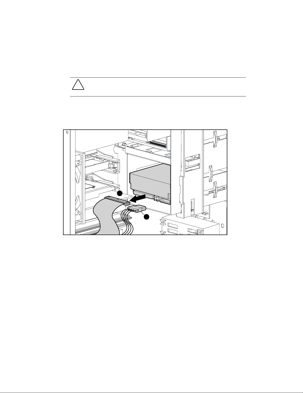
4. Unplug the serial port cover connector from the system board.
Figure 3-26. Removing the serial port cover connector
5. Remove the screw holding the serial port cover connector to the chassis, and lift the plate
out of the chassis.
To replace the serial port cover connector, reverse the above procedure.
NOTE:
The connector is keyed; therefore, locate the key pin header on the system board when
reattaching the serial port cable.
Page 61

3-28
Compaq Professional Workstation AP550 Maintenance and Service Guide
Card Guide
To remove the card guide:
1. Perform the steps in the “Service Preparations” section as previously shown.
CAUTION:
turned off, all cables are disconnected from the back of the workstation, and the power cord is
disconnected from the grounded AC outlet.
Before removing the workstation access panel, ensure that the workstation is
2. Remove the workstation access panel.
3. Remove any full-length expansion boards.
4. Push down on the two tabs on the top of the card guide 1.
5. While holding the tabs down, remove the card guide from the chassis 2.
2
1
Figure 3-27. Removing the card guide
To replace the card guide, reverse the above procedure.
Page 62

Memory Modules
Overview
The Compaq Professional Workstation AP550 supports the following memory modules:
RIMMs
■
Correcting (ECC) Direct Rambus Inline Memory Modules (RIMMs). Additional RIMMs
are available to upgrade the memory. A maximum of 32-count Direct RDRAMs is
supported. The workstation memory includes Dual Direct RDRAM channels with 32-line
cache to store prefetched information.
NOTE:
600-MHz represents the total data transfer rate with a 300-MHz bus.800-MHz represents the
total data transfer rate with a 400-MHz bus.
The workstation has four RIMM sockets on the system board (two per memory channel)
to support a maximum of 2-gigabyte of memory with 256-megabit Direct RDRAM
technology. RIMM modules must be installed in pairs across both channels, for example,
one module in socket XMM1 and the other module in socket XMM3. Each pair of
memory modules must be of the same type, speed, and size. This information can be
found on the label affixed to the RIMM. Continuity RIMMs (CRIMMs) must populate
empty RIMM slots. If CRIMMs are not installed in the empty RIMM sockets, the system
will not boot.
Removal and Replacement Procedures
—The workstation supports 600-MHz and 800-MHz Error Checking and
3-29
DIMMs
■
—Some workstation models come with a synchronous dynamic random access
memory (SDRAM) expansion board installed that supports at least 64-megabyte of Error
Checking and Correcting (ECC). The SDRAM expansion board allows the use of up to
four dual inline memory modules in a RIMM-based system.
Page 63

3-30
Compaq Professional Workstation AP550 Maintenance and Service Guide
RIMM Slot Locations and Configurations
Your workstation supports four RIMM sockets on two Dual Direct RDRAM channels. Both
channels support 32-line cache, which stores prefetched information. A maximum of 32 Direct
RDRAM devices is supported per channel.
The four RIMM sockets are numbered XMM1 and XMM2 (Channel A) and XMM3 and
XMM4 (Channel B).
1 3 42
Figure 3-28. RIMM sockets must be populated in pairs
Table 3-4
RIMM Slot Locations
Identifier Component Memory Channel
1
2
3
4
RIMM Slot XMM2 Channel A
RIMM Slot XMM1 Channel A
RIMM Slot XMM4 Channel B
RIMM Slot XMM3 Channel B
Table 3-5
RIMM Installation Configurations
Memory Channel A Memory Channel B
RIMM Pairs RIMM Slot XMM1 RIMM Slot XMM2 RIMM Slot XMM3 RIMM Slot XMM4
Pair 1 RIMM CRIMM RIMM CRIMM
Pair 2 RIMM RIMM RIMM RIMM
NOTE:
CRIMMs (Continuity RIMMs) must be installed in unpopulated RIMM slots.
Page 64

Removing and Installing RIMMs
Important Guideline for RIMM Installation
Removal and Replacement Procedures
3-31
When installing RIMMs, you
MUST
follow these guidelines:
Table 3-6
RIMM Guidelines
Guideline Comment
Use only 64-, 128-, or 256-MB, 600-MHz or
800-MHz Error Checking and Correcting (ECC)
RIMMs.
Do not mix 600- with 800-MHz RIMMs. Each RIMM pair must be the same type, size, and
Do not exceed 32-count Direct RDRAM devices on
each Direct Rambus channel.
Install RIMMs correctly. Be sure to match the two
Populate unused RIMM sockets with a Continuity
RIMM (CRIMM).
Install RIMM modules in pairs across both channels. RIMM sockets must be populated in the following
DO NOT INSTALL RIMMS THAT DO NOT SUPPORT
ERROR CHECKING AND CORRECTING (ECC).
speed.
A factory label on the RIMM indicates the type, size,
speed, and number of RDRAMS contained on the
RIMM.
key slots
the tab on the RIMM socket. Push the RIMM down
into the RIMM socket, ensuring that it is fully inserted
and properly seated.
If CRIMMs are not in the empty RIMM sockets, the
system will not boot.
order: XMM1 and XMM3 then XMM2 and XMM4.
on the RIMM with
Do not mix RIMMs and DIMMs on the same system
board.
CAUTION:
the workstation will not function.
CAUTION:
use RIMMs with gold metal contacts (not tin-lead) to prevent corrosion and/or oxidation
resulting from having incompatible metals in contact with each other.
CAUTION:
so may damage the module.
NOTE:
The workstation will support up to 2-gigabyte of memory with 256-megabit DRAM technology.
The above guidelines must be followed when installing RIMM modules; otherwise,
RIMM sockets have gold metal contacts. When upgrading memory, it is important to
When handling a memory module, be careful not to touch any of the contacts. Doing
The system will not boot if RIMMs and DIMMs are
mixed on the same board.
Page 65

3-32
Compaq Professional Workstation AP550 Maintenance and Service Guide
RIMM Removal
To remove a RIMM memory module:
IMPORTANT:
RIMM Installation.”
Before installing additional RIMMs, read the previous section, “Important Guidelines for
1. Perform the steps in the “Service Preparations” section as previously shown.
CAUTION:
turned off, all cables are disconnected from the back of the workstation, and the power cord is
disconnected from the grounded AC outlet.
Before removing the workstation access panel, ensure that the workstation is
2. Remove the workstation access panel.
WARNING:
should be exercised whenever removing or replacing these components.
RIMMs can reach a temperature of 212°F (100°C) in a matter of minutes. Caution
3. Press outward on both latches of the RIMM at the same time 1. This releases the module
and pushes it partially out of the socket.
4. Lift the module from the socket 2.
1
Figure 3-29. Removing a memory module
NOTE:
The system recognizes memory upgrades and automatically reconfigures the workstation.
2
1
Page 66

Removal and Replacement Procedures
RIMM Installation
To install a RIMM memory module:
1. Perform the steps in the “Service Preparations” section as previously shown.
3-33
CAUTION:
turned off, all cables are disconnected from the back of the workstation, and the power cord is
disconnected from the grounded AC outlet.
Before removing the workstation access panel, ensure that the workstation is
2. Remove the workstation access panel.
WARNING:
should be exercised whenever removing or replacing these components.
CAUTION:
damage the module.
3. A RIMM can be installed only one way. Be sure to match the two
RIMMs can reach a temperature of 212° F (100° C) in a matter of minutes. Caution
When handling a RIMM, be careful not to touch any of the contacts. Doing so may
key slots
on the RIMM
with the tab on the RIMM socket. Push the RIMM down into the RIMM socket, ensuring
that it is fully inserted and properly seated.
IMPORTANT:
(CRIMMs) must be installed in all unpopulated RIMM slots.
Do not combine different Direct Rambus speeds and capacities. Continuity RIMMs
4. Press both latches inward to secure the module in the socket.
Page 67

3-34
Compaq Professional Workstation AP550 Maintenance and Service Guide
DIMM Location and Configurations
SDRAM Expansion Boards
DIMM-based workstation models come with a synchronous dynamic random access memory
(SDRAM) expansion boards installed that supports at least 64-megabyte of Error Checking and
Correcting (ECC) Dual Inline Memory Modules (DIMMs).
Figure 3-30. Overview of two SDRAM expansion boards installed in alternating RIMM sockets
containing one DIMM on each board
The following configuration guidelines must be followed when replacing SDRAM expansion
boards.
Table 3-7
SDRAM Expansion Boards Configurations
Memory Channel RIMM Slot XMM1 RIMM Slot XMM2 RIMM Slot XMM3 RIMM Slot XMM4
Channel A SDRAM CRIMM
Channel B SDRAM CRIMM
NOTE:
CRIMMs must populate Empty RIMM slots on a system board.
Page 68

Removal and Replacement Procedures
Table 3-8
DIMM Configurations on SDRAM Expansion Board
3-35
SDRAM Expansion Board 1
(RIMM Socket XMM1)
DIMM Pair
Installation Upper DIMM Slot Lower DIMM Slot Upper DIMM Slot Lower DIMM Slot
Pair 1 DIMM DIMM
Pair 2 DIMM DIMM DIMM DIMM
Removing and Installing DIMMs
Important Guidelines for DIMM Installation
When installing DIMMs, you
Guideline Comment
Use only 64-, 128-, 256-, or 512-MB, Registered
100-MHz Error Checking and Correcting (ECC)
DIMMs.
SDRAM expansion boards must be installed in pairs,
populating the RIMM sockets in the following order:
XMM1 and XMM3.
MUST
follow these guidelines:
Table 3-9
DIMM Guidelines
SDRAM Expansion Board 2
(RIMM Socket XMM3)
DO NOT INSTALL DIMMs THAT DO NOT SUPPORT
ERROR CHECKING AND CORRECTING (ECC).
Only two SDRAM expansion boards are supported.
Each SDRAM expansion board supports up to two
DIMMs.
A SDRAM expansion board can only be installed one
way.
Total system support is up to four DIMMs providing
up to 2-GB total memory when four 512-MB DIMMs
are installed.
Be sure to match the two
expansion board with the tab on the RIMM socket.
Push the SDRAM expansion board down into the
RIMM socket, ensuring that it is fully inserted and
properly seated.
key slots
on the SDRAM
continued
Page 69

3-36
Compaq Professional Workstation AP550 Maintenance and Service Guide
Table 3-9
DIMM Guidelines
continued
Guideline Comment
DIMMs must be installed in pairs, alternating
between the two SDRAM expansion boards.
RIMMs and DIMMs can not be mixed on the same
system board.
CRIMMs (Continuity RIMM) must populate the empty
RIMM sockets (XMM2 and XMM4).
When replacing the workstation access panel, the
stabilizer card (attached to the access panel) must
engage the SDRAM expansion boards to balance the
boards.
CAUTION:
or the workstation will not function.
CAUTION:
use SDRAM expansion boards with gold metal contacts (not tin-lead) to prevent corrosion
and/or oxidation resulting from having incompatible metals in contact with each other.
CAUTION:
so may damage the module.
The above guidelines must be followed when installing SDRAM expansion boards,
RIMM sockets have gold metal contacts. When upgrading memory, it is important to
When handling a memory module, be careful not to touch any of the contacts. Doing
DIMM Removal
Compaq recommends populating the lower DIMM slot
on each SDRAM board first, then populating the
upper DIMM slots to upgrade memory.
The system will not boot if RIMMs and DIMMs are
mixed on the same board.
If CRIMMs are not installed in the empty RIMM
sockets, the system will not boot.
To remove a DIMM memory module:
1. Perform the steps in the “Service Preparations” section as previously shown.
CAUTION:
turned off, all cables are disconnected from the back of the workstation, and the power cord is
disconnected from the grounded AC outlet.
Before removing the workstation access panel, ensure that the workstation is
2. Lay the chassis on its side and remove the workstation access panel.
WARNING:
should be exercised whenever removing or replacing these components.
DIMMs can reach a temperature of 212° F (100° C) in a matter of minutes. Caution
Page 70

Removal and Replacement Procedures
3. Press outward on both latches of the RIMM at the same time 1. This releases the
SDRAM expansion board and pushes it partially out of the socket.
4. Lift the expansion board from the socket 2.
2
1
1
3-37
Figure 3-31. Removing a SDRAM expansion board
5. Remove the DIMM module from the SDRAM expansion board by pressing outward on
the latches that hold the DIMM to the expansion board.
DIMM Installation
To install a DIMM memory module:
IMPORTANT:
Guidelines for DIMM Installation.”
1. Perform the steps in the “Service Preparations” section as previously shown.
2. Remove the workstation access panel.
Before installing a SDRAM expansion board, read the previous section, “Important
CAUTION:
turned off, all cables are disconnected from the back of the workstation, and the power cord is
disconnected from the grounded AC outlet.
WARNING:
should be exercised whenever removing or replacing these components.
Before removing the workstation access panel, ensure that the workstation is
DIMMs can reach a temperature of 212° F (100° C) in a matter of minutes. Caution
Page 71

3-38
Compaq Professional Workstation AP550 Maintenance and Service Guide
CAUTION:
contacts. Doing so may damage the module.
When handling a SDRAM expansion board, be careful not to touch any of the
3. Insert the DIMM at a 25-degree angle 1 into the slot on the SDRAM expansion board,
ensuring that it is fully inserted and properly seated.
4. Press both latches inward 2 to secure the DIMM in the SDRAM expansion board.
1
2
2
Figure 3-32. Inserting a DIMM to a SDRAM expansion board
5. Install the SDRAM expansion board in the appropriate RIMM socket on the system board.
Follow the correct configuration guidelines in Table 3-8.
NOTE:
The SDRAM expansion board with an attached DIMM can be installed only one way. Be sure to
match the two
SDRAM expansion board down into the RIMM socket, ensuring that it is fully inserted and properly
seated.
IMPORTANT:
(CRIMMs) must be installed in all unpopulated RIMM slots.
key slots
Do not combine different Direct Rambus speeds and capacities. Continuity RIMMs
on the SDRAM expansion board with the tab on the RIMM socket. Push the
6. Press both latches inward to secure the SDRAM expansion board in the socket.
Page 72

Removal and Replacement Procedures
Figure 3-33. Side access panel with stabilizer card
7. When attaching the workstation access panel, assure the SDRAM expansion board
stabilizer card (attached to the side access panel) engages with the SDRAM expansion
boards, holding the boards in an upright position.
3-39
NOTE:
The system recognizes memory upgrades and automatically reconfigures the workstation.
Page 73

3-40
Compaq Professional Workstation AP550 Maintenance and Service Guide
Processor
Removing a Processor
WARNING:
components to cool before touching.
To reduce the risk of personal injury from hot surfaces, allow the internal system
To remove the processor:
1. Perform the steps in the “Service Preparations” section as previously shown.
CAUTION:
turned off, all cables are disconnected from the back of the workstation, and the power cord is
disconnected from the grounded AC outlet.
Before removing the workstation access panel, ensure that the workstation is
2. Remove the workstation access panel.
CAUTION:
secondary processor
may cause damage to the primary processor.
If two processors are installed and the primary processor needs replacing, the
must
be removed before removing the primary processor. Failure to do so
3. Pull out the retaining tabs on each side of the processor 1, and then lift the processor out
of the socket 2.
1
1
Figure 3-34. Removing the processor from the system board
2
1
To install a new processor, reverse the above procedure.
NOTE:
Before installing a processor, be sure the release latches are in the locked (out) position. This will
cause the latches to click into place when the processor is properly seated.
Page 74

Installing an Additional Pentium III Processor
You can upgrade the workstation to a multiprocessor system. When you install a second
processor, it must be the same speed, cache size, and type as the existing processor. For
comprehensive instructions on installing a second processor, refer to the installation card
provided in the Processor Options Kit.
Removal and Replacement Procedures
3-41
WARNING:
components to cool before touching.
CAUTION:
Compaq recommends that you have a Compaq authorized reseller or service provider install the
processor. If you plan to install a processor yourself, carefully read all the instructions before
you begin.
IMPORTANT:
To reduce the risk of personal injury from hot surfaces, allow the internal system
Installing the processor incorrectly may cause damage to the system board.
An empty processor slot must contain a terminator board.
To install a second Pentium III processor:
1. Turn off the workstation and disconnect the power cord from the grounded AC outlet and
the back of the workstation.
2. Remove the side workstation access panel.
3. Firmly push the processor power module down into processor power module socket.
Figure 3-35. Installing the processor power module for the second processor
4. Assure the latches on the processor power module socket are closed.
Page 75

3-42
Compaq Professional Workstation AP550 Maintenance and Service Guide
5. Pull out the retaining tabs on each side of the terminator board 1, and then lift the
terminator board out of the socket 2.
1
Figure 3-36. Removing the terminator board from the secondary processor slot
2
1
Figure 3-37. Installing a second processor/heatsink assembly
6. Push the processor/heatsink into the secondary processor slot until it locks firmly into
place.
IMPORTANT:
type as the existing processor.
Do not mix processors. The second processor must be the same speed, cache size, and
Reassemble the workstation, and connect the power cord to the grounded AC outlet and to the
workstation.
IMPORTANT:
Be sure to tighten both thumbscrews when replacing the workstation access panel.
Page 76

Removing the Heatsink from the 733-MHz Processor
Removal and Replacement Procedures
3-43
WARNING:
components to cool before touching.
To reduce the risk of personal injury from hot surfaces, allow the internal system
To remove the heatsink from the 733-MHz processor (163363-001):
1. Perform the steps in the “Service Preparations” section as previously shown.
CAUTION:
turned off, all cables are disconnected from the back of the workstation, and the power cord is
disconnected from the grounded AC outlet.
Before removing the workstation access panel, ensure that the workstation is
2. Remove the workstation side access panel.
3. Push the retaining tabs on each side of the processor outward and then lift the processor
out of the socket.
4. Slide the metal clip on the back of the processor to the left 1 and remove the clip.
1
Figure 3-38. Removing the metal clip from the back of the processor clip
Page 77

3-44
Compaq Professional Workstation AP550 Maintenance and Service Guide
5. Lift the processor off the pins on the back of the heatsink to remove it from the
heatsink 2.
Figure 3-39. Removing the metal clip and processor from the heatsink
2
To install a new processor/heatsink, reverse the above procedure.
NOTE:
Before installing a processor, be sure the release latches are in the locked (out) position. This will
cause the latches to click into place when the processor is properly seated.
Page 78

Processor Guide Rails (URM)
Removal and Replacement Procedures
3-45
CAUTION:
beginning these procedures, be sure you are discharged of static electricity by briefly touching
a grounded metal object.
Static electricity can damage the electronic components of the workstation. Before
To remove the processor guide rails:
1. Perform the steps in the “Service Preparations” section as previously shown.
CAUTION:
turned off, all cables are disconnected from the back of the workstation, and the power cord is
disconnected from the grounded AC outlet.
Before removing the workstation access panel, ensure that the workstation is
2. Remove the workstation access panel.
3. Remove the graphics board.
4. Remove the speaker.
5. Remove the processor.
6. Unscrew the clay nuts 1 that secure the processor guide rails to the system board using a
T15 torx drive.
7. Remove the guide rails 2.
2
1
Figure 3-40. Removing the processor guide rails from the system board
To replace the processor guide rails:
1. Align the clay nuts with the threaded studs protruding through the system board.
2. Tighten the clay nuts using a T15 torx drive.
Page 79

3-46
Compaq Professional Workstation AP550 Maintenance and Service Guide
Speaker
To remove the speaker (158267-001):
1. Perform the steps in the “Service Preparations” section as previously shown.
CAUTION:
turned off, all cables are disconnected from the back of the workstation, and the power cord is
disconnected from the grounded AC outlet.
Before removing the workstation access panel, ensure that the workstation is
2. Remove the workstation access panel.
3. Disconnect the speaker cable from the system board.
4. Remove the four screws that secure the speaker to the side of the drive cage 1, and then
remove the speaker 2.
1
2
Figure 3-41. Removing the speaker
To reinstall the speaker, reverse the above procedure.
Page 80

System Board Fan
To remove the system board fan (158275-001):
1. Perform the steps in the “Service Preparations” section as previously shown.
Removal and Replacement Procedures
3-47
CAUTION:
turned off, all cables are disconnected from the back of the workstation, and the power cord is
disconnected from the grounded AC outlet.
Before removing the workstation access panel, ensure that the workstation is
2. Remove the workstation access panel.
3. Unplug the fan from the system board.
4. Remove the four screws that hold the fan to the chassis 1 and lift the fan out of the
unit 2.
5. Remove the four push lock fasteners 3 from the fan assembly.
1
1
2
3
Figure 3-42. Removing the system board fan
To replace the fan, reverse the above procedure, assuring that the fan will push air over the
system board.
Page 81

3-48
Compaq Professional Workstation AP550 Maintenance and Service Guide
Power Supply
To remove the power supply (128399-001):
1. Perform the steps in the “Service Preparations” section as previously shown.
CAUTION:
turned off, all cables are disconnected from the back of the workstation, and the power cord is
disconnected from the grounded AC outlet.
2. Remove the workstation access panel.
3. Disconnect all power cables from the mass storage devices and the system board.
Before removing the workstation access panel, ensure that the workstation is
Page 82

Removal and Replacement Procedures
4. Remove the four external screws that secure the power supply to the back of the
chassis 1.
NOTE:
The internal screw that secures the power supply to the side of the chassis may not need to be
removed, only loosened.
5. Slide the power supply toward the front of the computer, then lift up, and remove it from
the chassis 2.
1
1
2
3-49
Figure 3-43. Removing the power supply
To replace the power supply, reverse the preceding procedure.
WARNING:
reduce the risk of electrical shock, damage to the equipment, or loss of the data, do not disable
this feature. The grounding type plug is an important safety feature.
WARNING:
the computer until the computer cover is replaced. Connecting the power before replacing the
computer cover can result in personal injury or equipment damage.
CAUTION:
reconnected.
This equipment is designed for connection to a grounded (earthed) outlet. To
Only qualified personnel should perform this procedure. Do not reconnect power to
Damage to the system board could result if the power cables are not properly
Page 83

3-50
Compaq Professional Workstation AP550 Maintenance and Service Guide
Power Switch
CAUTION:
damage the switch components.
The power switch should not be removed from the switch holder. Doing so may
To remove the power switch and switch holder (166925-001):
1. Perform the steps in the “Service Preparations” section as previously shown.
CAUTION:
turned off, all cables are disconnected from the back of the workstation, and the power cord is
disconnected from the grounded AC outlet.
Before removing the workstation access panel, ensure that the workstation is
2. Remove the workstation access panel.
3. Disconnect the power/LED cable from the system board 1.
4. Push the release tab toward the drive bays 2, and then remove the power switch from the
chassis 3.
2
3
1
Figure 3-44. Disconnecting and removing the power switch and switch holder
To reinstall the power switch, reverse the above procedure, pushing the power switch until it
snaps into place.
Page 84

System Board
Removal and Replacement Procedures
3-51
CAUTION:
beginning these procedures, be sure you are discharged of static electricity by briefly touching
a grounded metal object.
Static electricity can damage the electronic components of the workstation. Before
To remove and replace the system board (158272-001):
1. Perform the steps in the “Service Preparations” section as previously shown.
CAUTION:
turned off, all cables are disconnected from the back of the workstation, and the power cord is
disconnected from the grounded AC outlet.
Before removing the workstation access panel, ensure that the workstation is
2. Remove the workstation access panel.
3. With the workstation in the desktop position, remove the speaker.
4. Remove all expansion boards.
5. Disconnect all cables that are attached to the system board.
6. Remove the processor, processor guide rails, and the RIMMs or SDRAM expansion
boards.
7. Remove the Terminator Board (if installed).
Page 85

3-52
Compaq Professional Workstation AP550 Maintenance and Service Guide
8. Remove the retaining screws that secure the system board to the chassis 1.
9. Slide the board 1/2-inch toward the front of the chassis to clear the I/O panel
connectors 2.
10. Tilt the rear of the board up 3, then lift the board up and out of the chassis 4.
1
1
Figure 3-45. Removing the system board from the chassis
1
2
To install a new system board, reverse the above procedure.
CAUTION:
reconnected to the system board.
NOTE:
When installing the system board, properly align the board in the chassis by inserting the screw
nearest the power supply first.
Damage to the system board could result if all the power cables are not properly
4
3
Page 86

I/O Panel
Removal and Replacement Procedures
To remove the I/O panel:
1. Perform the steps in the “Service Preparations” section as previously shown.
3-53
CAUTION:
turned off, all cables are disconnected from the back of the workstation, and the power cord is
disconnected from the grounded AC outlet.
Before removing the workstation access panel, ensure that the workstation is
2. Remove the workstation access panel.
3. Remove all expansion boards.
4. Remove the speaker.
5. Remove the power supply.
6. Disconnect all cables that are attached to the system board.
7. Remove the system board.
8. Remove the I/O panel from the back of the chassis.
Figure 3-46. Removing the I/O panel
To replace the I/O panel, reverse the above procedure.
CAUTION:
reconnected to the system board.
Damage to the system board could result if all the power cables are not properly
Page 87

3-54
Compaq Professional Workstation AP550 Maintenance and Service Guide
Lithium Battery
NOTE:
When replacing a battery, use a CR2032 or equivalent 3-volt lithium coin cell battery.
WARNING:
chemical burn if the battery pack is handled improperly. Do not disassemble, crush, puncture,
short external contacts, dispose of in water or fire, or expose it to temperatures higher than
140ºF (60ºC).
CAUTION:
beginning these procedures, be sure you are discharged of static electricity by briefly touching
a grounded metal object.
NOTE:
It is important to make a diagnostics diskette
creating and using the Compaq Diagnostic Diskette are located on the Compaq website:
www.compaq.com
The system board contains a lithium-ion battery pack. There is a risk of fire and
Static electricity can damage the electronic components of the workstation. Before
before
you install a new battery. Instructions for
To replace the lithium battery (153099-001):
1. Perform the steps in the “Service Preparations” section as previously shown.
CAUTION:
turned off, all cables are disconnected from the back of the workstation, and the power cord is
disconnected from the grounded AC outlet.
Before removing the workstation access panel, ensure that the workstation is
2. Remove the workstation access panel.
3. Locate the battery on the system board.
NOTE:
If you have expansion boards installed, you may need to remove them to gain access to the
battery.
Figure 3-47. Locating the battery on the system board
Page 88

4. Lift the battery out of the holder.
Figure 3-48. Removing the battery
Removal and Replacement Procedures
3-55
To replace the battery, slide the replacement battery into position with the positive side up.
IMPORTANT:
NOTE:
Positive polarity should be positioned up.
The battery holder automatically secures the battery in the proper position.
Page 89

3-56
Compaq Professional Workstation AP550 Maintenance and Service Guide
Converting a Minitower to a Desktop Configuration
To convert a minitower to a desktop configuration:
1. Perform the steps in the “Service Preparations” section as previously shown.
CAUTION:
turned off, all cables are disconnected from the back of the workstation, and the power cord is
disconnected from the grounded AC outlet.
Before removing the workstation access panel, ensure that the workstation is
2. Remove the workstation access panel.
3. Remove the front bezel.
4. Disconnect all power and data cables from the hard drives in the 5.25-inch drive bays.
5. Remove the drives from the 5.25-inch drive bays by lifting the drivelock.
Figure 3-49. Releasing the drives by lifting the drivelock
6. Push the drives from the rear and remove them from the front of the drive bay.
CAUTION:
prevent damage to the drive bezel, push the drives from the rear to remove from the drive bay.
The use of unnecessary force may result in damage to the drives.
When removing the drives, do not pull the drives from the front of the drive bay. To
Page 90

Removal and Replacement Procedures
7. Rotate the drives counterclockwise 90 degrees, then reinstall them into the drive bays.
When the drives are properly inserted, the drivelock will secure them.
3-57
IMPORTANT:
desktop configuration for proper drive clearance and access.
Figure 3-50. Installing a drive in the desktop configuration
The diskette drive should always be placed in the bay nearest the top of the chassis in the
8. Reconnect the power and data cables to the drives.
Page 91

3-58
Compaq Professional Workstation AP550 Maintenance and Service Guide
1
2
Figure 3-51. Rotating the bezel blanks when converting a minitower 1 to a desktop
2
9. Gently pull the subpanel, with the bezel blank secured, away from the front bezel, remove,
and rotate the bezel blank.
CAUTION:
subpanel away at an angle could damage the pins that align it within the front bezel.
Hold the subpanel straight when you pull it away from the front bezel. Pulling the
10. Replace the subpanel and front bezel, ensuring the subpanel and front bezel align properly
with the alignment tabs.
CAUTION:
blanks are in the proper orientation to prevent damage to the alignment pins. See Figure 3-7
for the subpanel keyed-alignment positions.
When replacing the subpanel, be sure the aligning pins and any remaining bezel
11. Reassemble the workstation.
NOTE:
When switching from minitower to desktop orientation, the bezel blank should be switched out
with the replacement provided to ensure that the Compaq logo is properly oriented.
Page 92

Removal and Replacement Procedures
Converting a Desktop to a Minitower Configuration
To convert a desktop to a minitower configuration:
1. Perform the steps in the “Service Preparations” section as previously shown.
3-59
CAUTION:
turned off, all cables are disconnected from the back of the workstation, and the power cord is
disconnected from the grounded AC outlet
Before removing the workstation access panel, ensure that the workstation is
2. Remove the workstation access panel.
3. Remove the front bezel.
4. Disconnect the power and data cables from each drive in the 5.25-inch drive bays.
5. Remove each drive from the 5.25-inch drive bays by pressing the drivelock release button.
Figure 3-52. Releasing the drives with the drivelock release button
6. Push the drives from the rear to remove them from the front of the drive bay.
CAUTION:
the drive bezel, push the drive from the rear to remove from the drive bay. The use of
unnecessary force may result in damage to the drive.
When removing a drive, do not pull on the front of the drive. To prevent damage to
Page 93

3-60
Compaq Professional Workstation AP550 Maintenance and Service Guide
7. Rotate each drive clockwise 90 degrees, then reinstall it into the drive bay.
When the drives are properly inserted, the drivelock will secure them.
IMPORTANT:
three, the bay nearest the internal 3.5-inch drives.
Figure 3-53. Installing a drive in the minitower configuration
For proper placement within the chassis, the diskette drive should always be placed in bay
8. Reconnect the power and data cables to each drive.
Page 94

Removal and Replacement Procedures
9. Gently pull the subpanel, with the bezel blank secured, away from the front bezel and
rotate the bezel blank clockwise 90 degrees.
3-61
CAUTION:
subpanel away at an angle could damage the pin alignment.
Hold the subpanel straight when you pull it away from the front bezel. Pulling the
1
2
Figure 3-54. Rotating the bezel blanks when converting a desktop 1 to a minitower
2
10. Replace the subpanel and front bezel, ensuring the subpanel and front bezel align properly
with the alignment tabs.
CAUTION:
blanks are in the proper orientation to prevent damage to the alignment pins. See Figure 3-7
for the subpanel keyed-alignment positions.
When replacing the subpanel, be sure the aligning pins and any remaining bezel
11. Reassemble the workstation.
NOTE:
When switching from desktop to minitower orientation, the bezel blank should be switched out
with the replacement provided to ensure that the Compaq logo is properly oriented.
Page 95

Overview
Chapter
Diagnostic Tools
This chapter provides information on the following topics to assist you when servicing the
Compaq Professional Workstation AP550:
■
Power-On Self-Test (POST)
■
Troubleshooting Minor Problems
■
Computer Setup and Diagnostics Utilities
4
■
Clearing Configuration Memory
■
Diagnostic Utilities
■
Error Codes
■
ROMPaq
■
Fault Management
■
Compaq Insight Manager
■
Compaq Management Agents for Workstations
■
Compaq Restore CD
■
Compaq Diagnostics for Windows NT
IMPORTANT:
proper service.
Adherence to the procedures and precautions described in this chapter is essential for
Page 96

4-2
Compaq Professional Workstation AP550 Maintenance and Service Guide
Power-On Self-Test (POST)
POST is a series of diagnostic tests that runs automatically when the system is turned on. After
the computer is turned on, POST checks the following assemblies to make sure that the
computer system is functioning properly:
■
Keyboard
■
RIMMs
■
Graphics controller
■
Diskette drives
■
IDE/CD-ROM drive
■
Hard drives
■
Processor
■
Controllers
POST also detects the type of SCSI mass storage devices that are installed in the workstation.
NOTE:
If the Power-On Password is set, a key icon (
You will need to enter the password before continuing. See Chapter 5 for information on deleting or
bypassing the Power-On Password.
) appears on the screen while POST is running.
If POST finds an error in the system, an audible and/or visual message occurs. For explanations
of the error codes and a recommended course of action, see Table 4-1.
Page 97

POST Messages
An error message results if the POST encounters a problem. This test runs when the system is
turned on, checking assemblies within the workstation and reporting any errors found.
Diagnostic Tools
4-3
CAUTION:
should be excised whenever removing or replacing these components.
NOTE:
See Chapter 2 for more information on preparing the workstation for service.
RIMMs can reach a temperature of 212°F (100°C) in a matter of minutes. Caution
Table 4-1
POST Error Messages
Audible Beeps
Error Code
101-ROM Error System ROM checksum
101-Option ROM
Checksum Error
102-System Board
Failure
103-System Board
Failure
150-SafePost Active An add-in card in the system
L=Long S=Short Probable Source of Problem Recommended Action
Option ROM checksum Contact your Compaq
DMA, timers, and so forth Contact your Compaq
Hardware component. Replace the Expansion Cage
appeared not to work correctly.
Contact your Compaq
authorized service provider
authorized service provider
authorized service provider
System Board. Run the
Computer Setup utility.
Reboot the system. If add-in
card requires an unusual
amount of setup time, SafePost
can be disabled in Computer
Setup. Otherwise, remove the
add-in card.
continued
Page 98

4-4
Compaq Professional Workstation AP550 Maintenance and Service Guide
Table 4-1
POST Error Messages
Error Code
continued
Audible Beeps
L=Long S=Short Probable Source of Problem Recommended Action
162-System Options
Error
162-System Options
Not Set
163-Time & Date Not
Set
2S
2S Configuration incorrect.
2S
No diskette drive or mismatch in
drive type.
RTC (real-time clock) battery may
need to be replaced. Battery life
is approximately 5 years.
CMOS jumper may not be
properly installed.
System configuration has
changed since last boot.
Invalid time or date in
configuration memory.
RTC (real-time clock) battery may
need to be replaced. Battery life
is approximately 5 years.
CMOS jumper may not be
properly installed.
Run Computer Setup or
Windows NT utilities.
Run Computer Setup or
Windows NT Workstation
utilities.
First, reset the date and time
under Control Panel. If the
problem persists, replace the
RTC battery. See Chapter 3,
Removal and Replacement
“
Procedures
Clear the configuration memory.
Press F1 and save changes. If
problem persists, replace the
CMOS backup battery.
Set the date and time under
Control Panel. Run Computer
Setup or Windows NT
Workstation utilities.
If the problem persists, replace
the RTC battery. See Chapter 3,
Removal and Replacement
“
Procedures
Clear the configuration memory.
for instructions.
”
for instructions.
”
164-Memory Size
Error
201-Memory Error None RAM failure. Be sure each memory module is
202-Memory Type
Mismatch
2S Memory configuration incorrect. Be sure each memory module is
installed properly. Run
Computer Setup or Windows NT
Workstation utilities.
installed properly.
Replace the RIMMs.
None Invalid memory configuration. Run Computer Setup or
Windows NT utilities.
Replace the RIMMs.
continued
Page 99

Table 4-1
POST Error Messages
Error Code
Diagnostic Tools
continued
Audible Beeps
L=Long S=Short Probable Source of Problem Recommended Action
4-5
207-ECC Corrected
Single Bit Errors in
Memory Module
Socket(s)
212-Failed Processor 1L Processor has failed to initialize.
213-Incompatible
Memory Module in
Memory Module
Socket(s)
214-Memory Device
Failure. Error Code:
XX Memory Module
Sockets(s): XX
301-Keyboard Error None Keyboard failure. Check to see if a key is stuck.
303-Keyboard
Controller Error
2S
None I/O board keyboard controller. Reconnect the keyboard with
A memory error on one of the
installed RIMMs has been
detected and corrected with the
system’s ECC logic. The
workstation will continue to
operate correctly despite this
error.
Memory configuration is not
supported by system firmware.
A specific error has occurred in a
RDRAM device installed in the
identified socket.
Run diagnostics to get more
information.
Replace the RIMMs if error
persists.
Replace the processor and/or
the processor power module.
Remove any newly installed
RIMM(s).
Remove the RIMM device.
Reconnect the keyboard with
the computer turned off.
Replace the keyboard if
necessary.
computer turned off.
Replace the system board.
304-Keyboard or
System Unit Error
404-Parallel Port
Address Conflict
Detected
601-Diskette
Controller Error
None Keyboard failure. Reconnect the keyboard with
the computer turned off.
Replace the keyboard.
Replace the system board.
2S Both external and internal ports
are assigned to parallel port X.
None Diskette controller circuitry or
floppy drive circuitry is incorrect.
Run Computer Setup or
Windows NT utilities.
Run Computer Setup.
Check and/or replace cables.
Replace the diskette drive.
Replace the system board.
continued
Page 100

4-6
Compaq Professional Workstation AP550 Maintenance and Service Guide
Table 4-1
POST Error Messages
Error Code
continued
Audible Beeps
L=Long S=Short Probable Source of Problem Recommended Action
605-Diskette Drive
Type Error
912-The computer
cover has been
removed since last
system startup
1611-Fan failure
detected.
1720-SMART Hard
Drive detects
imminent failure.
1721-SMART SCSI
Hard Drive Detects
Imminent Failure
1771-Primary Disk
Port Address
Assignment Conflict
1772-Secondary
Disk Port Address
Assignment Conflict
1780-Disk 0 Failure IDE hard drive failure Contact your Compaq
1781-Disk 1 Failure IDE hard drive failure Contact your Compaq
2S Mismatch in drive type.
The machine cover has been
removed. Please ensure that any
system access was authorized.
Chassis fan not connected to the
system board.
IDE hard drive(s). Contact your Compaq
SCSI hard drive(s) Contact your Compaq
IDE configuration Run Computer Setup
IDE configuration Run Computer Setup
Run Computer Setup or
Windows NT utilities.
This error is strictly
informational and will be reset
upon the next cold boot.
Reattach chassis fan to the
system board.
authorized service provider.
authorized service provider
authorized service provider
authorized service provider
1782-Disk Controller
Failure
IDE circuitry failure Contact your Compaq
authorized service provider
continued
 Loading...