

Page 1

Professional Workstation AP500
Maintenance and Serv ice Guide
Second Edition (March 1999)
Part Number 338534-002
Spares Part Number 338561- 001
Compaq Computer Corporation
Page 2

Notice
The information in this publ ication is subject to change without notice.
COMPAQ COMPUTER CORPORATION SHALL NOT BE LIABLE FOR TECHNICAL OR
EDITORIAL ERRORS OR OMISSIONS CONTAINED HEREIN, NOR FOR INCIDENTAL OR
CONSEQUENTIAL DAMAGES RESULTING FROM THE FURNISHING, PERFORMANCE, OR
USE OF THIS MATERIAL. THIS INFORMATION IS PROVIDED “AS IS” AND COMPAQ
COMPUTER CORPORATION DISCLAIMS ANY WARRANTIES, EXPRESS, IMPLIED OR
STATUTORY AND EXPRESSLY DISCLAIMS THE IMPLIED WARRANTIES OF
MERCHANTABILITY, FITNESS FOR PARTICULAR PURPOSE, GOOD TITLE AND AGAINST
INFRINGEMENT.
This publication contains i nf ormation protected by copyright. No par t of this publication may be
photocopied or reproduced in any form without prior written consent from Compaq Computer
Corporation.
1999 Compaq Computer Corporation.
All rights reserved. Printed in the U.S.A.
The software described in this guide is f ur nished under a license agreement or nondisclosure agreement.
The software may be used or copied only in accordance with the terms of the agreement.
Compaq, Compaq Insight Manager, ROMPaq, QVision, SmartStar t, NetFlex, QuickFind, PaqFax,
registered United States Patent and Trademark Office.
Netelligent, SoftPaq, QuickBlank, QuickLock, and PowerStorm are trademarks and/or service marks of
Compaq Computer Corporation.
Microsoft, MS-DOS, Windows, and Windows NT are registered trademarks of Microsoft Corporation.
Other product names mentioned herein may be trademarks and/or registered trademarks of their respect ive
companies.
Compaq Professional Workstation AP500 Maintenance and Service Guide
Second Edition (March 1999)
Part Number 338534-002
Spare Part Number 338561-001
Page 3

Contents
About This Guide
Text Conventions.......................................................................................................................vii
Symbols in Text........................................................................................................................viii
Symbols on Equipment.............................................................................................................viii
Where to Go for Additional Help...............................................................................................ix
Other Information Sources..................................................................................................ix
Telephone Numbers.............................................................................................................ix
Chapter 1
Illustrated Parts Catalog
Mechanical Parts ......................................................................................................................1-1
System Components .................................................................................................................1-2
Spares Parts List.......................................................................................................................1-3
Chapter 2
Service Preliminaries
Compaq Technician Notes........................................................................................................2-1
Preliminary Warnings and Cautions.........................................................................................2-2
Electrostatic Discharge Information.........................................................................................2-3
Equipment Symbols..................................................................................................................2-3
Tools and Software Requirements............................................................................................2-4
Warranty Information...............................................................................................................2-4
iii
Chapter 3
Removal and Replacement Procedures
Serial Number...........................................................................................................................3-1
Service Preparations.................................................................................................................3-2
Cable Lock ...............................................................................................................................3-3
Workstation Feet.......................................................................................................................3-4
Side Access Panel.....................................................................................................................3-5
Front Bezel...............................................................................................................................3-6
Blank Drive Bezel....................................................................................................................3-7
EMI/Cooling Shield..................................................................................................................3-8
Speaker.....................................................................................................................................3-9
I/O Bracket Assembly ............................................................................................................3-10
Replacing the I/O Bracket Assembly...............................................................................3-11
Expansion Boards...................................................................................................................3-12
Identifying the PCI and ISA Expansion Slots..................................................................3-12
Removing a PCI or ISA Expansion Board......................................................................3-14
Removing a Symbios Wide Ultra2 PCI SCSI Controller ................................................3-15
Removing the Accelerated Graphics Port (AGP) Graphics Controller............................3-16
Removing the Card Guide...............................................................................................3-17
Removing the Backplane Board......................................................................................3-18
System Fan.............................................................................................................................3-19
Compaq Professional Workstation AP500 Maintenance and Service Guide
Page 4

iv
Removal and Replacement Procedures continued
Mass Storage Devices.............................................................................................................3-21
Drive Positions................................................................................................................3-21
Hardware Screws............................................................................................................. 3-23
CD-ROM Drive or DVD-ROM Drive.............................................................................3-24
Diskette Drive .................................................................................................................3-26
Removing a 7200 rpm Hard Drive from Bays 5 or 6.......................................................3-28
Removing a 10,000-rpm Hard Drive from Bays 5 or 6...................................................3-31
Removing the Fan from a Hard Drive Installed in Bays 5 or 6 ......................................3-35
Removing a Hard Drive from the Removable Hard Drive Cage.....................................3-37
Installing a Hard Drive in the Removable Hard Drive Cage...........................................3-39
SCSI Cables and Guidelines...................................................................................................3-41
SCSI Cables.....................................................................................................................3-41
SCSI Guidelines for Installing SCSI Devices..................................................................3-42
SCSI Guidelines for Optimizing Performance ................................................................3-42
System Board Assembly.........................................................................................................3-43
System Board with Tray and Cage..................................................................................3-43
System Board Components..............................................................................................3-45
Dual Inline Memory Modules (DIMMs).........................................................................3-46
Important Guidelines for DIMM Installation ..................................................................3-46
Removing a DIMM.........................................................................................................3-47
Processor and Heatsink Assembly..........................................................................................3-48
Processor Power Module.................................................................................................3-49
Primary Processor Power Module Cable Insulator..........................................................3-50
External Battery......................................................................................................................3-51
Running Computer Setup ................................................................................................3-51
Installing the Battery.......................................................................................................3-52
Power Switch Cable Assembly...............................................................................................3-54
Power Supply..........................................................................................................................3-55
Chapter 4
Diagnostic Tools
Power-On Self-Test (POST).....................................................................................................4-2
POST Messages........................................................................................................................4-3
Troubleshooting Minor Problems.............................................................................................4-7
Power Problems.................................................................................................................4-8
Diskette Drive Problems....................................................................................................4-9
Display Problems ............................................................................................................4-10
Printer Problems..............................................................................................................4-11
Hard Drive Problems.......................................................................................................4-12
Hardware Installation Problems ......................................................................................4-13
CD-ROM Drive and DVD-ROM Drive Problems ..........................................................4-14
Memory Problems...........................................................................................................4-15
SCSI Problems................................................................................................................4-15
Network Problems...........................................................................................................4-16
Audio Hardware Conflicts...............................................................................................4-18
Page 5

Diagnostic Tools continued
Compaq Setup and Diagnostics Utilities.................................................................................4-19
Accessing the Compaq Utilities Menu............................................................................4-19
Creating a Diagnostics Diskette.......................................................................................4-20
Computer Setup...............................................................................................................4-21
Computer Checkup (TEST).............................................................................................4-23
View System Information (INSPECT)............................................................................4-24
Managing a Diagnostics Partition....................................................................................4-25
Diagnostic Error Codes...........................................................................................................4-25
Microprocessor................................................................................................................4-26
Memory...........................................................................................................................4-27
Keyboard.........................................................................................................................4-27
Printer.............................................................................................................................. 4-28
Diskette Drive .................................................................................................................4-28
Serial Port........................................................................................................................4-29
Modem ............................................................................................................................4-29
Pointing Device...............................................................................................................4-29
CD-ROM Drive (IDE).....................................................................................................4-30
Tape Drive.......................................................................................................................4-30
Video...............................................................................................................................4-31
Audio...............................................................................................................................4-33
Network Interface............................................................................................................4-33
SCSI Error Codes...................................................................................................................4-34
Upgrading the ROM...............................................................................................................4-37
Local ROM Upgrade.......................................................................................................4-37
Remote ROM Flash.........................................................................................................4-38
FailSafe Boot Block ROM......................................................................................................4-39
Compaq Insight Manager .......................................................................................................4-41
Compaq Workstation SSD for Windows NT ..........................................................................4- 42
Remote Capability...........................................................................................................4-42
Silent Setup Command Line Interface.............................................................................4-42
Compaq Diagnostics for Windows NT...................................................................................4-43
v
Chapter 5
System Security
Security Features......................................................................................................................5-1
Password Security.............................................................................................................5-2
Windows NT Workstation Password.................................................................................5-6
National Keyboard Delimiter Characters ..........................................................................5-6
Advanced Security Management..............................................................................................5-7
Re-enabling Diskette Boot or Diskette Write....................................................................5-7
Re-enabling a Serial Port or Parallel Port..........................................................................5-8
QuickLock/QuickBlank.....................................................................................................5-8
Cable Lock Provision........................................................................................................5-9
Compaq Professional Workstation AP500 Maintenance and Service Guide
Page 6

vi
Chapter 6
Jumper and Switch Information
Battery Jumpers........................................................................................................................6-2
Switch Settings.........................................................................................................................6-3
Hard Drives..............................................................................................................................6-4
32X Max CD-ROM Drive (IDE)..............................................................................................6-4
PowerStorm 300/AGP Graphics Controller..............................................................................6-5
Chapter 7
Physical and Operating Specifications
System Unit..............................................................................................................................7-2
325W Power Supply.................................................................................................................7-7
Diskette Drive...........................................................................................................................7-8
Zip Drive..................................................................................................................................7-9
CD-ROM Drive......................................................................................................................7-10
DVD-ROM Drive...................................................................................................................7-12
Hard Drives............................................................................................................................7-14
Audio System.........................................................................................................................7-19
Keyboard................................................................................................................................7-19
Mouse.....................................................................................................................................7-20
Graphics Controllers...............................................................................................................7-21
Network Controller.................................................................................................................7-25
RJ-45 Network Cable Specifications......................................................................................7-25
Chapter 8
External Connectors
Physical Location.....................................................................................................................8-1
Pin Assignments.......................................................................................................................8-3
Index
Page 7
About This Guide
This guide is designed to be used as step-by-step instructions for installation, and as a reference for
operation, troubleshooting, and future upgrades.
IMPORTANT: The installation of options and servicing of this product should be performed
by individuals that are knowledgeable of the procedures, precautions, and hazards
associated with equipment containing hazar dous energy circuits.
vii
WARNING: Only authorized technicians trained by Compaq should attempt to
repair this equi pment. All troubleshooting and repair pr ocedures are detailed to
allow only subassembly/module level repair. Because of the complexity of the
individual boards and subassemblies, no one should attempt to make repairs at
the component level or make modifications to any printed wiring board. Improper
repairs can create a safety hazard. Any indications of component replacement or
printed wiring boa rd modifications may void any warranty.
WARNING: To reduce the risk of personal injury from electrical shock and
hazardous energy levels, only authorized service technicians should attempt to
repair this equi pment. Improper repairs could create conditions that are
hazardous.
Text Conventions
This document uses the following conventions to distinguish e l ements of text:
Keys Keys appear in boldface. A plus sign (+) between two
keys indicates that they should be presse d simultaneously.
USER INPUT User input appears in a different typeface and in
uppercase.
FILENAMES File names appear in upperca se italics.
Menu Options,
Command Names,
Dialog Box Names
COMMANDS,
DIRECTORY NAMES,
and DRIVE NAMES
Type When you are instructed to type information, type the
Enter When you are instructed to enter information, type the
These appear in initial capital letters.
These always appea r in uppercase.
information without pressing the Enter key.
information and then press the Ent e r key.
Compaq Professional Workstation AP500 Maintenance and Service Guide
Page 8
viii
Symbols in Text
These symbols may be found in the te xt of this guide. They have the following meanings.
!
IMPORTANT: Presents clarifying information or specific instructions.
NOTE: Presents commentary, sidelights, or interesting points of information.
WARNING: Indicates that failure to follow directions in the warning could result in
bodily harm or loss of life.
CAUTION: Indicates that failure to follow directions could result in damage to
equipment or loss of information.
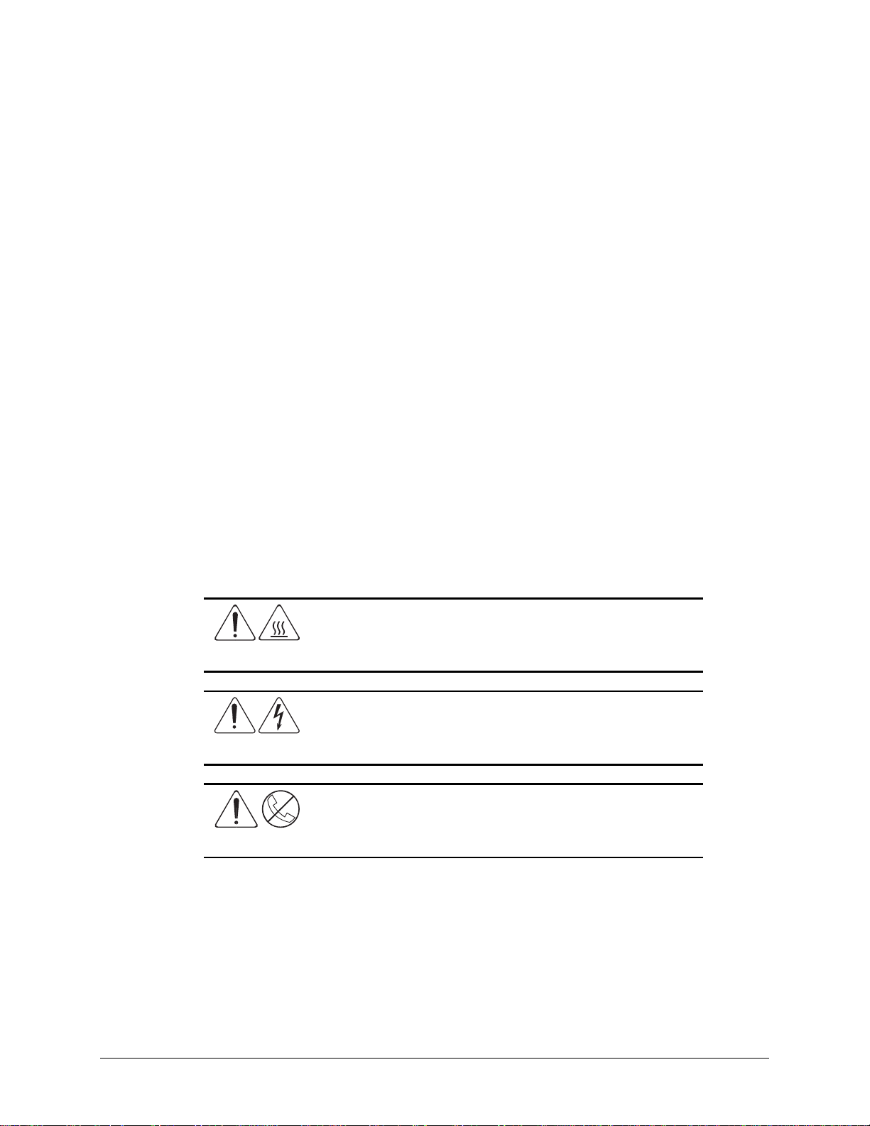
Symbols on Equipment
These icons may be located on equipment in areas where hazardous conditions may exist.
Any surface or area of the equipment marked with these symbols
indicates the presence of electrical shock hazards. Enclosed area
contains no operator serviceable parts.
WARNING: To reduce risk of injury from electrical shock hazards, do
not open this enclosure.
Any RJ-45 receptacle marked with these symbols indicates a Network
Interface Connection.
WARNING: To reduce risk of electrical shock, fire, or damage to the
equipment, do not plug telephone or telecommunications connectors
into this receptacle.
Any surface or area of the equipment marked with these symbols
indicates the presence of a hot surface or hot component. If this
surface is contacted, the potential for injury exists.
WARNING: To reduce the risk of injury from a hot component, allow
the surface to cool before touching.
Page 9

Where to Go for Additional Help
Major sources of additional information are listed below.
Other Information Sources
In addition to this guide, the following information sources are available:
■ User Documentation
■ Compaq Service Quick Refere nce Guide
■ Service Training Guides
■ Compaq Service Advisories and Bulletins
■ Compaq QuickFind
■ Compaq Insight Manager
■ Compaq Download Facility: Call 1-281-518-1418.
Telephone Numbers
ix
For the name of your nearest Compaq Authorized Reseller:
In the United States, call 1-800-345-1518.
In Canada, call 1-800- 263-5868.
For Compaq technical support:
In the United States and Canada, call 1-800-OK-COMPAQ (For continuous qua lity improvement,
calls may be recor ded or monitored.)
For Compaq technical support phone num bers outside the United States and Canada, visit the
Compaq website at:
www.compaq.com
Compaq Professional Workstation AP500 Maintenance and Service Guide
Page 10
Chapter 1
Illustrated Parts Catalog
This chapter provides an illustrated parts breakdo wn and a reference for spare parts for the
Compaq Professional Workstation AP500.
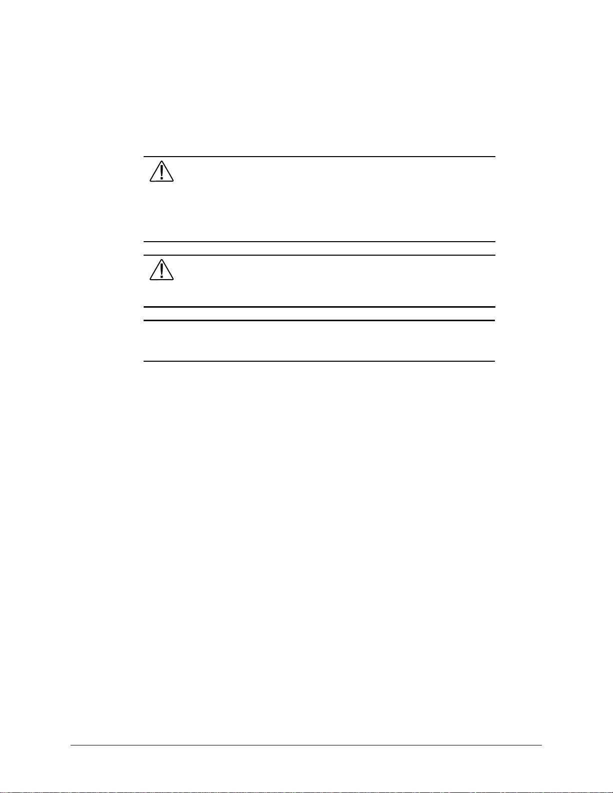
Mechanical Parts
1-1
100
11
12
10
49
24
100
9
4 98
6
2
1
Figure 1-1. Exploded view of the Compaq Professional Workstation AP500 mechanical parts
Compaq Professional Workstation AP500 Maintenance and Service Guide
Page 11
1-2 Illustrated Parts Catalog
13
66
16
17
14
19 20
8
11
26
42
33
7
32
98
23
3
50
52
22
51
74
5
44 45
87
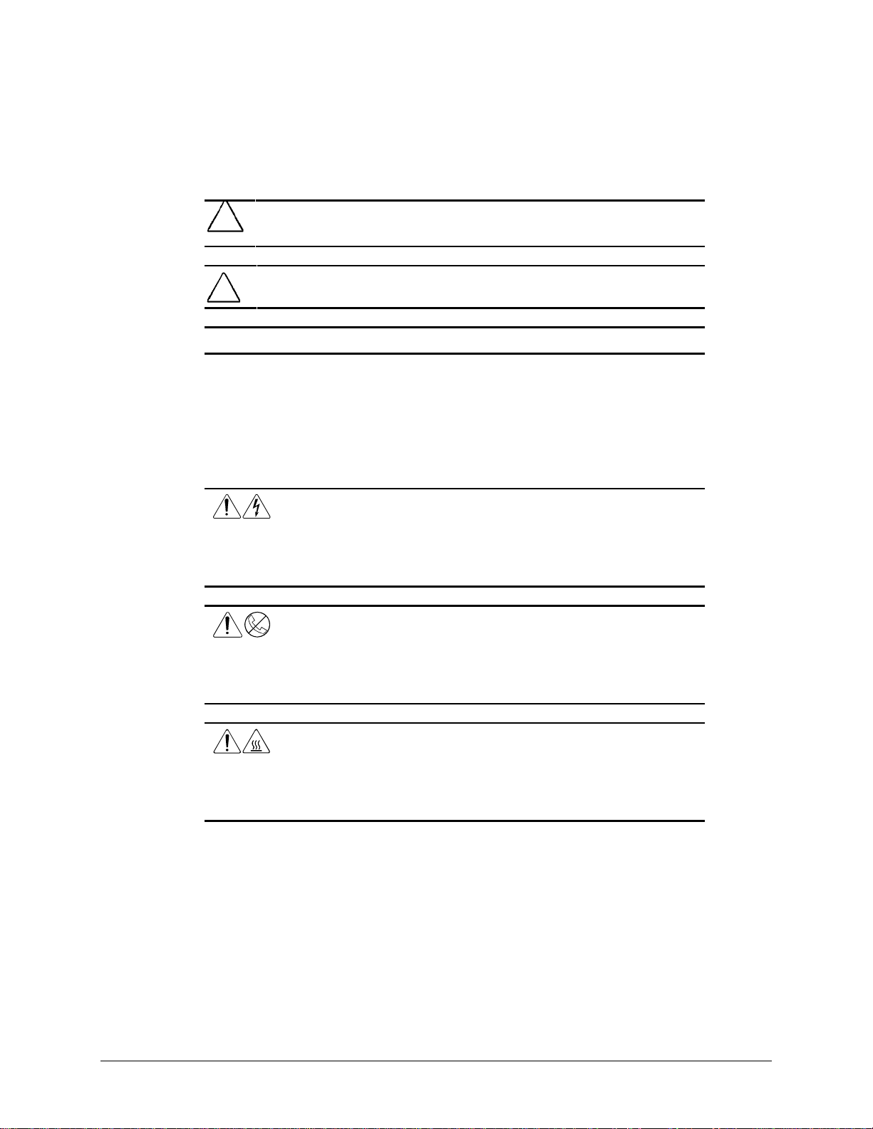
System Components
Figure 1-2. Exploded view of the Compaq Professional Workstation AP500 system components
Page 12

Spares Parts List
Parts or components marked with an asterisk (*) are not illustrated.
Reference Description Spares Part #
MECHANICAL
1 Side Access Panel 329263-001
2 Front Bezel 338549-001
3 I/O Bracket (Expansion Board Assembly) 338563-001
4 Blank Drive Bezel (part of the Miscellaneous Plastic Kit) 329265-001
5 Backplane Board 338513-001
6 Hood 338565-001
7 Removable Hard Drive Cage 338557-001
1-3
Table 1-1
Compaq Professional Workstation AP500
Spares Parts List
SYSTEM
8 Speaker 328730-001
9 EMI/Cooling Shield (part of the Miscellaneous Hardware Kit) 338559-001
10 Workstation Feet 329264-001
11 Chassis 338547-001
12 System Fan (fan bracket included in Miscellaneous Hardware Kit) 338558-001
13 Power Supply, 325W 328563-001
14 System Board with Tray 400-, 450-, 500-MHz 402124-001
15 System Board with Tray 400-, 450-MHz 338548-001*
16 Intel Pentium II Processor, 400/100 MHz, 512K with heatsink 327648-001
17 Intel Pentium II Processor, 450/100 MHz, 512K with heatsink 328785-001
18 Intel Pentium III Processor, 500/100 Mhz, 512K with heatsink 116402-001*
19 Processor Power Module (Voltage Regulator Module)
For 350/400/450/500 MHz CPU
20 Processor Power Module (Voltage Regulator Module)
For 350/400/450 MHz CPU
329267-001
327660-001
21 Lock Security Bracket 199109-001*
Compaq Professional Workstation AP500 Maintenance and Service Guide
Continued
Page 13

1-4 Illustrated Parts Catalog
Compaq Professional Workstation AP500 Spares Parts List
Reference Description Spares Part #
22 External Battery 160274-001
23 Expansion Board Slot Cover 141081-001
24 Power Switch and LEDs with Cable 329270-001
MEMORY
25 32-MB Memory Module (Registered 100-MHz SDRAM) 317747-001*
26 64-MB Memory Module (Registered 100-MHz SDRAM) 317745-001
27 128-MB Memory Module (Registered 100-MHz SDRAM) 317756-001*
28 256-MB Memory Module (Registered 100-MHz SDRAM) 317749-001*
MASS STORAGE
29 4.3-GB Wide Ultra2 SCSI Hard Drive 7200 rpm 349533-001*
30 4.3-GB Wide Ultra2 SCSI Hard Drive 10,000 rpm 386538-001*
31 9.1-GB Wide Ultra2 SCSI Hard Drive 7200 rpm 349534-001*
32 9.1-GB Wide Ultra2 SCSI Hard Drive 10,000 rpm 386539-001
Continued
33 18-GB Wide Ultra2 SCSI Hard Drive 10,000 rpm 386540-001
34 4.3-GB Wide-Ultra SCSI Hard Drive, 7200 rpm 339514-001*
35 4.3-GB Wide-Ultra SCSI Hard Drive, 10,000 rpm 336383-001*
386539-001*
36 9.1-GB Wide-Ultra SCSI Hard Drive 7200 rpm 339515-001*
37 9.1-GB Wide-Ultra SCSI Hard Drive 10,000 rpm 336384-001*
38 18-GB Wide-Ultra SCSI Hard Drive 10,000 rpm 336385-001*
39 6.4-GB Ultra ATA Hard Drive 166973-001*
40 10-GB Ultra ATA Hard Drive, 7200 rpm 330520-001*
41 Symbios Wide Ultra2 PCI SCSI Controller 114009-001*
42 1.44-MB Diskette Drive 179161-001
43 100-MB Zip Drive 401624-001*
44 32X Max CD-ROM Drive (IDE) 327659-001
45 DVD-ROM Drive 105771-001
46 12/24-GB DAT Drive 340593-001*
Continued
Page 14

1-5
Compaq Professional Workstation AP500 Spares Parts List
Reference Description Spares Part #
47 4/8-GB SLR Drive 340591-001*
48 Hard Drive Mounting Bracket (Bays 5 and 6) 243231-001*
49 Fan and Cable for >7200 rpm Hard Drives Installed in Bay 5 or 6 329266-001
CABLE KITS
50 Miscellaneous Signal Cable Kit (CD-ROM Drive, HD, Diskette, Audio) 327649-001
51 SCSI cable, wide 338546-001
52 Wide Ultra2 SCSI cable 402222-001
53 SCSI adapter, 50- to 68-Pin (internal) 189638-001*
KEYBOARD AND MOUSE
54 Keyboard 269513-001*
55 3-Button Mouse 327716-001*
MONITOR
56 P75 Monitor 307815-xxx*
Continued
57 V75 Monitor 307713-xxx*
58 V90 Color Monitor 305602-xxx*
59 P900 Color Monitor 303502-xxx*
60 P1610 Monitor 305710-xxx*
61 P110 Monitor 284959-xxx*
62 TFT 5000:
Opal, TS, NA, TC099
Carbon, TS, NA, TC099
63 TFT 8000:
Opal, no protective panel, TC095, WW
Opal, with protective panel, TC095, WW
Carbon, no protective panel, TC095, WW
Carbon, with protective panel, TC095, WW
64 TFT 450:
Order TFT 450 spare part from the TFT 450 guide
115714-001*
115712-001*
307911-001*
102358-B24*
102359-B24*
102356-B24*
(PN 170431-001)*
65 TFT 500:
Order TFT 500 spare part from the TFT 500 guide
(PN 285012-001)*
Continued
Compaq Professional Workstation AP500 Maintenance and Service Guide
Page 15

1-6 Illustrated Parts Catalog
Compaq Professional Workstation AP500 Spares Parts List
Reference Description Spares Part #
GRAPHICS
66 GLoria Synergy+ Graphics Controller 4-MB (AGP) 327599-001
67 GLoria Synergy+ 4-MB Memory Upgrade 327600-001*
68 GLoria Synergy+ 8 MB (PCI) Graphics Controller 298796-001*
69 PowerStorm 300 Graphics Controller (AGP) 338539-001*
70 Matrox Millennium G200 Graphics Controller 294409-001*
71 Matrox Millennium G200 8-MB Memory Upgrade 386047-001*
72 Matrox Productiva G100 Multi-Monitor Series Graphics Controller 101239-001*
CONTROLLERS
73 Compaq SMART-2SL Array Controller 242777-001*
74 Dual-Channel SCSI Controller 295626-001*
COMMUNICATIONS
75 Netelligent 16/4 TR PCI IBM UTP/STP Controller 301210-001*
Continued
76 Netelligent 16/4 TR PCI UTP/STP Controller 268010-001*
77 Netelligent 10 T/2 PCI UTP/Coax Controller 292857-001*
78 Netelligent 10 T/2 ISA UTP/Coax Controller 265618-001*
79 Netelligent 100 FDDI PCI SAS Fiber-SC 242506-002*
80 Netelligent 100 FDDI PCI DAS Fiber-UTP 242506-003*
81 Netelligent 100 FDDI PCI SAS Fiber-UTP 242506-004*
82 Netelligent 100 FDDI PCI SAS Fiber-MIC 242506-005*
83 Netelligent 56K PCI Fax Modem 321510-B21*
84 Netelligent 56K ISA Fax Modem 294912-001*
85 Compaq Fast Ethernet NIC NC3122 317453-001*
86 Compaq Fast Ethernet NIC NC3120 317606-001*
87 Compaq Ethernet NIC NC1120 317358-001
88 Compaq Fast Ethernet NIC NC3161 323556-001*
Continued
Page 16

1-7
Compaq Professional Workstation AP500 Spares Parts List
Reference Description Spares Part #
SOFTWARE
89 Magellan Driver CD 297863-001*
90 Spaceball Driver CD 298033-001*
91 Microsoft Windows NT Workstation 4.0 CD 275573-xxx*
92 Compaq SmartStart for Workstations CD 275574-xx3/xx2(SP)*
93 Systems ROMPaq 275595-001*
94 Compaq Setup and Compaq Diagnostics for Workstations Diskette 275575-xxx*
MISCELLANEOUS
95 Magellan 3D Pointing Device (spacemouse) 297645-001*
96 Spaceball 3D Pointing Device 297644-001*
97 Compaq Multimedia Sound System (US) 294122-xxx*
98 Miscellaneous Plastic Kit (includes baffles*, card guide and
blank drive bezel)
99 Heatsink Bridge 327658-001*
Continued
329265-001
100 Miscellaneous Hardware Kit (includes EMI/Cooling Shield and System Fan
101 Rack Mounting Kit 338556-001*
102 Shipping Box with Buns (US) 329268-001*
103 Shipping Box with Buns (INTL) 329268-002*
104 SCSI Adapter, 68- to 50-Pin (external) 270229-001*
DOCUMENTATION
105 Maintenance and Service Guide 338561-001*
106 Illustrated Parts Map 338560-001*
107 Service Quick Reference Guide (revision -038 or later) 162212-001*
338559-001
Bracket)
Compaq Professional Workstation AP500 Maintenance and Service Guide
Page 17
Chapter 2
Service Preliminaries
This chapter identifies the following service considerations:
■ Preliminary warnings and cautions
■ Electrostatic discharge information
■ Equipment symbols
■ Tools and software requirements
■ Warranty information
IMPORTANT: Adherence to the procedures and precautions described in this chapter is
essential for proper service.
Compaq Technician Notes
WARNING: To reduce the risk of personal injury from electrical shock and
hazardous energy levels, do not exceed the level of repair specified in these
procedures. Because of the complexity of the individual boards and
subassemblies, do not attempt to make repairs at the component level or make
modifications to a ny printed wiring board. Improper repairs could create conditions
that are hazardous.
2-1
WARNING: To reduce the risk of electric shock or damage to the equipment:
Disconnect power from the computer by unplugging the power cord from either
the electrical outlet or the computer.
Do not disable the power cord grounding plug. The grounding plug is an important
safety feature.
Plug the AC adapter or power cord into a grounded (earthed) elec trical outlet that
is easily accessible at all times.
CAUTION: To properly ventilate the system, you must provide at least 6 inches
(15 cm) of clearance at the front of the workstation and 3 inches (7.6 cm) at the
back.
IMPORTANT: Any indication of repair at the component level or modification of a printed
wiring board ma y void any warranty.
Compaq Professional Workstation AP500 Maintenance and Service Guide
Page 18
2-2 Service Preliminaries
Preliminary Warnings and Cautions
The following should be noted when operating or servicing the Compaq Professional
Workstation AP500:
WARNING: To reduce the risk of electric shock or damage to the equipment:
■ Disconnect power from the system by unplugging all power cords
from either the electrical outlet or the Compaq Professional
Workstation AP500.
■ Do not disable the power cord grounding plug. The ground plug is
an important safety feature.
■ Plug the power cord into a grounded (earthed) electrical outlet that
is easily accessible at all times.
WARNING: To reduce the risk of personal injury from hazardous energy levels,
only authorized service technicians should attempt to repair this equipment.
Because of the complexity of the individua l boards and subassemblies, no one
should attempt to make repairs at the component level or to make modifications to
any printed wiring board. Improper repairs can create a safety hazard.
CAUTION: The power supply in the Compaq Professional Workstation AP500 has
an auxiliary power section. This section is always active as long as the unit is
plugged into a live AC outlet. Be sure to turn off the switch and unplug the power
cord before performing any service work.
CAUTION: To properly ventilate the system, you must provide at least 6 inches
(15 cm) of clearance at the front of the workstation and 3 inches (7.6 cm) at the
back.
IMPORTANT: Any indications of component replacement or printed wiring board
modifications may void any warranty.
Page 19
Electrostatic Discharge Information
A discharge of static electricity can damage static-sensitive devices or micro-circuitry. Proper
packaging and grounding techniques are necessary precautions to prevent damage. To prevent
electrostatic damage, observe the following precautions:
■ Transport products in static-sa fe containers (conductive tube s, bags, or boxes).
■ Keep electrostatic-sensitive parts in their containers until they arrive at static-free stations.
■ Cover workstations with approved static-dissipating material. Provide a wrist strap
connected to the work surface and properly grounded tools and equipment.
■ Keep work area free of non-conductive mater i als such as ordinary plastic assem bly a i ds
and foam packing.
■ Be sure you are always prope rly grounded when touching a static-sensitive component or
assembly.
■ Avoid touching pins, leads, or circuitry.
■ Always place drives PCB assembly-side down.
■ Use conductive field servic e tools.
2-3
Equipment Symbols
The following symbols are locat ed on applicable components of the worksta tion and should be
observed when servicing the workstation to avoid personal injury or damage to the components:
WARNING: Any surface or area of the equipment marked with these
symbols indicates the presence of a hot surface or hot component. If this
surface is contacted, the potential for injury exists. To reduce risk of
injury from a hot component, allow the surface to cool before touching.
WARNING: Any surface or area of the equipment marked with these
symbols indicates the presence of electrical shock hazards. Enclosed
area contains no operator serviceable parts. To reduce risk of injury from
electrical shock hazards, do not open this enclosure.
WARNING: Any RJ-45 receptacle marked with these symbols
indicates a Network Interface Connection. To reduce risk of electrical
shock, fire, or damage to the equipment, do not plug telephone or
telecommunications connectors into this receptacle.
Compaq Professional Workstation AP500 Maintenance and Service Guide
Page 20

2-4 Service Preliminaries
Tools and Software Requirements
To service the workstation, you mi ght need:
■ Torx T-10 screwdriver
■ Torx T-15 screwdriver
■ Flat-blade screwdriver
■ Compaq Setup and Diagnostics Utility
IMPORTANT: Prior to servicing the workstation, be sure the drivers from the latest Compaq
Workstation SSD for Windows NT are installed. See Chapter 4 for installation procedures.
Warranty Information
The following warranties come standard with the workstation:
■ Standard Warranty—a three-year limited warranty that cover s three years on parts, one
year on labor carry-in, and one year of onsite service
■ Pre-Failure Warranty—a special warranty that extends the Compaq three-year limited
warranty by applying it to critical system components before they fail. This warranty
ensures that when you receive notification of a pre-failure condition through Compaq
Insight Manager or the Windows NT Event Log, the component is replaced under
warranty.
NOTE: For more information about Compaq Insight Manager, see Chapter 4.
The Pre-Failure War ranty covers the following workstation c omponents:
❏ SCSI hard drives
❏ Error Correcting Code (ECC) memory
❏ Pentium II processor
❏ Pentium III Processor
In addition to the above warrantie s, an optional Extended Warranty is available. If purchased,
this warranty extends the Standar d Warranty’s one year coverage for labor and onsite ser vic e for
two additional years.
IMPORTANT: Observe all warnings and cautions provided herein. Failure to do so may
void warranty for damaged components.
Page 21
Chapter 3
Removal and Replacement Procedures
This chapter provides subassembly/module-level removal and replacement pr ocedures for the
Compaq Professional Workstation AP500.
After completing all necessary removal and replacement procedures, run the Compaq Setup and
Diagnostics program to veri fy that all components are oper ating properly.
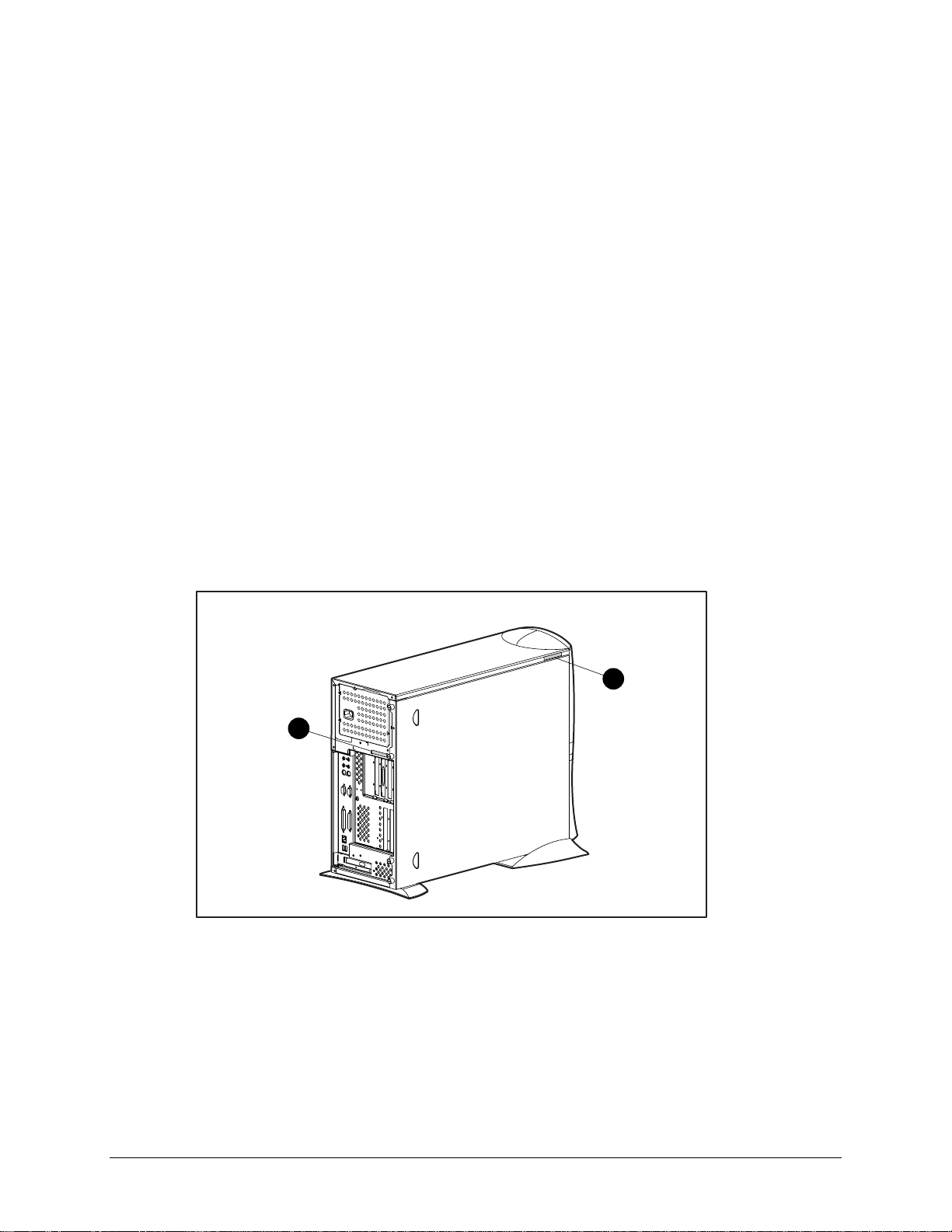
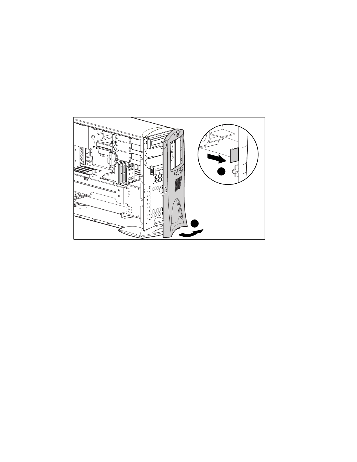
Serial Number
Provide the computer serial number to Compaq whe never you request information or order spare
parts. The serial number is located on the top right side of the workstation 1 and also on the rear
of the chassis 2.
For asset control, the seria l number is also embedded in the EP RO M on the system board. If the
system board is replaced with a spare part from Compaq, an invalid serial number condition will
be reported during POST. T o c l ear the condition, use Compaq Softpa q SP8410. It is located at:
http://www.compaq.com/support/files/workstations/us/software/674.html.
3-1
NOTE: If a system board from another workstation is installed, POST recognizes the serial
number as a val id number.
1
2
Figure 3-1. Identifying serial number locations
Compaq Professional Workstation AP500 Maintenance and Service Guide
Page 22
3-2 Removal and Replacement Procedures
Service Preparations
CAUTION: The power supply in the Compaq Professional Workstation AP500 has
an auxiliary power section. This section is always active as long as the unit is
plugged into a live AC outlet. Be sure to turn off the switch and unplug the power
cord before performing any service work.
CAUTION: Electrostatic discharge can damage electronic components. Be sure
you are properly grounded before beginning any install ation procedure. See
“Electrostatic Discharge Information” in Chapter 2 for more information.
Before beginning any of the removal and replacement procedures, complete the following steps:
1. Turn off the workstation.
2. Disconnect the power cord from the grounded AC outlet and then from the workstation.
3. Turn off all peripheral devices and disconnect cables f rom the rear of the wor ksta tion.
4. Remove the cable lock in order to access internal components. See the following section
for instructions on how to remove the cable lock.
Page 23
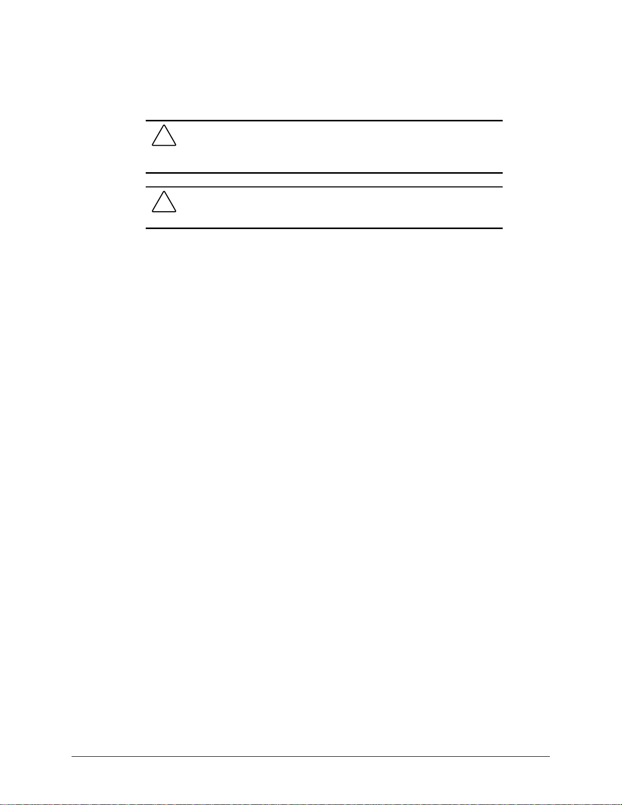
Cable Lock
The workstation comes standard w ith a cable lock provision for attaching a pa dlock and/or cable
lock. If installed, the locks must be removed before accessing internal components.
To remove the lock:
1. Unlock and remove the cable lock and/or the padlock 1.
2. Remove the security bracket (plate) seated over the cable lock bracket 2.
3. Unfasten the retaining screw to release the cable lock bracket 3.
3-3
1
3
2
Figure 3-2. Removing the padlock
NOTE: In some of the removal procedures in this chapter, you will be asked to remove the
workstation feet and lay the workstation on its side when servicing some of the internal
components.
NOTE: For more information on preparing the workstation for service, see Chapter 2.
Compaq Professional Workstation AP500 Maintenance and Service Guide
Page 24
3-4 Removal and Replacement Procedures
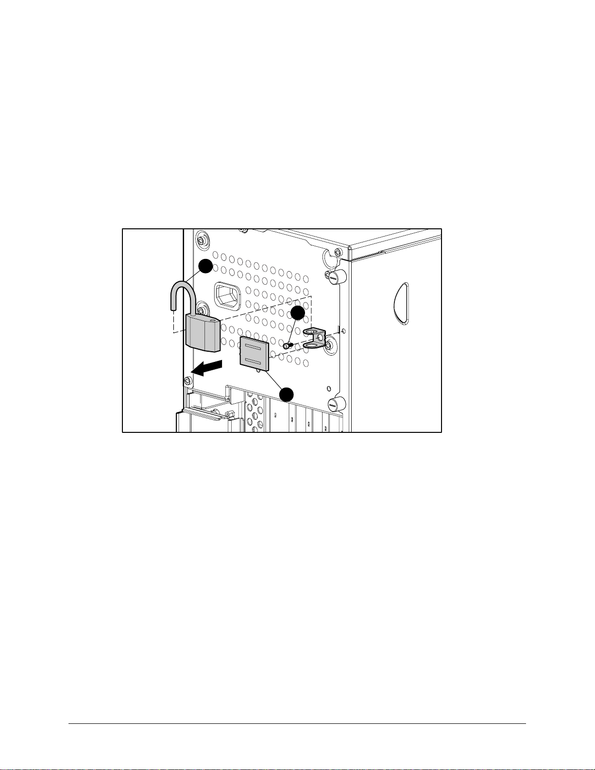
Workstation Feet
NOTE: Not all procedures in this chapter require the removal of the workstation feet. Be sure to
thoroughly read each removal and replacement procedure before attempting to access the
workstation’s internal components.
To remove the workstation fe et:
1. Perform the service preparations shown on page 3-2, then lay the workstation on its side.
2. Remove the screws that secure the feet.
3. Remove the feet.
Figure 3-3. Removing the workstation feet
4. To replace the feet, reverse the above procedure.
IMPORTANT: Compaq recommends that you perform certain removal and replacement
procedures with the workstation laying on its side. Re fer to each procedure for instructions.
Page 25
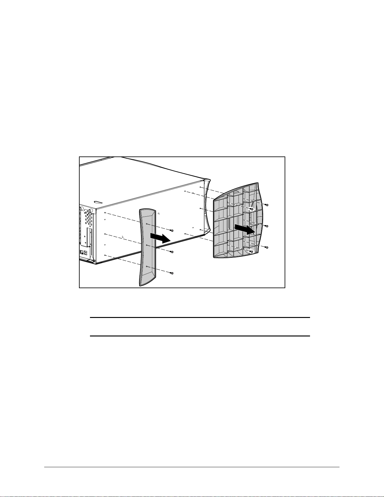
Side Access Panel
To remove the side access panel:
1. Perform the service preparations shown on page 3-2.
2. Loosen the four rear panel thumbscrews, then slide the side access off.
3-5
CAUTION: Do not operate the workstation with the side access panel removed.
The panel is an integral part of the cooling system; removing it while the system is
operating may adversely affect data integrity.
Figure 3-4. Loosening the thumbscrews and removing the side access panel
WARNING: To reduce the risk of personal injury from hot surfaces, allow the
internal system components to cool before touching.
IMPORTANT: When replacing the side access panel, be sure to tighten all four
thumbscrews.
NOTE: The hood label attached to the inside of the side access panel provides system
configurations and the installation of additional components.
To replace the side access panel:
1. Be sure all grounding clips and EMI gaskets (shielding strips) are in place.
2. Slide the side access panel in at an angle on one side, drop it into place, then slide it into
the unit completely.
3. Tighten the rear panel thumbscrews.
Compaq Professional Workstation AP500 Maintenance and Service Guide
Page 26
3-6 Removal and Replacement Procedures
Front Bezel
To remove the front bezel:
1. Perform the service preparations shown on page 3-2.
2. Remove the side access panel.
3. Push the front bezel release latches 1 and remove the bezel 2.
COMPACT
1
2
Figure 3-5. Removing the front bezel
To replace the front bezel:
1. Line up the hinges and release latches with the appropriate slots on the f ront of the
chassis.
2. Press the bezel in to secure the release latches.
Page 27
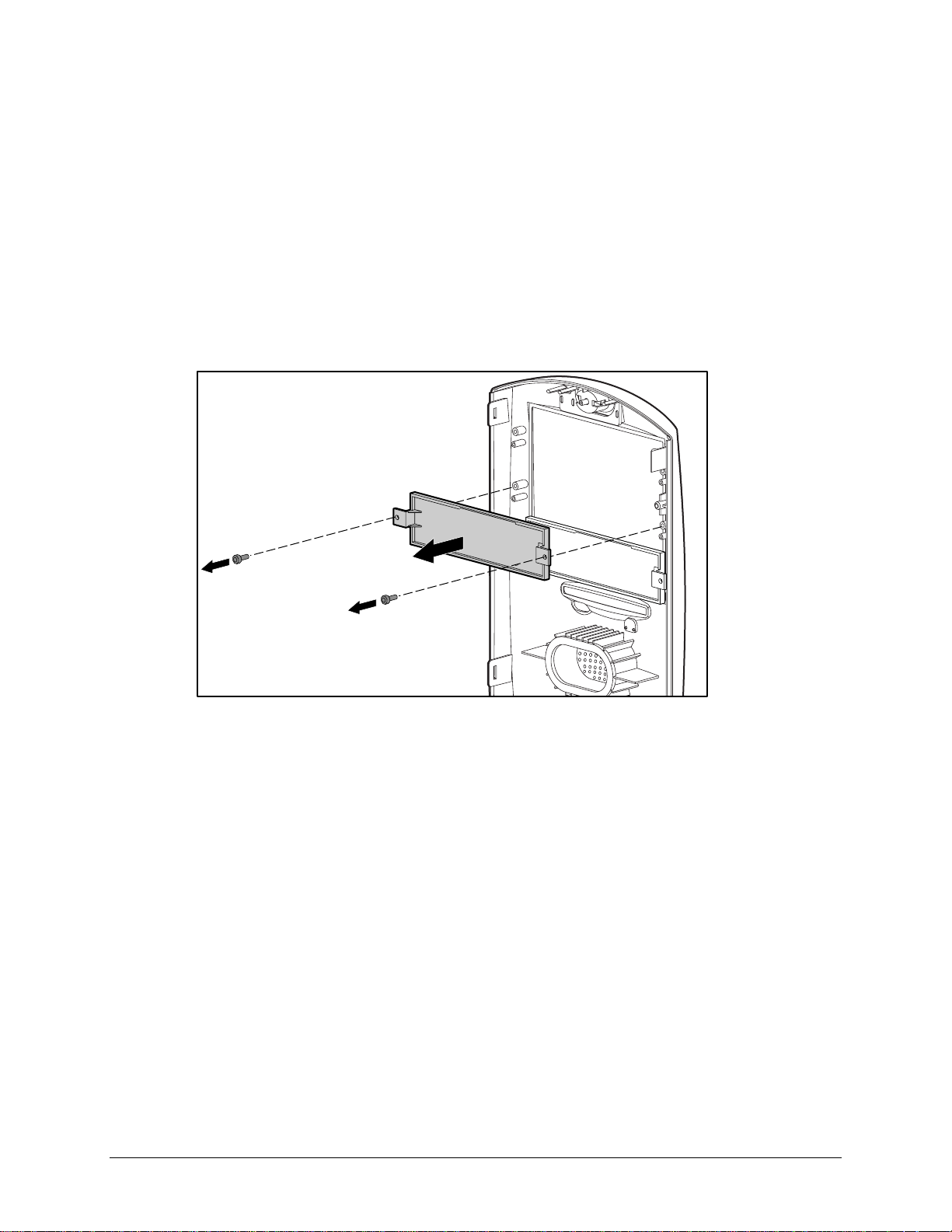
Blank Drive Bezel
To remove a blank drive bezel:
1. Perform the service preparations shown on page 3-2.
2. Remove the following components:
❏ Side access panel
❏ Front bezel
3. Remove the screws that secure the blank drive bezel to the front bezel.
3-7
Figure 3-6. Removing a blank drive bezel
To replace a blank drive bezel, reverse the above procedure.
Compaq Professional Workstation AP500 Maintenance and Service Guide
Page 28
3-8 Removal and Replacement Procedures
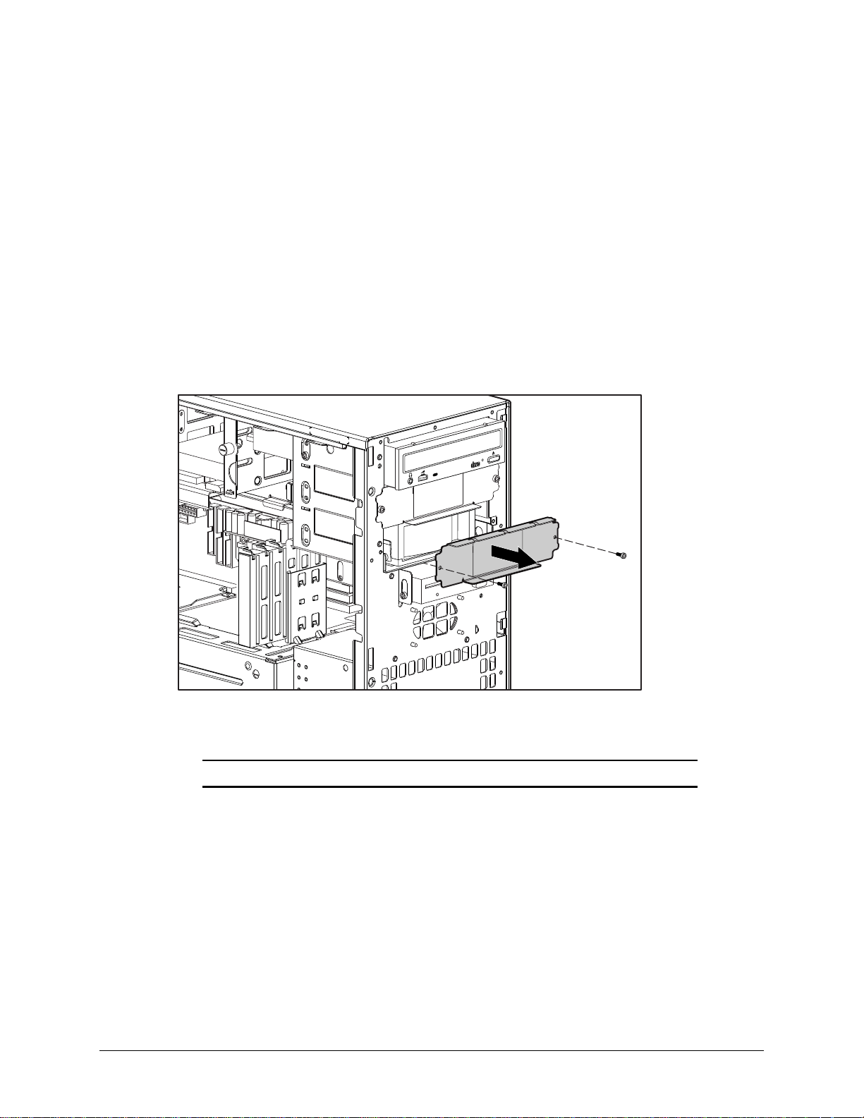
EMI/Cooling Shield
An EMI/cooling shield cover s bays 5 and 6 to provide proper cooling and EMI protection.
To remove an EMI/cooling shield:
1. Perform the service preparations shown on page 3-2.
2. Remove the following components:
❏ Side access panel
❏ Front bezel
3. Remove the two screws that connect the EMI/cooling shield to the drive cage.
4. Remove the EMI/cooling shield from the drive slot.
COMPACT
Figure 3-7. Removing the EMI/cooling shield
To replace the EMI/cooling shield, reverse the above procedure.
IMPORTANT: You must replace the shield after a hard drive is installed in the bay.
Page 29
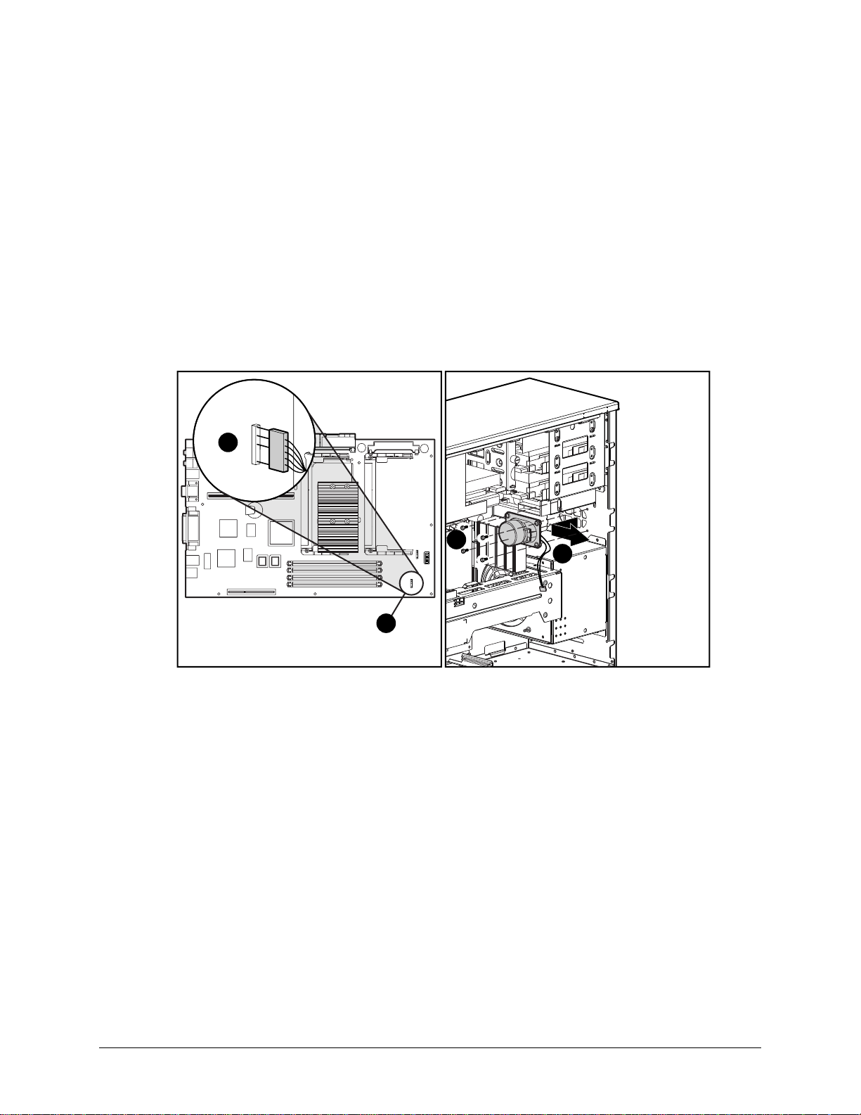
Speaker
3-9
To remove the speaker:
1. Perform the service preparations shown on page 3-2.
2. Remove the side access panel.
3. Unplug the speaker connector from the system board 1, and remove the cable from the
clip.
4. Remove the four T-15 screws securing the front of the speaker to the chassis 2.
5. Remove the speaker fr om the workstation by sliding it back, then lifting it up and out of
the chassis 3.
1
2
1
Figure 3-8. Removing the speaker
To replace the speaker, reverse the above procedure.
3
Compaq Professional Workstation AP500 Maintenance and Service Guide
Page 30

3-10 Removal and Replacement Procedures
I/O Bracket Assembly
The I/O bracket assembly (expansion board assembly) contains a backplane board (also ca lled a
riser card), card guide, and any expansion boa rds. To remove the I/ O bracket assembly:
1. Perform the service preparations shown on page 3-2, then lay the workstation on its side.
2. Remove the following components:
❏ Workstation feet
❏ Side access panel
CAUTION: The power supply in the Compaq Professional Workstation AP500
contains an auxiliary power section. Be sure the power switch is off and the unit is
unplugged before rem oving the I/O bracket assembly in the next step.
3. Grasp the I/O bracket assembly and pull it out of the chassis.
Figure 3-9. Removing the I/O bracket assembly
IMPORTANT: After reconnecting the power cord to the grounded AC outlet and to the
workstation, DO NOT turn the power button on if the Power LED is a steady amber color. A
steady amber color indicates that the I/O bracket assembly is not seated properly.
Disconnect the power cord and reseat the I/O bracket assembly.
Page 31

Replacing the I/O Bracket Assembly
To replace the I/O bracket assembly (expansion board assembly), follow these steps:
1. Grasp the assembly and insert it into the chassis and connector on the system board. Press
firmly on the I/O bracket assembly, where the backplane is connected to the system
board.
2. Connect the power cord to the grounded AC outlet and to the workstation. DO NOT turn
on the power switch.
3. Check if the power LED is a steady amber color. A steady amber color indicates the I/O
bracket assembly, proc essor(s), or termina t or board (if installed) is not seated properly.
4. If the power LED is a steady amber color, disconnect the power cor d from the grounded
AC outlet, reseat the I/O bracket assembly, processor(s), or terminator board (if installed),
then reconnect the power cord.
5. Once the power LED is a steady green color, disconnect the power cord once again before
continuing with additional service.
WARNING: DO NOT turn on the power switch unless the I/O bracket assembly,
processor(s), and terminator board (if installed) are seated properly and the power
LED is a steady green color. To reduce the risk of injury, DO NOT turn on the
power until the workstation is completely reassembled.
3-11
Compaq Professional Workstation AP500 Maintenance and Service Guide
Page 32

3-12 Removal and Replacement Procedures
Expansion Boards
This section discusses removal and replacement procedures for PCI or ISA expansion boards and
the Accelerated Graphics Port (AGP) graphics controller.
NOTE: The following instructions also apply to installing and removing graphics controllers. For
information about the installed graphics controller, refer to the appropriate guide on the
SmartStart for Workstations CD under X:/DOCS/GRAPHICS, where X is the CD-ROM or DVD-ROM
drive on your machine.
Identifying the PCI and ISA Expansion Slots
The Compaq Professional Workstation A P500 contains five expansion slots on the I/O br acket
assembly: three PCI expansion slots, one shared PCI/ISA expansion slot, a nd one ISA expansion
slot. The following illustration identifies the physical locations. See the corresponding table for
component names.
1
Figure 3-10. Identifying the expansion slots
2
3
4
5
Page 33

Table 3-1
PCI/ISA Slots
Reference Description
1 PCI/ISA shared expansion slot*
2 PCI expansion slot
3 PCI expansion slot
4 PCI expansion slot
5 ISA slot
*Cannot be used simultaneously
NOTE: PCI=Peripheral Component Interconnect ISA=Industry Standard Architecture
3-13
Compaq Professional Workstation AP500 Maintenance and Service Guide
Page 34
3-14 Removal and Replacement Procedures
Removing a PCI or ISA Expansion Board
NOTE: The following instructions also apply to installing and removing graphics controllers. For
information about the installed graphics controller, refer to the appropriate guide on the
SmartStart for Workstations CD under X:\DOCS\GRAPHICS, where X is the CD-ROM or DVD-ROM
drive on your machine.
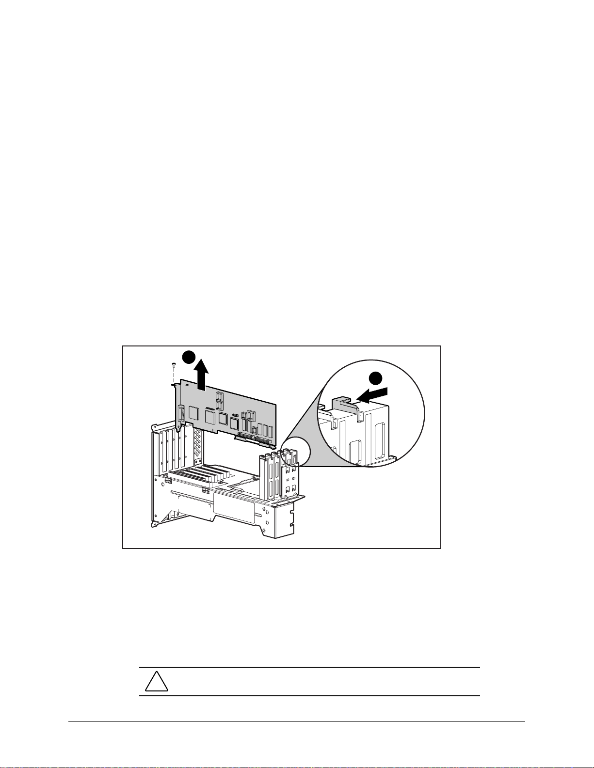
To remove a PCI or ISA expansion board:
1. Perform the service preparations shown on page 3-2, then lay the workstation on its side.
2. Remove the following components:
❏ Workstation feet
❏ Side access panel
❏ I/O bracket assembly
3. Remove the retaining screw that holds the expansion board in place.
4. Move the tab 1 to release the board.
5. Hold the expansion board at each end and carefully rock it back and forth until the
connectors pull free from the slot. Then lift the board from the slot 2.
2
1
Figure 3-11. Removing an expansion board
To install an expansion board:
1. Remove the expansion slot cover.
2. Press firmly on the expansion board so that the whole connector seats properly in the
expansion board slot. If you are installing a full length expansion board, be sure to engage
the card guide.
3. Replace the retaining screw.
CAUTION: If you permanently remove an expansion board, install a protective
slot cover to ensure proper cooling.
Page 35

Removing a Symbios Wide Ultra2 PCI SCSI Controller
NOTE: For best performance, do not mix Wide-Ultra and Wide Ultra2 SCSI hard drives on the
same SCSI cable or the same channel.
To remove a Wide Ultra2 SCSI Controlle r:
1. Perform the service preparations shown on page 3-2, then lay the workstation on its side.
2. Remove the following components:
❏ Workstation feet
❏ Side access panel
3. Remove the I/O bracket assembly.
4. Disconnect the SCSI cable from the controller.
5. Remove the retaining screw that holds the controller in place.
6. Remove the controller.
To replace the controller, reverse the above procedure.
3-15
Compaq Professional Workstation AP500 Maintenance and Service Guide
Page 36

3-16 Removal and Replacement Procedures
Removing the Accelerated Graphics Port (AGP) Graphics
Controller
The Compaq Professional Workstation A P500 comes equipped with an AGP expansion slot on
the system board. The following illustration identifies the physical location of the AGP graphics
controller expansion slot.
NOTE: For information about the installed graphics controller, refer to the appropriate guide on
the SmartStart for Workstations CD under X:\DOCS\GRAPHICS, where X is the CD-ROM or DVDROM drive designation.
To remove the AGP graphics controller:
1. Remove the retaining screw that holds the controller in place.
2. Hold the controller at each end, then pull up.
Figure 3-12. Removing an AGP graphics controller
To replace the controller, reverse the above procedure.
CAUTION: If you permanently remove an AGP graphics controller, install a
protective slot cover to ensure proper cooling.
IMPORTANT: When replacing the AGP graphics controller, be sure to use AGP graphics
controllers with ATX format brackets. This will ensure the controller fits properly.
IMPORTANT: When you install an AGP graphics controller, be sure to press firmly on the
controller so that the whole connector seats properly in the AGP expansion slot.
Page 37

Removing the Card Guide
To remove the card guide:
1. Perform the service preparations shown on page 3-2, then lay the workstation on its side.
2. Remove the following components:
❏ Workstation feet
❏ Side access panel
❏ I/O bracket assembly
❏ Full-length expansion boards, if installed
3. Using a blunt tool, press inward on the two c enter tabs on the card guide.
4. Gently pull the card guide out.
3-17
Figure 3-13. Removing the card guide
To replace the card guide, reverse the above procedure.
IMPORTANT: Before replacing the I/O bracket assembly, read “Important Guidelines for I/O
Bracket Assembly Replacement” earlier in this chapter.
Compaq Professional Workstation AP500 Maintenance and Service Guide
Page 38

3-18 Removal and Replacement Procedures
Removing the Backplane Board
The backplane board (also called the riser card) is attached to the I/O bracket assembly. The
backplane board contains the expansion slots described and shown in the “ Expansion Boards”
section in this chapter.
To remove the backpla ne board:
1. Perform the service preparations shown on page 3-2, then lay the workstation on its side.
2. Remove the following components:
❏ Workstation feet
❏ Side access panel
❏ I/O bracket assembly
❏ Expansion boards (if installed)
❏ Graphics controller (if installed)
3. Remove the four screws that secure the backplane board to the I/O bracket assembly.
4. Slide out then remove the backplane board from the I/O bracket assembly.
Figure 3-14. Removing the backplane board
To replace the backplane board, reverse the above procedure.
IMPORTANT: Before replacing the I/O bracket assembly, read “Important Guidelines for
I/O Bracket Assembly Replacement” earlier in this chapter.
NOTE: When replacing the backplane board, align the top edge of the board with the slots in the
I/O bracket assembly.
Page 39

System Fan
To remove the system fan:
1. Perform the service preparations shown on page 3-2, then lay the workstation on its side.
2. Remove the following components:
3. Disconnect the fan cable from the system board 1.
4. Remove the two screws at the top of the fan 2, then pull back and slide up 3.
3-19
❏ Workstation feet
❏ Side access panel
NOTE: If the system board has not been removed, slide it out a few inches before removing the
system fan.
1
Figure 3-15. Removing the system fan
2
3
2
Compaq Professional Workstation AP500 Maintenance and Service Guide
Page 40

3-20 Removal and Replacement Procedures
5. Pull the rubber isolators through the br acket 1, then remove the fan from the bracket 2.
Figure 3-16. Removing the fan from the bracket
1
2
To replace the system fan, reverse the above procedure.
Page 41

Mass Storage Devices
This section discusses removal and replacement procedures for the mass storage devices
supported on the Compaq Professional Wor ksta tion AP500.
Drive Positions
The Compaq Professional Workstation A P500 can house up to seven mass storage devic es. All
models ship with a CD-ROM drive installed in Bay 4 and a diskette drive installed in Bay 7. The
following illustration identifies the physical drive loca tions. See the corresponding table for a
description of the drive bay components.
3-21
COMPACT
Figure 3-17. Identifying drive positions
4
5
6
7
2
3
3
2
4
1
Compaq Professional Workstation AP500 Maintenance and Service Guide
Page 42

3-22 Removal and Replacement Procedures
Reference Component Description
1 Bay 1 Part of the removable hard drive cage. A 3.5-inch, third-height bay that supports a
2 Bay 2 Part of the removable hard drive cage. A 3.5-inch, third-height bay that supports a
3 Bay 3 Part of the removable hard drive cage. A 3.5-inch, third-height bay that supports a
4 Bay 4 A CD-ROM drive is shipped in Bay 4.
5 Bay 5* 5.25-inch, half-height bay that supports 1.0-inch or 1.6-inch storage devices. An
6 Bay 6* 5.25-inch, half-height bay that supports 1.0-inch or 1.6-inch storage devices. An
Table 3-2
Drive Positions
1.0-inch hard drive or a 1.6-inch hard drive.
1.0-inch hard drive. Bay 2 is not available when a 1.6-inch hard drive is installed in
Bay 1 or Bay 3.
1.0-inch hard drive or a 1.6-inch hard drive.
optional hard drive, diskette drive, CD-ROM drive, DVD-ROM drive, or tape drive can
be installed in Bay 5.
optional hard drive, diskette drive, CD-ROM drive, DVD-ROM drive, or tape drive can
be installed in Bay 6.
7 Bay 7 3.5-inch, third-height bay that supports a 1.0-inch device. A standard 3.5-inch
diskette drive is shipped in Bay 7.
* An additional Zip drive can be installed in these bays.
CAUTION: If a hard drive is installed in Bay 5 or 6 or if the bays are empty, be
sure that EMI/cooling shields are installed to ensure proper air flow and cooling.
IMPORTANT: Compaq recommends 10,000 rpm hard drives be installed first in Bays 1, 2,
or 3. Installing a 10,000 rpm hard drive in Bays 5 or 6 will require an additional cooling fan
kit.
Page 43

Hardware Screws
A total of 17 extra hardware screws are provided on the side of the air plenum. The top group of
eight screws 1 is for installing hard dr ives in the removable hard drive cage. The bottom group
of nine screws 2 is for installing removable media storage devices in the front drive bays.
3-23
1
2
Figure 3-18. Locating the hardware screws
Compaq Professional Workstation AP500 Maintenance and Service Guide
Page 44

3-24 Removal and Replacement Procedures
CD-ROM Drive or DVD-ROM Drive
To remove the CD-ROM drive or DVD-ROM drive:
1. Perform the service preparations shown on page 3-2.
2. Remove the following components:
❏ Side access panel
❏ Front bezel
3. Remove the retaining screws 1 and slide the drive 2 halfway out.
4. Disconnect the audio, data, and power cables 3 from the back of the drive.
1
COMPACT
2
3
Figure 3-19. Disconnecting the cables from the back of the CD-ROM drive or DVD-ROM drive
Page 45
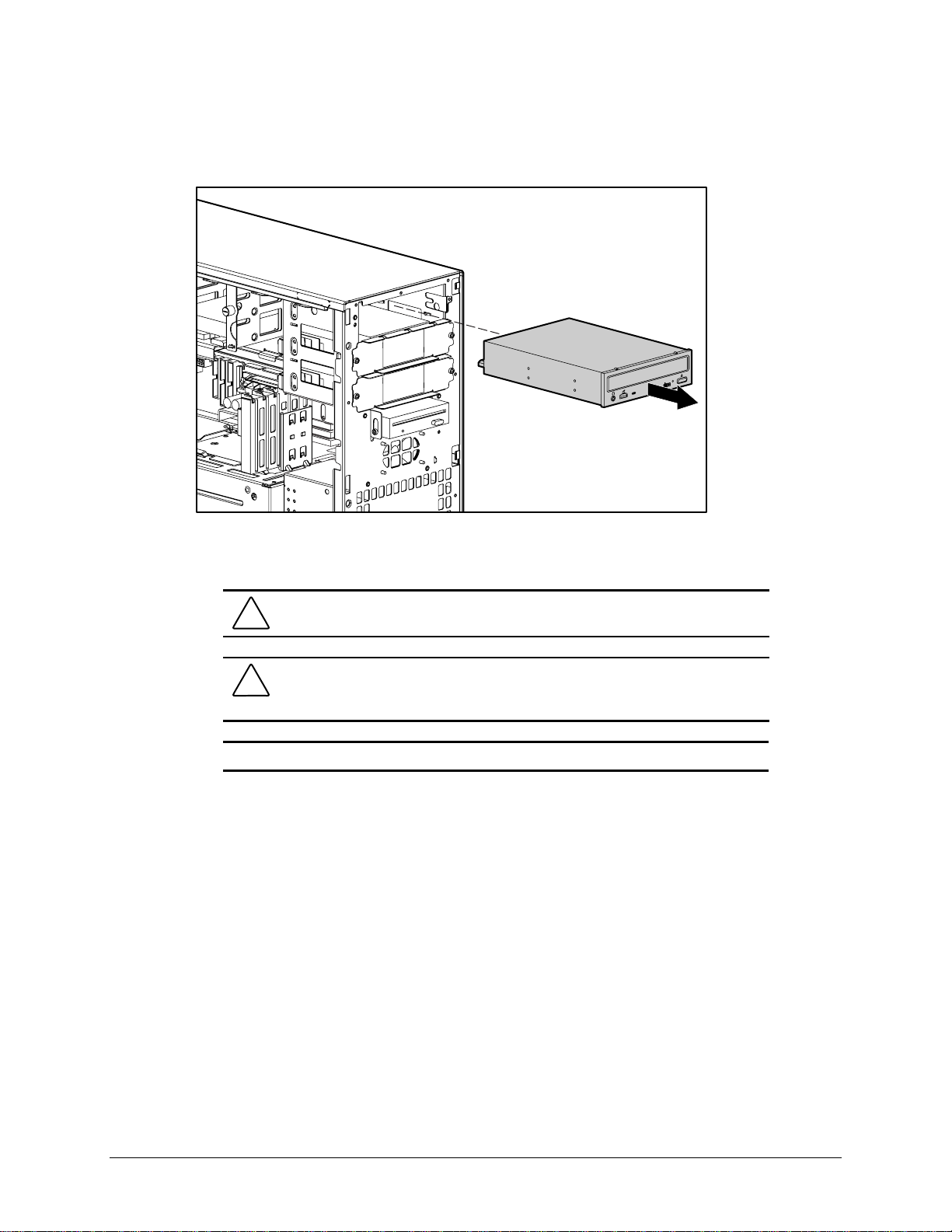
5. Pull the drive completely out of the drive cage.
Figure 3-20. Removing the CD-ROM drive or DVD-ROM drive
3-25
COMPACT
To replace the drive, reverse the above procedure.
CAUTION: Use only 3/16-inch or 5 mm long screws. Using longer screws can
damage the internal components of the drive.
CAUTION: When servicing the workstation, be sure cables are placed in their
proper locations during the reassembly process. Improper cable placement can
damage the computer.
IMPORTANT: Make sure you attach the middle connector of the data cable to the drive.
NOTE: Be sure to transfer the guide screw from the old drive to the new one. The screw is
installed on the right front side of the drive. Note that extra guide screws are provided on the side
of the air plenum.
Compaq Professional Workstation AP500 Maintenance and Service Guide
Page 46

3-26 Removal and Replacement Procedures
Diskette Drive
IMPORTANT: Before removing the diskette drive, be sure there is no diskette in the drive.
To remove the diskette drive:
1. Perform the service preparations shown on page 3-2.
2. Remove the following components:
❏ Side access panel
❏ Front bezel
3. Disconnect the cables from the back of the diskette drive.
Figure 3-21. Disconnecting the cables from the back of the diskette drive
4. Remove the diskette drive retaining screws.
Page 47

5. Pull the diskette drive straight out.
COMPACT
Figure 3-22. Removing the diskette drive
3-27
To replace the diskette drive, reverse the above procedure.
CAUTION: Use only 3/16-inch or 5 mm long screws. Using longer screws can
damage the internal components of the drive.
CAUTION: When servicing the workstation, be sure cables are placed in their
proper locations during the reassembly process. Improper cable placement can
damage the computer.
NOTE: Be sure to transfer the guide screw from the old drive to the new one. The screw is
installed on the right front side of the drive. Note that extra guide screws are provided on the side
of the air plenum.
Compaq Professional Workstation AP500 Maintenance and Service Guide
Page 48

3-28 Removal and Replacement Procedures
Removing a 7200 rpm Hard Drive from Bays 5 or 6
Drive bays 5 and 6 can be configured with either a 1.0- inch or a 1.6-inch, 7200 rpm hard drive.
Other than using different sc rew holes, the removal of both drives a basically the same.
To remove a 7200 rpm hard drive:
1. Perform the service preparations shown on page 3-2.
2. Remove the following components:
❏ Side access panel
❏ Front bezel
3. Disconnect the signal and power cables.
Figure 3-23. Disconnecting the cables from the hard drive
Page 49

4. Remove the EMI/cooling shield.
Figure 3-24. Removing the EMI/cooling shield
5. Pull the hard drive straight out.
3-29
COMPACT
Figure 3-25. Removing the hard drive
COMPACT
Compaq Professional Workstation AP500 Maintenance and Service Guide
Page 50

3-30 Removal and Replacement Procedures
6. Remove the retaining screws and lift the hard drive from the bracket.
Figure 3-26. Removing a hard drive from the hard drive bracket
To reinsert a hard drive in Bays 5 or 6, revers e the above procedure.
CAUTION: Use only 3/16-inch or 5 mm long screws. Using longer screws can
damage the internal components of the drive.
CAUTION: When servicing the workstation, be sure cables are placed in their
proper locations during the reassembly process. Improper cable placement can
damage the computer.
Page 51

Removing a 10,000-rpm Hard Drive from Bays 5 or 6
Drive bays 5 and 6 can be configured with a 10,000 rpm hard drive. The remova l of the drive is
basically the same as removing a 7200 rpm hard drive except you will be also be removing a
cooling fan. :
To remove a 10,000-rpm hard drive:
1. Perform the service preparations shown on page 3-2.
2. Remove the following components:
❏ Side access panel
❏ Front bezel
3. Disconnect the signal and power cables.
3-31
Figure 3-27. Disconnecting the cables from the hard drive
Compaq Professional Workstation AP500 Maintenance and Service Guide
Page 52

3-32 Removal and Replacement Procedures
4. Disconnect the fan power cable.
Figure 3-28. Disconnecting the fan power cable
5. Remove the retaining scre w s securing the fan.
NOTE: The screws that secure the fan also secure the hard drive.
Figure 3-29. Removing the fan
Page 53

6. Remove the EMI/cooling shield.
Figure 3-30. Removing the EMI/cooling shield
7. Pull the hard drive straight out.
3-33
COMPACT
Figure 3-31. Removing the hard drive
COMPACT
Compaq Professional Workstation AP500 Maintenance and Service Guide
Page 54

3-34 Removal and Replacement Procedures
8. Remove the retaining screws and lift the hard drive from the bracket.
Figure 3-32. Removing a hard drive from the hard drive bracket
To reinstall a hard drive in Bays 5 or 6, reverse the above procedure.
CAUTION: Use only 3/16-inch or 5 mm long screws. Using longer screws can
damage the internal components of the drive.
CAUTION: When servicing the workstation, be sure cables are placed in their
proper locations during the reassembly process. Improper cable placement can
damage the computer.
Page 55

Removing the Fan from a Hard Drive Installed in
Bays 5 or 6
NOTE: This section only applies if there is a fan installed over Bays 5 and 6. The fan is required
only in high-altitude environments or when a hard drive faster than 7200 rpm is installed in Bay 5
or 6.
To remove the fan:
1. Perform the service preparations shown on page 3-2.
2. Remove the side access panel.
3. Disconnect the power cable.
3-35
Figure 3-33. Disconnecting the power cable
Compaq Professional Workstation AP500 Maintenance and Service Guide
Page 56

3-36 Removal and Replacement Procedures
4. Remove the screws that hold the fan in place and remove the fan.
NOTE: The screws also secure the hard drive in that bay and must be replaced. DO NOT
remove the screws from the CD-ROM drive. They are not used to install the fan.
Figure 3-34. Removing the fan
To replace the fan, reverse the above procedure.
Page 57

Removing a Hard Drive from the Removable Hard Drive
Cage
The removable hard drive cage supports up to three 1.0-inch hard drives or two 1.6-inch hard
drives. Other than using different screw holes, the removal and replacement for both drives is
basically the same.
To remove a hard drive in the removable har d drive cage:
1. Perform the service preparations shown on page 3-2, then lay the workstation on its side.
2. Remove the following components:
❏ Workstation feet
❏ Side access panel
3. Disconnect the cables from the back of the hard drive(s).
3-37
Figure 3-35. Disconnecting the cables from the back of a hard drive
Compaq Professional Workstation AP500 Maintenance and Service Guide
Page 58

3-38 Removal and Replacement Procedures
4. Pull back the power supply air baffle 1.
5. Loosen the two thumbscrews 2 and slide the removable hard drive cage out 3.
1
2
3
Figure 3-36. Removing the removable hard drive cage
6. Remove the four screws that secure the hard drive to the removable hard drive cage and
pull the hard drive straight out.
Figure 3-37. Removing a hard drive
CAUTION: When servicing the workstation, make sure cables are placed in their
proper locations during the reassembly process. Improper cable placement can
damage the workstation.
Page 59

Installing a Hard Drive in the Removable Hard Drive Cage
To install a hard drive in the removable hard drive cage:
1. Perform the service preparations shown on page 3-2, then lay the workstation on its side.
2. Remove the following components:
❏ Workstation feet
❏ Side access panel
❏ Removable hard drive c age
3. Remove the hard drive sc rews (top group of screws) from the side of the air plenum
located at the front of the workstation.
3-39
4
3
2
1
Figure 3-38. Locating the removable hard drive screw holes
Table 3-3
Removable Hard Drive Screw Holes
Reference Bay
4 Bay 3: 1.0-inch drive
3 Bay 3: 1.6-inch drive
2 Bay 2: 1.0-inch drive
1 Bay 1: 1.0-inch drive
4. Insert the hard drive into the removable hard drive cage, and secure the drive with the four
hard drive screws. (Se e the above illustration and table for the location of the correct screw
holes for the hard drive you ar e installing.)
Compaq Professional Workstation AP500 Maintenance and Service Guide
Page 60

3-40 Removal and Replacement Procedures
Figure 3-39. Inserting a hard drive in the removable hard drive cage
4
2
1
Figure 3-40. Reinstalling a removable hard drive cage
5. Pull back the air baffle 1.
6. Slide the hard drive cage 2 into place.
7. Align the tabs 3 on the bottom of the cage with the workstation chassis.
8. Tighten the thumbscrews 4.
9. Connect the signal and power cable s to the hard drive.
10. Reassemble the workstation.
3
Page 61
SCSI Cables and Guidelines
All workstation models use three areas for connecting mass storage SCSI devices: internally
with hard drive in the removable hard drive cage, internally with storage devices in the front
panel drive bays, and externa lly w ith external storage devices. The workstation has an integrated
Wide-Ultra SCSI controller that has one internal connector on the system board and one external
connector on the rear panel.
SCSI Cables
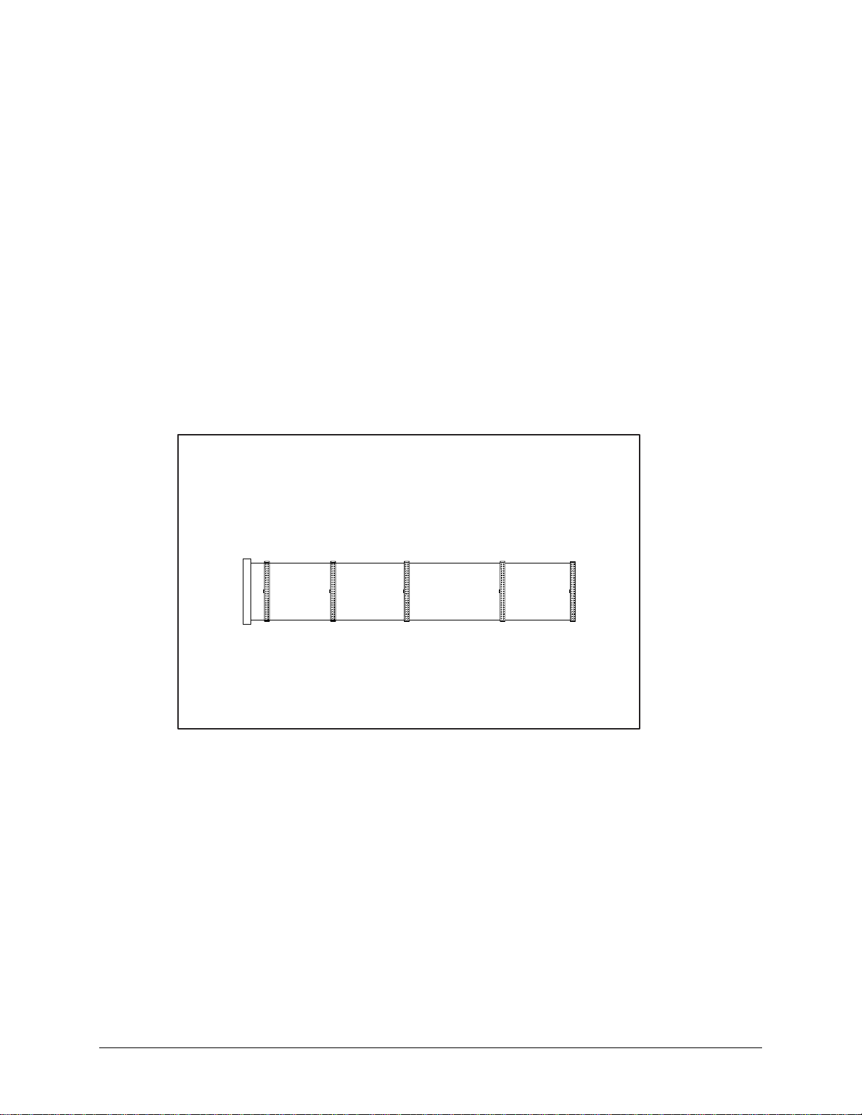
The workstation ships standard with a 5-de vice Wide-Ultra or Wide Ultra2 SCSI cable that has a
terminator on one end. The other end of this cable connects to the internal Wide-Ultra SCSI
connector on the system board. The first device connector of the cable connects to the hard drive
in the removable hard drive cage. The cable has five connectors to handle up to five SCSI
devices, a maximum of three in the rem ovable hard drive cage and two in the front drive bay
area.
3-41
Figure 3-41. 5-device Wide-Ultra SCSI cable
NOTE: The SCSI cable included with the workstation may look slightly different than the one
pictured.
When installing a Wide Ultra2 SCSI hard drive a Wide U ltra2 SCSI cable (not shown) is
required.
Compaq Professional Workstation AP500 Maintenance and Service Guide
Page 62

3-42 Removal and Replacement Procedures
SCSI Guidelines for Installing SCSI Devices
■ If you are installing a narrow SCSI device, you will need to attach a 68- to 50-pin SCSI
adapter to the narrow SCSI device.
■ A maximum of seven SCSI devices may be installed on the integrated Wide-Ultra SCSI
controller.
■ A unique SCSI ID (0-6 and 8-15) must be set for each SCSI device installed.
■ Before you install a SCSI device, verify the SCSI ID of the drive, and if necessary, set the
SCSI ID to a unique ID number.
■ The controller identifies a SCSI device by its SCSI ID (SCSI ID 1) number rather than its
bay location (Bay 2). The refore, moving a SCSI device from one bay loca tion to another
or changing the position of the device on the SCSI chain does not affect the
communication between the c ontroller and the SCSI device.
■ The reserved and available SCSI ID numbers for SCSI devices are as follows:
❏ SCSI ID 0 is reserved for the primary hard drive (boota ble drive).
❏ SCSI ID 7 is reserved for the controller.
❏ SCSI IDs 1-6 and 8-15 are available. Do not use IDs 8-15 for narrow devices on the
same SCSI bus.
■ Bay 4 is reserved for the CD-ROM drive. Do not install a SCSI device in this bay.
■ If only one SCSI hard drive is used, it should be installed on the lowest numbered bay
(Bay 1).
■ Every SCSI chain must be ter minated (closed) at both ends.
■ SCSI devices may not have ter minating jumpers on the device. Determine if the device
ought to have termination enabled or disabled. Set the termination if necessary.
Termination on these device s must be achieved with a non-terminated cable.
■ Turn on an external SCSI device before turning on power to the workstation. This enables
the system board controller to r ecognize the external SCSI devic e.
■ When an external SCSI device is connected to the external SCSI connector on the rear
panel of the workstation, that devic e becomes the end of the SCSI cha i n and must be
terminated.
■ SCSI drives on the SCSI controller must be either internal or in an external storage
system, but not both.
SCSI Guidelines for Optimizing Performance
■ To maintain Ultra speeds, do not insta ll more than four SCSI devices on a SCSI bus.
■ Do not mix Wide-Ultra and nar row SCSI devices on the same SCSI chain or the same
controller.
For additional information about optional SCSI devices, refer to the doc umentation included
with the device.
Page 63

System Board Assembly
The system board assembly contains the DIMMs, Pentium II or Pentium III processor/heat sink,
Processor Power Module( s), system board with tray, the AGP Graphics Controller, and the
external battery, if installed. Each of these components is spa red separately. The com ponents on
the system board are illustra ted in Figure 3-43. See Table 3-4 for component names.
CAUTION: Static electricity can damage the electronic components of the
workstation. Before beginning these procedures, make sure you are properly
grounded. See “Electrostatic Discharge Information” in Chapter 2.
System Board with Tray and Cage
To remove the system board with tray and cage:
1. Perform the service preparations shown on page 3-2, then lay the workstation on its side.
2. Remove the following components:
❏ Workstation feet
❏ Side access panel
3-43
❏ I/O bracket assembly
3. Disconnect and remove all cables plugged into the system board.
IMPORTANT: Be sure to disconnect the system fan and speaker connectors located at the
front of the system board before removing the system board with tray and cage.
4. Grasp the back edge of the system board with tray and slide it out of the chassis.
Figure 3-42. Removing the system board with tray and cage
Compaq Professional Workstation AP500 Maintenance and Service Guide
Page 64

3-44 Removal and Replacement Procedures
To install a new system board with tray and cage:
1. Remove the following components f rom the system board with tray:
❏ DIMMs
❏ Processor(s)
❏ Processor power module( s)
❏ External battery (if installed)
2. Install the components on the new system board with tr ay. Before reinstalling the
DIMMs, see “Important Guidelines for DIMM Installation” earlier in this chapter.
3. Slide the new system board with tray into the chassis.
4. Connect all cables to the system board.
5. Replace the I/O bracket assembly, the side access panel, and the workstation feet.
Page 65

System Board Components
1 2 3 4 5 6 7 8 9
3-45
10
18
17
16
Figure 3-43. Identifying system board components
System Board Components
Reference Component
1
2
3
4
5
6
7
8
9
:
;
<
=
>
?
@
A
B
Power Switch Connector and LED Header
Power Connector
External Battery Jumper
Diskette Drive Connector
Secondary IDE Connector
Primary IDE Connector
SCSI Connector
Primary Processor Power Module
Secondary Processor Power Module Slot
Secondary Processor Slot
Primary Processor
Fan Headers
SW1 Switch
Speaker Header
DIMM Sockets 1- 4
AGP Graphics Controller Connector
Wake-On-LAN Connector
Expansion Board Connector
11
12
13
14
15
Table 3-4
Compaq Professional Workstation AP500 Maintenance and Service Guide
Page 66

3-46 Removal and Replacement Procedures
Dual Inline Memory Modules (DIMMs)
The Compaq Professional Workstation A P500 has four DIMM slots on the system board to
support up to a maximum of 1 GB. See the following illustration for the physical loc ation of the
DIMM sockets.
DIMM 4
DIMM 3
DIMM 2
DIMM 1
Figure 3-44. Overview of DIMM sockets
NOTE: DIMMs do not need to be installed in pairs, and can be installed in any of the available
DIMM sockets. The DIMM sockets are numbered in sequence from 1-4. DIMM 1 is located closest
to the processor, and DIMM 4 is located closest to the edge of the system board.
Important Guidelines for DIMM Installation
When installing DIMMs, you MUST follow these guidelines:
■ Use only 32-, 64-, 128-, 256-MB Registered 100-MHz Error Checking and Correcting
(ECC) SDRAM DIMMs.
■ DIMMs must have a 4-KHz refresh rate.
■ DO NOT INSTALL DIMMS THAT DO NOT SUPPORT ERROR CHECKING
AND CORRECTING (ECC).
■ A DIMM can be installed one way only. Be sure to match the two key slots on the DI MM
with the tab on the DIMM socket. Push the DIMM down into the DIMM socket, ensuring
that it is fully inserted and properly seated.
■ When upgrading, do not exceed 1 GB total. Upgrades exceeding 1 GB will cause the
system to halt.
Page 67

Removing a DIMM
To remove a DIMM:
1. Perform the service preparations shown on page 3-2, then lay the workstation on its side.
2. Remove the following components:
❏ Workstation feet
❏ Side access panel
❏ AGP graphics controller, if nec essary
3. Press outward on both latches of the D IMM at the same time 1. This releases the module
and pushes it partially out of the socket.
3-47
CAUTION: When handling a DIMM, be careful not to to uch any of the contacts.
Doing so may damage the DIMM.
CAUTION: Static electricity can damage the electronic components of the
workstation or optional boards. Before beginning these procedures, ensure that
you are properly grounded. See “Electrostatic Discharge Information” in Chapter 2.
4. Lift the module from the socket 2.
1
2
Figure 3-45. Removing a DIMM
To replace a DIMM, reverse the above procedure.
1
Compaq Professional Workstation AP500 Maintenance and Service Guide
Page 68
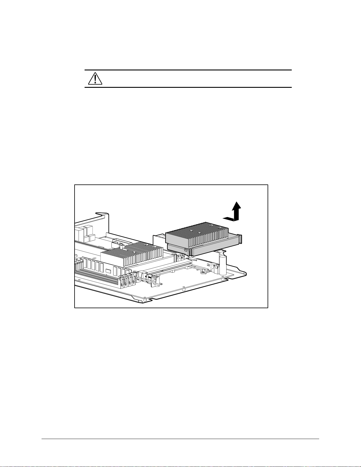
3-48 Removal and Replacement Procedures
Processor and Heatsink Assembly
WARNING: To reduce the risk of personal injury from hot surfaces, allow the
internal system components to cool before touching.
To remove the processor and heatsink assembly:
1. Perform the service preparations shown on page 3-2, then lay the workstation on its side.
2. Remove the following components:
❏ Workstation feet
❏ Side access panel
❏ I/O bracket assembly
3. Push in the latches on each side of the processor until there are two clicks. This locks the
tabs in the open position. Then slide out the processor.
Figure 3-46. Removing the processor and heatsink assembly
To replace the processor and heatsink, reverse the above procedure.
NOTE: Install the primary processor/heatsink assembly in the primary processor slot.
Appearance may vary depending upon the pr ocessor.
When replacing the processor, push the processor tabs outward. The tabs will click twice,
locking the processor to the system board.
Page 69

Processor Power Module
CAUTION: Static electricity can damage the electronic components of the
workstation. Before beginning these procedures, make sure you are properly
grounded. See “Electrostatic Discharge Information” in Chapter 2.
The processor power module (voltage regulator module) is located on the system board.
To remove the processor power module:
1. Perform the service preparations shown on page 3-2, then lay the workstation on its side.
2. Remove the following components:
❏ Workstation feet
❏ Side access panel
❏ I/O bracket assembly
WARNING: To reduce the risk of personal injury from hot surfaces, allow the
internal system components to cool before touching.
3. Press outward on both latches of the processor power module at the same time 1, then lift
the module from the system board 2.
3-49
1
2
Figure 3-47. Removing the processor power module
To replace the processor power module, reverse the above procedure.
Compaq Professional Workstation AP500 Maintenance and Service Guide
Page 70

3-50 Removal and Replacement Procedures
Primary Processor Power Module Cable Insulator
A cable insulator reduces da mage to cables routed over the pow er module. If you are replacing
the primary processor module, you must first remove the cable insulator from the module and
place it on the new power processor module.
To remove the cable insulator:
1. Perform the service preparations shown on page 3-2, then lay the workstation on its side.
2. Remove the following components:
❏ Workstation feet
❏ Side access panel
❏ I/O bracket assembly
❏ Primary power proce ssor module
WARNING: To reduce the risk of personal injury from hot surfaces, allow the
internal system components to cool before touching.
3. Remove the cable insulator from the primary processor power module.
Figure 3-48. Removing the cable insulator
To reinstall the cable insulator, reverse the above procedure.
NOTE: Make sure you firmly press the primary processor power module and cable insulator into
the primary power module connector. Then, secure the two latches on the connector.
Page 71

External Battery
The real-time clock battery that came with the workstation is permanently installed on the
system board. If the original battery becomes inoperative, you must install a replacement battery.
Before attempting to install the replacement battery, read the following section.
Running Computer Setup
Computer Setup automatically detects and configures most Compaq c omponents, including
Compaq hard drives. If the workstation has a Compaq hard drive you do not need to run
Computer Setup prior to installing the replacement battery. However, if the workstation has a
third-party hard drive , you MUST complete the following steps before installing the replacement
battery:
1. Run Computer Setup and record the drive type displayed in the System Configura tion
Summary.
2. If the drive type number is 65 or 66, record the drive parameters.
Drives with these designators are user-defined types, also called soft-drive types.
Whenever the nonvolatile memory (CMOS) has be come invalid, such as after the
installation of a new battery, drive parameters must be entered manually for these userdefined drives.
3-51
After you have completed the battery installation, run Computer Se tup and use the drive table
parameters recorded earlier to reconfigure the system.
WARNING: The system board contains a clock/CMOS lithium battery. The lithium
battery may explode if mistreated. The battery is soldered in and may not be
removed. Do not abuse or disassemble. Use only replacement batteries supplied
by Compaq Computer Corporation.
IMPORTANT: Make a set of backup diagnostics diskettes before installing a new battery.
NOTE: Drive parameters must be reentered after battery installation in order to reconfigure the
hard drive. The hard drive is inoperable until the parameters are reentered.
Compaq Professional Workstation AP500 Maintenance and Service Guide
Page 72

3-52 Removal and Replacement Procedures
Installing the Battery
CAUTION: Static electricity can damage the electronic components of the
workstation. Before beginning these procedures, make sure you are properly
grounded. See “Electrostatic Discharge Information” in Chapter 2 for more
information.
To install an external real-time clock battery:
1. Perform the service preparations shown on page 3-2, then lay the workstation on its side.
2. Remove the following components:
❏ Workstation feet
❏ Side access panel
❏ I/O bracket assembly
3. Remove the backing from the adhesive on the hook-and-loop f astener strip and attach the
battery near the J5 jumper.
4. Connect the battery connec t or to pins 1 - 4 on J5 1 and move the jumper from pins 6 and
7 to pins 5 and 6 2.
Figure 3-49. Installing the replacement battery
2
1
1
1
Page 73

5. Replace the I/O bracket assembly and the side access panel.
6. Place the sticker included with your battery kit on the back of the workstation above the
power connector.
7. Plug in the workstation and reconnect a ny external devices.
WARNING: This equipment is designed for connection to a grounded (earthed)
outlet. The grounding type plug is an important safety feature. To avoid the risk of
electrical shock or damage to the equipment, do not disable this feature.
8. Turn on the workstation.
9. Run computer setup to reconfigur e the system.
■ If the workstation has a Compaq hard drive, you have now successfully completed the
installation.
■ If the workstation has a thir d-party hard drive, you must reconfigure the har d drive using
the parameters recorded earlier.
3-53
Compaq Professional Workstation AP500 Maintenance and Service Guide
Page 74

3-54 Removal and Replacement Procedures
Power Switch Cable Assembly
The power switch cable assembly can be replaced without removing the power supply. To
remove the power switch cable assembly:
1. Perform the service preparations shown on page 3-2.
2. Remove the following components:
❏ Side access panel
❏ Front bezel
❏ CD-ROM drive or DVD-ROM drive (if installed)
3. Disconnect the power switch cable from the system board.
4. Remove the screws that keep the power switch cable assembly in place.
5. Remove the crown from the power switch cable assem bly.
6. Gently slide the cable through the CD-ROM drive bay opening.
7. Remove the power switch cable assembly from the chassis.
Figure 3-50. Removing the power switch cable assembly
To replace the power switch cable assembly, reverse the above procedure.
Page 75

Power Supply
To remove the power supply:
1. Perform the service preparations shown on page 3-2, then lay the workstation on its side.
3-55
WARNING: This procedure should be performed only by qualified personnel. Do
not reconnect power to the computer until the computer cover is replaced.
Connecting the power before replacing the computer cover can result in personal
injury or equipm ent damage.
WARNING: To reduce the risk of electric shock or damage to the equipment:
■ If the system has multiple power supplies, disconnect power from
the system by unplugging all power cords from the power
supplies.
■ Do not disable the power cord grounding plug. The ground plug is
an important safety feature.
■ Plug the power cord into a grounded (earthed) electrical outlet that
is easily accessible at all times.
2. Remove the following components:
❏ Workstation feet
❏ Side access panel
❏ I/O bracket assembly
❏ Power supply air baffle
3. Disconnect all power cables.
NOTE: To facilitate reassembly, note the orientation of each cable connector and the routing of
each cable before you remove it.
Compaq Professional Workstation AP500 Maintenance and Service Guide
Page 76
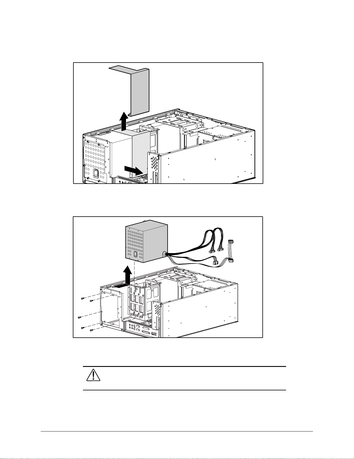
3-56 Removal and Replacement Procedures
4. Remove the power supply air baffle from its position.
Figure 3-51. Removing the power supply air baffle
5. Remove the three scre w s that secure the power supply to the bac k of the chassis.
6. Slide the power supply toward the front of the chassis and pull up to remove it.
Figure 3-52. Removing the power supply
To replace the power supply, reverse the above procedure.
WARNING: Do not reconnect powe r to the computer until to computer cover is
replaced. Connecting the power before replacing the computer cover can result in
personal injur y or equipment damage.
Page 77

Chapter 4
Diagnostic Tools
This chapter provides the following information to assist you when servicing the Compaq
Professional Workstation AP500:
■ Power-On Self-Test (POST)
■ Compaq Utilities
■ Error Codes
■ ROMPaq
■ Compaq Insight Manager
■ Compaq Workstation SSD for Windows NT
■ Compaq Diagnostics for Windows NT
IMPORTANT: Adherence to the procedures and precautions described in this chapter is
essential for proper service.
4-1
Compaq Professional Workstation AP500 Maintenance and Service Guide
Page 78

4-2 Diagnostic Tools
Power-On Self-Test (POST)
POST is a series of diagnostic tests that run automatically when the system is turned on. After
the computer is turned on, POST checks the following assemblies to make sure the computer
system is functioning properly:
■ Keyboard
■ Memory
■ Graphics controller
■ Diskette drives
■ IDE CD-ROM drive
■ Hard drives
■ Processors
■ Controllers
POST also detects the type of SCSI mass storage devices installed in the workstation.
NOTE: If the Power-On Password is set, a key icon (
) displays on the screen while POST is
running. You will need to enter the password before continuing. See Chapter 5 for information on
deleting or bypassing the Power-On Password.
If POST finds an error in the system, an audible and/or visual message occurs. For explanations
of the error codes and a recommended course of action, see Table 4-1 in the next section.
Page 79

POST Messages
An error message results if POST encounters a problem. This test runs when the system is turned
on, checking assemblies within the workstation and reporting any errors detected.
Message Beeps* Probable Cause Recommended Action
101-ROM Error 1L, 1S System ROM checksum Replace the system board.
4-3
Table 4-1
POST Messages
101-Option ROM Checksum
Error
102-System Board Failure None DMA, timers, and so on. Replace the Expansion Cage System
162-System Options Error 2S No diskette drive or mismatch in
162-System Options Not Set 2S Configuration incorrect Run Computer Setup or Windows NT
163-Time & Date Not Set 2S Invalid time or date in
164-Memory Size Error 2S Memory configuration incorrect Run Computer Setup or Windows NT
172-1 Configuration
Nonvolatile Memory Invalid
201-Memory Error None RAM failure 1. Run Computer Setup or Windows NT
1L, 1S Option ROM checksum 1. Verify the correct system ROM.
2. Flash the system ROM to the latest
revision, if required.
3. Contact Compaq technical support.
Board. Run the Computer Setup utility.
Run Computer Setup or Windows NT
drive type
configuration memory
None NVRAM configuration error Allow system to completely boot.
utilities.
utilities.
Run Computer Setup or Windows NT
utilities.
utilities.
Reboot.
utilities.
2. Replace the DIMMs.
202-Memory Type
Mismatch
203-Memory Address Error None RAM failure 1. Run Computer Setup or Windows NT
205-Memory Error None Cache memory error Run the Computer Checkup or
None Invalid memory configuration 1. Run Computer Setup or Windows NT
utilities.
2. Replace the DIMMs.
utilities.
2. Replace the DIMMS.
3. Replace the system board.
Diagnostics utilities.
Continued
Compaq Professional Workstation AP500 Maintenance and Service Guide
Page 80

4-4 Diagnostic Tools
POST Messages
Continued
Message Beeps* Probable Cause Recommended Action
206-Secondary cache
controller failure
207-ECC Corrected Single
Bit Errors in DIMM Pair(s)
None Cache memory controller or
RAM failure
2S A memory error on one of the
installed DIMMs has been
Run the Computer Checkup and
Diagnostics utilities.
Run Diagnostics to get more
information.
detected and corrected with the
system’s ECC logic. The
workstation will continue to
operate correctly with this error.
210-Invalid Memory
Configuration Detected.
None Too much memory installed in
system
Remove DIMM from socket.
Maximum of 1 Gbytes of
Memory Supported. System
Halted
212-Failed Processor 1L Failed processor (X is 0 or 1) Replace the processor and/or the
Processor Power Module.
301-Keyboard Error None Keyboard failure Verify that you do not have a key stuck
or something on the keyboard.
Ensure that the keyboard is plugged in.
Replace the keyboard.
303-Keyboard Controller
Error
None I/O keyboard controller 1. Reconnect keyboard with computer
turned off.
2. Replace the system board.
304-Keyboard or System
Unit Error
40X-Parallel Port X Address
Assignment Conflict
402-Monochrome Adapter
Failure
404-Parallel Port Address
Conflict Detected
None Keyboard failure 1. Replace the keyboard.
2. Replace the system board.
2S Both external and internal ports
are assigned to parallel port X.
Run Computer Setup or Windows NT
utilities.
1L, 2S Monochrome display controller Replace the monochrome display
controller.
2S Both external and internal ports
are assigned to parallel port X.
Run Computer Setup or Windows NT
utilities.
501-Display Adapter Failure 1L, 2S Graphics display controller Replace the graphics controller.
601-Diskette Controller Error None Diskette controller circuitry 1. Run Computer Setup.
2. Check and/or replace cables.
3. Replace diskette drive.
4. Replace the system board.
Continued
Page 81

4-5
POST Messages
Continued
Message Beeps* Probable Cause Recommended Action
605-Diskette Drive Type
Error
611-Primary Floppy Port
Address Assignment Conflict
1151-System Board COM Port
1 Address Assignment Conflict
1152-System Board COM Port
2 Address Assignment Conflict
1155-COM Port Address
Assignment Conflict
1610-Temperature Violation
Detected
2S Mismatch in drive type Run Computer Setup or Windows NT
utilities.
2S Configuration error Run Computer Setup or Windows NT
utilities.
2S Both external and internal serial
ports are assigned to COM1
2S Both external and internal serial
ports are assigned to COM2
Run Computer Setup or Windows NT
utilities.
Run Computer Setup or Windows NT
utilities.
2S COM port address conflict Run Computer Setup or Windows NT
utilities.
None The system is too hot. Turn off the workstation and let it cool off.
If the condition persists, run Diagnostics to
get more information.
1611-Fan Failure Detected None The fan is not operating properly. Run Diagnostics to get more information.
Replace the fan.
1720-IntelliSafe Hard Drive
None IDE hard drive(s) Back up contents and replace hard drive.
Detects Imminent Failure
1720-SMART Hard Drive
None SCSI hard drive(s) Back up contents and replace hard drive.
Detects Imminent Failure
1771-Primary Disk Port
Address Assignment Conflict
2S Internal and external IDE hard
drive controllers are both
Run Computer Setup or Windows NT
utilities.
assigned to the primary address.
1772-Secondary Disk Port
2S IDE Configuration Run Computer Setup.
Address Assignment Conflict
1780-Disk 0 Failure None IDE hard drive failure Run Computer Setup.
1781-Disk 1 Failure None IDE hard drive failure Run Computer Setup.
1782-Disk Controller Failure None IDE configuration failure Run Computer Setup.
1790-Disk 0 Failure
None IDE hard drive failure Run Computer Setup.
(Secondary)
1791-Disk 1 Failure
None IDE hard drive failure Run Computer Setup.
(Secondary)
1792-Secondary Disk
None IDE circuitry failure Run Computer Setup.
Controller Failure
Continued
Compaq Professional Workstation AP500 Maintenance and Service Guide
Page 82

4-6 Diagnostic Tools
POST Messages
Message Beeps* Probable Cause Recommended Action
1793-Secondary Controller
or Disk Failure
A Critical Error Occurred
Before this Power-Up.
Fixed Disk Parameter Table
or BIOS Error System Halted
XX000Y ZZ Parity Check 2 None Parity RAM failure Run Computer Setup.
Audible (beep) None Power-on successful None
Invalid Electronic
Serial Number
Audible 2S Power-on successful None
(RESUME = F1 KEY) None As indicated to continue Press F1.
* L = Long, S = Short
Continued
None An error has been detected
with the CD-ROM interface.
None Critical failure (POST) recorded
into the wellness log.
3L Configuration or hardware
failure
None Electronic serial number has
become corrupted.
Run Computer Setup.
None
Run Computer Setup.
Run Computer Setup.
Page 83

Troubleshooting Minor Problems
If minor hardware or software problems occur, refer to the following list for possible solutions
before running any of the dia gnostic utilities.
■ Verify that the workstation is connected to a working grounded AC outlet.
■ Is the workstation turned on and the power light illuminated?
■ Check all cable connections. Be sure the connectors are seated properly.
■ Is the monitor turned on and the power light illuminated?
■ If the monitor is dim, turn up the brightness and contrast controls on the monitor.
■ After the system has started, press the Num Lock key repeatedly. If the Num Lock light
toggles on and off, the keyboard is OK.
■ Are all of the necessary device drivers installed?
■ Have all printer drivers been installed for each application?
■ Was a nonbootable diskette loaded in the diskette drive at powerup?
■ Was a bootable compact disc in the CD-ROM drive at powerup?
■ Check all switch and jumper settings.
4-7
■ Was Computer Setup run after installing options (memory, disk drives, expansion boards,
for example) and industry-standard architecture (ISA) boards?
In addition to the above checklist, see the next few sections for other possible solutions to :
■ Power Problems
■ Diskette Drive Problems
■ Display Problems
■ Printer Problems
■ Hard Drive Problems
■ Hardware Installation Problems
■ IDE CD-ROM and DVD-ROM Drive Problems
■ Memory Problems
■ SCSI Problems
■ Network Problems
■ Audio Hardware Conflicts
Compaq Professional Workstation AP500 Maintenance and Service Guide
Page 84

4-8 Diagnostic Tools
Power Problems
This section identifies some quick checks for power-related problems.
Problem Possible Solution
Computer will not turn on. Be sure the workstation is connected to a working grounded AC outlet.
System will not boot. If the LED is a steady amber color, reseat the I/O bracket assembly (expansion board
Table 4-2
Solutions for Power Problems
Be sure the processor(s) and terminator board are properly seated.
Check to see if cables to the external power source are unplugged. Be sure cables
connecting the workstation and the external source are plugged in properly. Be sure
cables from the workstation’s power supply are properly plugged in to the system board.
A PCI or ISA card that has been installed is not seated properly or is defective. Be sure that
the card is fully inserted, or remove the PCI or ISA card that was just installed.
assembly).
Computer does not automatically
display the date and time.
Computer powered off
automatically.
The real-time clock (RTC) battery may need to be replaced.
The maximum safe unit temperature may have been exceeded. Turn off the unit and allow
it to cool.
ACPI may be the cause. Unplug the unit from AC power and wait 10 seconds. Plug unit
back in and restore power.
Page 85

Diskette Drive Problems
This section identifies some quick checks for diskette drive-related problems.
Problem Possible Solution
Diskette drive light stays on. 1. Diskette might be damaged. Run CHKDSK on the diskette.
4-9
Table 4-3
Solutions for Diskette Drive Problems
2. Diskette could be installed incorrectly. Remove the diskette and reinsert.
3. Software program may be damaged. Check the program diskettes.
4. Diskette not fully inserted. Eject and try inserting again.
5. Drive cable is not properly connected. Reconnect drive cable.
Diskette drive cannot write to a
diskette.
Diskette drive cannot read a
diskette.
A problem has occurred with a
disk transaction.
Non-system disk message Remove the diskette from the drive.
Drive not found. Check the cables for loose connections.
1. Diskette is not formatted. Format the diskette.
2. Diskette is write-protected. Either use another diskette that is not write-protected or
disable the write protection on the diskette.
3. Writing to the wrong drive. Check the drive letter in the path statement.
4. Not enough space is left on the diskette. Use another diskette to write the information.
5. Diskette write control is disabled. Check the security feature settings.
1. Diskette is not formatted. Format the diskette.
2. Using the wrong diskette type for the drive type. Use a diskette that is compatible with
the drive.
3. Reading the wrong drive. Check the drive letter in the path statement.
4. Diskette drive has been disabled. Run Computer Setup and enable the diskette drive.
The directory structure is bad or there is a problem with a file. Run Disk Administrator. At
the Start menu, highlight
Programs
and select
Administrator Tools
.
Compaq Professional Workstation AP500 Maintenance and Service Guide
Page 86

4-10 Diagnostic Tools
Display Problems
This section identifies some quick checks for display-related problems.
Problem Possible Solution
Screen is blank. 1. Monitor is not turned on and the monitor light is not on. Turn on the monitor and
Table 4-4
Solutions for Display Problems
verify the monitor light is on.
2. Screen save has been initiated. Press any key or move the mouse to light the screen.
Wait a few seconds for the screen to be active.
3. Check the cable connection from the monitor to the workstation and check the
grounded AC outlet.
4. The brightness needs adjusting. Adjust the brightness control.
5. The QuickBlank feature has been enabled through Security Management. Run
Computer Setup and disable the QuickBlank feature.
6. The energy saver feature has been enabled. Press any key or type the password.
Wait a few seconds for the screen to become active.
7. The RGB (Red, Green, Blue) input switch on the back of the monitor is incorrectly set.
Set the monitor’s input switch to 75 ohms. If there is a sync switch, set it to External.
8. If a fixed-sync monitor is used, be sure the monitor can accept the same sweep rate
as the resolution chosen.
9. Verify the graphics adapter is fully and properly inserted in the PCI or AGP slot.
Graphics colors are wrong. 1. If the BNC cable is used, make sure that the Red, Green, and Blue BNC cables are
connected to the corresponding monitor connectors.
2. Be sure the monitor’s RGB inputs are set to 75 ohms.
Characters are dim. 1. Adjust the monitor’s brightness and contrast controls.
2. Verify the video cable is securely connected to the video card and monitor.
3. Set the RGB switch (and sync options, if available) to 75 ohms, with the sync set to
External. Refer to the documentation included with the monitor.
Monitor does not function
properly when used with the
energy saver features.
Blurry display or requested
resolution cannot be set.
A monitor without the energy saver feature is being used with energy saver features
enabled. Disable the monitor energy saver feature.
If the graphics controller was upgraded, the correct display drivers may not be loaded.
Install the correct display drivers on the diskette included in the upgrade kit.
Continued
Page 87

4-11
Solutions for Display Problems
Problem Possible Solution
The picture is broken up; it
rolls, jitters, or blinks.
Screen goes blank. A screen blanking utility may be installed or energy saver features are enabled. Press
Monitor overheats. There is not enough ventilation space for proper airflow. Leave at least 3 inches (7.6
Cursor will not move using the
arrow keys on the numeric
keypad.
Printer Problems
This section identifies some quick checks for printer-related problems.
Continued
1. Be sure the monitor cable is securely connected to the computer.
2. In a 2-monitor system or if another monitor is in close proximity, the monitors may
interfere with each other’s magnetic field. Move them farther apart.
any key or type password. Wait a few seconds for the screen to become active.
cm) of ventilation space. Also, be sure there is nothing on top of the monitor to obstruct
air flow.
The Num Lock key is on. Press the Num Lock key. The Num Lock light should not be on
when you want to use the arrow keys.
Table 4-5
Solutions for Printer Problems
Problem Possible Solution
Printer will not print. 1. Printer is not turned on and online. Turn the printer on and make sure it is online.
2. The correct printer drivers for the application are not installed. Install the correct printer
drivers for the application.
3. If the workstation is on a network, you may not have made the connection to the
printer. Make the proper network connections to the printer.
Printer will not turn on. The cables may not be connected properly. Reconnect all cables and check the power
cord and electrical outlet.
Prints garbled information. 1. The correct printer drivers for the application are not installed. Install the correct printer
driver for the application.
2. The cables may not be connected properly. Reconnect all cables.
Printer is off-line. The printer may be out of paper. Check the paper tray and refill it if it is empty. Select
online.
Compaq Professional Workstation AP500 Maintenance and Service Guide
Page 88

4-12 Diagnostic Tools
Hard Drive Problems
This section identifies some quick checks for hard drive-related problems.
The information provided by the diagnostics test includes error code, system serial number,
drive serial number, drive model, and drive firmware revision. Specific details of the drive
failure are not included.
When you run the diagnostics, the test results are stored in a log. After completing the test, you
can print this log to a local printer or save it to a file. Alternatively, before running the test, you
can configure the test options to send the results to a local printer or file.
Solutions for some typical hard drive problems are presented in the following table.
Problem Possible Solution
Hard drive error occurs Hard disk has bad sectors or has failed. Use a utility to locate and block usage of bad
Disk transaction problem Either the directory structure is bad or there is a problem with a file.
Table 4-6
Solutions for Hard Drive Problems
sectors. If necessary, reformat the hard disk.
When using Windows NT, run Disk Administrator. At the Start menu, highlight
and select
Drive not found 1. Cable could be loose. Check cable connections.
2. Check SCSI IDs to be sure they are not duplicated.
Nonsystem disk message 1. The system is trying to start from a diskette that is not bootable. Remove the diskette
2. The system is trying to start from the hard drive but the hard disk has been damaged.
3. Diskette boot has been disabled in Computer Setup. Run Computer Setup and enable
Administrator Tools
from the diskette drive.
Insert a bootable diskette into the diskette drive and restart the workstation.
diskette boot.
.
Programs
Page 89

Hardware Installation Problems
This section identifies some quick checks for hardware-related installation problems.
Problem Possible Solution
4-13
Table 4-7
Solutions for Hardware Installation Problems
A new device is not recognized
as part of the computer system.
1. The Computer Setup utility has not been run to configure the new device. Run the
Computer Setup utility.
2. When the system advised you of changes to the configuration, you did not accept
them. Reboot the workstation and follow the instructions for accepting the changes.
3. The system may not have automatically recognized the new device. Run Computer
Setup and identify the new device.
4. A Plug-and-Play board may not automatically configure when added if the default
configuration conflicts with other devices. Use Computer Setup to deselect the
automatic settings for the board and choose a basic configuration that doesn’t
cause a resource conflict.
5. The cables for the new external device are loose or the power cables are
unplugged. Check all cables.
6. The power switch for the new external device is not turned on. Turn off the
workstation, turn on the external device. Then turn on the workstation to integrate
the new device.
7. If the drive is a secondary drive that has just been installed on the same controller
as the primary drive, verify that the jumpers for both drives are set correctly.
Compaq Professional Workstation AP500 Maintenance and Service Guide
Page 90

4-14 Diagnostic Tools
CD-ROM Drive and DVD-ROM Drive Problems
This section identifies some quick checks for IDE CD-ROM and DVD-ROM drive-related
problems.
Solutions for CD-ROM and DVD-ROM Drive Problems
Problem Possible Solution
Cannot read compact disc 1. CD is not properly seated in the drive. Eject the CD, correctly seat it in the drive, then
reload.
2. CD has been loaded upside down. Eject the CD, turn it over, then reload.
Table 4-8
System will not boot from
CD-ROM drive
Cannot eject compact disc CD is not properly seated in the drive. Turn off the workstation, insert a thin metal rod (a
CD-ROM device is not detected;
driver is not loaded
1. The CD-ROM boot is not enabled through the Computer Setup utility. Run the
Computer Setup utility and set the drive priorities.
2. Be sure that drive cabling and jumpers are set correctly.
straightened paper clip can be used) into the emergency eject hole, and push firmly.
Slowly pull the tray out from the drive until the tray is fully extended, then remove the CD.
CD-ROM drive is not connected properly. Open the workstation. Verify the drive cable is
connected properly.
Page 91

Memory Problems
This section identifies some quick checks for memory-related problems.
Problem Possible Solution
Out of Memory error 1. Run Computer Setup or Windows NT utilities.
4-15
Table 4-9
Solutions for Memory Problems
2. The workstation has insufficient memory to run the application. Check the application
documentation to determine the memory requirements.
Memory count during POST is
wrong
Out of memory error during
operation
SCSI Problems
Some common causes and solutions for SCSI device problems are listed in the following table.
Problem Possible Solution
System will not boot from a
SCSI drive.
The DIMMs may not be installed correctly. Verify that the DIMMs have been installed
correctly in the DIMM sockets, then run the Setup utility.
The system has insufficient memory for the application. Check the memory requirements
for the application or install additional memory.
Table 4-10
Solutions for SCSI Problems
Be sure that drive cabling and jumpers are set correctly. To boot to a SCSI drive, the
drive with the lowest SCSI number will be the boot drive. No two drives can have the
same SCSI number. See Figures 6-3, 6-4, and 6-5 for instructions on selecting SCSI
ID.
Compaq Professional Workstation AP500 Maintenance and Service Guide
Page 92

4-16 Diagnostic Tools
Network Problems
This section provides some common causes and solutions for network problems. However, the
process of debugging network cabling is not discussed.
Problem Cause Solution
Table 4-11
Solutions for Network Problems
System does not detect a
network controller.
System Setup utility
reports unprogrammed
EPROM.
Diagnostics reports a
failure.
1. Possible driver problem
2. Possible failed network
controller
1. The network controller is
defective.
2. Network drivers are not
loaded.
1. The cable is not securely
connected.
2. The cable is attached to the
incorrect connector.
3. There is a problem with the
cable or a device at the
other end of the cable.
4. The network controller is
defective.
5. Network controller interrupt
or memory overlaps the
interrupt or memory of an
expansion board.
1.Load latest version of Compaq Workstation SSD for
Windows NT.
2.Replace the system board.
1.Replace the controller or the system board.
2.Boot the workstation without the network drivers. Using a
system boot diskette, reconfigure the network controller.
1. Be sure the cable is securely attached to the network
connector and the other end of the cable is securely
attached to the correct device.
2. Be sure the cable is attached to the correct connector.
3. Be sure the cable and device at the other end are
operating correctly.
4. Replace the controller or the system board.
5. Run Computer Setup and modify the network controller
memory value.
Diagnostics passes, but
the system does not
communicate with the
network.
1. Network drivers are not
loaded, or driver parameters
do not match current
configuration.
2. The network controller is not
configured for the
workstation.
3. The network controller
interrupt or memory
overlaps the interrupt or
memory of an expansion
board.
1. Be sure the network drivers are loaded and the driver
parameters match the configuration of the network
controller.
2. Select the Network icon at the Control Panel. Reconfigure
the driver if necessary, using the Network Setup found in
the Control Center.
3. Run Computer Setup and modify the network controller
memory value.
Continued
Page 93

4-17
Solutions for Network Problems
Continued
Problem Cause Solution
Network controller
stopped working when an
expansion board was
installed.
1. Network drivers are not
loaded or driver parameters
do not match the current
configuration.
2. The cable is not securely
connected.
3. The network controller
interrupt or memory
overlaps the interrupt or
memory of another
expansion board.
4. The network controller
requires drivers.
5. The files containing the
1. Be sure the network drivers are loaded and the driver
parameters match the configuration of the network
controller, using Network Setup found in the Control
Center.
2. Be sure the cable is securely attached to the network
connector and the other end of the cable is securely
attached to the correct device.
3. Run Computer Setup and modify the network controller
memory value.
4. Verify that the drivers were not accidentally deleted
when the drivers for a new expansion board were
installed.
5. Reinstall the network drivers using the SmartStart for
Workstations CD, then run Computer Setup.
network drivers are
corrupted.
Network controller
stopped working without
apparent cause.
1. The files containing the
network drivers are
corrupted.
2. The cable is not securely
connected.
1. Reinstall the network drivers using the SmartStart for
Workstations CD, then run Computer Setup.
2. Make sure the cable is securely attached to the network
connector and the other end of the cable is securely
attached to the correct device.
3. The network controller is
defective.
3. Replace the network controller or the system board.
Compaq Professional Workstation AP500 Maintenance and Service Guide
Page 94

4-18 Diagnostic Tools
Audio Hardware Conflicts
This section provides solutions to hardware conflicts. Hardware conflicts occur when two or
more peripheral devices contend for the same signal lines or channels. Conflicts between the
audio interface and another peripheral device may be because of the settings of the base I/O
addresses, interrupts, or DMA channels. The audio interface typically has the following settings:
■ Base I/O address 220H
■ OPL III I/O address 388-38Bh
■ Interrupt IRQ 5
■ 8-bit DMA Channel 1 and Channel 0 or 3
To resolve hardware conflicts:
1. Change the hardware settings of the audio card or the peripheral card in your system if the
peripheral card is using the audio interface setting.
2. If you are unsure of the settings of the peripheral cards, you can isolate the source of the
problem by temporarily removing all cards. After that, add the cards back one at a time
until the card that is causing the conflict is found.
Page 95

Compaq Setup and Diagnostics Utilities
The Compaq Professional Workstation AP500 provides setup and diagnostic utilities that you
can use to configure the workstation’s hardware, resolve resource conflicts, run diagnostic tests,
and view information about the workstation. This software includes Compaq Utilities that are
preinstalled on a hard drive partition and ROM BIOS (Read Only Memory Basic Input/Output
System). The Compaq Utilities menu consists of the following choices:
■ Create a Diagnostics Diskette
■ Computer Setup
■ Computer Checkup (TEST)
■ View System Information (INSPECT)
■ Manage Diagnostics Partition
Explanations and procedures for each utility are included later in this chapter.
Compaq Utilities should be run in the following instances:
■ When a system configuration error is detected during the Power-on Self-Test (POST).
■ To change the factory default settings for some of the workstation features.
4-19
■ To change the system configuratio n, which is sometimes necessary upon adding or
removing optional hard ware .
■ To set system configuration features.
Accessing the Compaq Utilities Menu
IMPORTANT: If you have reformatted the hard drive and removed the hard drive partition
that contains the Compaq Utilities, you can reinstall it by using the Compaq SmartStart for
Workstations CD, or you can download Setup and User Diagnostics from the Compaq
website at www.compaq.com.
To access the Compaq Utilities menu:
1. Turn on or restart the workstation. If Windows NT is running, click Start, Shut Down,
Restart the computer.
2. When you see the words F10=Setup in the bottom-right corner of the screen, press F10.
NOTE: If yo u do not press the F10 key while the message is displayed, you must turn off the
workstation, then on again, to access the utility.
3. When prompted, select the desired language.
4. Press Enter to bypass the title and welcome screens. The Compaq Utilities menu displays.
Compaq Professional Workstation AP500 Maintenance and Service Guide
Page 96

4-20 Diagnostic Tools
Creating a Diagnostics Diskette
This option allows you to create Setup or Diagnostics diskettes from the diagnostics partition.
To create these diskettes:
1. Access the Compaq Utilities menu.
2. From the Compaq Utilities menu, select Create a Diagnostics Diskette.
One Diagnostic and two Setup diskettes will be created.
NOTE: The Diagnostics and Setup diskettes can also be cre ated by downloading the latest
version from the Compaq website at www.compaq.com.
To access TEST or INSPECT:
1. Insert the Diagnostic diskette into drive A.
2. Turn on or restart the workstation. If Windows NT is running, click Start, Shut Down,
Restart the computer.
3. Press
Enter
to bypass the Welcome to Compaq Utilities screen.
NOTE: Procedures for running each Compaq Utilities menu option (Computer Setup, TEST,
INSPECT) are included later in this chapter.
Page 97

Computer Setup
Computer Setup allows you to configure the workstation’s hardware and resolve resource
conflicts.
Using Computer Setup
To use Computer Setup, select Computer Setup from the Compaq Utilities menu. The following
table describes the features available in Computer Setup.
4-21
Table 4-12
Computer Setup Features
Task Computer Setup Selection
View the product name, processor type/speed/stepping,
CPU serial number, system ROM date, system board
revision, installed memory size, and asset tracking
number.
Set the system time and date. Click
Click
Date/Time.
Set the Asset Tag. Click
System Parameters,
Set the POST mode (Quick Boot or Full Boot) and
enable/disable POST messages.
Click
the appropriate options under
Messages Descriptive/Clean Mode.
Set ISA back-to-back I/O (fast/legacy) delay and bus
priority (ISA/PCI).
View the currently installed drive A: (preinstalled diskette
drive) and drive B: devices and set resources for diskette
drives.
Enable/disable diskette booting and diskette writing.
NOTE: After saving changes to Removable Media, the
workstation will restart. Turn the workstation off, then on,
manually.
Click
System Parameters,
Click
displayed under
Click
appropriate option under
Built-in Devices,
Built-in Devices,
Built-in Devices,
Built-in Devices,
Built-in Devices,
Built-in Devices,
Diskette.
Built-in Devices,
then click
then click
then click
enter the new
then click
System Information.
System Information.
System Information.
Asset Tag.
System Information.
Quick Boot
then click
select the appropriate
then click
then click
System Information.
Storage.
Storage.
Removable Media.
Click
Under
Select
and
POST
Under
I/O Delay.
The information is
Select the
View information regarding IDE devices connected to the
system.
NOTE: ATAPI devices (CD-ROM, tape) are listed as ATAPI
devices.
Enable/disable serial and parallel port and/or set resources
for onboard system devices (serial port, parallel port, and
so on).
Click
Built-in Devices,
displayed under
Click
Built-in Devices,
appropriate options under
Compaq Professional Workstation AP500 Maintenance and Service Guide
then click
IDE Devices.
then click
Serial Ports
Storage.
The information is
Communications.
or
Parallel Port.
Select the
Continued
Page 98

4-22 Diagnostic Tools
Computer Setup Features
Set the printer mode (flexible/standard). Click
Continued
Task Computer Setup Selection
Parallel Port,
Set the Num Lock state at power-on. Click
Keyboard,
Disable energy saver mode. Click
Energy Saver Disabled.
Select timeout values.
NOTE: These selections appear only the when energy
saver mode is set (default).
Enable/disable power LED blink in suspend mode
NOTE: This selection does not appear if the energy saver
mode is disabled.
Enable the Power-On Password. Click
Enable/disable keyboard QuickLock, QuickBlank screen
when locked, and QuickLock in energy saver mode.
Click
Hard Drive
Click
Blink LED during Energy Saver.
Under
Click
Under
Built-in Devices,
select the appropriate
Built-in Devices,
turn on
Built-in Devices,
Built-in Devices,
and/or
Built-in Devices,
Built-in Devices,
then click
then click
Num Lock State At Power-on.
then click
then click
Monitor
then click
then click
Power-On Password,
Built-in Devices,
then click
Power-On Password,
Communications.
Under
Bi-directional Port.
Input Devices.
Under
Power Management.
Power Management.
, select the
Timeout
value.
Power Management.
Security Management.
click
Set.
Security Management.
select the appropriate options.
Select
Under
Select
NOTE: These selections appear only if a Power-On
Password is set.
Enable the Setup (administrator) Password. Click
Under
View current settings of Plug and Play (PnP) devices and
set resources for installed boards.
View the currently installed PCI devices and view and/or
reconfigure settings (IRQ, I/O, DMA, memory).
Enable/disable the SCSI controller boot order for Compaq
SCSI options.
Enable/disable PCI bus mastering, PCI VGA palette
snooping, and interrupt sharing.
Restore factory default settings and exit Computer Setup. Select
Exit Computer Setup without applying or saving any
changes.
Save changes to the system configuration and exit
Computer Setup.
Click
Click
Click
Under
Click
Under
Select
Select
Built-in Devices,
Setup Password,
then click
Security Management.
select
Enable Setup Password.
Integrated and Add-in Devices,
Integrated and Add-in Devices,
Integrated and Add-in Devices,
SCSI Controller Boot Order,
select
Integrated and Add-in Devices,
System Options,
File,
then select
File,
then select
File,
then select
select the appropriate options.
Set Defaults and Exit.
Exit Without Saving Changes.
Save Changes and Exit.
then click
then click
then click
ISA Boards.
PCI Boards.
PCI Boards.
Enable Boot Order.
then click
PCI Boards.
Page 99

Computer Checkup (TEST)
Computer Checkup (TEST), the primary diagnostics utility, confirms whether the various
workstation devices are recognized by the system and are functioning properly. Use the TEST
utility to help set up tests, to test the workstation, and to install the operating system.
The TEST option, which may vary by product, checks the following:
■ Processors
■ Keyboard
■ Pointing device interface
■ Parallel interface
■ Graphic controllers
■ Diskette drives
■ Fixed disk drives
■ Serial interfaces
■ Installed Compaq devices (tape drive, SCSI device, or network controller)
4-23
To run TEST:
1. Turn on only the external devices that you wa nt to test. You may want to leave the printer
connected to log error messages.
2. Access the Compaq Utilities menu.
3. Select Computer Checkup (TEST).
4. Select the option to view the device list. After a few minutes, a list of installed hardware
devices is displayed.
5. Verify that the TEST utility correctly detected the devices installed. If the list is correct,
select OK. The test option menu is displayed again. If the list is incorrect, be sure that any
new devices are installed properly.
NOTE: This utility may not detect non-Compaq devices.
Compaq Professional Workstation AP500 Maintenance and Service Guide
Page 100

4-24 Diagnostic Tools
6. Select one of the following from the test option menu:
■ Quick Check Diagnostics runs a quick, general test on each device with a minimum
■ Automatic Diagnostics runs unattended and provides maximum testing of each
■ Prompted Diagnostics allows maximum control over the device testing process.
IMPORTANT: When you run the TEST utility, be sure to record any error message
numbers.
7. Follow the instructions on the screen as the diagnostic tests are run on the devices. When
the testing is complete, the test option menu is displayed again.
8. Exit to the Compaq Utilities menu.
number of prompts. If errors occur, they are displayed when the test is complete.
device with minimum prompts. You can choose how many times to run the tests, to
stop on errors, or to print or file an error log.
You can choose attended or unattended testing, stop o n errors, or print or file an error
log.
CAUTION: If attended testing is selected, the test itself may result in data loss.
View System Information (INSPECT)
The View System Information (INSPECT) utility provides information about the system after it
has been configured, including:
■ Contents of the operating system startup files
■ Current memory configuration
■ ROM versions
■ Type of processor and coprocessor
■ Diskette, CD-ROM, DVD-ROM, tape, and hard drives installed
■ Active printer and communications interfaces
■ Modem
■ Graphics
 Loading...