

Compaq DS10L - AlphaServer - 256 MB RAM, AlphaServer DS10, AlphaStation DS10 Reference Manual
Page 1

AlphaServer DS10 / DS10L,
AlphaStation DS10
Console Reference
Order Number: EK-DS10S-CR. D01
This manual describes the general operation of Compaq
AlphaServer DS10, Al phaSer ver DS10L and AlphaStation DS10
systems. It presents the SRM console (the command-line
interface for Tru64 UNIX and OpenVMS operating systems),
AlphaBIOS (the graphics interface for Linux), and remote
console management.
Compaq Computer Corporation
Page 2

September, 2000
2000 Compaq Comput er Corporation.
Compaq and the Compaq logo registered in U.S. Pat ent and Trademark Office.
AlphaServer, AlphaStat ion, and OpenVMS are trademarks of Compaq Computer Corporation.
Tru64 is a trademark of Compaq Information Technologies Group, L.P. in t he U nited States and/ or other
countries.
UNIX is a trademark of the OPEN GROUP in the United States and other countries.
All other pr oduct names mention ed herein may be the t rademarks or registered trademar ks of their respective
companies.
Compaq shall not be liable for technical or editorial errors or om issions contained herein. T he information
in this document is subject to change without notice.
The information in this publication is subject to change without notice and
is provided "AS IS" WITHOUT WARRANTY OF ANY KIND. THE
ENTIRE RISK ARISING OUT OF THE USE OF THIS INFORMATION
REMAINS WITH RECIPIENT. IN NO EVENT SHALL COMPAQ BE
LIABLE FOR ANY DIRECT, CONSEQUENTIAL, INCIDENTAL,
SPECIAL, PUNITIVE OR OTHER DAMAGES WHATSOEVER
(INCLUDING WITHOUT LIMITATION, DAMAGES FOR LOSS OF
BUSINESS PROFITS, BUSINESS INTERRUPTION OR LOSS OF
BUSINESS INFORMATION), EVEN IF COMPAQ HAS BEEN ADVISED
OF THE POSSIBILITY OF SUCH DAMAGES. THE FOREGOING SHALL
APPLY REGARDLESS OF THE NEGLIGENCE OR OTHER FAULT OF
EITHER PARTY AND REGARDLESS OF WHETHER SUCH LIABILITY
SOUNDS IN CONTRACT, NEGLIGENCE, TORT, OR ANY OTHER
THEORY OF LEGAL LIABILITY, AND NOTWITHSTANDING ANY
FAILURE OF ESSENTIAL PURPOSE OF ANY LIMITED REMEDY.
The limited warranties for Compaq products are exclusively set forth in the
documentation accompanying such products. Nothing herein should be
construed as constituting a further or additional warranty.
FCC Notice: See Appendix - "Regulatory Co m pliance Notic es".
Page 3

Contents
Preface ........................................................................................................................xi
Chapter 1 Operations
1.1 Powering Up the System....................................................................... 1-2
1.2 Power-Up Display ................................................................................. 1-5
1.3 Booting Tru64 UNIX............................................................................. 1-9
1.3.1 Booting from a Local Disk .............................................................. 1-9
1.1.2 Booting from a Remote Disk......................................................... 1-11
1.4 Installing Tru64 UNIX ....................................................................... 1-13
1.5 Booting OpenVMS............................................................................... 1-15
1.1.1 Booting OpenVMS from a Local Disk........................................... 1-15
1.1.2 Booting OpenVMS from a Disk on a Cluster................................ 1-17
1.1.3 Booting OpenVMS from a Remote Disk ....................................... 1-19
1.6 Installing OpenVMS ........................................................................... 1-21
1.7 Switching Between Operating Systems.............................................. 1-23
1.7.1 Switching to Tru64 UNIX or OpenVMS....................................... 1-23
1.8 Updating Firmware ............................................................................ 1-24
1.8.1 Updating Firmware from Floppy Disks........................................ 1-27
1.8.2 Performing the Update from Floppy Disks................................... 1-28
1.8.3 Updating Firmware from a Network Device ................................ 1-30
1.1.4 LFU Commands............................................................................ 1-33
1.9 Using the Halt Button ........................................................................ 1-36
1.9.1 Using Halt to Shut Down the Operating System......................... 1-37
1.9.2 Using Halt to Clear the Console Password................................... 1-37
1.10 Halt Assertion..................................................................................... 1-38
1.10.1 Halt Assertion with Halt Button or RMC Halt Command........... 1-38
1.10.2 Halt Assertion with RMC Haltin Command ................................ 1-39
1.10.3 Clearing a Halt Assertion............................................................. 1-39
1.10.4 Disabling Autoboot ....................................................................... 1-39
1.10.5 Disabling the SRM Power-Up Script............................................ 1-40
iii
Page 4

Chapter 2 SRM and AlphaBIOS Consoles
2.1 Invoking the SRM Console.................................................................... 2-2
2.2 Commands ............................................................................................2-3
2.2.1 Command Summary....................................................................... 2-3
2.2.2 Commands: Syntax........................................................................ 2-5
2.2.3 Commands: Special Keystrokes and Characters........................... 2-6
2.3 Show Commands................................................................................... 2-8
2.3.1 Show Config.................................................................................... 2-8
2.3.2 Show Device.................................................................................. 2-10
2.3.3 Show Memory ............................................................................... 2-13
2.3.4 Show PAL ..................................................................................... 2-13
2.3.5 Show Power .................................................................................. 2-14
2.3.6 Show Version................................................................................ 2-15
2.4 Creating a Power-Up Script................................................................ 2-16
2.5 Booting the Operating System............................................................ 2-18
2.6 Configuring a PCI NVRAM Module.................................................... 2-20
2.7 Testing the System ............................................................................. 2-21
2.8 Set Commands.................................................................................... 2-24
2.8.1 Set Password................................................................................. 2-24
2.8.2 Set Secure..................................................................................... 2-25
2.9 Secure Mode........................................................................................ 2-26
2.9.1 Login Command and Secure Mode............................................... 2-26
2.9.2 Clear Password............................................................................. 2-27
2.9.3 Resetting the Password ................................................................ 2-28
2.10 Stopping and Starting CPU................................................................ 2-29
2.11 Updating Firmware ............................................................................ 2-29
2.12 Forcing a System Crash Dump........................................................... 2-31
2.13 Using Environment Variables ............................................................ 2-32
2.13.1 set envar........................................................................................ 2-32
2.13.2 show envar.................................................................................... 2-33
2.14 Depositing and Examining Data......................................................... 2-34
2.15 Reading a File..................................................................................... 2-37
2.16 Initializing the System........................................................................ 2-38
2.17 Finding Help....................................................................................... 2-39
2.18 Environment Variable Summary........................................................ 2-40
2.18.1 auto_action.................................................................................... 2-42
2.18.2 bootdef_dev ................................................................................... 2-42
2.18.3 boot_osflags................................................................................... 2-43
2.18.4 com1_baud .................................................................................... 2-45
2.18.5 com1_mode.................................................................................... 2-45
2.18.6 console........................................................................................... 2-46
iv
Page 5

2.18.7 ew*0_mode.................................................................................... 2-47
2.18.8 ew*0_protocols.............................................................................. 2-47
2.18.9 kbd_hardware_type ...................................................................... 2-48
2.18.10 language........................................................................................ 2-48
2.18.11 os_type.......................................................................................... 2-49
2.18.12 password ....................................................................................... 2-49
2.18.13 pci_parity...................................................................................... 2-50
2.18.14 pk*0_fast....................................................................................... 2-50
2.18.15 pk*0_host_id................................................................................. 2-51
2.18.16 pk*0_soft_term ............................................................................. 2-51
2.18.17 tt_allow_login................................................................................ 2-52
2.19 Switching from SRM to AlphaBIOS Console...................................... 2-53
2.20 Running the AlphaBIOS Console .......................................................2-54
2.20.1 Running Configuration Utilities................................................... 2-57
Chapter 3 Remote Management Console
3.1 RMC Components ................................................................................. 3-2
3.2 Terminal Setup..................................................................................... 3-4
3.3 Operating Modes................................................................................... 3-6
3.3.1 Snoop Mode (Default Mode)............................................................ 3-7
3.3.2 Bypass Modes ................................................................................. 3-7
3.4 Entering the RMC................................................................................. 3-8
3.5 SRM Environment Variables for COM1............................................... 3-9
3.6 Status Monitoring............................................................................... 3-10
3.7 Remote Power (On/Off)....................................................................... 3-12
3.8 Remote Halt (In/Out).......................................................................... 3-14
3.9 Configuring Remote Dial-In................................................................ 3-16
3.10 Configuring Dial-Out Alert................................................................. 3-18
3.11 Dialing In............................................................................................ 3-21
3.12 Resetting the RMC to Factory Defaults.............................................. 3-22
3.13 Troubleshooting Tips .......................................................................... 3-24
3.14 RMC Commands................................................................................. 3-26
3.14.1 clear alert...................................................................................... 3-28
3.14.2 clear port....................................................................................... 3-28
3.14.3 disable alert.................................................................................. 3-29
3.14.4 disable remote............................................................................... 3-29
3.14.5 enable alert................................................................................... 3-30
3.14.6 enable remote................................................................................3-31
3.14.7 halt (in/out)................................................................................... 3-32
3.14.8 hangup.......................................................................................... 3-33
3.14.9 help or ?......................................................................................... 3-33
v
Page 6

3.14.10 power off ....................................................................................... 3-34
3.14.11 power on........................................................................................ 3-34
3.14.12 quit................................................................................................ 3-35
3.14.13 reset .............................................................................................. 3-36
3.14.14 send alert ...................................................................................... 3-36
3.14.15 set alert......................................................................................... 3-37
3.14.16 set com1_mode.............................................................................. 3-38
3.14.17 set dial........................................................................................... 3-39
3.14.18 set escape...................................................................................... 3-40
3.14.19 set init........................................................................................... 3-41
3.14.20 set logout....................................................................................... 3-42
3.14.21 set password ................................................................................. 3-42
3.14.22 set user.......................................................................................... 3-42
3.14.23 set wdt........................................................................................... 3-43
3.14.24 status ............................................................................................ 3-43
Appendix A Setting Jumpers
A.1 Warnings and Cautions ........................................................................A-2
A.2 Remove Power from the System ...........................................................A-3
A.3 Open the System...................................................................................A-5
A.4 Remove the Floppy Disk Enclosure (DS10 Only) .................................A-9
A.5 Set Jumpers........................................................................................A-10
A.6 Restore Power .....................................................................................A-12
Appendix B Regulatory Compliance Notices
B.1 Class A and Class B Ratings.................................................................B-1
B.1.1 Class A Device Notices....................................................................B-2
B.1.2 Class B Device Notices....................................................................B-5
Index
Examples
1–1 Power-Up Display – DS10..................................................................... 1-5
1–2 Power-Up Display - DS10L Serial and Graphics Consoles.................. 1-7
1–3 Booting Tru64 UNIX from a Local Disk ............................................... 1-9
1–4 Booting Tru64 UNIX from a Remote Disk.......................................... 1-11
1–5 Installing Tru64 UNIX ....................................................................... 1-13
1–6 Booting OpenVMS from a Local Disk ................................................. 1-15
vi
Page 7

1–7 Booting OpenVMS from a Disk on a Cluster...................................... 1-17
1–8 Booting OpenVMS from a Remote Disk.............................................. 1-19
1–9 Installing OpenVMS ........................................................................... 1-21
1–10 Starting LFU from the SRM Console.................................................. 1-24
1–11 Booting LFU from the CD-ROM ......................................................... 1-26
1–12 Updating Firmware from the Floppy Disk ......................................... 1-28
1–13 Updating Firmware from a Network Device ...................................... 1-30
2–1 Show Config Command......................................................................... 2-8
2–2 Show Device Command....................................................................... 2-10
2–3 Show Memory Command....................................................................2-13
2–4 Show PAL Command.......................................................................... 2-13
2–5 Show Power Command.......................................................................2-14
2–6 Show Version Command..................................................................... 2-15
2–7 Editing the nvram Script.................................................................... 2-17
2–8 Clearing the nvram Script .................................................................. 2-17
2–9 Boot Command.................................................................................... 2-19
2–10 Prcache Command .............................................................................. 2-20
2–11 Test Command.................................................................................... 2-21
2–12 Set Password Command ..................................................................... 2-24
2–13 Set Secure Command.......................................................................... 2-25
2–14 Secure Mode and Login Command ..................................................... 2-27
2–15 Clear Password Command.................................................................. 2-27
2–16 Lfu Command ..................................................................................... 2-29
2–17 Crash Command ................................................................................. 2-31
2–18 Setting and Showing Environment Variables .................................... 2-33
2–19 Creating a User-Defined Environment Variable................................ 2-33
2–20 Deposit Command............................................................................... 2-35
2–21 Examine Command............................................................................. 2-36
2–22 More Command................................................................................... 2-37
2–23 Initialize Command ............................................................................ 2-38
2–24 Help Command ................................................................................... 2-39
2–25 Changing Baud Rate........................................................................... 2-45
3–1 Dial-In Configuration.......................................................................... 3-16
3–2 Dial-Out Alert Configuration.............................................................. 3-18
Figures
1–1 Check Power Setting – DS10 ................................................................1-2
1–2 Location of DS10 Control Panel and On/Off Button............................. 1-3
1–3 Location of DS10L Control Panel and On/Off Button........................... 1-4
1–4 Physical Numbering for DS10 PCI Slots .............................................. 1-6
vii
Page 8

1–5 Halt/Reset Button – DS10................................................................... 1-36
1–6 Halt/Reset Button - DS10L................................................................. 1-37
2–1 AlphaBIOS Boot Screen...................................................................... 2-54
2–2 AlphaBIOS No Selections Found Screen ............................................ 2-55
2–3 AlphaBIOS Setup Screen.................................................................... 2-56
2–4 AlphaBIOS Setup Screen.................................................................... 2-57
2–5 Run Maintenance Program Dialogue Box .......................................... 2-58
3–1 Location of RMC Components on Motherboard – DS10 ....................... 3-2
3–2 Location of RMC Components on Motherboard - DS10L...................... 3-3
3–3 Setups for RMC Mode – DS10...............................................................3-4
3–4 Setups for RMC Mode - DS10L............................................................. 3-5
3–5 Bypass Mode ......................................................................................... 3-6
3–6 Power Button – DS10.......................................................................... 3-12
3–7 Power Button - DS10L........................................................................ 3-13
3–8 Halt/Reset Button - DS10 ................................................................... 3-14
3–9 Halt/Reset Button - DS10L................................................................. 3-15
3–10 RMC Jumpers (Default Positions) – DS10.......................................... 3-22
3–11 RMC Jumpers (Default Positions) – DS10L ....................................... 3-23
A–1 Removing Power - DS10 System...........................................................A-3
A–2 Removing Power - DS10L System.........................................................A-4
A–3 Opening the DS10 System Cabinet.......................................................A-5
A–4 Opening the DS10L System Cabinet....................................................A-7
A–5 Removing the DS10 Floppy Disk ..........................................................A-9
A–6 Setting Jumpers on the Motherboard.................................................A-10
Tables
1–1 Control Panel Functions – DS10........................................................... 1-3
1–2 Control Panel Functions - DS10L.........................................................1-4
1–3 File Locations for Creating Update Diskettes on a PC....................... 1-27
1–4 LFU Command Summary................................................................... 1-33
2–1 Summary of SRM Console Commands .................................................2-3
2–2 Syntax for SRM Console Commands ....................................................2-5
2–3 Special Characters for SRM Console.................................................... 2-6
2–4 Device Naming Convention................................................................. 2-11
2–5 PCI Address Assignments – DS10...................................................... 2-12
2–6 PCI Address Assignment - DS10L...................................................... 2-12
2–7 Environment Variable Summary........................................................ 2-40
2–8 Settings for boot_osflags Bootflags (OpenVMS).................................. 2-44
3–1 SRM Environment Variables for COM1............................................... 3-9
3–2 Status Command Fields...................................................................... 3-10
3–3 Elements of Dial String and Alert String........................................... 3-20
viii
Page 9

3–4 RMC Troubleshooting......................................................................... 3-24
A–1 Factory Default Switch Settings.........................................................A-11
A–2 Jumpers and Factory Default Positions..............................................A-11
ix
Page 10

Page 11

Preface
Intended Audience
This manual is for service providers, managers and operators of Compaq
AlphaServer DS 10, AlphaServer DS10L, and AlphaStati on DS10 systems.
Document Structure
This manual uses a structured documentation design. Topics are organized into
small sections, usually consisting of two facing pages. Most topics begin with an
abstract that provides an overview of the section, followed by an illustration or
example. The facing page contains descriptions, procedures, and syntax
definitions.
This manual has three chapters, two appendices, and an index:
• Chapter 1, Operations, provides basic operating instructions, including
powering up the system, booting, and operating system installation.
• Chapter 2, SRM and AlphaBIOS Consoles, presents the command-line
interface that supports the Tru64 UNIX and OpenVMS operating systems
and the graphical interface that supports some utility programs. The SRM
console is used to bootstrap the operating system, configure and test the
system hardware, examine system options for errors, and set or change
environment variables. AlphaBIOS is used to run utilities.
• Chapter 3, Remote Management Console, describes how to manage the
system from a remote location.
• Appendix A, Setting System Jumpers, describes how to check and reset
if necessary the Halt/Reset select jumper and remote management console
jumper.
• Appendix B, Regulatory Compliance Notices, contains regulatory
compliance notices for this computer system.
xi
Page 12

Conventions
In examples of SRM console output, commands the user enters are presented in
boldface type, while the system’s output is in regular type. Comments on the
examples are either called out with circled numbers (➊➋➌) or are preceded by a
pound sign (#) and are given in boldface italics.
Revision levels, dates and devices listed in examples are for example only; your
results may vary according to the configuration of your system.
NOTE: In many ways DS10 and DS10L systems are identical. This manual
uses DS10 systems for most illustrations and examples; DS10 screen
examples may have more devices shown than equivalent DS10L
screens, and other minor differences may appear. Where significant
differences exist, an illustration or example of a DS10L is presented
separately.
Documentation Titles
This following DS10/DS10L documentation is available.
Title Order No.
DS10 / DS10L Console Reference EK-DS10S-CR
Safety Booklet
DS10 Quick Setup Poster EK-DS10S-CP
DS10 User Reference Card
DS10 Rackmount Guide
DS10 User Information CD AG-RHD8B-BE
DS10L Quick Setup Poster EK-DS10L-CP
DS10L User R eference C ard
DS10L User Information CD AG-RLD4A-BE
Information on the Internet
Visit the Compaq Web site at www.compaq.com for service tools and more
information about the AlphaServer DS10 / DS10L, AlphaStation DS10 systems.
xii
296382-021
EK-DS10S-UR
EK-DS10S-RM
EK-DS10L-UR
Page 13

Chapter 1
Operations
This chapter provides basic operating instructions, including powering up the
system, booting, and operating system installation. Note that your choice of
operating system has already been installed at the factory; this information is
provided so that should you decide to change operating systems, you may. It
also provides information about updating firmware.
Sections in this chapter are:
• Powering Up the System
• Power-Up Display
• Booting Tru64 UNIX
• Installing Tru64 UNIX
• Booting OpenVMS
• Installing OpenVMS
• Switching Between Operating Systems
• Updating Firmware
• Using the Halt Button
• Halt Assertion
NOTE: In many ways the DS10 and DS10L systems are identical. This
manual uses DS10 systems for most illustrations and examples. Where
significant differences exist, an illustration or example of a DS10L is
presented separately.
Operations 1-1
Page 14
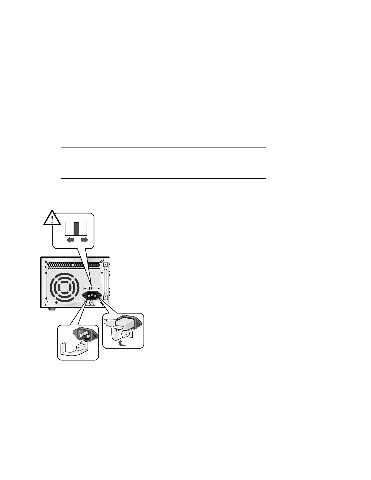
1.1 Powering Up the System
To power up the system, check your power setting (DS10 only),
then press the On/Off button ❶ to the On position. Check the
control panel LEDs. See Figure 1–1 and Figure 1–2 for the DS10,
and Figure 1–3 for the DS10L.
Figure 1–1 Check Power Setting – DS10
115V
230V
PK1047a
DS10 / DS10L Console Reference
1-2
Page 15

Figure 1–2 Location of DS10 Control Panel and On/Off Button
PK1043b
Table 1–1 Control Panel Functions – DS10
Symbol Function
Halt button. Under OpenVMS an d T ru6 4 U N IX , suspe nds the operating
system and returns control to the SRM conso le.
Environmental amber LE D . O n indicate s Temperature or Fan LE D s ar e
on. Flashes when oper at ing s ystem invokes it as an ale rt.
Temperature amber LED. On indicates internal temperature exceeds
operating condit ion s. T he sys te m shu ts d ow n 30 seconds after this LED
lights.
Fan amber LED. On indicates th at at least one of the th re e fans in the
system has failed. The system shuts down 30 s econds after this LED lig ht s.
Disk Activity green LED . F las hes w hen interna l system disks are
accessed.
Power Present green LED. On when power is present in the system.
Power button. Push in to star t th e system and connect power. Push aga in
to remove power and s to p the s ystem.
Operations 1-3
Page 16

Figure 1–3 Location of DS10L Control Panel and On/Off Button
1
PK2216
Table 1–2 Control Panel Functions - DS10L
Symbol Function
Halt button. Under OpenVMS an d T ru6 4 U N IX , suspe nds the operating
system and returns control to the SRM conso le.
Environmental amber LE D . O n indicate s Temperature or Fan LE D s ar e
on. Flashes when oper at ing s ystem invokes it as an ale rt.
Temperature amber LED. On indicates internal temperature exceeds
operating condit ion s. T he sys te m shu ts d ow n 30 seconds after this LED
lights.
Fan amber LED. On indicates th at at least one of the th re e fans in the
system has failed. The system shuts down 30 s econds after this LED lig ht s.
Disk Activity green LED . F las hes w hen interna l system disks are
accessed.
Power Present green LED. On when power is present in the system.
Power button ❶. Push in to start the system and connect po wer. Push
again to remove pow er a nd s top th e system.
DS10 / DS10L Console Reference
1-4
Page 17

1.2 Power-Up Display
DS10 systems have four physical PCI slots; the DS10L system
has one, hence the different power-up displays shown below.
Testing begins after pressing the On/Off button, and screen text
similar to that in Example 1–1 displays (if the console terminal is
a serial terminal connected to the COM1 port), along with status
messages in the control panel display. If the console terminal is
a graphics monitor, only the last few lines of the power-up
display print.
Example 1–1 Power-Up Display – DS10
256 Meg of sys te m memory ➊
probin g ho se 0, PCI
probing PCI-to-ISA bridge, bus 1
probing PCI-to-PCI bridge, bus 2 ➋
bus 0, slo t 9 -- ew a -- DE500-BA Ne twork Cont roller
bus 0, slo t 11 -- ew b -- DE500-B A Network Co ntroller
bus 0, slot 13 -- dqa -- Acer Labs M1543C IDE
bus 0, slot 13 -- dqb -- Acer Labs M1543C IDE
bus 0, slot 14
bus 2,
bus 2,
bus 2,
bus 0,
bus 0,
Testing the System
Testing the Disks (read only)
>>> ➐
➍slot 0 -- pka -- NCR 53C875
➍slot 1 -- pkb -- NCR 53C875
➍slot 2 -- ew c -- DE500-A A Network Controll er
➎ slot 16 -- pkc -- QLogic ISP1020
➏ slot 17 -- dra -- Mylex DAC960
➌-- vga -- DEC PowerStorm
➋
Operations 1-5
Page 18

Figure 1–4 Physical Numbering for DS10 PCI Slots
PCI Slot 4
PCI Slot 3
PCI Slot 2
PCI Slot 1
64 Bit
64 Bit
64 Bit
32 Bit
PK1045-99
➊ Memory size is determined.
➋ The PCI bridges and attendant buses (indicated as IODn by the console)
are probed and the devices are reported. I/O adapters are configured.
➌
Power-up slot 14 corresponds to the bottom physical slot, slot 1.
Slot Location Physical Slot Number Logical Slot Number
Top 4 17
Second from top 3 16
Second from bottom 2 15
Bottom 1 14
➍ These devices are behind bridge of the card in logical slot 15, physical slot
2, second from the bottom.
➎
This device in is logical slot 16, physical slot 3.
➏ Logical slot 17 is physical slot 4, the top slot.
➐ The SRM console banner and prompt (>>>) are printed.
The SRM console is a command-line interface you use to set or read system
parameters.
If the auto_action environment variable is set to boot or restart and the
os_type environment variable is set to unix or openvms, the Tru64 UNIX
or OpenVMS operating system boots. See Section 2.18 for information on
environment variables.
DS10 / DS10L Console Reference
1-6
Page 19

Example 1–2 Power-Up Display - DS10L Serial and Graphics
Consoles
Note: There is only one PCI slot on the DS10L; its logical slot number is 17.
Serial Console
256 Meg of sys te m memory ➊
probin g ho se 0, PCI
probing PCI-to-ISA bridge, bus 1
bus 0, slo t 9 -- ew a -- DE500-BA Ne twork Cont roller
bus 0, slo t 11 -- ew b -- DE500-B A Network Co ntroller
bus 0, slot 13 -- dqa -- Acer Labs M1543C IDE
bus 0, slot 13 -- dqb -- Acer Labs M1543C IDE
bus 0,
Testin g th e Sy stem
Testin g th e di sks (read on ly)
Testing the Network
System Temperature is 36 degrees C
Initializing GCT/FRU at 1f6000
COMPAQ AlphaServer DS10L 466 MHz Console V5.7-0 Jan 14 2000 09:59:58
>>> ➍
➊
➋
➌ slot 17 -- dra -- Mylex DAC960
Memory size is determined.
The PCI bridges and attendant buses (indicated as IODn by the console)
are probed and the devices are reported. I/O adapters are configured.
➋
➌ The power-up logical slot is always 17 on the DS10L.
➍ The SRM console banner and prompt (>>>) are printed.
The SRM console is a command-line interface you use to set or read system
parameters.
If the auto_action environment variable is set to boot or restart and the
os_type environment variable is set to unix or openvms, the Tru64 UNIX
or OpenVMS operating system boots.
See Section 2.18 for information on environment variables. See Chapter 2
for SRM console and AlphaBIOS information.
Operations 1-7
Page 20

Graphics Console
Os_type UNIX-console CIPCA drive not started
Testin g th e Sy stem
Testin g th e di sks (read on ly)
Testing the Network
System Temperature is 36 degrees C
Initializing GCT/FRU at 1f6000
COMPAQ AlphaServer DS10L 466 MHz Console V5.7-0 Jan 13 2000 09:59:58
DS10 / DS10L Console Reference
1-8
Page 21

1.3 Booting Tru64 UNIX
Tru64 UNIX® can be booted from a local disk or a remote disk
through an Ethernet connection. Refer to the documentation
shipped with the operating system for booting instructions.
1.3.1 Booting from a Local Disk
Example 1–3 Booting Tru64 UNIX from a Local Disk
>>> sho device ➊
dka100.1.0.2000.0 DKA100 RZ1CB-CA LYJ0 ➋
dka300.3.0.2000.0 DKA300 RZ1CB-CA LYJ0
dka500.5.0.2000.0 DKA500 RZ1EF-AB 0370
dkb0.0.0.2001.0 DKB0 RZ1CB-CA LYJ0
dkb200.2.0.2001.0 DKB200 RZ1DB-CS 0307
dkb400.4.0.2001.0 DKB400 RZ1CB-CA LYJ0
dkc0.0.0.16.0 DKC0 RZ1CB-BA LYG0
dkc200.2.0.16.0 DKC200 RZ1CB-BA LYG0
dqa1.1.0.13.0 DQA1 CD-532E 1.0A
dra1.0.0.17.0 DRA1 1 Member JBOD
dra2.0.0.17.0 DRA2 1 Member JBOD
dva0.0.0.0.0 DVA0
ewa0.0.0.9.0 EWA0 08-00-2B-86-1B-BA
ewb0.0.0.11.0 EWB0 08-00-2B-86-1B-BB
ewc0.0.0.2002.0 EWC0 00-06-2B-00-26-1C
pka0.7.0.2000.0 PKA0 SCSI Bus ID 7
>>> boot -file vmunix -flags a dkc0 ➌
(boot dkc0.0.0.9.0 -file vmunix -flags a)
block 0 of dkc0.0.0.9.0 is a valid boot block
reading 16 blocks from dkc0.0.0.9.0
bootstrap code read in
base = 1ee000, image_start = 0, image_bytes = 2000
initializing HWRPB at 2000
initializing page table at 1fff0000
initializing machine state
setting affinity to the primary CPU
jumping to bootstrap code
Tru64 UNIX boot - Fri Aug 7 20:30:19 EDT 1999
Loading vmunix ...
. . .
The system is ready.
Tru64 UNIX Version V4.0E (sabl28.eng.pko.dec.com) console
login:
************************************************************************
* Starting Desktop Login on display :0...
* Wait for the Desktop Login screen before logging in.
************************************************************************
➍
Operations 1-9
Page 22

➊
The show device command displays device information, including
name and type of connection to the system. See Section 2.3.2 for a
description of the show device command and the device naming
convention.
➋ The operating system is on the third disk connected to the system
through the controller in slot 3 of the PCI. The name of this device,
dkc0, is used as an argument to the boot command.
➌
This command loads Tru64 UNIX from the disk dkc0, using the boot
file vmunix and autobooting to multiuser mode. See Section 2.5 for a
description of the boot command.
The boot command accepts the name of a boot device, a boot file
name through the -file option, and boot flags through the -flags
option. The environment variables bootdef_dev, boot_file, and
boot_osflags can also be used to specify the default boot device or
device list, the default boot file, and flag information. When an option
and the corresponding environment variable are both in a command
string, the option overrides the environment variable. The value of
the environment variable, however, is not changed. See Section 2.18
for information about environment variables.
➍ The operating system banner displays.
DS10 / DS10L Console Reference
1-10
Page 23

1.3.2 Booting from a Remote Disk
Example 1–4 Booting Tru64 UNIX from a Remote Disk
>>> show device ➊
. . .
ewa0.0.0.8.0 EWA0 08-00-2B-E2-9C-60
>>>
>>> boot -flags an -p rotocols bootp ewa ➌
(boot ewa0.0.0.4.1 -f lags an)
Building FRU table
➋
Trying BOOTP boot
Broadcasting BOOTP Re quest...
Received BOOTP Packet File Name: /var/adm/ris/ris0. alpha/hvmunix
local inet address: 1 6.122.128.26
remote inet address: 16.122.128.59
TFTP Read File Name: /var/adm/ris/ris0.alpha/ hvmunix
..................... ........................ ........................ .....................
bootstrap code read i n
base = 200000, image_ start = 0, image_bytes = 9a0fa0
initializing HWRPB at 2000
initializing page tab le at 1f2000
initializing machine state
setting affinity to t he primary CPU
jumping to bootstrap code
Secondary boot progra m - Thu Aug 1 22:33:13 E ST 1999
Loading vmunix ...
.
.
.
The system is ready.
Tru64 UNIX Version V4.0E (sabl28.eng.pko.dec.com) console
.
➍
Operations 1-11
Page 24

➊
The show device command displays device information, including
name and type of connection to the system. See Section 2.3.2 for a
description of the show device command and the device naming
convention.
➋ The operating system is on a remote disk accessed through the
Ethernet controller in slot 4 of the PCI. The name of this device,
ewa0, is used as an argument to the boot command.
➌ This command loads Tru64 UNIX from ewa0, autobooting to
multiuser mode. See Section 2.5 for a description of the boot
command.
The boot command accepts the name of a boot device, a boot file
name through the -file option, and boot flags through the -flags
option. The environment variables bootdef_dev, boot_file, and
boot_osflags can also be used to specify the default boot device or
device list, the default boot file, and flag information. When an option
and the corresponding environment variable are both in a command
string, the option overrides the environment variable. The value of
the environment variable, however, is not changed. See Section 2.18
for information about environment variables.
➍
The operating system banner displays.
DS10 / DS10L Console Reference
1-12
Page 25

1.4 Installing Tru64 UNIX
Tru64 UNIX is installed from the CD-ROM. Refer to the
documentation shipped with the CD-ROM for installation
instructions.
Example 1–5 Installing Tru64 UNIX
>>> show device
. . .
dka500.5.0.7.1 DKA500 RRD47 1337
. . .
>>>
>>> boot dka500
(boot dka500.5.0.7.1 -flags A)
block 0 of dka500.5.0.7.1 is a valid boot block
reading 16 blocks from dka500.5.0.7.1
bootstrap code read in
base = 1ee000, image_start = 0, image_bytes = 2000
initializing HWRPB at 2000
initializing page table at 1fff0000
initializing machine state
setting affinity to the primary CPU
jumping to bootstrap code
Tru64 UNIX boot - Thu Jul 16 16:59:31 EDT 1999
Loading vmunix ...
.
.
.
INIT: SINGLE-USER MODE
Initializing system for Tru64 UNIX installation. Please wait...
*** Performing CDROM Installation
Loading installation process and scanning system hardware.
➊
➊
[The “Welcome to the Tru64 UNIX Installation Procedure” appears.]
➋
Operations 1-13
Page 26

➊
Use the boot command to install the operating system from the CDROM, which is either dka500 or dqa0.
➋
See your operating system documentation for further installation
instructions.
DS10 / DS10L Console Reference
1-14
Page 27

1.5 Booting OpenVMS
OpenVMS can be booted from a local disk, a disk connected
through a cluster, or a remote disk through an Ethernet
connection. Refer to the documentation shipped with the
operating system for booting instructions.
1.5.1 Booting OpenVMS from a Local Disk
Example 1–6 Booting OpenVMS from a Local Disk
>>> show device ➊
dka200.2.0.7.1 DKA200 RZ1CB-CA LYJ0
>>>
>>> show boot_reset ➋
boot_reset ON
>>> show bootdef_dev
bootdef_dev dka200.2.0.7.1
>>> boot ➍
(boot dka200.2.0.7.1 -flags 0,0)
block 0 of dka200.2.0.7.1 is a valid boot block
reading 893 blocks from dka200.2.0.7.1
bootstrap code read in
base = 1fa000, image_start = 0, image_bytes = 6fa00
initializing HWRPB at 2000
initializing page table at 1fff0000
initializing machine state
setting affinity to the primary CPU
jumping to bootstrap code
OpenVMS (TM) Alpha Operating System, Version 7.1-2
$!Copyright(c) 1999 Digital Equipment Corporation. All rights reserved.
%STDRV-I-STARTUP, OpenVMS startup begun at 30-JUL-1999 11:47:11.04
%MSCPLOAD-I-CONFIGSCAN, enabled automatic disk serving
. . .
. . .
➌
Continued on next page
Operations 1-15
Page 28

Example 1–6 Booting OpenVMS from a Local Disk (Continued)
. . .
The OpenVMS system is now executing the site-specific startup commands.
. . .
Welcome to OpenVMS (TM) Alpha Operating System, Version V7.1-2
Username:
➊
The show device command displays device information. See Section
2.3.2 for a description of the show device command and the device
naming convention.
➋
The boot_reset environment variable was previously set to “on,”
causing the power-up trace to display when the system initializes (see
Section 1.2). See Section 2.18 for commands used with environment
variables.
➌
The bootdef_dev environment variable specifies the default boot
device. In this example, the default boot device was previously set to
dka200.2.0.7.1.
➍
No boot device is specified in the boot command; the default boot
device was set with the environment variable. See Section 2.5 for a
description of the boot command.
The boot command accepts the name of a boot device, a boot file
name through the -file option, and boot flags through the -flags
option. The environment variables bootdef_dev, boot_file, and
boot_osflags can also be used to specify the default boot device or
device list, the default boot file, and flag information. When an option
and the corresponding environment variable are both in a command
string, the option overrides the environment variable. The value of
the environment variable, however, is not changed. See Section 2.18
for information about environment variables.
➎
➎
The operating system banner displays.
DS10 / DS10L Console Reference
1-16
Page 29

1.5.2 Booting OpenVMS from a Disk on a Cluster
Example 1–7 Booting OpenVMS from a Disk on a Cluster
>>> show bootdef_dev ➊
bootdef_dev dua110.0.0.8.0
>>> show device
dua110.0.0.8.0 $1$DIA110 (DENVER) RF74
➋
. . .
➌
. . .
>>> boot
➍
(boot dua110.0.0.8.0 -flags 0)
Building FRU table
.
.
.
Welcome to OpenVMS Alpha (TM) Operating System, Version V7.1-2
➎
Operations 1-17
Page 30

➊
The bootdef_dev environment variable specifies the default boot
device.
➋
The show device command displays device information, including
name and type of connection to the system. See Section 2.3.2 for a
description of the show device command and the device naming
convention.
➌ The disk dua110.0.0.8.0 is on the cluster that includes this system.
➍
No boot device is specified in the boot command; the default boot
device was set with the environment variable. See Section 2.5 for a
description of the boot command.
The boot command accepts the name of a boot device, a boot file
name through the -file option, and boot flags through the -flags
option. The environment variables bootdef_dev, boot_file, and
boot_osflags can also be used to specify the default boot device or
device list, the default boot file, and flag information. When an option
and the corresponding environment variable are both in a command
string, the option overrides the environment variable. The value of
the environment variable, however, is not changed. See Section 2.18
for information about environment variables.
➎ The operating system banner prints.
DS10 / DS10L Console Reference
1-18
Page 31

1.5.3 Booting OpenVMS from a Remote Disk
Example 1–8 Booting OpenVMS from a Remote Disk
>>> show device ➊
. . .
ewa0.0.0.8.0 EWA0 08-00-2B-E2-9C-60
>>>
>>> boot ewa0 -flags 0 ➋
. . .
➊
(boot ewa0.0.0.2.0 -flags 0)
Building FRU table
Trying MOP boot..............
Network load complete.
Welcome to OpenVMS Alpha (TM) Operating System, Version V7.1-2
. . .
➌
Operations 1-19
Page 32

➊
The show device command displays device information, including
name and type of connection to the system. In this example the
Ethernet connection is ewa0. See Section 2.3.2 for a description of the
show device command and the device naming convention.
➋
The boot command specifies ewa0 as the boot device. See Section 2.5
for a description of the boot command.
The boot command accepts the name of a boot device, a boot file
name through the -file option, and boot flags through the -flags
option. The environment variables bootdef_dev, boot_file, and
boot_osflags can also be used to specify the default boot device or
device list, the default boot file, and flag information. When an option
and the corresponding environment variable are both in a command
string, the option overrides the environment variable. The value of
the environment variable, however, is not changed. See Section 2.18
for information about environment variables.
➌ The operating system banner prints.
DS10 / DS10L Console Reference
1-20
Page 33

1.6 Installing OpenVMS
OpenVMS is installed from the CD-ROM. Refer to the
documentation shipped with the OpenVMS kit for complete
installation instructions.
Example 1–9 Installing OpenVMS
>>> boot -flags 0,0 dka500 ➊
Initializing...
SROM V3.0 on cpu0
.
. [The initialization displ ay prints. See Section 1 .2.]
.
AlphaServer DS10 Console V5. 7-0 Jan 13 2000 15:17:48
CPU 0 booting
(boot dka500.5.0.1.1 -flags 0,0)
Building FRU table
block 0 of dka500.5.0.1.1 is a valid boot block
reading 1002 blocks from dka 500.5.0.1.1
bootstrap code read in
base = 200000, image_start = 0, image_bytes = 7d400
initializing HWRPB at 2000
initializing page table at 1 f2000
initializing machine state
setting affinity to the prim ary CPU
jumping to bootstrap code
OpenVMS (TM) Alpha Opera ting System, Version 7.1 x
%SMP-I-SECMSG, CPU #01 messa ge: P01>>>START
%SMP-I-CPUBOOTED, CPU #01 ha s joined the PRIMARY CPU in multiprocessor opera tion
Installing required known fi les...
Configuring devices...
************************ ************************ ****************
You can install or upgrade the OpenVMS Alpha operat ing system
or you can install or upgra de layered products that are included
on the OpenVMS Alpha operat ing system CD-ROM.
You can also execute DCL co mmands and procedures to perform
"standalone" tasks, such as backing up the system d isk.
➋
Continued on next page
Operations 1-21
Page 34

Example 1–9 Installing OpenVMS (Continued)
Please choose one of the fo llowing:
1) Install or upgrade O penVMS Alpha Version 7.1 x
2) List layered product kits that this procedur e can install
3) Install or upgrade l ayered product(s)
4) Execute DCL commands and procedures
5) Shut down this syste m
Enter CHOICE or ? to repeat menu: (1/2/3/4/5/?)
➊
Use the boot command to install the operating system from the CDROM, which is either dka500 or dqa0.
➋
See your operating system documentation for installation
instructions.
DS10 / DS10L Console Reference
1-22
Page 35

1.7 Switching Between Operating Systems
The system supports multiple operating systems on different
system and data disks not in the machine at the same time. That
is, you can have a set of disks for each operating system.
CAUTION: This operation is not for the faint hearted especially if you have a
shadow system disk and shadow arrays. The file structures of the
operating systems are incompatible and therefore all disks must be
remov ed from the system and up on reinstallati on must be replaced
in exactly the same physical locations. It is therefore necessary to
keep track of the location of each disk in the system.
1.7.1 Switching to Tru64 UNIX or OpenVMS
Use the following procedure:
Shut down the operating system and power off the system.
1.
Remove and mark the physical location of each disk in the system.
2.
Either place blank disks or your Tru64 UNIX or OpenVMS disk set into the
3.
system. No matter which disk set you are placing into the system, be
sure that each disk is placed in the same physical location from
which it was removed.
4.
Power on the system.
Set the operating system at the console prompt (see Section 2.18.11).
5.
Press the Halt/Reset button to reset the system.
6.
Either install Tru64 UNIX (see Section 1.4) or OpenVMS (see Section 1.6) or
7.
boot the operating system.
Operations 1-23
Page 36

1.8 Updating Firmware
Start the Loadable Firmware Update (LFU) utility by issuing the
lfu command at the SRM console prompt, booting it from the
CD-ROM while in the SRM console.
Example 1–10 Starting LFU from the SRM Console
Revision levels and devi ces listed are for example only; your results may va ry.
>>> lfu
Checking dqa0.0.0.13.0 for the option firmware files. . .
Checki ng dva 0 for the opti on firmwar e files. . .
Option firmware files were not found on CD or floppy.
If you wan t to loa d the option s firmware ,
please enter the device on which the files are located(ewa0),
or just hi t <r et urn> to proc eed with a sta ndard console upda te: dva0
Please enter the name of the options firmware files list, or
Hit <ret ur n> to use the defa ult filena me (ds10fw.txt) :
Copyin g ds 10 fw.txt fro m dva0. . .
Copying PC264NT.ROM from dva0. . .
Copying DS10SRM.ROM from dva0. . .
DS10 / DS10L Console Reference
1-24
Page 37

***** Loadable Firmware Update Uti lity *****
------------------------------------------------------------------
Function Description
------------------------------------------------------------------
Display Displays the system’s configuration table.
Exit Done exit LFU (reset).
List Lists the device, revision, firmware name, and update
revision.
Readme Lists important release information.
Update Replace s cu rr ent firmwa re with load able data image.
Verify Compares loadable and hardware images.
? or Help Scrolls this function table.
------------------------------------------------------------------
UPD> update *
Confir m up da te on:
nt
srm
[Y/(N)]y
WARNIN G: upd ates may tak e several mi nutes to complete fo r each
device.
DO NOT ABORT!
nt Updating to 5.70... Verifying 5.70... PASSED.
srm Updating to 5. 7-0... Veri fying 5.7-0... PASS ED.
UPD> exit
NOTE: If the system has been shut down from a booted program (most
commonly, the operating system) or in some other way halted back to
the SRM console, the system must be reset before running LFU.
Use the Loadable Firmware Update (LFU) utility to update system firmware.
From the SRM console, start LFU by issuing the lfu command (see
Example 1–10). Also from the SRM console, LFU can be booted from the Alpha
CD-ROM (V5.4 or later), as shown in Example 1–11.
A typical update procedure is:
1. Start LFU.
2. Use the LFU list command to show the revisions of modules that LFU can
update and the revisions of update firmware.
3. Use the LFU update command to write the new firmware.
Operations 1-25
Page 38

4. Use the LFU exit command to go back to the console.
The sections that follow show examples of updating firmware from the local CDROM, the local floppy, and a network device.
Example 1–11 Booting LFU from the CD-ROM
Revision levels and devi ces listed are for example only; your results may va ry.
>>> show device . . .
dka500.5.0.7.1 DKA500 RRD47 1645
>>> boot dka500
(boot dka500.5.0.7.1 -flags 0,0)
block 0 of dka500.5.0.7.1 is a valid boot block
. .
jumping to bootstrap code
The default bootfile for this platform is
[DS10]DS10_LFU.EXE
Hit <RETURN> at the prompt to use the default bootfile.
Bootfile: <CR>
Starting Firmware Update Utility
***** Loadable Firmware Update Utility *****
. . .
UPD>
. . .
DS10 / DS10L Console Reference
1-26
Page 39

1.8.1 Updating Firmware from Floppy Disks
Create two update diskettes before starting LFU: one for console
updates and one for I/O. See Section 1.8.2 for an example of the
update procedure.
Table 1–3 File Locations for Creating Update Diskettes on a PC
Console Update Diskette I/O Update Diskette
ds10fw.txt ds10fw.txt
pc264nt.rom ccmab022.sys
ds10srm.rom dfxaa310.sys
kzpsaa12.sys
cipca420.sys
NOTE: The filenames above are for example only, and may vary according to
where you obtained the update files.
1. Download the update files from the Internet.
On a PC, copy files onto two FAT-formatted diskettes as shown
2.
in Table 1–3.
Operations 1-27
Page 40

1.8.2 Performing the Update from Floppy Disks
Insert an update diskette (see Section 1.8.1) into the floppy
drive. Start LFU and select dva0 as the load device.
Example 1–12 Updating Firmware from the Floppy Disk
Revision levels and devi ces listed are for example only; your results may va ry.
>>> lfu
Checking dqa0.0.0.13.0 for the option firmware files. . .
Checki ng dva 0 for the opti on firmwar e files. . .
Option firmware files were not found on CD or floppy.
If you wan t to loa d the option s firmware ,
please enter the device on which the files are located(ewa0),
or just hi t <r et urn> to proc eed with a sta ndard console upda te: dva0
Please enter the name of the options firmware files list, or
Hit <ret ur n> to use the defa ult filena me (ds10fw.txt) :
Copyin g ds 10 fw.txt fro m dva0. . .
Copying PC264NT.ROM from dva0. . .
Copying DS10SRM.ROM from dva0. . .
DS10 / DS10L Console Reference
1-28
Page 41

***** Loadable Firmware Update Uti lity *****
------------------------------------------------------------------
Function Description
------------------------------------------------------------------
Display Displays the system’s configuration table.
Exit Done exit LFU (reset).
List Lists the device, revision, firmware name, and update
revision.
Readme Lists important release information.
Update Replace s cu rr ent firmwa re with load able data image.
Verify Compares loadable and hardware images.
? or Help Scrolls this function table.
------------------------------------------------------------------
UPD> update *
Confir m up da te on:
nt
srm
[Y/(N)]y
WARNIN G: upd ates may tak e several mi nutes to complete fo r each
device.
DO NOT ABORT!
nt Updating to 5.70... Verifying 5.70... PASSED.
srm Updating to 5. 7-0... Veri fying 5.7-0... PASS ED.
UPD> exit
NOTE: If the system has been shut down from a booted program (most
commonly, the operating system) or in some other way halted back to
the SRM console, the system must be reset before running LFU.
Operations 1-29
Page 42

1.8.3 Updating Firmware from a Network Device
Copy files to the local MOP server’s MOP load area, start LFU,
and select ewa0 as the load device.
Example 1–13 Updating Firmware from a Network Device
Revision levels and devi ces listed are for example only; your results may va ry.
***** Loadable Firmware Update Utility *****
Select firmware load device (cda0, dva0, ewa0), or
Press <return> to bypass loading and proceed to LFU: ewa0
Please enter the name of the options firmware files list, or
Press <return> to use the default filename [DS10FW]:
Copying DS10FW from EWA0 .
Copying CCMAB022 from EWA0 .
Copying DFXAA310 from EWA0 ...........................
Copying KZPSAA12 from EWA0 ............
Copying CIPCA420 from EWA0 .
.
.
.
UPD> list
➊
➋
➌
Device Current Revision Filename Update Revision
Nt 5.69 nt_fw 5.70
Srm 5.6-2 srm_fw 5.7-0
DS10 / DS10L Console Reference
1-30
Continued on next page
Page 43

Before starting LFU, download the update files from the Internet. You will
need the files with the extension .SYS. Copy these files to your local MOP
server’s MOP load area.
➊
Select the device from which firmware will be loaded. The choices are
the CD-ROM, the internal floppy disk, or a network device. In this
example, a network device is selected.
➋
For the SRM console, AlphaBIOS console, and I/O adapter firmware,
select the file that has the firmware update, (ds10fw.txt ), or press
Enter.
In this example the default file, which has both console firmware
(AlphaBIOS and SRM) and I/O adapter firmware, is selected.
➌
Use the LFU list command to determine the revision of firmware in a
device and the most recent revision of that firmware available in the
selected file. In this example, the resident firmware for each console
(SRM and AlphaBIOS) and I/O adapter is at an earlier revision than
the firmware in the update file.
Continued on next page
Operations 1-31
Page 44

Example 1–13 Updating Firmware from a Network Device
(Continued)
UPD> update * -all ➍
WARNING: updates may take several minutes to complete for each device.
DO NOT ABORT!
AlphaBIOS Updating to V6.40-1... Verifying V6.40-1... PASSED.
DO NOT ABORT!
kzpsa0 Updating to A11 ... Verifying A11... PASSED.
DO NOT ABORT!
kzpsa1 Updating to A11 ... Verifying A11... PASSED.
UPD> exit
➍
The update command updates the device specified or all devices. In
this example, the wildcard indicates that all devices supported by the
selected update file will be updated. Typically LFU requests
confirmation before updating each console’s or device’s firmware. The
-all option eliminates the update confirmation requests.
➎
The exit command returns you to the console from which you entered
LFU (either SRM or AlphaBIOS).
➎
DS10 / DS10L Console Reference
1-32
Page 45

1.8.4 LFU Commands
The commands summarized in Table 1–4 are used to update
system firmware.
Table 1–4 LFU Command Summary
Command Function
display
help
readme
update
verify
display
The display command shows the physical configuration of the system. Display
is equivalent to issuing the SRM console command show configuration.
Because it shows the slot for each module, display can help you identify the
location of a device.
exit
The exit command terminates the LFU program, causes system initialization
and testing, and returns the system to the console from which LFU was called.
Shows the physical configuration of the system.
exit
Terminates the LFU program.
Displays the LFU command list.
lfu
Restarts the LFU program.
list
Displays the inventory of update firmware on the selected device.
Lists release notes for the LFU program.
Writes new firmware to the module.
Reads the firmware from the module into memory and compares
it with the update firmware.
Operations 1-33
Page 46

help
The help (or ?) command displays the LFU command list, shown below.
--------------------- ------------------------ ------------------------
Function Descript ion
--------------------- ------------------------ ------------------------
Display Displays the system’s conf iguration table.
Exit Done exi t LFU (reset).
List Lists th e device, revision, firm ware name, and update
revision .
Lfu Restarts LFU.
Readme Lists im portant release informat ion.
Update Replaces current firmware with l oadable data image.
Verify Compares loadable and hardware i mages.
? or Help Scrolls this function table.
----------------------------------------------------------
lfu
The lfu command restarts the LFU program. This command is used when the
update files are on a floppy disk. The files for updating both console firmware
and I/O firmware are too large to fit on a 1.44 MB disk, so only one type of
firmware can be updated at a time. Restarting LFU enables you to specify
another update file.
list
The list command displays the inventory of update firmware on the CD-ROM,
network, or floppy. Only the devices listed at your terminal are supported for
firmware updates.
The list command shows three pieces of information for each device:
• Current Revision — The revision of the device’s current firmware
• Filename — The name of the file used to update that firmware
• Update Revision — The revision of the firmware update image
readme
The readme command lists release notes for the LFU program.
DS10 / DS10L Console Reference
1-34
Page 47

update
The update command writes new firmware to the module. Then LFU
automatically verifies the update by reading the new firmware image from the
module into memory and comparing it with the source image.
To update more than one device, you may use a wildcard but not a list. For
example, update k* updates all devices with names beginning with k, and
update * updates all devices. When you do not specify a device name, LFU tries
to update all devices; it lists the selected devices to update and prompts before
devices are updated. (The default is no.) The -all option eliminates the update
confirmation requests, enabling the update to proceed without operator
intervention.
CAUTION: Never abort an update operation.
Aborting corrupts the firmware on the module.
verify
The verify command reads the firmware from the module into memory and
compares it with the update firmware. If a module already verified successfully
when you updated it, but later failed tests, you can use verify to tell whether
the firmware has become corrupted.
Operations 1-35
Page 48

1.9 Using the Halt Button
Under OpenVMS and Tru64 UNIX, the halt button pauses the
operating system.
Use the Halt button to halt the Tru64 UNIX or OpenVMS operating system
when it hangs, clear the SRM console password (see Section 2.9.2), or force a
halt assertion (see Section 1.10). The Halt button operates like issuing an SRM
halt command.
Figure 1–5 Halt/Reset Button – DS10
PK1043b
DS10 / DS10L Console Reference
1-36
Page 49

Figure 1–6 Halt/Reset Button - DS10L
1
PK2220
1.9.1 Using Halt to Shut Down the Operating System
You can use the Halt button if the Tru64 UNIX or OpenVMS operating system
hangs. Pressing the Halt button halts the operating system back to the SRM
console firmware. From the console, you can use the crash command to force a
crash dump at the operating system level. See Section 2.12 for an example.
1.9.2 Using Halt to Clear the Console Password
The SRM console firmware allows you to set a password to prevent unauthorized access to the console. If you forget the password, the Halt button, with the
login command, lets you clear the password and regain control of the console.
Section 2.9.2 describes the procedure.
Operations 1-37
Page 50

1.10 Halt Assertion
A halt assertion allows you to disable automatic boots of the
operating system so that you can perform tasks from the SRM
console.
Under certain conditions, you might want to force a “halt assertion.” A halt
assertion differs from a simple halt in that the SRM console “remembers” the
halt. The next time you power up, the system ignores the SRM power-up script
(nvram) and ignores any environment variables that you have set to cause an
automatic boot of the operating system. The SRM console displays this
message:
Halt assertion detected
NVRAM power-up script not executed
AUTO_ACTION=BOOT/RESTART and OS_TYPE=NT ignored, if applicable
Halt assertion is useful for disabling automatic boots of the operating system
when you want to perform tasks from the SRM console. It is also useful for
disabling the SRM power-up script if you have accidentally inserted a command
in the script that will cause a system problem. These conditions are described
in the sections “Disabling Autoboot” and “Disabling the SRM Power-Up Script.”
You can force a halt assertion using the Halt button, the RMC halt command,
or the RMC haltin command. Observe the following guidelines for forcing a
halt assertion.
1.10.1 Halt Assertion with Halt Button or RMC Halt Command
Press the Halt button on the local system (or enter the RMC halt command
from a remote system) approximately five seconds after starting power up or
when the SRM console is running. The system halts at the SRM console, and
the halt status is saved. The next time the system powers up, the saved halt
status is checked.
NOTE: Wait 5 seconds after the system begins powering up before pressing the
Halt button or remo t ely en tering the RMC halt command. Pres s the
button for several se conds.
DS10 / DS10L Console Reference
1-38
Page 51

1.10.2 Halt Assertion with RMC Haltin Command
Enter the RMC haltin command at any time except during power-up. For
example, enter haltin during an operating system session or when the
AlphaBIOS console is running.
If you enter the RMC haltin command during a Tru64 UNIX or OpenVMS
session, the system halts back to the SRM console, and the halt status is saved.
The next time the system powers up, the saved halt status is checked.
If you enter the RMC haltin command when AlphaBIOS is running, the
interrupt is ignored. However, you can enter the RMC haltin command
followed by the RMC reset command to force a halt assertion. Upon reset, the
system powers up to the SRM console, but the SRM console does not load the
AlphaBIOS console.
The haltin command should always be followed by the haltout command.
1.10.3 Clearing a Halt Assertion
Clear a halt assertion as follows:
• If the halt assertion was caused by pressing the Halt button or remotely
entering the RMC halt command, the console uses the halt assertion once,
then clears it.
• If entering the RMC haltin command caused the halt assertion, enter the
RMC haltout command or cycle power on the local system.
1.10.4 Disabling Autoboot
The system automatically boots the selected operating system at power-up or
reset if the following environment variables are set:
• For Tru64 UNIX and OpenVMS, the SRM environment variables os_type,
auto_action, bootdef_dev, boot_file, and boot_osflags
You might want to prevent the system from autobooting so you can perform
tasks from the SRM console. Use one of the methods described previously to
force a halt assertion. When the SRM console prompt is displayed, you can
enter commands to configure or test the system. Chapter 2 describes the SRM
console commands and environment variables.
Operations 1-39
Page 52

1.10.5 Disabling the SRM Power-Up Script
The system has a power-up script (file) named “nvram” that runs every time the
system powers up. If you accidentally insert a command in the script that will
cause a system problem, disable the script by using one of the methods described
previously to force a halt assertion. When the SRM console prompt is displayed,
edit the script to delete the offending command. See Section 2.4 for more
information on editing the nvram script.
DS10 / DS10L Console Reference
1-40
Page 53

Chapter 2
SRM and AlphaBIOS Consoles
The SRM console is the command-line interface that supports the Tru64 UNIX
and OpenVMS operating systems. The SRM console is used to bootstrap the
operating system, configure and test the system hardware, examine system
options for errors, and set or change environment variables. The AlphaBIOS
console is used to run certain utilities.
This chapter describes the SRM and AlphaBIOS console commands and
environment variables. Sections in this chapter are:
• Invoking the SRM Console
• Commands
• Show Commands
• Creating a Power-Up Script
• Booting the Operating System
• Configuring a PCI NVRAM
Module
• Testing the System
• Set Commands
• Secure Mode
• Stopping and Starting CPU
NOTE: In many ways the DS10 and DS10L systems are identical. This
manual uses DS10 systems for most illustrations and examples. Where
significant differences exist, an illustration or example of a DS10L is
presented separately.
• Updating Firmware
• Forcing a System Crash Dump
• Using Environment Variables
• Depositing and Examining Data
• Reading a File
• Initializing the System
• Finding Help
• Environment Variable
Summary
• Switching from SRM to
AlphaBIOS Console
• Running the AlphaBIOS
Console
SRM and AlphaBIOS Consoles 2-1
Page 54

2.1 Invoking the SRM Console
When a system is powered up, the SRM console runs and either
remains running or passes control to another console or an
operating system. If the system is already running, invoke the
SRM console by shutting down the operating system or by
pressing the Halt button on the control panel.
If you are running Tru64 UNIX or OpenVMS Alpha operating system
• The preferred method to invoke the SRM console is to shut down the
operating system according to the procedure described in your operating
system documentation.
• An alternative method is to press the Halt button on the control panel.
Following one of these steps, the console prompt, >>>, will be displayed. You
are now at the SRM console.
If you are running AlphaBIOS
To switch to the SRM console, power cycle the system. The SRM console will
boot.
After you have performed tasks in the console mode, you must boot the
operating system with the boot command to go back to the operating mode.
2-2 DS10 / DS10L Console Reference
Page 55

2.2 Commands
This section presents a command summary (Table 2–1), gives the
syntax for the console commands (Table 2–2), and explains the
special keystrokes and characters available in SRM console
mode (Table 2–3).
2.2.1 Command Summary
Table 2–1 Summary of SRM Console Commands
Command Function
Alphabios
boot
clear envar
clear password
continue
crash
deposit
edit
examine
halt
help
initialize
lfu
login
Loads and starts the AlphaBIOS console.
Loads and starts the operating system.
Resets an environment variable to its default value.
Sets the password to zero.
Resumes program execution.
Forces a crash dump at the operating system level.
Writes data to the specified address.
Invokes the console line editor on a RAM file or on the
nvram file (power-up script).
Displays the contents of a memory location, register, or
device.
Halts the specified processor. (Same as stop.)
Displays information about the specified console
command.
Resets the system to a known state.
Runs the Loadable Firmware Update Utility.
Turns off secure mode, enabling access to all SRM console
commands during the current session.
SRM and AlphaBIOS Consoles 2-3
Page 56

Continued on next page.
Table 2–1 Summary of SRM Console Commands (Continued)
Command
more
prcache
set envar
set host
set password
set secure
show envar
show config
show cpu
show device
show memory
Function
Displays a file one screen at a time.
Utility that initializes and displays status of the
optional PCI NVRAM device.
Sets or modifies the value of an environment
variable.
Connects to an MSCP DUP server on a DSSI device.
Sets the console password for the first time or
changes an existing password.
Enables secure mode without requiring a restart of
the console.
Displays the state of the specified environment
variable.
Displays the configuration at the last system
initialization.
Displays the state of each processor in the system.
Displays a list of controllers and their devices in the
system.
Displays memory module information.
show pal
Displays the version of the privileged architecture
library code (PALcode).
show power
Displays information about the power supply, system
and PCI fans, CPU fan, and temperature.
show version
stop
test
Displays the version of the console program.
Halts the processor. (Same as halt.)
Runs firmware diagnostics for the system.
2-4 DS10 / DS10L Console Reference
Page 57

2.2.2 Commands: Syntax
Table 2–2 Syntax for SRM Console Commands
Parameter Attribute or Action
Length
Case
Abbreviation
Options
Numbers
Up to 255 characters, not including the terminating
carriage return or any characters deleted as the
command is entered. A command longer than 80
characters and without the backslash character (see
Table 2–3) causes display of an error message.
Upper- or lowercase characters can be used for input.
Characters are displayed in the case in which they are
entered.
Only by dropping characters from the end of words. You
must enter the minimum number of characters to
identify the keyword unambiguously. Abbreviation of
environment variables is allowed with the show
command.
You can use command options, to modify the
environment, after the command keyword or after any
symbol or number in the command. See individual
command descriptions for examples.
Most numbers in console commands are in decimal
notation. Two exceptions, both of which use hexadecimal
notation, are addresses and numbers used in the deposit
command. The default radix can be overridden by
inserting %d before numbers you want to express in
decimal, %b before binary, %o before octal, or %x before
hexadecimal. Register names (for example, R0) are not
considered numbers and use decimal notation.
No
characters
Spaces or
tabs
A command line with no characters is a null command.
The console program takes no action and does not issue
an error message; it returns the console prompt. The
console supports command line recall and editing.
Multiple adjacent spaces and tabs are compressed and
treated as a single space. The console program ignores
leading and trailing spaces.
SRM and AlphaBIOS Consoles 2-5
Page 58

2.2.3 Commands: Special Keystrokes and Characters
Table 2–3 Special Characters for SRM Console
Character Function
Return or
Enter
Backslash \
←Backspace
Delete
Help
Ctrl/A or F14
Ctrl/B or ↑ Recalls previous command or commands. The last 16
Ctrl/C
Ctrl/E
Terminates a command line. No action is taken on a
command until it is terminated. If no characters are
entered and this key is pressed, the console just
redisplays the prompt.
Continues a command on the next line. Must be the last
character on the line to be continued.
Moves the cursor left one position, deleting one
character.
Deletes the previous character.
Entered at the console prompt without arguments, it
displays first-level help. When pressed after part of a
command, displays options available.
Toggles between insert and overstrike modes. The
default is overstrike.
commands are stored in the recall buffer.
Terminates the process that is running. Clears Ctrl/S;
resumes output suspended by Ctrl/O. When entered as
part of a command line, deletes the current line. Ctrl/C
has no effect as part of a binary data stream.
Moves the cursor to the end of the line.
Ctrl/F or → Moves the cursor right one position.
Ctrl/H
Ctrl/J
2-6 DS10 / DS10L Console Reference
Moves the cursor to the beginning of the line.
Deletes the previous word.
Cont inued next p a g e.
Page 59

Character Function
Ctrl/O
Ctrl/P
Ctrl/Q
Ctrl/R
Ctrl/S
Ctrl/U
" . . . "
Stops output to the console terminal for the current
command. Toggles between enable and disable. The output
can be re-enabled by other means as well: when the console
prompts for a command, issues an error message, or enters
program mode, or when Ctrl/P is entered.
Halts the machine.
Resumes output to the console terminal that was
suspended by Ctrl/S.
Redisplays the current line. Deleted characters are
omitted. This command is useful for hardcopy terminals.
Suspends output to the console terminal until Ctrl/Q is
entered. Cleared by Ctrl/C.
Deletes the current line.
*
Wildcarding for commands such as show.
Double quotes enable you to denote a string for
environment variable assignment.
#
Specifies that all text between it and the end of the line is a
comment. Control characters are not considered part of a
comment.
SRM and AlphaBIOS Consoles 2-7
Page 60

2.3 Show Commands
Several commands are used to display the system configuration:
show config, show cpu, show device, show memory, show
network, show pal, show power, and show version.
2.3.1 Show Config
The show config command displays a list of devices found on the
system interconnect and I/O buses. This is the configuration at
the most recent initialization.
Syntax: show config
Example 2–1 Show Config Command
>>> show config
AlphaServer DS10 466 MHz
SRM Console: V5.7-0
PALcode: OpenVMS PALcode V1.73-65, Tru64 UNIX PALcode V1.66-58
Processors
CPU 0 Alpha 21264-4 466 MHz SROM Revision: V1.14.208
Bcache size: 2 MB
Core Logic
Cchip DECchip 21272-CA Rev 2
Dchip DECchip 21272-DA Rev 2
Pchip 0 DECchip 21272-EA Rev 2
TIG Rev 2.1
Arbiter Rev 3.30 (0x7E)
MEMORY
Array # Size Base Addr
------- ---------- ---------
0 256 MB 000000000
Total Bad Pages = 0
Total Good Memory = 256 MBytes
PCI Hose 00
Bus 00 Slot 01: Acer Labs M1543C USB
Bus 00 Slot 03: Acer Labs M1543C PMU
Bus 00 Slot 07: Acer Labs M1543C
Bridge to Bus 1, ISA
Bus 00 Slot 09: DE500-BA Network Controller
ewa0.0.0.9.0 08-00-2B-86-1B-BA
2-8 DS10 / DS10L Console Reference
Page 61

Bus 00 Slot 11: DE500-BA Network Controller
ewb0.0.0.11.0 08-00-2B-86-1B-BB
Bus 00 Slot 13: Acer Labs M1543C IDE
dqa.0.0.13.0
dqa1.1.0.13.0 CD-532E
Bus 00 Slot 14: DEC PowerStorm
Bus 00 Slot 15: DECchip 21152-AA
Bridge to Bus 2, PCI
Bus 00 Slot 16: QLogic ISP1020
pkc0.6.0.16.0 SCSI Bus ID 6
dkc0.0.0.16.0 RZ1CB-BA
dkc200.2.0.16.0 RZ1CB-BA
Bus 00 Slot 17: Mylex DAC960
dra.0.0.17.0
dra0.0.0.17.0 1 Member JBOD
dra1.0.0.17.0 1 Member JBOD
dra2.0.0.17.0 1 Member JBOD
dra3.0.0.17.0 1 Member JBOD
Bus 02 Slot 00: NCR 53C875
pka0.7.0.2000.0 SCSI Bus ID 7
dka100.1.0.2000.0 RZ1CB-CA
dka300.3.0.2000.0 RZ1CB-CA
dka500.5.0.2000.0 RZ1EF-AB
Bus 02 Slot 01: NCR 53C875
pkb0.7.0.2001.0 SCSI Bus ID 7
dkb0.0.0.2001.0 RZ1CB-CA
dkb200.2.0.2001.0 RZ1DB-CS
dkb400.4.0.2001.0 RZ1CB-CA
Bus 02 Slot 02: DE500-AA Network Controller
ewc0.0.0.2002.0 00-06-2B-00-26-1C
ISA
Slot Device Name Type Enabled BaseAddr IRQ DMA
0
0 MOUSE Embedded Yes 60 12
1 KBD Embedded Yes 60 1
2 COM1 Embedded Yes 3f8 4
3 COM2 Embedded Yes 2f8 3
4 LPT1 Embedded Yes 3bc 7
5 FLOPPY Embedded Yes 3f0 6 2
>>>
SRM and AlphaBIOS Consoles 2-9
Page 62

2.3.2 Show Device
The show device command displays status for devices and
controllers in the system: SCSI and MSCP devices, the internal
floppy drive, and the network.
Syntax: show device [controller_name]
controller_name
The controller name or abbreviation. When abbreviations
or wildcards are used, all controllers that match the type
are displayed. If no name is given, the display is a list of all
devices and controllers in the system.
Example 2–2 Show Device Command
>>> sho device
dka0.0.0.14.0 DKA0 RZ2CA-KA N1H1
dka100.1.0.14.0 DKA100 RZ2CA-KA N1H1
dqa0.0.0.13.0 DQA0 CD-532E- A 1.0A
dva0.0.0.0.0 DVA0
ewa0.0.0.9.0 EWA0 08-00-2B-86-1F-71
ewb0.0.0.11.0 EWB0 08-00-2B-86-1F-70
pka0.7.0.14.0 PKA0 SCSI Bus ID 7 5.57
>>>
An example of a device name is dka200.2.0.7.1. Table 2-4 shows the
interpretation of this device name.
2-10 DS10 / DS10L Console Reference
Page 63

Table 2–4 Device Naming Convention
Category Description
Driver ID Two-letter designator of port or class driver
dk
SCSI disk
dk
ATAPI CD-ROM
dq
or IDE disk
RAID set device
dr
DSSI disk
du
Diskette drive
dv
Ethernet port
ew
a Storage adapter
ID
Device unit
200
number
Bus node number Bus node ID.
2
Channel number Used for multi-channel devices.
0
Logical slot
7
number
Hose number 0 — PCI 0 1 — PCI 1
1
One-letter designator of storage adapter
(a, b, c...).
Unique number (MSCP unit number). SCSI
unit numbers are forced to 100 X node ID.
Corresponds to PCI slot number, as shown in
Table 2–5.
fw
mk
mu
pk
pu
FDDI device
SCSI tape
DSSI tape
SCSI port
DSSI port
SRM and AlphaBIOS Consoles 2-11
Page 64

Table 2–5 PCI Address Assignments – DS10
Physical
Slot #
Logical
Slot #
PCI
ID_SEL Description/Position
4 17 AD 28 64-bit slot (top slot)
3 16 AD 27 64-bit slot (second from top)
2 15 AD 26 64-bit slot (second from bottom)
1 14 AD 25 32-bit slot (bottom slot)
Table 2–6 PCI Address Assignment - DS10L
Physical
Slot #
1 17 AD 28 64-bit slot
Logical
Slot #
PCI
ID_SEL Description/Position
2-12 DS10 / DS10L Console Reference
Page 65

2.3.3 Show Memory
The show memory command displays information about each
memory bank: slot number, size in megabytes, and the starting
address.
Syntax: show memory
Example 2–3 Show Memory Command
>>> show memory
Array # Size Base Addr
------- ---------- ---------
0 128 MB 000000000
1 128 MB 008000000
2 128 MB 010000000
3 128 MB 018000000
Total Bad Pages = 0
Total Good Memory = 512 MBytes
>>>
2.3.4 Show PAL
The show pal command displays the versions of Tru64 UNIX and
OpenVMS PALcode. PALcode is the Alpha Privileged
Architecture Library code, written to support Alpha processors.
It implements architecturally defined processor behavior.
Syntax: show pal
Example 2–4 Show PAL Command
>>> show pal
pal OpenVMS PALcode V1.73-65, Tru64 UNIX PALcode V1.66-58
>>>
SRM and AlphaBIOS Consoles 2-13
Page 66

2.3.5 Show Power
The show power command displays status information about the
power supply, the system, PCI and CPU fans, and temperature.
This command is useful for displaying the error state of a Tru64
UNIX or OpenVMS system that shuts down because of a fan,
temperature, or power supply failure.
Syntax: show power
Use this command to display information if the system can be restarted after a
shut down. . (If it cannot, use the RMC status command. See Chapter 3.)
Example 2–5 Show Power Command
>>> show power
Status
Power Supply good
System Fan good
PCI Fan good
CPU Fan good
Temperature good
Current ambient temperature is 34 degrees C
System shutdown temperature is set to 55 degrees C
2 Environmental events are logged in nvram
Do you want to view the events? (Y/<N>) y
Total Environmental Events: 2 (2 logged)
1 000 0 0:00 Temperature, Fans, Power Supplies Normal
2 000 0 0:00 Temperature, Fans, Power Supplies Normal
Do you want to clear all events from nvram? (Y/<N>) y
>>>
2-14 DS10 / DS10L Console Reference
Page 67

2.3.6 Show Version
The show version command displays the version of the SRM
console program that is installed on the system.
Syntax: show version
Example 2–6 Show Version Command
>>> show version
version
>>>
V5.7-0 Jan 13 2000 14:24:16
SRM and AlphaBIOS Consoles 2-15
Page 68

2.4 Creating a Power-Up Script
A special nonvolatile file named “nvram” is stored in EEROM,
and is always invoked during the power-up sequence. You can
create an nvram script to include any commands you want the
system to execute at power-up. You alter, create and edit the
nvram script using the SRM edit command. With edit, lines can
be added, overwritten, or deleted.
Syntax: edit file
where file is the name of the file to be edited.
The editing commands are:
Help
List
Renumber
Exit
Quit
Nn
Nn text
Displays the brief help file.
Lists the current file prefixed with line numbers.
Renumbers the lines of the file in increments of 10.
Leaves the editor and closes the file, saving all changes.
Leaves the editor and closes the file without saving changes.
Deletes line number nn.
Adds or overwrites line number nn with text.
2-16 DS10 / DS10L Console Reference
Page 69

NOTE: It is possible to disable the system by editing the nvram script. For
examp le, if you include the initialize command in the script, the
system will go in to an endle ss loop. To f ix this, pr ess the Halt b utton
while the system is powering up. You can then edit the script to delete
the offending command.
Example 2–7 shows how to modify the user-created power-up script, “nvram.”
The pound sign (#) indicates explanatory comments. In this example the script
is edited to include a command that allows you to boot the Tru64 UNIX
operating system over the network.
Example 2–7 Editing the nvram Script
>>> edit nvram #Modify user powe r-up scri pt, nvram.
editin g ‘n vr am’
0 bytes re ad in
*10 set ew a0 _p rotocols bootp
*list #List current file with line numbers.
10 set ewa0 _p ro tocols boo tp
*exit #Close file and save changes.
27 bytes written out to nvram
>>> nvram #Execute the script.
To clear the script, enter line numbers without any text. This deletes the lines.
See Example 2–8.
Example 2–8 Clearing the nvram Script
>>> edit nvram
editing ‘nvram’
20 bytes read in
*10
*exit
0 bytes wr it te n out to nvram
>>>
SRM and AlphaBIOS Consoles 2-17
Page 70

2.5 Booting the Operating System
The boot command is used to boot the operating system. The boot
command initializes the processor, loads a program image from
the specified boot device, and transfers control to that image.
Syntax: boot [-file filename] [-flags [value]] [-halt]
[-protocols enet_protocol] [boot_dev]
-file filename
-flags [value]
-halt
-protocols
enet_protocol
boot_dev
The boot file.
Specifies additional information to the loaded image or
operating system. In Tru64 UNIX, specifies boot flags.
In OpenVMS, specifies system root number and boot
flags. This qualifier overrides the setting of the
boot_osflags environment variable. See the
boot_osflags environment variable for a list of
settings and their meanings.
Forces the bootstrap operation to halt and invoke the
console program once the bootstrap image is loaded and
page tables and other data structures are set up.
Console device drivers are not shut down. Transfer
control to the image by entering the continue
command.
Either mop (default) or bootp. This qualifier overrides
the setting of the ew*0_protocols environment
variable.
A device path or list of devices from which the console
program attempts to boot, or a saved boot specification
in the form of an environment variable. This qualifier
overrides the setting of the bootdef_dev environment
variable. Use the bootdef_dev environment variable
to define the default boot device string.
2-18 DS10 / DS10L Console Reference
Page 71

Example 2–9 Boot Command
>>> b dkc0
(boot dkc0.0.0.16.0 -flags 0)
block 0 of dkc0.0.0.16.0 is a valid boot block
reading 898 blocks from dkc0.0.0.16.0
bootstrap code read in
base = 200000, image_start = 0, image_bytes = 70400
initializing HWRPB at 2000
initializing page table at ffb6000
initializing machine state
setting affinity to the primary CPU
jumping to bootstrap code
OpenVMS (TM) Alpha Operating System, Version V7.1-2
%SYSINIT-I- waiting to form or join an OpenVMS Cluster
%VMScluster-I-LOADSECDB, loading the cluster security database
%EWA0, Fast(100baseTX) mode set by console
%EWB0, Fast(100baseTX) mode set by console
. . .
%CNXMAN, Completing VMScluster state transition
$! Copyright (c) 1998 Digital Equipment Corporation. All rights reserved.
%STDRV-I-STARTUP, OpenVMS startup begun at 23-APR-1999 11:31:48.97
%MSCPLOAD-I-CONFIGSCAN, enabled automatic disk serving
. . .
The OpenVMS system is now executing the site-specific startup commands.
. . .
Welcome to OpenVMS (TM) Alpha Operating System, Version V7.1-2
Username:
SRM and AlphaBIOS Consoles 2-19
Page 72

2.6 Configuring a PCI NVRAM Module
The prcache command is used for system configuration to check
PCI NVRAM configuration information and battery status, to
clear data from the NVRAM module, and to set the date of the
next battery replacement. The command is used only with
Tru64 UNIX systems.
Syntax: prcache -{f,z,b}
Checks configuration information and battery status.
-f
Clears valid data; writes zeros to memory.
-z
Sets the date (month and year) for battery replacement.
-b
Example 2–10 Prcache Command
>>> pr ca ch e -f
PCI NVRA M Di sk Cache: pass ed
Size: 2MB
PCI Memo ry Add ress: 4000 0000
System ID: 12000000
State: - not va li d
Batter y St at us: good (Ch arging)
Battery Disconnect Circuit Status: enabled
>>> pr ca ch e -z
This command will zero the PCI NVRAM Disk Cache
Do you really want to continue [Y/N] ? : y
clearing disk cache
>>>
2-20 DS10 / DS10L Console Reference
Page 73

2.7 Testing the System
The test command runs console-based exercisers for devices in
the system. Ctrl/C can abort testing.
Syntax: test [-t time] [-q] [option]
-t time Specifies the run time in seconds. The default for system test is
120 seconds (2 minutes).
Disables the display of status messages as exerciser processes
-q
are started and stopped during testing. Sets the environment
variable d_verbose to zero.
Example 2–11 Test Command
>>> test
environment variable t_cnt created
System test, runtime 150 seconds
Type ^C if you wish to abort testing once it has started
Default zone extended at the expense of memzone.
Use INIT before booting
Testing Ethernet device(s)
Testing VGA
Testing Memory
Testing IDE/ATAPI disks (read-only)
Testing SCSI disks (read-only)
Testing DKA* devices (read-only)..
No other SCSI disks to test
Testing floppy drive (dva0, read-only)
No diskette present, skipping floppy test
SRM and AlphaBIOS Consoles 2-21
Page 74

ID Program Device Pass Hard/Soft Bytes Written Bytes Read
-------- ------------ ------------ ------ --------- ------------- -----------
00001ae5 memtest memory 4 0 0 310378496 310378496
00001aea memtest memory 4 0 0 306184192 306184192
00001b07 memtest memory 3 0 0 310378496 310378496
00001b54 exer_kid dqa0.0.0.13. 0 0 0 0 215040
00001b74 exer_kid dka0.0.0.14. 0 0 0 0 8732672
00001b7b exer_kid dka100.1.0.1 0 0 0 0 8732672
ID Program Device Pass Hard/Soft Bytes Written Bytes Read
-------- ------------ ------------ ------ --------- ------------- -----------
00001ae5 memtest memory 6 0 0 549453824 549453824
00001aea memtest memory 6 0 0 545259520 545259520
00001b07 memtest memory 6 0 0 545259520 545259520
00001b54 exer_kid dqa0.0.0.13. 0 0 0 0 421888
00001b74 exer_kid dka0.0.0.14. 0 0 0 0 14434304
00001b7b exer_kid dka100.1.0.1 0 0 0 0 14434304
ID Program Device Pass Hard/Soft Bytes Written Bytes Read
-------- ------------ ------------ ------ --------- ------------- -----------
00001ae5 memtest memory 8 0 0 780140544 780140544
00001aea memtest memory 8 0 0 780140544 780140544
00001b07 memtest memory 8 0 0 780140544 780140544
00001b54 exer_kid dqa0.0.0.13. 0 0 0 0 631808
00001b74 exer_kid dka0.0.0.14. 0 0 0 0 20168704
00001b7b exer_kid dka100.1.0.1 0 0 0 0 20168704
ID Program Device Pass Hard/Soft Bytes Written Bytes Read
-------- ------------ ------------ ------ --------- ------------- -----------
00001ae5 memtest memory 11 0 0 1019215872 1019215872
00001aea memtest memory 10 0 0 1019215872 1019215872
00001b07 memtest memory 10 0 0 1019215872 1019215872
00001b54 exer_kid dqa0.0.0.13. 0 0 0 0 835584
00001b74 exer_kid dka0.0.0.14. 0 0 0 0 27066368
00001b7b exer_kid dka100.1.0.1 0 0 0 0 27066368
ID Program Device Pass Hard/Soft Bytes Written Bytes Read
-------- ------------ ------------ ------ --------- ------------- -----------
00001ae5 memtest memory 13 0 0 1254096896 1254096896
00001aea memtest memory 13 0 0 1249902592 1249902592
00001b07 memtest memory 12 0 0 1254096896 1254096896
00001b54 exer_kid dqa0.0.0.13. 0 0 0 0 1043456
00001b74 exer_kid dka0.0.0.14. 0 0 0 0 32800768
00001b7b exer_kid dka100.1.0.1 0 0 0 0 32784384
ID Program Device Pass Hard/Soft Bytes Written Bytes Read
-------- ------------ ------------ ------ --------- ------------- -----------
00001ae5 memtest memory 15 0 0 1488977920 1488977920
00001aea memtest memory 15 0 0 1484783616 1484783616
00001b07 memtest memory 14 0 0 1488977920 1488977920
00001b54 exer_kid dqa0.0.0.13. 0 0 0 0 1241088
00001b74 exer_kid dka0.0.0.14. 0 0 0 0 39665664
00001b7b exer_kid dka100.1.0.1 0 0 0 0 39649280
2-22 DS10 / DS10L Console Reference
Page 75

ID Program Device Pass Hard/Soft Bytes Written Bytes Read
-------- ------------ ------------ ------ --------- ------------- -----------
00001ae5 memtest memory 17 0 0 1723858944 1723858944
00001aea memtest memory 17 0 0 1723858944 1723858944
00001b07 memtest memory 16 0 0 1723858944 1723858944
00001b54 exer_kid dqa0.0.0.13. 0 0 0 0 1445888
00001b74 exer_kid dka0.0.0.14. 0 0 0 0 45350912
00001b7b exer_kid dka100.1.0.1 0 0 0 0 45350912
Test time has expired...
System test complete
>>>
Type cat el to show the log if you wish.
SRM and AlphaBIOS Consoles 2-23
Page 76

2.8 Set Commands
2.8.1 Set Password
The set password command sets the console password for the
first time or changes an existing password. It is necessary to set
the password only if the system is going to operate in secure
mode.
Syntax: set password
The password length must be between 15 and 30 alphanumeric characters.
If a password has not been set and the set password command is issued, the
console prompts for a password and verification.
If a password has been set and the set password command is issued, the
console prompts for the new password and verification, then prompts for the old
password. The password is unchanged if the validation password entered does
not match the existing password in the NVRAM.
Example 2–12 Set Password Command
>>> se t pa ss word
Please enter the password: # Password is no t echoed.
Please enter the password again: # Validati on is not echoed.
>>>
>>> se t pa ss word # Changing a password.
Please enter the password:
Please enter the password again:
Now ente r th e ol d password :
>>>
>>> se t pa ss word # Password entered is
Please enter the password: # too short.
Password length must be between 15 and 30 characters
>>>
2-24 DS10 / DS10L Console Reference
Page 77

2.8.2 Set Secure
The set secure command enables secure mode without requiring
a restart of the console. If the password has been set, the console
will be secured and only a small subset of commands can be
performed. If a password has not been set, you are prompted to
do so.
Syntax: set secure
Example 2–13 Set Secure Command
>>> se t se cu re # In this example a pass word
# has been set.
Console is secure. Please login.
>>> b dk b0
Console is secure - parameters are not allowed.
>>> login
Please enter the password: # Password is not echoed.
>>> b dk b0
(boot dk b0 .0 .0.3.1)
.
.
>>> se t se cu re # Password has not been set.
Secure not set. Please set the password.
>>>
SRM and AlphaBIOS Consoles 2-25
Page 78

2.9 Secure Mode
When the console is in secure mode, the only commands
recognized are boot, login, continue, and start. Placing the console
in secure mode ensures that unauthorized persons cannot gain
access to the system. The commands for console security are set
password, clear password, and set secure. The login command
turns off security features during the current console session.
The boot command does not accept command line parameters in secure mode.
The console boots using the environment variables stored in NVRAM
(boot_file, bootdef_dev, boot_flags). After a successful boot, the console is
secured if there is a valid password.
The start and continue commands are valid on a secure console. After either
command is executed, the console is secured if there is a valid password. This
prevents an intruder from accessing the system.
2.9.1 Login Command and Secure Mode
The login command turns off the security features, enabling
access to all SRM console commands during the current session.
The system automatically returns to secure mode as soon as the
boot, continue, or start command is entered or when the system is
initialized.
When the login command is entered, the user is prompted for the current
system password. If a password has not been set, a message is displayed
indicating that there is no password in NVRAM. If a password has been set, this
prompt is displayed:
Please enter the password:
If the password entered matches the password in NVRAM when the prompt is
redisplayed, the console is no longer in secure mode and all console commands
can be performed.
NOTE: If you enter the login command when a halt assertion exists, the
command fails, even if you enter the correct password. See Section 1.10
for information on halt assertion.
2-26 DS10 / DS10L Console Reference
Page 79

Example 2–14 Secure Mode and Login Command
>>> login # System is not in secure mode.
>>>
Secure not set. Please set the password.
>>> login # System is in secure mode.
Please enter the password: # Password is not echoed.
>>>
>>> login # System is in secure mode.
Please enter the password: # Incorrect password is
# entered.
Invali d pa ss word
>>>
2.9.2 Clear Password
The clear password command clears the password environment
variable, setting it to zero. This command is used when you want
access to all the SRM console commands, but the system is in
secure mode. In order to use clear password, you must know the
current password.
Example 2–15 Clear Password Command
>>> cl ea r pa ssword
Please enter the password: # Password is no t echoed.
Password successfully cleared.
>>>
>>> cl ea r pa ssword
Please enter the password: # Invalid pass word enter ed.
Consol e is sec ure
>>>
SRM and AlphaBIOS Consoles 2-27
Page 80

2.9.3 Resetting the Password
If you have forgotten the current password, clear the password as follows:
From the Local Console Terminal
1. Enter the login command: >>> login
2. At the Enter Password: prompt, press the Halt button, then press the Return
key.
The password is now cleared and the console cannot be put into secure mode
unless a new password is set.
From the RMC
1. Enter the login command: >>> login
2. At the Enter Password: prompt, enter the RMC escape sequence.
3. At the RMC>>> prompt, enter the halt command and then the quit
command:
RMC>>> halt
RMC>>> quit
At the SRM console, clear the password:
4.
>>> clear password
2-28 DS10 / DS10L Console Reference
Page 81

2.10 Stopping and Starting CPU
The halt (or stop) command stops program execution on a CPU
that is still running a booted program.
Syntax: halt (or stop) 0
where 0 is the number of the CPU to halt.
For the DS10 system, this command has no effect because the single CPU is
halted when the system is at the console prompt.
2.11 Updating Firmware
The lfu command is used to update firmware from the SRM
console prompt. The lfu command starts the Loadable Firmware
Update (LFU) Utility.
The syntax is: lfu
Example 2–16 Lfu Command
>>> lfu
Checking dqa0.0.0.13.0 for the option firmware files. . .
Checki ng dva 0 for the opti on firmwar e files. . .
Option firmware files were not found on CD or floppy.
If you wan t to loa d the option s firmware ,
please enter the device on which the files are located(ewa0),
or just hi t <r et urn> to proc eed with a sta ndard console upda te: dva0
Please enter the name of the options firmware files list, or
Hit <ret ur n> to use the defa ult filena me (ds10fw.txt) :
Copyin g ds 10 fw.txt fro m dva0. . .
Copying PC264NT.ROM from dva0. . .
Copying DS10SRM.ROM from dva0. . .
SRM and AlphaBIOS Consoles 2-29
Page 82

***** Loadable Firmware Update Uti lity *****
------------------------------------------------------------------
Function Description
------------------------------------------------------------------
Display Displays the system’s configuration table.
Exit Done exit LFU (reset).
List Lists the device, revision, firmware name, and update
revision.
Readme Lists important release information.
Update Replace s cu rr ent firmwa re with load able data image.
Verify Compares loadable and hardware images.
? or Help Scrolls this function table.
------------------------------------------------------------------
UPD> update *
Confir m up da te on:
nt
srm
[Y/(N)]y
WARNIN G: upd ates may tak e several mi nutes to complete fo r each device.
DO NOT ABORT!
nt Updating to 5.70... Verifying 5.70... PASSED.
srm Updating to 5.7-0... Verifying 5.7-0... PASSED.
UPD> exit
NOTE: If the system has been shut down from a booted program (most
commonly, the operating system) or in some other way halted back to
the SRM console, the system must be reset before running LFU.
See Chapter 1 for more information about LFU.
2-30 DS10 / DS10L Console Reference
Page 83

2.12 Forcing a System Crash Dump
The crash command forces a crash dump at the operating system
level. This command is used when an error has caused the
system to hang and can be halted with the Halt button or the
RMC halt command. This command restarts the operating
system and forces a crash dump to the selected device.
Syntax: crash [device]
where devi c e is the name of the device to which the crash dump is written.
Example 2–17 Crash Command
>>> crash
CPU 0 rest ar ti ng
DUMP: 40 14 08 blocks avai lable for du mping.
DUMP: 38535 required for a partial dump.
DUMP: 0x 80 50 01 is the prim ary swap wit h 401407, start our la st 38534
: of dump at 362873, going to end (real end is one more, for
header)
DUMP.p ro m: dev SCSI 1 3 0 4 400 0 0, block 13107 2
DUMP: He ad er to 0x805001 at 401407 (0x 61fff)
DUMP.p ro m: dev SCSI 1 3 0 4 400 0 0, block 13107 2
DUMP: Du mp to 0x 805001: .. ........ ........: End 0x80 5001
DUMP.p ro m: dev SCSI 1 3 0 4 400 0 0, block 13107 2
DUMP: He ad er to 0x805001 at 401407 (0x 61fff)
succeeded
halted CPU 0
halt cod e = 5
HALT instruction executed
PC = fffffc00004e2d64
>>>
SRM and AlphaBIOS Consoles 2-31
Page 84

2.13 Using Environment Variables
Environment variables pass configuration information between
the console and the operating system. Their settings determine
how the system powers up, boots the operating system, and
operates. You issue an init command to activate a new
environment variable.
Environment variables are set or changed with the set envar command (where
envar is a placeholder for the environment to be changed) and set to default
values with the set -default envar command. Their values are viewed with the
show envar command. User-defined nonvolatile environment variables are
created with the edit command described in Section 2.4. Section 2-18 describes
the predefined SRM console environment variables in detail.
2.13.1 set envar
The set command sets or modifies the value of an environment
variable. It can also be used to create a new environment
variable if the name used is unique. Environment variables are
used to pass configuration information between the console and
the operating system. The setting of these variables determines
how the system powers up, boots the operating system, and
operates.
Syntax: set [-default] envar value
-default
envar
value
Whenever you modify the value of any environment variables, the new value
takes effect only after you reset the system by pressing the Halt/Reset button or
issuing the initialize command.
2-32 DS10 / DS10L Console Reference
Restores an environment variable to its default setting.
The name of the environment variable to be displayed. The
wildcard * displays all environment variables, which are:
console, kbd_hardware_type, language, ocp_text
and os_type
The new value of the environment variable.
Page 85

2.13.2 show envar
The show envar command displays the current value (or setting)
of an environment variable.
Syntax: show envar
envar
The name of the environment variable to be displayed. The
wildcard * displays all environment variables, which are:
console, kbd_hardware_type, language, ocp_text
and os_type.
Example 2–18 Setting and Showing Environment Variables
>>> show console
console graphics
>>> set console serial
>>> show console
console serial
>>> init # The system must b e init’ed for
the new parameters to ta ke effect
Example 2–19 Creating a User-Defined Environment Variable
>>> edit nvram
editing ‘nvram’
0 bytes read in
*10 set mopv3_boot 1
*exit
17 bytes written out to nvram
>>>
In Example 2–19 the nvram script is edited so that an environment variable
called “mop3_boot” is created and set to 1 on each power-up. By default, MOP
boot sends four MOP V4 requests before defaulting to MOP V3. This usercreated environment variable forces the SRM console to bypass MOP V4
requests. This speeds up MOP booting on networks with MOP V3 software.
SRM and AlphaBIOS Consoles 2-33
Page 86

2.14 Depositing and Examining Data
The deposit command stores data in a specified location. The
examine command displays the contents of a memory location, a
register, or a device.
Syntax: deposit [-{b,w,l,q,o,h}] [-{n value, s value}] [space:] address data
examine [-{b,w,l,q,o,h}] [-{n value, s value}] [space:] address
-b
-w
-l (default)
-q
-o
-h
-d Instruction decode (examine command only)
-n value
-s value
space:
address
Defines data size as byte.
Defines data size as word.
Defines data size as longword.
Defines data size as quadword.
Defines data size as octaword.
Defines data size as hexword.
The number of consecutive locations to modify.
The address increment size. The default is the data size.
Device name (or address space) of the device to access.
Offset within a device to which data is deposited. Can be:
dev_name
fpr- name
gpr- name
ipr- name The internal processor registers.
A device name.
The floating-point register set; name
is F0 to F31.
The general register set; name is R0
to R31.
pt- name
pmem
vmem
2-34 DS10 / DS10L Console Reference
The PALtemp register set; name is
PT0 to PT23.
Physical memory (default).
Virtual memory.
Page 87

data
Data to be deposited.
Symbol ic forms can be used fo r the addr es s. They ar e:
The program counter. The address space is set to GPR.
pc
The location immediately following the last location referenced in a
+
deposit or examine command. For physical and virtual memory,
the referenced location is the last location plus the size of the
reference (1 for byte, 2 for word, 4 for longword). For other address
spaces, the address is the last referenced address plus 1.
The location immediately preceding the last location referenced in a
deposit or examine command. Memory and other address spaces
are handled as above.
* The last location referenced in a deposit or examine command.
@ The location addressed by the last location referenced in a deposit
or examine command.
The deposit command stores data in the location specified. If no options are
given with a deposit command, the system uses the options from the preceding
deposit command.
If the specified value is too large to fit in the data size listed, the console ignores
the command and issues an error response. If the data is smaller than the data
size, the higher order bits are filled with zeros. The syntax is shown below.
The examine command displays the contents of a memory location, a register,
or a device.
If no options are given with an examine command, the system uses the options
from the preceding examine command. If conflicting address space or data
sizes are specified, the console ignores the command and issues an error.
For data lengths longer than a longword, each longword of data should be
separated by a space.
Example 2–20 Deposit Command
>>> dep -b -n 1ff pmem:0 0 # Clear 1st 512 bytes of physical mem.
SRM and AlphaBIOS Consoles 2-35
Page 88

>>> d -l -n 3 vmem:1234 5 # Deposit 5 into four longwords starting
# at virtual memory address 1234.
>>> d -n 8 r0 ffffffff # Load GPRs R0 through R8 with -1.
>>> d -l -n 10 -s 200 pmem:0 8 # Deposit 8 in the 1
# first 17 pages in physical memory
>>> d -l pmem:0 0 # Deposit 0 to physica l mem address 0.
>>> d + ff # Deposit FF to ph ysical mem address 4.
>>> d scbb 820000 # Deposit 820000 to SCBB.
st
longword of the
Example 2–21 Examine Command
>>> examine pc # Examine the program counter.
PC psr: 0 ( PC) 0000000000001170
>>> examine sp # Examine the stack pointer.
gpr: F0 ( R30) 0000000000072A60
>>> e -n 6 r4 # Examine register R4 & the next 6 registers.
grp: 20 ( R4) 0000000000005000
grp: 28 ( R5) 000000000FFFE000
grp: 30 ( R6) 00000003F8000C00
grp: 38 ( R7) 0000000053F761AE
grp: 40 ( R8) 0000010000000000
grp: 48 ( R9) 00000003F7800100
grp: 50 ( R10) 00000000000C7FFC
>>> examine pmem:400EC # Examine physical memory.
pmem: 400EC A49D0078A47D0070
2-36 DS10 / DS10L Console Reference
Page 89

2.15 Reading a File
The more command displays a file one screen at a time.
Syntax: more [file...]
where file is the name of the file to be displayed.
The more command is similar to that used in the MS-DOS and UNIX operating
systems. It is useful for displaying output that scrolls too quickly to be viewed.
For example, when you power up the system, the system startup messages
scroll, and the messages are logged to an event log
When the >>> prompt displays, you can use the more command to display the
contents of the event log file.
Example 2–22 More Command
>>> more el # Display SRM console’s event log one screen at a time.
. . .
--More-- (SPACE - next page, ENTER - next line, Q - quit)
>>> help * | more # Display online help one screen at a time.
. . .
--More-- (SPACE - next page, ENTER - next line, Q - quit)
SRM and AlphaBIOS Consoles 2-37
Page 90

2.16 Initializing the System
The initialize command resets the system and executes powerup tests.
Syntax: initialize
After self-tests are executed, the system autoboots unless:
• A halt assertion condition exists (see Section 1.10) –or–
• The auto_action environment variable is set to halt (see Section 2.18.1).
If the auto_action environment variable is set to boot or restart and no halt
assertion condition exists, the system autoboots. In all other cases, the system
stops in console mode and does not attempt to boot.
Example 2–23 Initialize Command
>>> init
Initializing...
256 Meg of system memory
probing hose 0, PCI
probing PCI-to-ISA bridge, bus 1
probing PCI-to-PCI bridge, bus 2
bus 0, slot 9 -- ewa -- DE500-BA Network Controller
bus 0, slot 11 -- ewb -- DE500-BA Network Controller
bus 0, slot 13 -- dqa -- Acer Labs M1543C IDE
bus 0, slot 13 -- dqb -- Acer Labs M1543C IDE
bus 0, slot 14 -- vga -- DEC PowerStorm
bus 2, slot 0 -- pka -- NCR 53C875
bus 2, slot 1 -- pkb -- NCR 53C875
bus 2, slot 2 -- ewc -- DE500-AA Network Controller
bus 0, slot 16 -- pkc -- QLogic ISP1020
bus 0, slot 17 -- dra -- Mylex DAC960
Testing the System
Testing the Disks (read only)
Testing the Network
System Temperature is 34 degrees C
CPU 0 Alpha 21264-4 466 MHz SROM Revision: V1.8.208
TIG Rev 2.1
Arbiter Rev 3.30 (0x7E)
Array # Size Base Addr
------- ---------- -------- 0 512 MB 000000000
1 512 MB 020000000
2 128 MB 050000000
3 256 MB 040000000
Total Bad Pages = 0
Total Good Memory = 1408 MBytes
AlphaServer DS10 466 MHz Console V5.7-2 Jan 13 2000 14:24:16
>>>
2-38 DS10 / DS10L Console Reference
Page 91

2.17 Finding Help
The help command displays basic information about the use of
console commands when the system is in console mode.
Syntax: help [command . . . ]
Command . . .
Command or topic for which help is requested. The options are:
None
Command_name
Argument_string
(such as “sh”)
Example 2–24 Help Command
>>> help set
NAME
FUNCTION
SYNOPSIS
set
Set an opt io n or modify the va lue of an envi ronment
variable.
set <opt io n> <value> or <e nvar> [-] <v alue>
where
<option>={host,mode}
where
<envar>={auto_action ,bootdef_dev ,boot_osflag s,...}
[-default]
Displays the complete list of commands for
which you can receive help.
Displays information about the console
command.
Displays information about all commands
that begin with that string.
SRM and AlphaBIOS Consoles 2-39
Page 92

2.18 Environment Variable Summary
Environment variables pass configuration information between
the console and the operating system. Their settings determine
how the system powers up, boots the operating system, and
operates. Environment variables are set or changed with the set
envar command and returned to their default values with the
clear envar command. Their values are viewed with the show
envar command.
Table 2–7 lists the environment variables. Detailed descriptions follow. The
environment variables are specific to the SRM console.
Table 2–7 Environment Variable Summary
Environment Variable Function
auto_action
Specifies the console’s action at power-up, a failure,
or a reset.
bootdef_dev
boot_osflags
com*_baud
console
cpu_enabled
ew*0_mode
ew*0_protocols
kbd_hardware_
type
language
Specifies the default boot device string.
Specifies the default operating system boot flags.
Changes the default baud rate of the COM1 or COM2
serial port.
Specifies the device on which power-up output is
displayed (serial terminal or graphics monitor).
Enables or disables a specific secondary CPU.
Specifies the connection type of the default Ethernet
controller.
Specifies network protocols for booting over the
Ethernet controller.
Specifies the default console keyboard type.
Specifies the console keyboard layout.
2-40 DS10 / DS10L Console Reference
Page 93

Table 2–7 Environment Variable Summary (Continued)
Environment Variable Function
ocp_text
os_type
password
pci_parity
pk*0_fast
pk*0_host_id
pk*0_soft_term
tt_allow_login
Overrides the default OCP display text with specified
text.
Specifies the operating system. Valid entries are:
openvms, and unix.
A password stored in the NVRAM used to secure the
console.
Disables or enables parity checking on the PCI bus.
Enables fast SCSI mode.
Specifies the default value for a controller host bus
node ID.
Enables or disables SCSI terminators on systems
that use the QLogic ISP1040 SCSI controller.
Enables or disables login to the SRM console
firmware on other console ports.
SRM and AlphaBIOS Consoles 2-41
Page 94

2.18.1 auto_action
Specifies the action the console takes any time the system
powers up, fails, or resets. When the setting involves autoboot,
the system boots from the default boot device specified by the
value of the bootdef_dev environment variable.
Syntax: set auto_action value
where value can be:
halt
The system remains in console mode after power-up or a system
crash.
boot
restart
NOTE: If a halt assertion ex ists, the console i g nores th e auto_action setting and
The system boots automatically when it is turned on and halts after
a system failure.
The system boots automatically when it is turned on or after it fails.
halts at the SRM console. See Section 1.10 for information on halt
assertion.
2.18.2 bootdef_dev
The bootdef_dev environment variable specifies one or more
devices for booting the operating system. When more than one
device is listed, the system searches in the order listed and boots
from the first device with operating system software.
Syntax: set bootdef_dev boot_device
Where boot_device is the name of the device on which the system software has
been loaded. To specify more than one device, separate the names with commas.
Enter the command show bootdef_dev to display the current default boot
device. Enter the command show device for a list of all devices in the system.
2-42 DS10 / DS10L Console Reference
Page 95

2.18.3 boot_osflags
The boot_osflags environment variable passes information to the
boot command. That information is dependent on the operating
system to be booted.
Syntax for Tru64 UNIX: set boot_osflags flags_value
where flags_value can be:
a
Load operating system software from the specified boot device
(autoboot). Boot to multi-user mode.
i
Prompt for the name of a file to load and other options (boot
interactively). Boot to single-user mode.
s
Stop in single-user mode. Boots /vmunix to single-user mode and
stops at the # (root) prompt.
D
Full dump; implies “s” as well. By default, if Tru64 UNIX crashes, it
completes a partial memory dump. Specifying “D” forces a full
dump if the system crashes.
Syntax for OpenVMS: set boot_osflags root_number, bo ot _ f l ag s
Where root_number is the directory number of the system disk on which
OpenVMS files are located. For example:
root_number
0 (default)
1
2
3
And boot_flags are the hexadecimal value of the bit number or numbers set. To
specify multiple boot flags, add the flag values (logical OR). See Table 2–8.
Root Directory
[SYS0.SYSEXE]
[SYS1.SYSEXE]
[SYS2.SYSEXE]
[SYS3.SYSEXE]
SRM and AlphaBIOS Consoles 2-43
Page 96

Table 2–8 Settings for boot_osflags Bootflags (OpenVMS)
Flags_Value Bit Number Meaning
1 0 Bootstrap conversationally (enables you to
modify SYSGEN parameters in SYSBOOT).
2 1 Map XDELTA to running system.
4 2 Stop at initial system breakpoint.
8 3 Perform diagnostic bootstrap.
10 4 Stop at the bootstrap breakpoints.
20 5
Omit header from secondary bootstrap
image.
80 7 Prompt for the name of the secondary
bootstrap file.
100 8 Halt before secondary bootstrap.
10000 16 Display debug messages during booting.
20000 17 Display user messages during booting.
2-44 DS10 / DS10L Console Reference
Page 97

2.18.4 com1_baud
The default baud rate for the system is 9600. With the com1_baud
environment variable, you can set the baud rate to match that of
the device connected to the port.
Syntax: set com1_baud baud_value
where baud_value is the new baud rate. A list of possible values is displayed by
attempting to set this environment variable to an unacceptable value (for
example, set com2_baud xxx).
NOTE: Disable the RMC to select a baud rate other than 9600. See Chapter3.
You will be asked to confirm the change, as shown in Example 2–25.
Example 2–25 Changing Baud Rate
>>> set co m1 _b aud 19200
Embedded Remote Console only supports 9600 baud. Continue? (Y/[N]) n
bad valu e - co m1 _baud not mo dified
>>>
2.18.5 com1_mode
The set com1_mode command sets the bypass modes of the
remote management console (see Chapter 3)
For modem connections, you can set the com1_mode variable to allow data to
partially or completely bypass the RMC. The bypass modes are snoop mode, soft
bypass mode, and firm bypass mode.
• In snoop mode, you can type an escape sequence to enter RMC mode. RMC
mode provides a command-line interface for issuing commands to monitor
and control the system.
• In soft bypass mode, you cannot enter RMC mode. But if an alert condition
or loss of carrier occurs, the RMC switches into snoop mode. From snoop
mode you can enter RMC mode.
SRM and AlphaBIOS Consoles 2-45
Page 98

• In firm bypass mode, you cannot enter RMC mode. To enter RMC mode
from firm bypass mode, reset the com1_mode variable from the SRM
console.
Syntax: set com1_mode value
where value can be:
snoop
Data partially bypasses RMC, but RMC taps into the data lines
and listens passively for the RMC escape sequence.
soft_bypass
Data bypasses RMC, but RMC switches automatically into snoop
mode if an alert condition or loss of carrier occurs.
firm_bypass
Data bypasses RMC. RMC is effectively disabled.
Example:
>>> se t co m1 _mode
COM1_M OD E (S NOOP, SOFT _BYPASS, FIRM_BYPASS)
2.18.6 console
The console terminal can be either a graphics monitor or a
serial terminal. The console environment variable specifies
which is used. Whenever you change the value of console, you
must reset the system by pressing the Halt/Reset button or
issuing the initialize command.
Syntax: set console output_device
where output_device can be:
graphics
(default)
The console terminal is a graphics monitor or a device connected
to the VGA or TGA module.
serial
The console terminal is the device connected to the COM1 port.
2-46 DS10 / DS10L Console Reference
Page 99

2.18.7 ew*0_mode
Sets an Ethernet controller to run an AUI, ThinWire, or twistedpair Ethernet network. The default is auto-sense. For the fast
setting, the device defaults to fast.
Syntax: set ew*0_mode value
where value can be:
aui
Device type is AUI.
auto-sense
twisted-pair
fast duplex,
twisted-pair
fast FD
BNC
auto-negotiate
Device type is sensed by the console.
Device type is 10BaseT (twisted pair).
Device type is duplex 10BaseT.
fast
Device type is fast SCSI.
Device type is fast full duplex SCSI.
Device type is BNC.
DE500-BA
2.18.8 ew*0_protocols
Enables network protocols for booting and other functions.
Syntax: set ew*0_protocols protocol_value
where protocol_value can be:
mop (default)
bootp
Sets the network protocol to mop (Maintenance Operations
Protocol), the setting typically used with the OpenVMS
operating system.
Sets the network protocol to bootp, the setting typically
used with the Tru64 UNIX operating system.
bootp,mop
When both are listed, the system attempts to use the mop
protocol first, regardless of which is listed first. If not
successful, it then attempts the bootp protocol.
SRM and AlphaBIOS Consoles 2-47
Page 100

2.18.9 kbd_hardware_type
Used only on systems with the language variant 3C (Français),
this environment variable sets the keyboard hardware type as
either PCXAL or LK411 and enables the system to interpret the
terminal keyboard layout correctly.
Syntax: set kbd_hardware_type keyboard_type
where keyboard_type can be:
pcxal
(default)
lk411
Whenever you change the value of kbd_hardware_type, you must reset the
system by pressing the Halt/Reset button or issuing the initialize command.
Selects the default keyboard hardware type.
Selects the LK411 keyboard layout for use with language
variant 3C (Français).
2.18.10 language
Specifies the keyboard layout, which is language dependent.
The setting of the language environment variable must match the
language of the keyboard variant. Whenever you change the
value of language, you must reset the system by pressing the
Halt/Reset button or issuing the initialize command.
Syntax: set language language_code
where language_code can be:
0
No language (cryptic)
30
Dansk (Danish)
32
Deutsch (German)
34
Deutsch (Schweiz) (Swiss)
36
English (American)
38
English (British/Irish)
3A
Español (Spanish)
3C
Français (French)
3E
Français (Canadian)
40
Français (Suisse Romande)
42
Italiano (Italian)
44
Nederlands (Netherlands)
46
Norsk (Norwegian)
48
Portuguese (Portuguese)
4A
Suomi (Finnish)
4C
Svenska (Swedish)
4E
Belgisch-Nederlands (Dutch)
2-48 DS10 / DS10L Console Reference
 Loading...