

Page 1

StorageWorks Fibre Channel
Storage Switch User's Guide
AA-RHBYA-TE 135267-001
First Edition (April 1999)
Part Number
AA-RHBYA-TE 135267-001
Compaq Computer Corporation
Page 2

Notice
The information in this publication is subject to change without notice.
COMPAQ COMPUTER CORPORATION SHALL NOT BE LIABLE FOR TECHNICAL OR
EDITORIAL ERRORS OR OMISSIONS CONTAINED HEREIN, NOR FOR INCIDENTAL OR
CONSEQUENTIAL DAMAGES RESULTING FROM THE FURNISHING, PERFORMANCE, OR
USE OF THIS MATERIAL. THIS INFORMATION IS PROVIDED “AS IS” AND COMPAQ
COMPUTER CORPORATION DISCLAIMS ANY WARRANTIES, EXPRESS, IMPLIED OR
STATUTORY AND EXPRESSLY DISCLAIMS THE IMPLIED WARRANTIES OF
MERCHANTABILITY, FITNESS FOR PARTICULAR PURPOSE, GOOD TITLE AND AGAINST
INFRINGEMENT.
This publication contains information protected by copyright. No part of this publication may be
photocopied or reproduced in any form without prior written consent from Compaq Computer
Corporation.
© 1999 Compaq Computer Corporation.
All rig ht s rese rved. Printed in the U.S.A.
The software described in this guide is furnished under a license agreement or nondisclosure agreement.
The software may be used or copied only in accordance with the terms of the agreement.
Com paq, Deskpro, Fast art, Com paq Insight Manager, Systempro, Systempro/ L T, ProLiant, ROMPa q,
QVision, SmartStart, NetFlex, QuickFind, PaqFax, ProSignia, registered United States Patent and
Trademark Office.
Neoserver, Netelligent, Systempro/XL, SoftPaq, QuickBlank, QuickLock are trademarks and/or service
marks of Compaq Computer Corporation.
Microso ft , MS -D O S , Win dow s, and Windows NT are registe red trademarks of Microsof t C orporation.
Pentium is a registered trademark and Xeon is a trademark of Intel Corporation.
Other produc t na me s me nt ioned herein may be trademarks and/o r registered trademarks of their
respective companies.
StorageWorks Fibre Channel Storage Switch User's Guide
First Edition (April 1999)
Part Number AA-RHBYA-TE 135267-001
Page 3

Contents
About This Guide
Text Conventions................................................................................................ xiii
Symbols in Text.................................................................................................. xiii
Symbols on Equipment.........................................................................................xiv
Rack Stability........................................................................................................xv
Getting Help .........................................................................................................xv
Compaq Technical Support.............................................................................xv
Comp aq Websit e...........................................................................................xvi
Compaq Authorized Reseller.........................................................................xvi
Chapter 1
Introduction
Option Kits......................................................................................................... 1-1
Front Panel Features ............................................................................................ 1-2
Chapter 2
Installing the Switch
Installation Summary .......................................................................................... 2-1
Package Contents................................................................................................ 2-1
Selecting an Operating Location.......................................................................... 2-3
Cooling Air Requirements............................................................................ 2-3
Power Requirements..................................................................................... 2-4
Selecting a Switch Mounting Method .................................................................. 2-4
Placing the Switch on a Surface (Table-top Mounting).................................. 2-4
Mounting the Switch in an Equipment Rack.................................................. 2-5
Installing GBIC Modules................................................................................... 2-12
Connecting Cables to the Switch ....................................................................... 2-12
Connecting the StorageWorks Subsystem and the Host to the Switch.......... 2-13
Connecting an Ethernet Network to the Switch ........................................... 2-14
Connecting the Power Cable to the Switch.................................................. 2-14
Page 4

iv StorageWorks Fibre Channel Storage Switch User's Guide
Turn on the Power to the Switch.........................................................................2-14
Enter the IP Address of Your Switch..................................................................2-16
Chapter 3
Managing the Switch
Switch Management Overview............................................................................ 3-1
Comparing Switch Management Access Methods................................................ 3-2
Fabric Management through a Single Ethern et Port.............................................. 3-4
Managing Using the Front Panel Buttons............................................................. 3-5
Activating Menu Display .................................................................................... 3-7
Menus................................................................................................................. 3-7
Configuration Menu ...........................................................................................3-10
Ethern et IP Address.....................................................................................3-10
Ethernet Subnetmask...................................................................................3-11
Fibre Channel IP Address............................................................................3-11
Fibre Channel Subnetmask..........................................................................3-12
Gateway Address........................................................................................3-12
Domain.......................................................................................................3-13
BB_credit....................................................................................................3-13
R_A_TOV ..................................................................................................3-13
E_D_TOV...................................................................................................3-14
Operating Mode..........................................................................................3-14
Virtual Channels .........................................................................................3-15
VC Link Ctl................................................................................................3-16
VC Class 2..................................................................................................3-16
VC Class 3..................................................................................................3-16
VC Multicast...............................................................................................3-17
VC Priorities...............................................................................................3-17
Alternate BB_credit.....................................................................................3-17
Open/Opened BB_credit..............................................................................3-18
Frame Collection......................................................................................... 3-18
Reset to Default...........................................................................................3-18
Operation Menu.................................................................................................3-19
Switch Offline.............................................................................................3-19
Switch Online .............................................................................................3-19
Port Disable ................................................................................................3-20
Port En able .................................................................................................3-20
Close Telnet................................................................................................3-20
Reboot........................................................................................................3-21
Status Menu.......................................................................................................3-21
Switch Name...............................................................................................3-21
Worldwide Name........................................................................................3-21
Firmware Version........................................................................................3-22
Current Date................................................................................................3-22
Booted At....................................................................................................3-22
Firmware Date............................................................................................3-22
Page 5

About This Guide v
Flash Date.................................................................................................. 3-23
Boot Prom Date.......................................................................................... 3-23
Port Ty pe................................................................................................... 3-23
Module Type.............................................................................................. 3-24
Port Throughput......................................................................................... 3-24
Temperature............................................................................................... 3-25
Error Log................................................................................................... 3-26
Licenses..................................................................................................... 3-27
Test Menu......................................................................................................... 3-27
Managing Via Telnet......................................................................................... 3-27
Default Usernames and Security Levels...................................................... 3-28
Changing Passwords................................................................................... 3-29
Managing with SNMP....................................................................................... 3-29
SNMPv1 Transpo rts ................................................................................... 3-31
MIB-II Support .......................................................................................... 3-32
Fabric Element MIB Support...................................................................... 3-32
Specific MIBs............................................................................................ 3-33
Generic Traps............................................................................................. 3-33
Enterprise Specific Traps ............................................................................ 3-33
Agent Configuration................................................................................... 3-34
Tools for Managing wit h SNMP................................................................. 3-35
syslog Daemon.................................................................................................. 3-38
Introduction................................................................................................ 3-38
syslogd Support.......................................................................................... 3-39
Error Message Format................................................................................ 3-40
Message Classification............................................................................... 3-41
Switch configuration .................................................................................. 3-42
syslogd configuration................................................................................. 3-42
Chapter 4
StorageWorks Command Console Software
Introduction ........................................................................................................ 4-1
StorageWorks Command Console Fibre Channel Switch Applet Requirements.... 4-2
Installation Summary .......................................................................................... 4-2
Accessing the Command Console Fabric Window............................................... 4-3
Accessing Switch We b To o ls.............................................................................. 4-3
Chapter 5
Managing the Switch over the Web
Introduction to Switch Web Tools....................................................................... 5-1
Main Web Tools Screens..................................................................................... 5-2
Fabric View Page......................................................................................... 5-3
Fabric Topology View Page ......................................................................... 5-3
General Switch View Page........................................................................... 5-3
Performance View Page ............................................................................... 5-3
Page 6

vi StorageWorks Fibre Channel Storage Switch User's Guide
Port Detail View Page.................................................................................. 5-3
Administrative Interface Page....................................................................... 5-4
Telnet Interface Page.................................................................................... 5-4
Installing Web Tools and Logging on to the Switch............................................ 5-4
Fabric Management and Licensing ............................................................... 5-4
License Installation ...................................................................................... 5-5
Logging On to the Switch Via the Web......................................................... 5-6
Web Tools Operational Concepts ........................................................................ 5-6
Using Web Tools................................................................................................ 5-7
Fabric View Page......................................................................................... 5-8
Fabric Topology View Page ......................................................................... 5-9
General Switch View Page..........................................................................5-12
Port Detail View Page.................................................................................5-16
Performance View Page ..............................................................................5-20
Administrative Interface Page...................................................................... 5-22
Telnet Interface Page...................................................................................5-26
Popup Help Dialog Box...............................................................................5-27
Chapter 6
Zoning
Zoning Overview................................................................................................ 6-1
Increase d SAN Control................................................................................. 6-2
The Simplicity of Zoning............................................................................. 6-3
Fibre Channel Fabric Customization............................................................. 6-3
The Fibre Channel Fabric Value-Add .......................................................... 6-3
Questions and Answers about Zoning........................................................... 6-4
Zoning Specifications.......................................................................................... 6-5
Administration............................................................................................. 6-5
Zoning Enforcement..................................................................................... 6-5
Zoning Management Methods ...................................................................... 6-6
Zoning Backup............................................................................................. 6-6
Zoning Concepts ................................................................................................. 6-6
Zoning Components..................................................................................... 6-6
Using Zo n ing...................................................................................................... 6-9
Zoning Components..................................................................................... 6-9
Zone Management........................................................................................ 6-9
Zone Enforcement.......................................................................................6-12
Multi-Switch Fabrics...................................................................................6-13
Zoning Commands.............................................................................................6-15
Zone Alias Commands................................................................................6-17
Zone Configuration Commands...................................................................6-20
Zone Commands.........................................................................................6-23
Configuration Management Commands.......................................................6-26
Page 7

About This Guide vii
Appendix A
Glossary
Definition of Terms.............................................................................................A-1
Appendix B
Telnet Commands
Introduction to Telnet Commands........................................................................B-1
General Commands.............................................................................................B-2
agtcfgSet......................................................................................................B-2
agtcfgShow..................................................................................................B-3
aliasShow.....................................................................................................B-5
date..............................................................................................................B-6
dateShow.....................................................................................................B-7
errDump.......................................................................................................B-7
errShow .......................................................................................................B-7
fabricShow...................................................................................................B-9
fastboot...................................................................................................... B-10
flashDefault................................................................................................B-11
flashDownload...........................................................................................B-12
flashSet......................................................................................................B-16
flashShow..................................................................................................B-22
h ................................................................................................................B-26
help............................................................................................................ B-27
i .................................................................................................................B-29
ifShow.......................................................................................................B-31
ipAddrSet...................................................................................................B-32
login ..........................................................................................................B-33
ipAddrShow............................................................................................... B-33
logout.........................................................................................................B-33
nsAllShow .................................................................................................B-34
nsShow ......................................................................................................B-34
passwd .......................................................................................................B-35
Special Inputs.............................................................................................B-35
Examples ...................................................................................................B-36
portDisable.................................................................................................B-37
portEnable..................................................................................................B-38
portLogClear..............................................................................................B-38
portLogDump.............................................................................................B-39
portLogShow .............................................................................................B-40
portPerfShow.............................................................................................B-45
portShow....................................................................................................B-46
portStatsShow............................................................................................B-49
reboot.........................................................................................................B-53
syslogdIp....................................................................................................B-53
switchDisable.............................................................................................B-53
Page 8

viii StorageWorks Fibre Channel Storage Switch User's Guide
switchEnable..............................................................................................B-54
switchName...............................................................................................B-55
switchShow................................................................................................B-56
tempShow..................................................................................................B-59
version.......................................................................................................B-59
diagHelp....................................................................................................B-61
routeHelp...................................................................................................B-61
Diagnostic Commands ...................................................................................... B-62
centralMemoryTest....................................................................................B-62
crossPortTest..............................................................................................B-62
portLoopbackTest ......................................................................................B-65
portRegTest ............................................................................................... B-68
ramTest......................................................................................................B-68
rdramTest...................................................................................................B-69
spinSilk......................................................................................................B-69
diagClearError ........................................................................................... B-72
diagDisablePost..........................................................................................B-72
diagEnablePost...........................................................................................B-72
diagShow...................................................................................................B-73
Routing Commands...........................................................................................B-76
bcastShow..................................................................................................B-76
fspfShow....................................................................................................B-78
interfaceShow............................................................................................B-79
LSDbShow.................................................................................................B-84
mcastShow.................................................................................................B-88
nbrStateShow.............................................................................................B-90
topologyShow............................................................................................B-92
uRouteShow...............................................................................................B-95
License Commands...........................................................................................B-97
licenseHelp................................................................................................B-97
licenseAdd.................................................................................................B-97
licenseShow ...............................................................................................B-98
licenseRemove...........................................................................................B-98
Appendix C
Agency Notices
Regulatory Compliance Identification Numbers...................................................C-1
Federal Communications Commission Notice......................................................C-1
Class A Equipment.......................................................................................C-2
Class B Eq u ipmen t.......................................................................................C-2
Modif ications...............................................................................................C-3
Cables..........................................................................................................C-3
Canadian Notice (Avis Canadien)........................................................................C-4
Class A Equipment.......................................................................................C-4
Class B Eq u ipmen t.......................................................................................C-4
European Union Notice....................................................................................... C-4
Page 9

About This Guide ix
Japanese Notice...................................................................................................C-5
Taiwanese Notice................................................................................................C-5
Laser Devices......................................................................................................C-5
Laser Safety Warnings..................................................................................C-6
Compliance with CDRH Regulations............................................................C-6
Compliance with International Regulations...................................................C-6
Laser Product Label......................................................................................C-6
Laser Information .........................................................................................C-6
Index
List of Figures
Figure 1-1. Storage Switch Front Panel. . . ............................................................ 1-2
Figure 2-1. Universal Mounting Kit Parts ........................................................... 2-3
Figure 2-2. Positioning the Mounting Template .................................................. 2-6
Figure 2-3. Installing the Mounting Brackets in a RETMA 41U Rack ................. 2-7
Figure 2-4. Connecting an Extender Bracket to a Mounting Bracket.................... 2-8
Figure 2-5. Installing the Mounting Brackets in a RETMA 42U or Compaq
Classic Rack.................................................................................................. 2-8
Figure 2-6. Installing the Mounting Brackets in a Metric Rack............................ 2-9
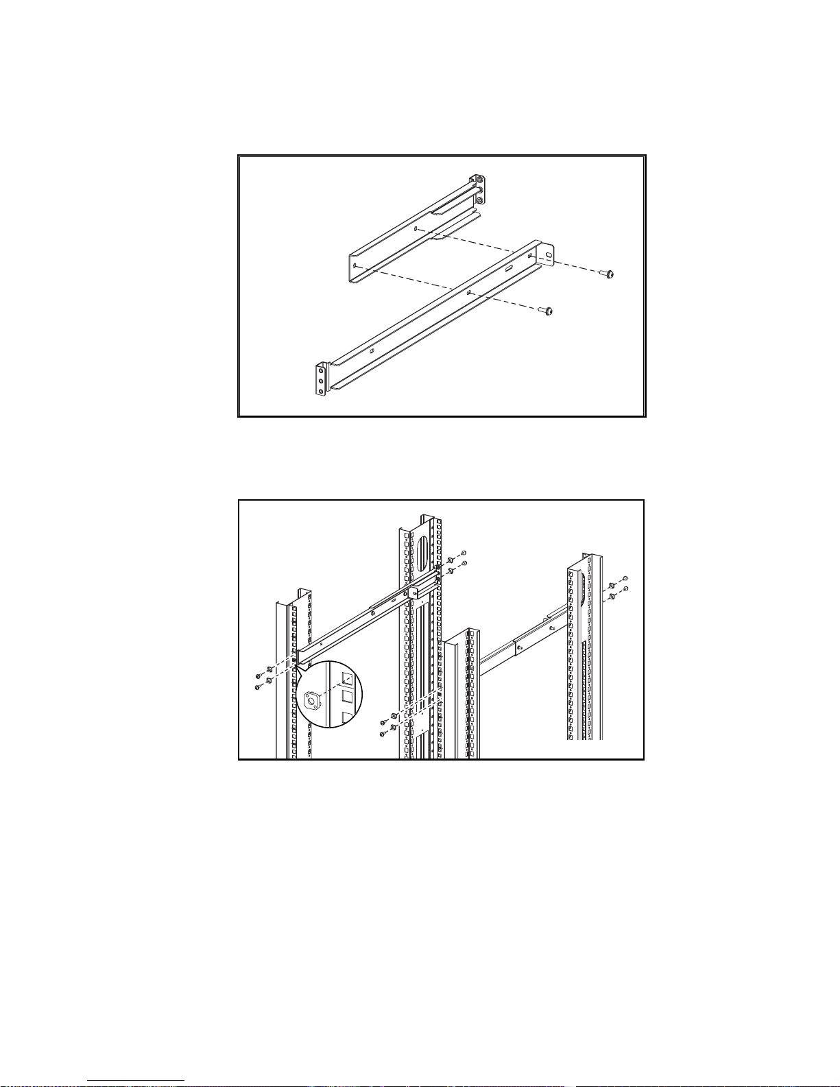
Figure 2-7. Attaching the Slide Brackets, Rack-Front Installation...................... 2-10
Figure 2-8. Attaching the Slide Brackets, Rack-Rear Installation....................... 2-10
Figure 2-9. Securing the Brackets in the Front .................................................. 2-11
Figure 2-10. Securing the Brackets in the Rear.................................................. 2-11
Figure 2-11. Attaching Cable Ties to the Rack Rails ......................................... 2-13
Figure 2-12. Switch Cable Connections ............................................................ 2-13
Figure 3-1. Methods for Managing Information.................................................. 3-3
Figure 3-2. Single-port Management of Switches... . . ........................................... 3-4
Figure 3-3. Front Panel Buttons.......................................................................... 3-6
Figure 3-4. Temperature Sensor Locations on Motherboard .............................. 3-25
Figure 3-5. MIB Tree ....................................................................................... 3-31
Figure 4-1. Navigation Window for a Fibre Channel Network............................. 4-1
Figure 4-2. Fibre Channel Network Window....................................................... 4-3
Figure 5-1. Main Web Tools Screens (Pages)...................................................... 5-2
Figure 5-2. Fabric View Page............................................................................. 5-8
Figure 5-3. Fabric Topology View Page ........................................................... 5-10
Figure 5-4. Fabric Topology View Page ........................................................... 5-11
Figure 5-5. General Switch View Page ............................................................. 5-13
Figure 5-6. Port Detail View Page.................................................................... 5-17
Figure 5-7. Performance View Page ................................................................. 5-21
Figure 5-8. Administrative Functions Page ....................................................... 5-22
Figure 5-9. Telnet Interface Page...................................................................... 5-26
Figure 5-10. Popup Help Dialog Box................................................................ 5-27
Figure 6-1. Fabric with Three Zones................................................................... 6-2
Figure 6-2. Zone Management Example ........................................................... 6-12
Page 10

x StorageWorks Fibre Channel Storage Switch User's Guide
Figure 6-3. Zone Management Example 2 .........................................................6-12
Figure 6-4. aliAdd Command............................................................................6-18
Figure 6-5. aliCreate Command.........................................................................6-18
Figure 6-6. aliDelete Command.........................................................................6-18
Figure 6-7. aliRemove Command......................................................................6-19
Figure 6-8. aliShow Command..........................................................................6-19
Figure 6-9. cfgAdd Command...........................................................................6-20
Figure 6-10. cfgCreate Command......................................................................6-20
Figure 6-11. cfgDelete Command......................................................................6-21
Figure 6-12. cfgRemove Command...................................................................6-21
Figure 6-13. cfgShow Command.......................................................................6-22
Figure 6-14. zoneAdd Command .......................................................................6-23
Figure 6-15. zoneCreate Command....................................................................6-24
Figure 6-16. zoneDelete Command....................................................................6-24
Figure 6-17. zoneRemove Command.................................................................6-24
Figure 6-18. zoneShow Command.....................................................................6-25
Figure 6-19. cfgClear Command........................................................................6-26
Figure 6-20. cfgDisable Command....................................................................6-27
Figure 6-21. cfgEnable Command.....................................................................6-27
Figure 6-22. cfgSave Command ........................................................................6-27
Figure 6-23. cfgShow Command Example.........................................................6-28
Figure B-1. agtcfgset Command Example ...........................................................B-2
Figure B-2. agtcfgShow Command Example ......................................................B-3
Figure B-3. aliasShow Command Example......................................................... B-5
Figure B-4. date Command Example..................................................................B-6
Figure B-5. dateShow Command Example ......................................................... B-7
Figure B-6. errShow Command Example............................................................ B-9
Figure B-7. fabricShow Command Example.......................................................B-9
Figure B-8. fastboot Command Example ..........................................................B-10
Figure B-9. flashDefaultflashDefault Command Example.................................B-11
Figure B-10. flashSet Command Example ........................................................B-16
Figure B-11. flashShow Command Example.....................................................B-22
Figure B-12. h Command Example...................................................................B-26
Figure B-13. help Command Example.............................................................. B-28
Figure B-14. i Command Example ...................................................................B-29
Figure B-15. ifShow Command Example..........................................................B-31
Figure B-16. ipAddrSet Command Example.....................................................B-32
Figure B-17. login Command Example .............................................................B-33
Figure B-18. ipAddrShow Command Example.................................................B-33
Figure B-19. logout Command Example...........................................................B-33
Figure B-20. nsAllShow Command Example....................................................B-34
Figure B-21. nsShow Command Example.........................................................B-34
Figure B-22. passwd Command Example .........................................................B-35
Figure B-23. portDisable Command Example................................................... B-37
Figure B-24. portEnable Command Example....................................................B-38
Figure B-25. portLogclear Command Example.................................................B-38
Page 11

About This Guide xi
Figure B-26. portLogDump Command Example............................................... B-39
Figure B-27. portLogShow Command Example................................................B-40
Figure B-28. portPerfShow Command Example................................................B-45
Figure B-29. portShow Command Example......................................................B-46
Figure B-30. portStatsShow Command Example...............................................B-49
Figure B-31. reboot Command Example...........................................................B-53
Figure B-32. syslogdIp Command Example......................................................B-53
Figure B-33. switchDisable Command Example...............................................B-53
Figure B-34. switchEnable Command Example................................................B-54
Figure B-35. switchName Command Example..................................................B-55
Figure B-36. switchShow Command Example..................................................B-56
Figure B-37. tempShow Command Example ....................................................B-59
Figure B-38. version Command Example .........................................................B-59
Figure B-39. diagHelp Command Example.......................................................B-61
Figure B-40. routeHelp Command Example .....................................................B-61
Figure B-41. centralMemoryTest Command Example.......................................B-62
Figure B-42. crossPortTest Command Example................................................B-64
Figure B-43. portLoopbackTest Command Example.........................................B-66
Figure B-44. portRegTest Command Example..................................................B-68
Figure B-45. ramTest Command Example........................................................B-68
Figure B-46. rdramTest Command Example..................................................... B-69
Figure B-47. spinSilk Command Example 1 .....................................................B-70
Figure B-48. spinSilk Command Example 2 .....................................................B-71
Figure B-49. diagDisablePost Command Example............................................B-72
Figure B-50. diagEnablePost Command Example.............................................B-72
Figure B-51. diagShow Command Example .....................................................B-74
Figure B-52. bcastShow Command Example....................................................B-76
Figure B-53. fspfShow Command Example......................................................B-78
Figure B-54. interfaceShow Command Example...............................................B-80
Figure B-55. LSDbShow Command Example...................................................B-85
Figure B-56. mcastShow Command Example 1 ................................................B-88
Figure B-57. mcastShow Command Example 2 ................................................B-89
Figure B-58. nbrStateShow Command Example ...............................................B-90
Figure B-59. nbrStateShow Command Example ...............................................B-91
Figure B-60. topologyShow Command Example 1............................................B-92
Figure B-61. topologyShow Command Example 2............................................B-93
Figure B-62. uRouteShow Command Example.. . . . . . . . . . ......................................B-95
Figure B-63. licenseHelp Command Example.. . ................................................B-97
Figure B-64. licenseAdd Command Example..... ...............................................B-97
Figure B-65. licenseShow Command Example .................................................B-98
Figure B-66. licenseRemove Command Example ............................................. B-98
List of Tables
Table 1-1 Option Kits.......................................................................................... 1-2
Table 2-1 Universal Mounting Kit Parts............................................................... 2-2
Page 12

xii StorageWorks Fibre Channel Storage Switch User's Guide
Table 2-2 Fiber-optic Cable Specifications .........................................................2-13
Table 2-3 Port LED Status Indicators..................................................................2-14
Table 3-1 Comparison of Managegement Access Methods................................... 3-2
Table 3-2 Front Panel Control Buttons................................................................. 3-6
Table 3-3 Front Panel and Telnet Commands....................................................... 3-8
Table 3-4 Operating Mode Definitions................................................................3-15
Table 3-5 Port Types..........................................................................................3-24
Table 3-6 Module Types ....................................................................................3-24
Table 3-7 Licenses.............................................................................................3-27
Table 3-8 Default Username...............................................................................3-28
Table 3-9 syslog Message Classification............................................................. 3-41
Table 5-1 Fabric Topology Fields.......................................................................5-12
Table 5-2 General Information Fields .. . ..............................................................5-14
Table 5-3 Port LED Status Indicators..................................................................5-15
Table 5-4 Port Detail View Page Fields.............................................................. 5-18
Table 5-5 System Administration Fields.............................................................5-23
Table 6-1 Zoning Commands.............................................................................6-16
Table 6-2 Zone Alias Command Descriptions..................................................... 6-17
Table 6-3 Zone Configuration Command Descriptions........................................6-20
Table 6-4 Zone Command Descriptions.............................................................. 6-23
Table 6-5 Configuration Management Command Descriptions............................6-26
Table A-1 Switch Terminology ...........................................................................A-1
Table B-1 agtcfgShow Field Command Descriptions...........................................B-4
Table B-2 aliasShow Command Field Descriptions..............................................B-5
Table B-3 DateShow Command Field Descriptions .............................................B-7
Table B-4 fabricShow Command Field Descriptions..........................................B-10
Table B-5 flashSet Command Field Descriptions...............................................B-17
Table B-6 flashShow Command Field Descriptions...........................................B-23
Table B-7 i Command Field Descriptions..........................................................B-30
Table B-8 ipAddrSet Command Descriptions ....................................................B-32
Table B-9 portlogShow Command Field Descriptions........................................B-41
Table B-10 portShow Command Field Descriptions...........................................B-47
Table B-11 portStatsShow Command Field Descriptions ...................................B-50
Table B-12 switchShow Command Field Descriptions.......................................B-57
Table B-13 version Command Field Descriptions..............................................B-60
Table B-14 portloopbackTest Command Field Descriptions ...............................B-67
Table B-15 diagShow command field descriptions.............................................B-75
Table B-16 bcastShow Bitmap Field Descriptions.............................................. B-77
Table B-17 fspfShow Command Field Descriptions...........................................B-78
Table B-18 interfaceShow Command Field Descriptions ...................................B-81
Table B-19 LSDbShow Command Field Descriptions........................................B-86
Table B-20 mcastShow Bitmap Field Descriptions.............................................B-89
Table B-21 nbrStateShow Command Field Descriptions....................................B-91
Table B-22 topologyShow Command Field Descriptions ...................................B-94
Table B-23 uRouteShow Command Descriptions...............................................B-96
Page 13

About This Guide
This guide is designed to be used as step-by-step instructions for installation
and as a reference for operation, troubleshooting, and future upgrades.
Text Conventions
This document uses the following conventions to distinguish elements of text:
Keys Keys appear in boldface. A plus sign (+) between
two keys indicates that they should be pressed
simultaneously.
USER INPUT
User input appears in a different typefac e and in
uppercase.
Type When you are instructed to type information, type
the information without pressing the Enter key.
Enter When you are instructed to enter infor matio n, type
the information and then press the Enter key.
Symbols in Text
These symbols may be found in the text of this guide. They have the following
meanings.
WARNING:
Text set off in this manner indicates that failure to follow directions
in thewarning could result in bodily harm or loss of life.
Page 14

xiv StorageWorks Fibre Channel Storage Switch User's Guide
CAUTION:
Text set off in this manner indicates that failure to follow directions
could result in damage to equipment or loss of information.
IMPORTANT:
Text set off in this manner presents clarifying information or specific
instructions.
NOTE:
Text set off in this manner presents commentary, sidelights,or interesting points
of information.
Symbols on Equipment
These icons may be located on equipment in areas where hazardous conditions
may exist.
Any surface or area of the equipment marked with these symbols
indicates the presence of electrical shockhazards. Enclosed area
contains no operator serviceable parts.
WARNING:
To reduce the risk of injury from electrical shock hazards,
do not open this enclosure.
Any RJ-45 receptacle marked withthese symbols indicates a Network
Interface Connection.
WARNING:
To reduce the risk of electrical shock, fire, or damage to
the equipment, do not plug telephone or telecommunications
connectors into this receptacle.
Any surface or area of the equipment marked with these symbols
indicates the presence of a hot surface or hot component. If this
surface is contacted, the potential for injury exists.
WARNING:
To reduce the risk of injury from a hot component, allow
the surface to cool beforetouching.
Page 15

About This Guide xv
Power Supplies or Systems marked with these symbols
indicate the equipment is supplied by multiple sources of
power.
WARNING:
To reduce the risk of injury from electrical shock,
remove all power cords to completely disconnect power from
the system.
Rack Stability
WARNING:
To reduce the risk of personal injury or damage to the equipment,
be sure that:
■
The leveling jacks are extended to the floor.
■
The full weight of the rack rests on the leveling jacks.
■
The stabilizing feet are attached to the rack if it is a single rack
installations.
■
The racks are coupled together in multiple rack installations.
■
A rack may become unstable if more than one componentis extended for
any reason.Extend only one componentat a time.
Getting Help
If you have a problem and have exhausted the information in this guide, you
can get further information and other help in the following locations.
Compaq Technical Support
You are entitled to free hardware technical telephone support for your product
for as long you own the product. A technical support specialist will help you
diagnose the problem or guide you to the next step in the warranty process.
In North America, call the Compaq Technical Phone Support Center at
1-800-OK-COMPAQ
1
. This service is available 24 hours a day, 7 days a week.
1
For continuous quality improvement, calls may be recorded or monitored.
Page 16

xvi StorageWorks Fibre Channel Storage Switch User's Guide
Outside North America, call the nearest Compaq Technical Support Phone
Center. Telephone numbers for world wide Technical Support Centers are
listed on the Compaq website. Access the Compaq website by logging on to
the Internet at
http://www.compaq.com
.
Be sure to have the following information available before you call Compaq:
■
Technical support registration number (if applicable)
■
Product serial number (s)
■
Product model name(s) and numbers(s )
■
Applicable error messages
■
Add-on boards or hardware
■
Third- part y hardw are o r softw are
■
Operating system type and revision level
■
Detailed, specific questions
Compaq Website
The Compaq website has information on this product as well as the latest
drivers and Flash ROM images. You can access the Compaq website by
logging on to the Internet at
http://www.compaq.com
.
Compaq Authorized Reseller
For the name of your nearest Compaq Authorized Reseller:
■
In the United States, call 1-800-345-1518.
■
In Canada, call 1-800-263-5868.
■
Elsewhere, see the Compaq website for locations and telephone
numbers.
Page 17

Chapter
1
Introduction
Option Kits
The StorageWorks Fibre Channel Storage Switch is a key component of the
Enterprise Network Storage Area (ENSA) implementation. The Switch is used
to connect network servers with storage devices, such as Compaq’s
RA8000/ESA12000 HSG80 RAID Array Storage Subsystems, to create a
Storage Are a Netwo r k (SAN). There are two Switch Option Kits (Mo del s), an
8-port model and a 16-port model. The 8-port model contains four dual-port
interface cards; the 16-port model has eight interfaced card installed on the
motherboard.
NOTE:
Note: Zoning, Cascading, FL_ports, SES, and Copper Media are not fully
supported by Compaq as of April 1999. However, the software bundle that
enables these features is included in the software package with this Switch and
is provided at no additional cost so that customers may have the opportunity to
become familiar with these advanced SAN functions. Compaq will support many
of these and other SAN functions in the future. Contact your Compaq Authorized
Reseller or Compaq Account Representative for specific information on these
features.
Page 18

1-2 StorageWorks Fibre Channel Storage Switch User's Guide
Table 1-1
Option Kits
Model Part Number
8-port Fibre Channel Switch, rack mount kit, software/doc.
kit, no GBICs
DS-DSGGA-AA
380591-B21
16-port Fibre Channel Switch, rack mount kit,
software/doc. kit, no GBICs
DS-DSGGA-AB
380578-B21
The Switch supports up to 16 fibre channel ports and consists of a
motherboard, processor board, connectors for supporting up to 8 dual-port
interface cards, and software for building and managing a Fibre Channel
Fabric. The primary function of a Fabric is to receive frames from a source
N_Port (host bus fibre channel adapter or fibre channel storage) and route the
frames to the destination N_Port whose address identifier is specified in the
frame.
Front Panel Features
0123 4567891011121314
15
6
1 2 3
4
5
SHR-1206
Figure 1-1. Storage Switch Front Panel
1
Fibre Channel Port: Connects the Switch to the Fabric.
2
RJ45 Ethernet Connector: Connects the Switch to the network for out-of-
band management of the Switch.
Page 19

Introduction 1-3
3 Front Panel Display: Shows menu selections. Used to configure and
manaage the Switch using the front panel controls.
4
Power Connector: Connects the Switch to the power source.
5
ON/OFF Switch: Turns the Swi tc h ON and Off.
6
Front Panel Controls: The front panel controls are used to navigate
through the built-in menus and to make menu selections.
Page 20

Page 21

Chapter
2
Installing the Switch
Installation Summary
To install the Switch you have to perform the following steps:
■
Unpack the shipping container
■
Select an operating location
■
Select a Switch mounting method
■
Install the Gigabit Interface Converter (GBIC) modules (ordered
separately)
■
Connect cables to the Switch
■
Turn on the power to the Switch
■
Enter the IP address.
Package Contents
Make sure the follo w ing items are included in the shipment:
■
A 16-port Fibre Channel Switch (380578-B21) or an 8-port Fibre
Channel Switch (380591-B21)
■
Two ac power cords: one for rack mounting the Swi tch; one for table
top use
■
Interface cards (already installed in the Switch)
Page 22

2-2 StorageWorks Fibre Channel Storage Switch User's Guide
■
A software and documentation kit
■
An Installation Kit that includes rubber mounting feet
■
A Universal Mounting Kit for mounting the Switch in an equipment
rack. Table 2-1 describes the kit contents, while Figure 2-1 illustrates
the parts.
Table 2-1
Universal Mounting Kit Parts
Part Description
Part Number
Quantity
Slide bracket
74–60352–01
2
Mount i ng brac k et
74–60354–01
2
Extender bracke t
74–60353–01
2
Screw, SEMS, 10–32x9/32 12–21368–04
4
Screw, SEMS, 10–32x5/8
12–21368–02
16
Push mount cable ti e
90–11456–01
2
Clip nut
90–07786–00
4
Alignment w asher
74–60363–01
8
Installation Guide
EK–GGAAB–IG
1
Mounting template
EK–GGAAB–RT
1
Page 23

Installing the Switch 2-3
1
2
3
4
SHR-1383
Mounting bracket; Extend e r bra c ke t; Slide bracket; Hardware bag
Figure 2-1. Univ ersal Mounting Kit Parts
Selecting an Operating Location
The Switch should be located in a secure or limited-access place to control use
of the Switch front panel controls, and to ensure that cable connections are not
compromised. The operating location you select for the Switch must meet
cooling air requirements and power requirements.
Cooling Air Requirements
Cooling air is drawn into the Switch chassis by the power supply fan and by
two other fans mounted on the rear of the chassis; the air is expelled through
vents in the front of the chassis. The combined air flow through the Switch is
75 cubic feet per minute (cfpm), and nominal bulk flow of 15 cfpm.
CAUTION:
Do not block the front or rear air vents . The Switch must have free
access to ambient air for cooling.
Page 24

2-4 StorageWorks Fibre Channel Storage Switch User's Guide
Power Requirements
You connect the ac power cord to a switched connector on the bottom right
side of the Switch front panel. The ac power source must meet thes e
requirements:
■
A properly–wired, earth–grounded ac outlet
■
Voltage capability of 90–134 Vac or 180–257 Vac, and IEC 801-5 surge
voltage
■
Input voltage frequency of 50–60 Hz
■
Power capability of 219 watts, maximum.
The Switch has an autoranging power supply that automatically accepts
voltages within its range. There is no provision for surge protection built
into the Switch power supply so the ac source should include provisions to
assure clean ac power.
Selecting a Switch Mou ntin g Metho d
The Switch can be placed on a table top or other surface, or it can be mounted
in an equip ment rack.
Placing the Switch on a Surface (Table-top
Mounting)
You can set the Switch on a surface, such as a table top, and operate it from
that location. Although adhesive rubber feet are included in the Installation
Kit, they are not necessary for proper or safe operation of the Switch. If you
want to install the rubber feet, perform these steps:
■
Use the alcohol wipes to clean the depression in each corner of the
bottom of the chass is ; allow th e alcohol to dry.
■
Remove the rubber feet from the sheet and insert one in each depression.
■
Press the rubber feet in place firmly.
Page 25

Installing the Switch 2-5
For table-top mounting continue the installation procedure with Installing the
GBIC Modules.
NOTE: If you attach rubber feet, you have to remov e them before you can install the
Switch in a 19- inc h eq ui pm e nt rac k.
Mounting the Switch in an Equipment Rack
You can install the Switch in a RETMA 41U or 42U rack, in a Compaq rack,
or in a metric SW600 rack. Observe the following guidelines:
■
When you install the Switch in a closed or multi–rack assembly, be sure
the air temperature measured at the Switch front panel does not exceed
40° C (104° F).
■
Make sure the air flow to the Switch is at least 300 cfpm.
■
Verify that when the Switch is installed it does not unbalance the rack or
exceed the rack mechanical limits, both with the slide brackets secured
and with the slide brackets fully extended.
■
Verify that the supply circuit, the line fuse, and the wire size are
appropriate for the service.
■
Verify that all the other equipment installed in the rack has a reliable
ground connection; do not rely on connection to a branch circuit, such as
a power strip.
■
Route and support the power cord to ensure that the Switch moves
freely on the slide brackets without crimping or chafing the power cord,
or interfering with other equipment and cables installed in the rack.
Before you install the Switch in the rack you must attach mounting brackets to
the rack rails. Where you attach the mounting brackets vertically in the rack
depends on your installation, i.e., what other equipment is mounted in the rack
along with the Switch. The only tool you need is a Number 2 Phillips
screwdriver. Perform the applicable procedure from the following subsections.
Attaching Mounting Brackets in a
RETMA 41U Rac k
You mount the Switch in this rack from the front of the rack only. Perform the
following steps:
1.
Position the mounting template against the front and rear vertical rails
(Figure 2–2), first on one side of the cabinet and then on the other side;
make sure the template is parallel from front–to–rear.
Page 26

2-6 StorageWorks Fibre Channel Storage Switch User's Guide
IMPORTANT: The template front should be positio ned against the front rail, while the
template rear should be positioned against the rear rail.
SHR-1384
Figure 2-2. Positioning the Mounting Template
2. Pencil–mark the mounting bracket holes on each side of the rack
with an M.
3. Slide a clip nut over the marked hole on each rear rail (Figure 2–3).
4. Attach a mounting bracket to the rails on each side of the rack and
secure each bracket with three 10–32x5/8 SEMS screws; tighten the
screws at the front before you tighten the one at the rear.
5. Go to the section entitled Attach ing the S lide Brackets to the Sw itch.
Page 27

Installing the Switch 2-7
2
1
1
SHR-1380
2
Mounting bracket; Clip nut
Figure 2-3. Installing the Mounting Brackets in a RETMA 41U Rack
Attaching Mounting Brackets in a RETMA 42U or
Compaq Rack
You can mount the Switch in this rack from either the front or the rear of the
rack. Perform the following steps:
1. Position the mounting template against the front and rear vertical rails
(Figure 2–2), first on one side of the cabinet and then on the other side;
make sure the template is parallel from front–to–rear.
IMPORTANT:
In a rack –front installation the template front should b e positioned against
the front rail; in a rack–rear installation the template front s hould be positioned against
the rear rail.
2. Pencil–mark the mounting bracket holes on each side of the rack with
an M.
3. Connect an extender bracket to each mounting bracket using two SEMS
10-32x5/8 screws (Figure 2–4); just finger–tighten the screws.
Page 28
2-8 StorageWorks Fibre Channel Storage Switch User's Guide
SHR-1381
Figure 2-4. Connecting an Extender Bracket to a Mounting Brack e t
4. Insert an alignmen t washer into each of the eight rail ho les mark ed M
(Figure 2–5).
SHR-1382
Figure 2-5. Installi ng the Mounting Brackets in a RETMA 42U or Compaq
Classic Rack
5. Attach each mounting bracket to the rack rails by inserting SEMS
10-32x5/8 screws through the alignment washers into the bracket holes;
tighten all the screws.
6. Tighten the four screws that connect the extender brackets to the
mounting brackets.
Page 29

Installing the Switch 2-9
IMPORTANT: These screws must be fully tightened to ensure to strength of the extended
bracket.
7. Go to the subsection entitled Attaching the Slide Brackets to the Switch.
Attaching Mounting Brackets in a Metric Rack
You mount the Switch in this rack from the front of the rack only. Perform the
following steps:
1. Position the mounting template against the front and rear vertical rails
(Figure 2–2), first on one side of the cabinet and then on the other side;
make sure the template is parallel from front–to–rear.
IMPORTANT: The template front should be positio ned against the front rail, while the
template rear should be positioned against the rear rail.
2. Pencil–mark the mounting bracket holes on each side of the rack with an
M.
3. Slide a clip nut over each hole identified as a clip nut mounting hole
(Figure 2–6).
2
1
1
SHR-1390
2
Mounting bracket; Clip nut
Figure 2-6. Installing the Mounting Brackets in a Metric Rack
4. Attach a mounting bracket to the rails on each side of the rack and
secure each bracket with 10–32x5/8 SEMS screws.
5. Go to th e sub section entitl ed Attaching the Slide Brackets to the Switch.
Page 30

2-10 StorageWorks Fibre Channel Storage Switch User's Guide
Attaching the Slide Brackets to the Switch
You attach the slide brackets to the Switch using different bracket mounting
holes for a rack-front installation than for a rack-rear installation. Use Figure
2–7 or Figure 2–8 to guide you in installing the slide brackets on the Switch;
attach each bracket with two SEMS 10–32 x 9/32 pan–head screws.
CAUTION:
Make s ure you use the right screws. If you use screws longer than
9/32", you can damage the Switch.
SHR-1385
Figure 2-7. Attaching the Slide Brackets, Rack-Front Installation
SHR-1389
Figure 2-8. Attaching the Slide Brackets, Rack-Rear Installation
Page 31

Installing the Switch 2-11
Installing the Switch in the Rack
To install the Switch in the rack you have to lift up the Switch and insert the
slide brackets into the mounting brackets.
CAUTION:
Make s ure you keep the Switch parallel to the floor when yo u insert
the slide brackets into the mounting brac kets; you could damage the br ackets if
you tilt the Switch.
Slide the Switch all the way into the mounting brackets and secure the slide
brackets in the mounting brackets with four SEMS 10–32 x 5/8 pan–head
screws (Figures 2–9 and 2–10).
SHR-1386
Figure 2-9. Securing the Brackets in the Front
SHR-1387
Figure 2-10. Secur ing the Brackets in t he Rear
Page 32

2-12 StorageWorks Fibre Channel Storage Switch User's Guide
Installing GBIC Modules
Each interface card installed in the Switch has two G_Ports. A GBIC module
must be installed in each G_Port in order to use that port. Perform the
following steps to install a GBIC module.
CAUTION:
The GBIC modules contain static sensitive com ponents. Use ES D
precautions when handling this card.
CAUTION:
When you insert the GBIC module in the next step, do not force the
module if you feel resistance.
1. Insert the GBIC module into the G_Port. The module is keyed and you
can insert it only one way; if you feel resistance after you have inserted
the module about an inch into the G_Port, you have oriented it
incorrectly. When it is oriented correctly, be sure the locking bar on the
front of the module is positioned to the right.
2. W hen the GBIC module is fully inserted lock it in place by moving the
locking bar to the left.
3. Insert a rubber protective plug over the module fiber–optic connectors.
4. Re peat the procedure for each GBIC module to be installed.
Connecting Cables to the Switch
All cables connect at the front of the Switch. Install two push–mount cable ties
so you can route the power and data cables along the rack rails (Figure 2-11).
SHR-1388
Page 33

Installing the Switch 2-13
Figure 2-11. Attaching Cable Ties to the Rack Rails
Connecting the StorageWorks Subsystem and the
Host to the Switch
The StorageWorks subsystem and the host connect to the Switch by fiber–
optic cables that have the specifications shown in Table 2–2.
Table 2-2
Fiber-optic Cable Specifications
Item Specific ation
Cable type
Multimode fiber, 50 µm or 62.5 µm core
diameter; 125 µm cladding diameter
Connector type Duplex SC plug connectors
Maximum cable le ng th
500 meters (1641 feet) 50 µm/125 µm
200 meters (656 feet) 62.5/µm 125 µm
GBIC m o dule type
Shortwave (770–850) µm, without open–
fiber control
The SC connectors, and (Figure 2-12), are indexed and must be inserted
into the GBIC module connectors properly. Remove the protective cover from
the GBIC connector and make sure the fiber surface of all the connectors are
clean and free of dust or debris before mating the connectors.
0
1
2
3
4
5
6
7
8
9
10
11
12
13
14
15
1
2
3
4
5
6
7
SHR-1309
Figure 2-12. Switc h Cable Connections
Page 34

2-14 StorageWorks Fibre Channel Storage Switch User's Guide
Connecting an Ethernet Network to the Switch
Connect an Ethernet 10BaseT network to the Switch by plugging in the
Ethernet cable at the RJ-45 connector .
Connecting the Power Cable to the Switch
Connect the ac power cable to the Switch ac connector .
Turn on the Power to the Switch
Turn on the ac power switch . The Switch runs the power–on self test
(POST). The front panel display shows the tests performed in serial fashion:
■
Memory tes t
■
Port register test
■
Central memory test
■
Port loop-back test.
When ea ch test comp letes suc cessfu lly, the mes s age “Pass ed” app ears on the
display. When all the tests have been completed the display returns to the
normal dark condition, and the Port LEDs show a steady green light. Refer to
Table 2-2 for the meaning of the different LED states.
If the POST encounters errors, the last error discovered is retained on the front
panel displa y a fte r t he POST is com plet e. If the POST is comp lete d
successfully, the Switch is ready to operate.
Table 2-3
Port LED Status Indicators
Port’s LED Port’ s LED
No light showing
No light or signal ca rrier (no module, no
cable) for media inter face LEDs.
Steady yellow Receiving light or signal carrier, but not yet
online.
Slow yellow
Disable d (result of diagnostics or
portDisable command). Flashes every 2
seconds.
Page 35

Installing the Switch 2-15
Fast yellow Error, fault with po rt. Flashes every 1/2
second.
Steady green Online (connected with external d evice over
cable)
Slow green Online, but segme nted (loopback cable or
incompatible Switch) flashes every 2
seconds.
Fast green
Internal loopback (diagnostic). Flashes
every 1/2 second.
Flickering green Online and frames flowing through port.
Page 36

2-16 StorageWorks Fibre Channel Storage Switch User's Guide
Enter the IP Address of Your Switch
To enter an IP address you use the front panel display and the four buttons
under the display. (Refer to Chapter 3 for more information on managing the
Switch using the front panel.) After the Switch successfully completes POST,
proceed as follows:
1. Press the down-arrow button (far left button). The display shown
Configuration Menu.
2. Press the left-arrow but ton, far righ t button. This button is the enter
button. The display shows IP Address.
3. Press the enter button again. Use the right-arrow button to scroll through
the IP address. After you have selected “IP Address”, the up-arrow and
down-arrow buttons allow you to increment and decrement each numbic
entry.
Page 37

Chapter
3
Managing the Switch
Switch Management Overview
This chapter contains general information and examples on managing and
monitoring the Sw itch. Th is ch apter dis cu s ses:
■
Comparing Switch Management Methods
■
Managing the Switch Using the Front Panel Controls
■
Managing Via Telnet
■
Managing with SNMP
■
syslog Daem on
■
Managing the Switch using StorageWorks Command Console (refer to
Chapter 4 for an introduction to StorageWorks Command Console
software).
■
Managin g the Switch Over the Web (Refer to Cha p ter 5)
Page 38

3-2 StorageWorks Fibre Channel Storage Switch User's Guide
Comparing Switch Management Access
Methods
There are several access methods for managing a Switch. Table 3-1
summarizes the different manag em en t access methods.
Table 3-1
Comparison of Managegement Access Methods
Method Description Local In-Band
(Fibre
Channel)
Out-of-band
(Ethernet)
Front panel
controls
Managed through
control located
on the Switch
Yes No No
Telnet
commands
Managed
remotely using
Telnet
commands
No Yes Yes
Managing with
SNMP
Managed
remotely using
Simple Network
Management
Protocol (SNMP)
No Yes Yes
Web-based
management
Managed
remotely though
web
No Yes Yes
Managing with
Command
Console
Managed
remotely though
Command
Console
No Yes Yes
NOTE: An advanced set of controls and displays are available using a Telnet connection
for testing and debugging purposes. Before a Telnet connection can be established the
Switch must have an IP address assigned to it, use the front panel buttons to assign an IP
address.
To reset a Switch to factory default values, use the Reset to Default command
described in Reset to Default. Before changing any factory default settings,
become familiar with the operations described in this chapter including both
the Switch’s functions and interactiv e charac teristics.
Page 39

Managing the Switch 3-3
Figure 3-1 shows the various methods and communication paths for accessing
Switch management information. (StorageWorks Comand Console GUI
interface is not shown.)
Management Information
Front-Panel SES Device SNMP Agent
Telnet
Web
SNMP HTTP
UDP TCP
FCP
IP Over Ethernet
Push Buttons
LED Display
Fibre Channel (In Band) Ethernet (Out-of-Band)
FC-IP
SHR-1208
Figure 3-1. Methods for Managing Information
Page 40

3-4 StorageWorks Fibre Channel Storage Switch User's Guide
Fabric Management through a Single
Ethernet Port
Multiple Compaq Storage Switches can be managed through a single IP
connecti o n to one of the Switc hes u sing Telnet se r vice s, We b Tools o r SNMP
commands, shown in Figure 3-2. Each Switch supports a 10bT Ethernet
connection that has generally been the link for IP services. There is a second
IP connection, the Fibre Channel IP or in-band support which is also available
for use when managing a Switch.
Ethernet
Switch 1
Switch 2
Switch 3
FC IP
FC IP
Management
Station
Figure 3-2. Single-port Management of Switches
At this point there are no Host Bus Adapters (HBAs) that can initiate in-band
fibre channel IP connections. For that reason, it is necessary to have at least
one Ethernet connection into the Fabric. From that one entry point, it is
possible to manage the remaining Switches in the Fabric using in-band IP
services.
The management workstation, which runs a browser, a Telnet session or
SNMP, will need to be able to add ress t he Switc h that has an Ethern et
connection. This means that the management workstation and the Ethernet IP
address of the a Switch need to be in the same subnet. In addition, the
manage ment station must either hav e a s tatic route to the FC IP su bnet, or the
Switch must be the default gateway for the management workstation. This will
allow the management station to direct IP to or through the Switch.
Page 41

Managing the Switch 3-5
The Switches not connected to the Ethernet must have their default gateways
set to the Fibre Channel IP address of the Switch connected to the Ethernet.
Also, these Switches must have their FC IP addresses in a different subnet
from the Ethernet IP addresses of the management station. Lastly, the FC IP
addresses of all Switches must be in the same subnet. Example settings follow:
Management
Station
Switch 1Switch 2Switch 3
Ethernet IP
Address
192.168.1.09 192.168.1.10 204.1.1.11 204.1.1.12
FC IP Address 192.168.65.09 192.168.65.10 192.168.65.11 192.168.65.12
Default
Gateway
192.168.65.10 (any) 192.168.65.10 192.168.65.10
The effect of this special connectivity is that the route to all switches will be
through the single Switch with the Ethernet connection. The route back to the
workstation from the other Switches will also be though that initial Switch.
The initial Switch, which has both Ethernet and FC IP capability, will act as a
“bridge” in that it will route between Ethernet and FC IP to send the traffic to
the right place with the right protocol.
Managing Using the Front Panel Buttons
Figure 3-1 shows the front panel buttons, they allow you to select the
following menus:
■
Configuration Menu
■
Operation Menu
■
Status Menu
■
Test Menu.
Page 42

3-6 StorageWorks Fibre Channel Storage Switch User's Guide
SHR-1209
1
2 3 4 5
6
Figure 3-3. Front Panel Buttons
Table 3-2 lists the primary control button functions. Button function changes
depending on the menu level. Buttons either control navigating through the
menus or incrementing/decrementing numeric values.
Table 3-2
Front Panel Control Buttons
Item Number Control Button Description
2 <Down> <Down> scrolls down the command list, or if
the user is changing a numeric display, it
decrements the displayed value.
3 <Up> <Up> scrolls up the command list, or if the
user is changing a numeric display, pressing
this button increments the numeric value.
4 <Tab/Esc>
<Tab/Esc> tabs through multiple options.
When displaying a menu item, pressing the
<Tab/Esc> button reverses through previous
commands and, if pressed repeatedly, turns
off the front panel display.
5<Enter>
<Enter> accepts the input and executes the
selected function. To abort an entry, pressing
<Tab/Esc> navigates to the previous item.
When entering a number, the <Up> and <Down> buttons start in the slow
mode and change to, if either button is held down, the fast mode. Most
number s go to a maxi mu m of 255; f or a large nu mb er, it may be faster to u s e
the <Down> button.
Page 43

Managing the Switch 3-7
Activating Menu Display
The Switch’s front panel display is normally not illuminated. Pressing any
front panel buttons activates the display: If no command is issued, the display
turns off after 30 seconds
Menus
The menus are controlled using front panel buttons. From the initial display,
users can navigate to commands and configure the Switch. The following
menus are discussed:
■
Configuration Menu
■
Operation Menu
■
Status Menu
■
Test Menu.
Page 44

3-8 StorageWorks Fibre Channel Storage Switch User's Guide
Table 3-3 shows the front panel commands and their equivalent Telnet
command.
NOTE: For most applications default values should be used.
Table 3-3
Front Panel and Telnet Commands
Menu F
RONT PANEL
T
ELNET COMMAND
D
EFAULT
Conjfiguration
Ethernet IP
Address
ipAddrSet 192.168.90.x
Ethernet
Subnetmask
ipAddrSet none
Fibre Channel IP
Address
ipAddrSet 192.168.91.1
Fibre Channel
Subnetmask
ipAddrSet
Gateway
Address
ipAddrSet none
Domain flashSet 1
BB_credit flashSet
16 (G_Port)
0 (FL_Port)
R_A_TOV flashSet 10000
E_D_TOV flashSet 2000
Operating Mode flashSet 0
VC Link Ctl flashSet 0
VC Class 2 flashSet 2
VC Class 3 flashSet 3
VC Multicast flashSet 7
VC Priorities flashSet 0,1,2,2,2,2,3,3
Alternate
BB_credit
flashSet 0
Open/Opened
BB_credit
flashSet 4
Frame Collection flashSet 4
Reset to Default flashDefault Piling
continued
Page 45

Managing the Switch 3-9
Table 3-3
Front Panel and Telnet Commands
continued
Menu F
RONT PANEL
T
ELNET COMMAND
D
EFAULT
Switch Offline SwitchDisable N/A
Operation Switch Online SwitchEnable N/A
Port Disable
portDisable
<portno>
N/A
Port Enable
portEnable
<portno>
N/A
Close Telnet
Session
exit N/A
Reboot reboot N/A
Status Switch Name switchShow N/A
Worldwide Name switchShow N/A
Firmware
Version
version N/A
Current Date date N/A
Booted At dateShow N/A
Firmware Date dateShow N/A
Flash Date dateShow N/A
Boot Prom Date dateShow N/A
Port Type switchShow N/A
Module Type switchShow N/A
Port Throughput portPerfShow N/A
Temperature tempShow N/A
Error Log errShow N/A
License licenseShow N/A
Test Switch Offline SwitchDisable N/A
Switch Online SwitchEnable N/A
Memory Test ramTest N/A
continued
Page 46

3-10 StorageWorks Fibre Channel Storage Switch User's Guide
Table 3-3
Front Panel and Telnet Commands
continued
Menu F
RONT PANEL
T
ELNET COMMAND
D
EFAULT
Port Register
Test
portRegTest N/A
Central Memory
Test
centralMemoryTest N/A
RDRAM Test rdramTest N/A
Port Loopback
Test
portLoopbackTest N/A
Cross Port Test crossPortTest N/A
Spin Silk Test spinSilk N/A
Display Test N/A N/A
Push Button Test N/A N/A
Configuration Menu
You configure the Switch using the Configuration Menu. Pressing <Enter>
while in the Configuration Menu selects the option to choose
commands:
IMPORTANT:
After changing any IP address from the following menus from the front
panel or Telnet, you must reboot the Switch for the changes to take effect.
Ethernet IP Address
Pressing <Enter >, while Ethernet IP address is selected, displays the
Switch’s Ethernet IP address:
Ethernet IP Address
10. 00. 00. 10
The Switch’s default IP address, as shown, is a temporary address der ive d
from the Switch’s WWN. Enter a valid IP address.
NOTE: The IP address must have been previously installed using the front panel controls.
Consult with the your network system administrator for the Switch’s assigned IP address.
Only one Telnet session is allowed at a time.
Page 47

Managing the Switch 3-11
To enter an IP address:
1. Use <Up> and <Down> to increment or decrement the displayed value.
The underlined cursor indicates the numbers to modify.
When entering a number, <Up> and <Down> start in the slow mode and move
to the fas t mo de if the bu tton is held down. The numbers go to a maximum of
255 and wraps to zero; for a large number, it may be faster to use the <Down>
button.
2. After entering a number, press <Tab/Esc> to move the cursor to modify
the next field.
3. After setting the IP address, pressing <Enter> stores the value.
Ethernet Subnetmask
Pressing <Enter >, while Ethernet Subnetmask is selected, displays:
Ethernet Subnetmask
none
The default subnet mask value is none. Refer to the network administrator for
the appropriate subnet mask.
Enter the Switch’s subnet address by using <Up> and <Down> to increment or
decrement the displayed value. The numbers with the underline cursor is the
group to modify.
Fibre Channel IP Address
Pressing <Enter >, while Fibre Channel IP address is selected ,
displays:
Fibre Channel IP Address
0. 0. 0. 0
The default Fibre Channel IP address is 0.0.0.0, as shown in the example.
Entering a valid non-zero IP address allows the Switch to transfer IP over the
Fibre Channel and the ability to manage all other switches connected to the
Fabric. All Switches must have Ethernet IP addresses on a different subnet
than their FC IP addresses. The FC IP addresses of all Switches must be on the
same subnet.
To update the Fibre Channel ’s IP addre ss:
Page 48

3-12 StorageWorks Fibre Channel Storage Switch User's Guide
4. Use <Up> and <Down> to increment or decrement the displayed value.
The underlined cursor indicates the numbers to modify.
5. After entering a number, press <Tab/Esc> to move the cursor to modify
the next field.
6. After setting the Fibre Channel’s IP address, pressing <Enter> stores the
value.
Fibre Channel Subnetmask
Pressing <Enter >, while Fibre Channel Subnetmask is selected,
displays:
Fibre Channel Subnetmask
none
The default subnetmask value is none, as shown in the example. Consult your
network administrator for the approp ri ate subn et mask .
Enter the Switch’s Fiber Channel Subnet m ask by using <Up> and <Down> to
increment or decrement the displayed value.
Gateway Address
Pressing <Enter >, while Gateway address is se lected, displays:
Gateway Address
0. 0. 0. 0
The default gateway address is shown above. You must enter a valid gateway
address, if required.
To enter the gateway address:
1. Use <Up> and <Down> to increment or decrement the displayed value.
The underlined cursor indicates the numbers to modify.
2. After entering a number, press <Tab/Esc> to move the cursor to modify
the next field.
3. After setting the gateway address, pressing <Enter> stores the value.
Page 49

Managing the Switch 3-13
Domain
Pressing <Enter >, while Domain is se lected, displays:
Domain
1
The domain number uniquely identifies the Switch in a Fabric. This Switch ID
is normally automatically assigned by the Switch and may be any value
between 0 and 31. You may also assign the initial domain number manually.
The Switch with the lowest initial domain will become the master Switch and
control the configuration.
BB_credit
Pressing <Enter >, while BB_credit is se lected, displays:
BB_credit
16
The number represents the number of buffers, from 1 to 16, available to the
host. The default for G_Port cards is 16. The BB_credit for FL_Port cards is 0.
For a complete description of buffer-to-buffer credit, refer to the industry
specification Fibre Channel Physical and Signalling Interface (FC-PH).
R_A_TOV
Pressing <Enter >, while R_A_TOV is selected , displays:
R_A_TOV
10000
Resource Allocation Time Out Value (R_A_TOV) is adjustable in 1-second
increments using front panel controls, but its value is displayed in
milliseconds. This variable works with the variable E_D_TOV to determine
the Switch’s actions when presented with an error condition. Allocated circuit
resources with detected errors are not released until the time value has expired.
If the condition is resolved prior to the timing out, the internal time out clock
resets and waits for the next error condition. The range is 1 to 120 seconds.
NOTE: The set value must be larger than the set value for the Error Detect Time Out Value
Page 50

3-14 StorageWorks Fibre Channel Storage Switch User's Guide
E_D_TOV
Pressing <Enter >, while E_D_TOV is se lected, displays:
E_D_TOV
2000
E_D_TOV (Error Detect Time Out Value) is adjustable in 1-second
increments using the front panel controls, but its value is displayed in
milliseconds.
NOTE: Use the flashSet command during a Telnet session to set the E_D_TOV or
R_A_TOV value (in milliseconds) for values other than whole seconds.
This timer is used to flag a potential error condition when an expected
response is not received (an acknowledgment or reply in response to packet
receipt, for example) within the set time limit. If the time for an expected
response exceeds the set value, then an error condition is met. The range is 1
to 60 seconds.
NOTE: The set value must be less than the set value for the Resource Allocation Time Out
Value.
Operating Mode
Pressing <Enter >, while Operating Mode is se lected, displays:
Operating Mode:
0
Page 51

Managing the Switch 3-15
The operating modes are determined by the host adapter. The five operating
modes for the Switch are described in Table 3-4.
Table 3-4
Operating Mode Definitions
Mode Description
0 Normal operating mode, none of the following modes are in effect
1
Tachyon operating mode. Set this mode when there is one or more Tachyon host adapters
connected to the Fabric, and a protocol other than SCSI-FCP is being used over this host
adapter. When this mode is set, multiple Sequences from different sources will be
interleaved to Tachyon at Sequence boundaries rather than at frame boundaries, resulting
in better performance from Tachyon.
2 Isolated operating mode. Set this mode only if the switch’s E_Port discovery process
(transmission of a Class F frame) causes some attached device to fail. When this mode is
set, switches will not join to become a Fabric.
4 No_Probe operating mode. Set this mode only if the switch’s N_Port discovery process
(PLOGI, PRLI, INQUIRY) causes some attached device to fail. When this mode is set,
devices that do not register themselves with the Name Server will not be present in the
Name Server data base.
8
No_MCast operating mode. Set this mode only if buffer-to-buffer credit values greater
than 16 are needed, and broadcast and multicast are not needed. When this mode is set,
the normal range of buffer-to-buffer credit is changed from 1-16 to 1-62 and broadcast
and multicast are disabled.
NOTE: These modes are additive, for example to set a Switch in Tachyon mode and in
No_MCast mode, the operating mode should be set to 9. Any combination of bit maps can
be set up to 16, all values above 16 are ignored.
Virtual Channels
The Switch provides the ability to tune the Switch in a specific application.
The first two virtual channels are reserved for the Switch’s internal functions
and are no t availab le.
NOTE: The default virtual channel settings are already optimized for Switch performance.
Changing the default values, if properly selected, may improve Switch performance
somewhat, but may also severely degrade performance. You should not change these
settings without fully understanding the change’s effects.
Page 52

3-16 StorageWorks Fibre Channel Storage Switch User's Guide
VC Link Ctl
Pressing<E n ter>, whil e VC Link Ctl is selected, d is p lays:
VC Link Ctl
0
The Virtu al Channel Link Co n trol chang es the lin k co n trol channel. The r e are
two options: 0 and 1.
Option 0 forces data receipt acknowledgments on Class 2 channels to be sent
back on the data channel. This traffic consumes a portion of the available data
channel bandwidth.
Option 1 allows data receipt acknowledgment packets to use the VC-1
(internal Switch traffic channel) which frees additional bandwidth in the data
channel, and transfers the data receipt traffic load to the Switch’s internal
traffic channel.
VC Class 2
Pressing <Enter >, while VC Class 2 is se lected, displays:
VC Class 2
2
This example shows the default channel as 2, but you can also select virtual
channel 3, 4, or 5.
VC Class 3
Pressing <Enter >, while VC Class 3 is se lected, displays:
VC Class 3
3
This example shows the default channel as 3, but you can select virtual
channel 2, 4, or 5.
Page 53

Managing the Switch 3-17
VC Multicast
Pressing <Enter >, while VC Multicast is select ed, d i splays:
VC Multicast
7
The virtual channel multicast is shown as channel 7 in the example. You may
change the multi cast transmission channel to either virtual channel 6 or 7.
Verify that the multicast channel has the frame class priority set to the frame
class of the expected traffic.
VC Priorities
Pressing <Enter>, while
VC Priorities
is selected, displays :
VC Priorities
0.1.2.2.2.2.3.3
The numbers displayed show the priorities assigned to each of the Switch’s
virtual channels. Positions 1 and 2, starting at the left of the display, are fixed
and displays 0 or 1.
The first position, a ‘0’, shows and indicates that this virtual channel, assigned
to handle internal Switch traffic, has the highest priority. This priority value
cannot be changed by the user.
The second position, indicated with a 1, shows the priority assigned by the
virtua l chan nel link co ntrol as described in the VC Link Ctl on page 4-22.
The third through eighth positions can have only a 2 or a 3 indicating that the
channel gives priority to either Class 2 frame traffic or to Class 3 frame traffic.
Alternate BB_credit
Pressing <Enter >, while Alternate BB_credit is selected, displays:
Alternate BB_credit
0
The number is used in an ACC to an NL_Port's FLOGI. If this number is 0, an
NL_Port must wait for an R_RDY before it can send a frame to the FL_Port in
a loop. If this number is 1, an NL_Port can immediately send a frame to the
FL_Port without waiting for an R_RDY. Thus reducing the loop turn around
Page 54

3-18 StorageWorks Fibre Channel Storage Switch User's Guide
time and increases performance. For a complete description of buffer-to-buffer
credit, refer to the industry specification Fib r e Channe l Physica l an d
Signalling Interface (FC-PH).
Open/Opened BB_credit
Pressing <Enter >, while Open/Opened BB_credit is se lected, display s:
Open/Opened BB_credit
4
The number is used to specifies the maximum number of R_RDY's an FL_Port
can issue (provided buffers are available) at the beginning of each loop
tenancy. Configuring a higher value allows NL_Ports to send out more frames
to the Fabric in a loop, and can increase performance especially in bigger
loops.
Frame Collection
Pressing <Enter >, while Frame Collection is se lected, displays:
Frame Collection
Method? Bundle/Piling
This command specifies two frame collection methods, bundle and piling.
Using bundling, frames are separated in different queues based on
source/destination pairs. Piling accumulates frame based on destination
AL_PA. Piling can minimize loop traffic by reducing overhead and increases
the loop ef f iciency .
To set, press <Tab/Esc> for Bundle or <Enter> for Piling.
Reset to Default
Pressing <Enter >, while Reset to Default is se lected, displays:
Reset to Default
Accept? Yes No
Selecting the Yes option then pressing <Enter> causes all values in the
Configuration Menu to reset to default con ditions . Once th e Ethern et IP
address and the switchname are changed, they are not reset to default values.
Page 55

Managing the Switch 3-19
NOTE: Resetting the Switch to default causes all configuration settings, names, and
passwords entered to be reset to default settings, except the IP address and switchname.
Operation Menu
You control the Switch’s overall operational state using the Operation Menu.
Pressing <Enter > whil e the Operation Menu is selected, allows you to
select commands:
Switch Offline
The shutdown process is initiated from the front panel by pressing <Enter>
while the Switch Offline message is displayed.
Operation Menu:
Switch Offline
NOTE: You can observe and verify this process by watching the front panel LEDs change
color from green to slow flashing amber as each port goes inactive.
After all multicast and broadcast paths have been rerouted, the F_Ports and
FL_Ports are taken offline. This is followed by making all routes through the
Switch unavailable by increasing path cost to hex ‘00 00 00 00’. E_Ports are
then taken offline individually as all routes through a given E_Port are
eliminated.
Switch Online
Pressing <Enter>, while the Switch Online message is selected, brings the
Switch online.
Operation Menu:
Switch Online
Page 56

3-20 StorageWorks Fibre Channel Storage Switch User's Guide
Port Disable
Pressing <Enter>, while the Port Disable message is selected, displays a
submenu to select the port to disable.
Operation Menu:
Port Disable
Pressing <Enter>, while a selected port is displayed, disables the port. The
LED associated with the port changes from green to amber indicating the
selected port has been disabled.
Port Enable
Pressing <Enter > whil e the Port Enable message is dis p layed op ens a
submenu where you select the port.
Operation Menu:
Port Enable
Pressing <Enter>, while the selected port is displayed, enables the selected
port. The LED associated with selected port changes from amber to green
indicating the port has been enabled. When FL_Ports are enabled, the port
initializes the loop attempting to be the master.
Close Telnet
Pressing <Enter > whil e the Close Telnet Session message is
displayed opens a submenu where you sel ect to close an open Telne t session.
Operation Menu:
Close Telnet Session
Pressing <Enter>, while the Close Telnet Session message is
displayed closes the open Telnet session.
Close Telnet Session
Accept? Yes No
Page 57

Managing the Switch 3-21
Reboot
Pressing <Enter > whil e the Reboot message is displayed causes the Switch
to reboot immediately.
Operation Menu:
Reboot
Rebooting the Switch causes it to immediately exit all current processes and
states, a n d start t he POST proce ss. Exercise caution usi n g the reboo t c omma nd
on a Switch connected to the Fabric.
Pressing <Enter>, while the screen above is selected, displays:
Reboot
Accept? Yes No
Select ing Yes causes the Switch to immediately reboot. Selecting No or
pressing <Tab/Esc> exits this function.
Status Menu
You can retrieve information on the Switch using the Status Menu. The menu
is informational only; you cannot make changes to the Switch’s status from
this menu .
Press <Enter> while the Status Menu is selected to select commands.
Switch Name
Pressing <Enter >, while Switch Name is select ed, d i splays:
Switch Name:
Sw15
Worldwide Name
Pressing <Enter >, while Worldwide Name is select ed, d i splays:
Worldwide Name:
10:0:0:60:69:0:0:0
Page 58

3-22 StorageWorks Fibre Channel Storage Switch User's Guide
The Switch’s WWN is a unique numeric identifier for each Switch and it is
assigned by the manufacturer. A numbering scheme administrated globally
assures th at this WWN is uniqu e.
Firmware Version
Pressing <Enter >, while Firmware Version is se lected, displays:
Firmware Version:
V1.6
Current Date
Pressing <Enter >, while Current Date is selected, displays the Switch’s
current date:
Current Date:
Mon Oct 21 10:23:35 1997
Booted At
Pressing <Enter >, while Booted At is selected, displays the Switch’s boot
time:
Boot AT:
Mon Dec 14 18:34:20 1998
Firmware Date
The date always reflects the firmware assembly date. The Firmware Date
reflects the date code of the current executing firmware on the CPU. Flash
Date reflects the firmware date in flash memory. These dates may not match if
the flash memory has bee n updat ed wit h new firmware bu t the Sw i tch has not
yet been rebooted. When the Switch is reboot ed the flash code becom es the
execut in g CPU cod e, both dates match.
Pressing <Enter >, while Firmware Date is selected, displays the date of
the Switch’s firmware:
Firmware Date:
Nov 16 18:15:29 PST 1998
Page 59

Managing the Switch 3-23
Flash Date
Pressing <Enter >, while Flash Date is select ed, d i splays:
Flash Date:
Nov 16 18:15:59 PST 1998
This display gives the date and time for the last flash firmware update. If you
upgrade the firmware in flash memory with a different firmware version, the
date the new firmware was entered is displayed.
Use this date to quickly
establish the date the firmware was updated.
Boot Prom Date
Pressing <Enter >, while Boot Prom Date is select ed, d i splays:
Boot Prom Date
Jun 12 08:48:29 PST 1997
This display gives the date and time the Boot Prom was manufactured. Use
this date to establish the Boot Prom version.
Port Type
Port Type displays E/F/G/L for each port and by GBIC Type which
displays C/L/S for copper, longwave and shortwave GBICs. Pressing
<Enter>, while Port Type is selected, displays:
Port Type: GEEF GEEF
GEFF GEFF
This display shows the status of each port on the Switch. The ports start with
the first port on the Switch which is the port in the top left position when the
ports are viewed from the Switch’s front panel. The definitions assigned are:
Page 60

3-24 StorageWorks Fibre Channel Storage Switch User's Guide
Table 3-5
Port Types
Type Description
E
E_Port is an interSwitch expansion port, used to connect to an E_Port of another Switch
to build a larger Switch Fabric.
F
F_Port, the Fabric access port is used to connect an N_Port and is used within the Switch
Fabric for control and management..
G
G_Port is a generic port that can operate either as an E_Port or an F_Port but has not yet
assumed a specific function in the Fabric.
L FL_Port is a Switch port connected to an arbitrated loop.
- Indicates no port is installed.
Module Type
Pressing <Enter >, while Module Type is se lected, displays:
Module Type: SSSS SSSS
SSSS SSSS
Table 3-6
Module Types
Type Description
C Copper GBIC installed.
L Longwave length GBIC installed.
S Shortwave length GBIC installed.
- Indicates no GBIC is installed.
Port Throughput
Pressing <Enter >, while Port Throughput is selected, displays:
Port Throughput:
Port 0 75MB/s
Page 61

Managing the Switch 3-25
This display shows port throughput on the Switch. The throughput number
represents the number of bytes received plus the number of bytes transmitted
per second and is displayed as bytes/second (B/s), kilobytes/second (KB/s) or
megabytes/second (MB/s). You can select different ports using <Up> and
<Down>, from port 0 to port 15, and all ports, and is used to monitor a single
or the aggregate of all port(s) performance.
Temperature
Pressing <Enter >, while Temperature is select ed, d i splays:
Temperature:
36 34 37 36 35
NOTE: Using the <Up> or <Down> buttons, the user can toggle between Centigrade
(default) and Fahrenheit temperature values.
SHR-1211
2
1
3
1
4
3
2
5
Figure 3-4. Temperature Sensor Locations on Motherboard
The numbered temperature sensor locations on the motherboard, shown in
Figure 3-3, correspond to the temperature in the display. Sensor number 1
corresponds to the first temperature, 36, sensor number two corresponds to the
second temperature, 34, and so forth.
Page 62

3-26 StorageWorks Fibre Channel Storage Switch User's Guide
The temperature readings are shown at a rate of one reading per second on the
front panel. Readings obtained during a Telnet session are single reading made
at command execution.
Error Log
Selecting Error Log, then pressing <Enter>, displays:
01 Feb 12 08:48:29 (23)
Err SENSOR-FAILED-3
The error log stores the last 30 error types sensed by the Switch. The front
panel display shows:
■
Error number (01-30)
■
Date and time of the last occurrence each error type was sensed
■
Total number of occurrences of each error type
■
Error type
■
Error level (0-4)
0–Panic (when this level is reached, the Switch automatically reboots and the
display no longer shows the error)
1–Critical
2–Error
3–Warning
4–Debug
In the sample above, the first line shows that this is the first error (01) found
on Feb 12 08:48:29 and had (23) occurrences. The second line shows that the
error type is SENSOR-FAILED with a severity level of 3 (warning).
NOTE: The error occurrence count, shown in brackets at the end of the first line, does not
appear until the error occurrence is higher than one.
Page 63

Managing the Switch 3-27
Licenses
Selecting Licenses, then pressing <Enter>, displays:
Licenses
000
Features requiring a license are:
Table 3-7
Licenses
Type Description
000 None
001 Web Tools installed
002 Zoning installed
004 SES iinstalled
Test Menu
The tests available from the Test Menu are part of the diagnostic and fault
isolation capabilities. These tests, and their use, are discussed in the Service
Guide.
Managing Via Telnet
To make a successful Telnet co nnection to a Switch, the us er n eeds:
■
Switch name or IP address
■
Username
■
Password.
NOTE: The IP address must have been previously installed using the front panel controls.
Consult with the your network system administrator for the Switch’s assigned IP address
Only one Telnet session is allowed at a time.
Page 64

3-28 StorageWorks Fibre Channel Storage Switch User's Guide
Default Usernames and Security Levels
Each Username has a security level associated to it. Username 3 is the least
privileged and the security level goes up to Username 0 which is the most
privileged.
Table 3-8
Default Username
Default Username Description
other (username 3) Gives users access to execute commands ending in
Show, such as dateShow.
user (username 2)
Gives users access to all Show commands plus any
commands in the help menu that do not change a
Switch state, such as version. This level is the
recommended level for monitoring Switch activity.
admin (username 1)
Gives users access to all Show commands, plus any
commands in the help menu. Most Switch
administration is performed at this level.
root (username 0) Gives access to an extensive command set that can
significantly alter system performance. Root commands
are beyond the scope of this manual. Compaq
recommends consulting customer service before using
root commands.
The system administrator may assign different Usernames than those listed, if
desire d. The U s er at a parti c ular Secu rity Level, however, has the s a me
privileges regardless of the name assigned.
CAUTION: Access to root should be limited to those responsible for maintaining
and modifying the Fabric. Commands available to root, if used inappropriately,
can cause the Switch to stop functioning or to function abnormally. Root should
only be used at the request of Compaq’s customer service.
Page 65

Managing the Switch 3-29
Changing Passwords
1. Log in as admin.
2. Issue the command
passwd
. Each us ername (admin, us er, other ) is
displayed in sequence allowing the administrator to modify each
password and name.
3. Enter a password or name while a user name is displayed to replace the
existing password or name.
NOTE: If you lose the password, refer to Table 3-3 for commands.
Managing with SNMP
The resident SNMP agent allows r em ote Switc h mana geme n t via IP over
Ethernet and Fibre Channel interf aces and provi des access to most of the
functions described in the front panel Menu section.
This section provides an overview of key concepts about Switch management
based on Simple Networ k Manageme nt Proto c ol (SNMP). Additionally, refer
to other references and text books on SNMP for more detailed discussion s of
the protocol and usage.
Within the SNMP model, a manageable network consists of one or more
manager systems (or network management stations), and a collection of agent
systems (or network elements):
■
A manager system runs a management application (such as
StorageWorks Command Console GUI) that monitors and controls the
network elements
■
An agent system is a network device such as a Fibre Channel Switch, a
managed hub, or a bridge, that has an agent responsible for carrying out
operations requested by the manager. Therefore, an agent is the interface
to a managed device.
The manager communicates with an agent using the Simple Network
Management Protocol (SNMP). The Switch agent supports both SNMP
version 1 (SNMPv1) and Community-based SNMP version 2 (SNMPv2C).
A manager can retrieve management information, such as its identification,
from an agent. There are three operations for this activity:
■
SNMP-GET
■
SNMP-NEXT
Page 66

3-30 StorageWorks Fibre Channel Storage Switch User's Guide
■
SNMP-BULKGET (SNMPv2C).
A manager can change management information on the agent. This operation
is termed SNMP-SET.
An agent can send information to the manager without being explicitly polled
for. This operation is termed a trap in SNMPv1 or a notification in SNMPv2C.
Traps or notifications would alert the manager to events that occur on the
agent system, such as reboot. For the rest of the document, the term trap is
used.
The information on an agent is known as the Management Information Base
(MIB). It is an abstraction of configuration and status information. A specific
type or class of management information is known as a MIB object or
variable. For example, the MIB variable, sysDescr, defines the description
of an agent system. The existence of a particular value for a MIB object in the
agent system is known as a MIB object instance, or simply instance. Some
MIB objects have only a single instance for a given agent system. For
example, the system description and the instance is denoted as sysDescr.0.
Other MIB objects have multiple instances. For example, the operational status
of each Fibre Channel port on a Switch and a particular instance may be
denoted as swFCPortOperStatus.5".
MIB objects are conceptually org anized in a hierarchical tre e s tr ucture. Each
branch in the tree has a unique name and numeric identifier (Figure 3-4).
Intermediate branches of the tree serve as a way to group related MIB objects
together. The leaves of the tree represent the actual MIB objects. Figure 3-4
illustrates the tree structure, with special attention to the Internet MIB tree and
the Fibre Channel MIB tree.
Page 67

Managing the Switch 3-31
directory (1) mgmt(2) experimental(3)
internet(1)
dod(6)
org(3)
iso(1)
private (4)
mib-2(1) fibreChannel(42)
enterprise(1)
system(1) interface(2) fcFe(1)
bcsi(1588)
sysObjectID(2) sysDescr(1) fcFabric(2)
commDev(2)
SHR-1210
Figure 3-5. MIB Tree
A MIB object is therefore uniquely identified or named by its position in the
tree. A full object identifier consists of the identifier of each branch along the
path through the tree. For example, the object sysObjectID has the full
identifier of 1.3.6.1.2.1.1.2. For readability the notation
{system 1} may be used.
The Switch’s agent supports the following:
■
SNMPv1 manager
■
Command line utilities to provide access to and command the agent.
■
MIB-II system group, interface group, and SNMP group
■
Fabric Element MIB
■
Vendor-Specific MIBs
■
Standard Generic traps
■
Enterprise Specific traps.
SNMPv1 Transports
The SNMP agent residing on the embedded processor supports UDP/IP over
the Ethernet interface or any FC-IP interface. This transport provides an
immediate “plug-and-play” support for the Switch, once the IP address has
been assigned.
Page 68

3-32 StorageWorks Fibre Channel Storage Switch User's Guide
MIB-II Support
There are eleve n groups o f objects specified in MIB-II. The Switch’s SNMP
agent supports 3 of these groups. The three groups supported include:
■
System group (object ID is {iso, org, dod, internet, mgmt, mib-2, 1})
■
Interfaces group (object ID is {iso, org, dod, internet, mgmt, mib-2, 2})
■
SNMP group (object ID is {iso, org, dod, internet, mgmt, mib-2, 11})
The following variables are modifiable via the SNMP set command, give n an
appropriate community with read-write access:
The Switch is shipped with the default identifiers.
SysDescr System des cription: the default value is set as “Fi br e Cha nne l
Switch”
sysObjectID System object identifier vendor’s authoritative identification
(1.3.6.1.4.1.1588.2.1.1.1)
sysUpTime The time since the agent was last initialized
sysContact The identification and contact information for this system.
By default, this is set as “Field Support”.
sysLocation The node’s physical location. The default setting is “End
User Premise”.
The interface group supports three interface drivers: software loopback,
Ethernet, and Fibre Channel IP.
Fabric Element MIB Support
There are five object groups defined:
■
Configuration group
■
Operation group
■
Error group
■
Accounting group
■
Capability group.
The agent supports all groups.
Page 69

Managing the Switch 3-33
Specific MIBs
Five groups of MIBs are defined and supported:
■
Switch System Group
■
Fabric Group
■
SNMP Agent Configuration Group
■
Fibre Channel Port Group
■
Name Server Group.
Generic Traps
Setting up the Switch’s SNMP connection to an existing managed network
allows the network system administrator to receive the following generic traps:
■
coldStart – indicates the agent has reinitialized itself such that the
agent’s co nfigur ation can be altered.
■
warmStart – indicates the agent has reinitialized itself, but no
configuration has changed.
■
linkDown – indicates an IP interface (Ethernet, loop back, or embedded
N_Port) has gone down and is not available.
■
linkUp – indicates an IP interface (Ethernet, loop back, or embedded
N_Port) h as b ecome av ailable.
NOTE: linkUp and linkDown traps are not associated with removing or adding a Ethernet
cable. This is strictly a driver indication that the interface is configured, operational, and
available and does not necessarily mean that the physical network cable is connected.
■
authenticationFailure – indicates the agent has received a protocol
message that is not properly authenticated. This trap, by default, is
disabled but can be enabled via the command agtcfgSet.
Enterprise Specific Traps
Three Enterprise Specific Traps are supported. They are:
■
swFault – indicates the diagnostics detect a fault with the Switch.
■
swSensorScn – indicates an environment sensor changes its operational
state. For example; a fan stops working. The VarBind in the Trap Data
Unit contains the corresponding instance of the sensor status.
Page 70

3-34 StorageWorks Fibre Channel Storage Switch User's Guide
■
swFCPortScn - a notifica tio n that a Fib re Channel Port changes its
operational state. For instance, the Fibre Channel Port goes from on-line
to offli ne. The Var B ind in the Tr ap Data Unit contains the
corresponding instance of the port's operational status.
NOTE: SNMP swFCPortScn traps are generated on GBIC insertion and removal even
though the state remains offline.
Agent Configuration
NOTE: Changes to SNMP from either Telnet or SNMP are not displayed in SNMP until the
Switch is rebooted running. This is due to SNMP running from cache while the active
settings are running from the flash PROM.
The parameters that can be configured include:
■
SNMPv1 communities (up to 6)
■
trap recipients (1 per community)
■
sysName
■
sysContact
■
sysLocation
■
authenticationFailure – indicates the agent has received a protocol
message that is not properly authenticated. This trap, by default, is
disabled but can be enabled via the command agtcfgSet.
The sysX parameters can be configured via the SNMPv1 SET command with
an appropriate community. These paramet ers can be conf igured via a Telnet
connection, us ing the command agtcfgSet.
NOTE: A change in the first two configuration parameters takes effect only after rebooting
the Switch.
Page 71

Managing the Switch 3-35
Tools for Managing with SNMP
Compaq’s StorageWorks Command Console (SWCC) software is the easiest
tool to set up for managin g the Stor age Switch. The SNMP MIBs are
integrated into the SWCC software. Refer to SWCC documentation included
with the Storage Switch CD. Information is provided for Compaq CNMS and
HP OpenView for those sites that want to control the Switch using tools other
than SWCC.
Trap definitions may be setup with a number of tools including StorageWorks
Command Console (SWCC), HP OpenView, and others.
Compaq CNMS SNMP Setup
Complete the following steps to incorporate the FC standard MIB and the
Compaq specif ic MIB int o an SNMP Management st ation:
1. Install Compaq-CNMS on your PC.
2. Login to your PC
3. Double -cli c k on the Compaq-CNMS ic o n on the desktop
4. When the User settings Wizard will pops up:
Choose normal and click Next.
Choose default polling option, and click Next.
Change the default “write” Community string to “private”, and click
Next.
Leave the email choices at their default values, and click Next.
Leave the web choices at their default values, and click Next.
Leave the wizards choices at their default values, and click Next.
Choose YES for “manageable devices automatically discovered” and
click Next.
Type in the gateway Router IP address (provided by your network
manager).
Leave the “other community strings for read” at their default values,
and click Next.
Leave the automatic layout settings at their default values, and click
Next.
At the next window click on “begin discovery now.” This completes
the User settings wizard entries.
Page 72

3-36 StorageWorks Fibre Channel Storage Switch User's Guide
5. Go to the pull-down menu under tools and click on “Create Custom
Device.” You will be prompted for a Device Type Name.
6. Enter a name such as “FC Switch”. Click on next. You will be prompted
for an icon.
7. Click on “none selected”. Choose an icon. Click on next.
8. Skip the “batch file” prompt. You will be prompted for the type of MIB
this device supports.
9. From the list select RFC1213-MIB and then click on next. If you do not
have the RFC1213-MIB, it is available from Compaq.
10. The next window will ask you for the SysObject ID. This is the string of
numbers that def ine s the obj ec t id for SNMP. Ent er
1.3.6.1.4.1.1588.2.1.1.1 Click on next.
11. The next window prompts for a Physical Port. Enter a name for the
Ethernet port, (i.e. “Ethernet Mgmt Port”). Click on add port. Choose
Ethernet as the pro tocol.
12. At the next window click on Finish. A window will pop up saying you
were successful in creating this custom device type. You must now exit
the complete program and restart for the device type to take effect. Exit
and restart Compaq CNMS.
13. When the program starts, you will be prompted with the User Settings
Wizard. Click on cancel. You should now see the “FC Switch” icon in
the networking devices. This is the custom device type you just created.
14. Drag the icon to the window labeled “Main” (click and hold on the
Switch). A picture of the FC Switch will now be in the “Main” window.
15. A pop up window for the description of the Switch will appear. Enter a
name and the IP address for your Switch. Click OK.
16. Place the cursor on the Switch and click on the right mouse button.
From the pop up window, choose SNMP statistics, system information.
A window will pop up with the information about the Switch as
configured via the Telnet command agtCfgSet. The values that
currently appear are the default settings. Change them if you wish.
After you change the values, you can verify they are set on the Switch
via Telnet a nd the agtcf g Sho w comma n d as well as via SNMP.
17. Go back to the SNMP Statistics and choose protocols for a list of
supported protocols.
18. Go back to statistics and choose MIB Browser. A window will pop up
with three items in a tree. Choose “parse MIBS.”
Page 73

Managing the Switch 3-37
19. Click OK on the next window, then choose “Browse MIB to parse”
from the next window.
20. Choose the sw.mib. The MIB should compile successfully. Exit out of
the Parse MIB Window. Exit out of the MIB Browser window.
HP OpenView SNMP Setup
The following example explains how to integrate a Switch Enterprise MIB to
the SNMP database through HP OpenView in a Windows NT environment.
For specific SNMP site requirements, refer to your system administrator.
To integrate the Enterprise MIB into the SNMP database:
1. Rename and place the copy of the femib.mib or swmib .mib defini tion
under the appropriate subdirectory under HP OpenView. The default is
C:\OV\MIBS.
2. Start the OpenView manager and click “control” on the menu bar
followed by choosing the SNMP manager and Manage Database
3. Click on S elect and pick the C:\O V \M IBS\femib.mib or
c:\OV\MIBS\sw mib.m ib
4. Click Compile button. You are now ready to create a submap, queries,
and perform SNMP operations on the Switch.
Page 74

3-38 StorageWorks Fibre Channel Storage Switch User's Guide
syslog Daemon
A UNIX style syslog daemon (syslogd) process has been added. Syslogd reads
system events and forwards system messages to users and/or writes the events
to log files according to your system configuration.
Introduction
Syslogd reads system events and forwards system messages to users and/or
stores them in log files according to your system configuration. Events are
categorized by facility and severity. Please refer to the manual pages on your
UNIX system for a list of facilities and severity levels. The log process is used
to log errors and system events on the local machine and are sent to a user or
system administrator. The daemon is constantly running and ready to receive
messages from system processes . The events are logged ac cording to the
statements in the configuration file. In addition, syslogd is enab led to receive
messages from a remote machine. Syslogd listens to UDP port 514 for system
events. A remote machine does not have to be running UNIX to forward
messages to syslogd. But it must follow the basic syslog message format
standard.
Page 75

Managing the Switch 3-39
An examp le entry in a syslogd log file is:
Jul 18 12:48:00 sendmail[9558]: NOQUEUE: SYSERR(uucp):
/etc/mail/sendmail.cf: line 0: cannot open: No such file
or directory
The first two items are the event’s date/time (as known by the machine where
syslogd is running) and the machine name that issued the error. This would be
the local machine, if the message is generated by a task runn ing on the same
machin e as s yslogd, or a remot e machine, if the mes s age was received on UDP
port 514. The first two items are always present , all other entries are mess age
specific.
NOTE: The log file may be located on a different machine and be remotely mounted. So a
local error is an error that occurred where syslogd is running, not on the machine where
the error log physically resides.
syslogd applications for NT and Win95 are available at no charge on several
FTP servers on the Internet
syslogd Support
Switch firmware maintains an internal log of all error messages. The log is
implemented as a circular buffer, with a storage capability of 30 errors. After
30 errors have been logged, the next error message overwrites the messages at
the beginning of the buffer.
If configured, the Switch sends internal error messages to syslogd by sending
UDP packet to port 514 on the syslogd machine. This allows the storage of
Switch errors on a syslogd capable machine and avoids the limitations of the
circular buffer.
syslogd provides system error support via a single log file and can notify a
system administrator in real time of error events. Additionally, the daemon
provides dial home capability.
Page 76

3-40 StorageWorks Fibre Channel Storage Switch User's Guide
Error Message Format
Each error message logged sends the following information:
■
Error number (1 for the first error after boot, increments by one with
each new error).
■
The error message, exactly as it is stored in the error log (and printed via
the command errShow).
The error number makes it easy to identify the error and also determine when a
Switch rebooted. If there is a log of error number N from the Switch, followed
by another log of error number 0 from the Switch, then the Switch rebooted
between the two errors.
The error message includes the Switch that reported the error with the
following event information:
■
ID of the task that generated the error.
■
Name of the task that generated the error.
■
Date and time when the error occurred, as seen by the Switch. This may
be different from the first item in the log file, which is the time as seen
by the syslogd machi n e. These tw o time valu es ar e differ ent if the clocks
in the Switch and in th e syslogd machine are not in sync.
■
The error identifier consisting of a module name, a dash and an error
name.
■
The error severity.
■
Optional informational part.
■
Optional stack trace.
Page 77

Managing the Switch 3-41
Example:
syslogd running on Switch sw9 is sending log events to the UNIX machine
called example. The following is an example of a No memory error
generated by the shell. This is a severity 1 (LOG_CRITICAL) error. syslogd is
configured to store the errors in: /var/adm/silkworm file.
example% egrep sw9 /var /adm/silkworm
Jul 11 16:48:25 sw9 1 0x103d8620 (tShell): Jul 11 16:48:19
Jul 11 16:48:25 sw9Error SYS-NOMEM, 1, No memory
Jul 11 16:48:25 sw9 Traceback:
Jul 11 16: 48 :25 sw9 _tl+0x40 (0x 103a2030)
Jul 11 16:48:25 sw9 _yystart+0x95c (0x1017128c)
Jul 11 16:48:25 sw9 _yyparse+0x694 (0x10172dc4)
Jul 11 16:48:25 sw9 _execute+0xdc (0x1014c06c)
Jul 11 16:48:25 sw9 _shellTask+0x964 (0x1003aea4)
Jul 11 16:48:25 sw9 _shellTask+0x198 (0x1003a6d8)
Jul 11 16:48:25 sw9 _vxTaskEntry+0x10 (0x10114d14)
Jul 11 16:48:25 sw9
Message Classification
syslogd messages are classified according to facility and priority (severity
code). Thus allowing a system administrator to take different actions
depending on the error. The action taken, based on the message’s facility and
priority, is defined in the syslog configuration file. Example configurations are
provided in a following section.
The Switch uses the facility local7 for all error messages sent to the
syslogd.
UNIX provides eight priorities, whereas the Switch provides four severity
codes (code LOG_PANIC (0) causes a reboot and is not sent to the syslogd).
The mapping between the Switch’s severity codes and UNIX syslogd priori ti es
is provided in Table 3-9.
Table 3-9
syslog Message Classification
Switch UNIX
LOG_CRITICAL (1) alert
LOG_ERROR (2) err
LOG_WARNING (3) warning
LOG_DEBUG (4) debug
Page 78

3-42 StorageWorks Fibre Channel Storage Switch User's Guide
Switch configuration
To start the syslogd type the following command:
syslog dI p <IP address of the sys logd machine>
The command with no parameter prints the IP address of the current target
syslogd machine. An IP address of
0.0.0.0
disables the forwarding of error
messages to syslogd. In this case, error messages are still logged int ern ally to
the Switch, but it is not forwarded to the syslogd.
Examples,
Enable and verify syslogd support:
=> syslogdIp “10.0.0. 1”
=> syslogdIp
syslog daemon’s address: 10.0.0.1
Disable syslogd support:
=> syslogdIp “0.0.0.0 ”
=> syslogdIp
syslog daemon’s address: 0.0.0.0
syslogd configuration
The syslog configuration provides th e syslogd with instru ct ions on how to
handle different messages. The following are example entries in a syslog
configuration file (
/ etc/syslog.conf
), on how to store Switch error
messages stored in different files. Please refer to the syslog manual pages on
your UNIX system for the full documentation of the syslog configuration file.
The following entry in
/etc/syslog.conf
causes all messages from t he
Switch
of UNIX priority warning or higher (Switch severity
LOG_WARNING
or higher) to be stored in the file
/var/adm/silkworm
.
local7.warning /var/adm/silkworm
The following entries in
/etc/syslog.conf
causes the messages from the
silkworm
of UNIX priority alert (Switch severity
LOG_CRITICAL
) to be
stored in the file
/var/adm/alert
, and all other messages from the Switch
to be stored in the file
/var/adm/silkworm
.
local7.alert /var/adm/alert
local7.debug /var/adm/silkworm
Page 79

Managing the Switch 3-43
The local7 prefix identifies the message from a Switch. Note that usually a
file must exist and have the proper permission in order for the syslogd to write
to it.
Page 80

Page 81

Chapter
4
StorageWorks Command Console
Software
Introduction
The StorageWorks Command Console (SWCC) Fibre Channel Switch
software allows y o u to manage the Switch, Fabric a nd your HSG80 Sto rage
Subsystem from the same window. Once the software is installed, you can
access, manage, and configure the Switch and Fabric by double-clicking on an
icon, the Fabric Window, in Command Console’s Navigation Window, shown
in Figure 4-1.
Figure 4-1. Navigation Window for a Fibre Channel Network
Page 82

4-2 StorageWorks Fibre Channel Storage Switch User's Guide
If you choose to install and use the Fibre Channel Switch software, detailed
instructions on how to install, configure and use SWCC are provided in:
■
Getting Started with SWCC for the Fibre Channel Switch Guide, xxAA-RHDAA-TE (included in the Fibre Channel Switch software kit )
■
Command Console V2.1 (HSG80) for RAID Array 8000/ESA12000
User’s Guide AA-RFR2C-TE, 387405-003 (inluded with your Storage
Subsystem Platform Kit)
■
RA8000/ESA12000 HSG Solution Software V8.4 Installation Reference
Guide (included in your storage subsystem kit)
■
The text files readme, ccclient and fcswitch located in the CD packaged
with the Switc h software kit.
StorageWorks Command Console Fibre
Channel Switch Applet Requirements
■
An Internet browser installed and operating on your computer.
■
You need a TCP/IP compatible network to communicate between your
Windows platform and the Switch. Two software components are
required to communicate over the network: a Client and its companion
Agent. The Client runs on a Windows NT, Windows 95 or a Windows
98 platforms, the Agent runs only on a Windows NT platform.
Installation Summary
1.
Install Command Console Client, version 2.1 for the HSG80 Storage
Subsystem, and install the Fibre Channel Switch Client. Installation
instructions and the path to the Client’s setup.exe file are provided in
Chapter 4 of the Getting Started with SWCC Guide included with your
Switch Software Kit.
2.
Install the Fibre Channel Switch Agent. Refer to Chapter 6 of the
Getting Started with SWCC Guide for instructions and the path to the
setup.exe file.
3.
Configure the Fibre Channel Switch Agent. Refer to Chapter 7 of the
Getting Started with SWCC Guide.
Page 83

StorageWorks Command Console Software 4-3
Accessing the Command Console Fabric
Window
To create the Fabric, add Fabric elements, and monitor and manage the Switch
and Fabric, double-click on the Fabric Network icon in the Navigation
Window to display the Fibre Channel Network Window, shown in Figure 4-2.
Figure 4-2. Fibre Channel Network Window
Accessing Switch Web Tools
From the Command Console Fabric Window you can enable Switch Web
Tools. Chapter 5 details how to use Web Tools to manage the Switch and
Fabric.
■
To display the Web Tools Fabric View Page (a web tool that allows you
to manage a Switch or Fabric topology), double-click on the icon in the
Fabric Name window pane.
■
To display the General Switch View Page (a web tool that allows you to
manage a Switch), double-click on the Switch icon in the Selected
Fabric window.
Page 84

Page 85

Chapter
5
Managing the Switch over the Web
Introduction to Switch Web Tools
This chapter discusses how to manage and monitor a Switch using Switch
Web Tools. To manage the Switch over the web, you log onto a Switch from a
host with a Java enabled web browser by means of the Internet or Intranet.
Web Tools provide and feature:
■
Switch id entific ation in network
■
Fabric topology/routing inform ation
■
Switches/ports general configuration
■
Real-time graphical Switch/port status and statistics report
■
Port performance shown graphically (polled up to 2.5 seconds
depending on operating system and browser used)
■
Four minutes of aggregate bandwidth throughput (polled up to 2.5
seconds depending on operating system and browser used) shown
graphically, scaled dynamically, based on activity
■
Management with security protection via Administrative Interface
(GUI) or management by Telnet commands (Telnet session)
■
Five screens for monitoring information
■
Two screens for administrative interfaces
■
Help functions
■
Popup help for error conditions
Page 86

5-2 StorageWorks Fibre Channel Storage Switch User's Guide
■
Glossary help
■
Online help HTML pages
■
Out-of-band interface via a 10BaseT Ethernet connection.
Main Web Tools Screens
The Web management tools provide five screens, shown in Figure 5–1, as
follows:
Figure 5-1. Main Web Tools Screens (Pages)
Page 87

Managing the Switch over the Web 5-3
Fabric View Page
The Fabric View Page shows the number of network Switches and confirms
worldwide names, domain IDs, and Switch names.
Fabric Topology View Page
The Fabric Topology View Page shows the physical configuration including
active domains, paths and routing information. For example, the hop count
which is the number of Switches that handle a data frame from origination
through to the destination.
General Switch View Page
The General Switch View Page displays Switch enclosure information,
confirms general Switch informa tion, and includes GUI buttons for quick
access to the Administrative Interface, Telnet, and the Performance View.
The front panel identifies the type of interface module installed in each Switch
slot, the industry media (GBIC, or Gigabit Interface Converter) used by the
ports, and each port’s LED status. From this view, more information is
available about the Switch by moving to either the Performance View or the
Port Detail View.
Performance View Page
The Performance View Page shows graphically real-time data throughput for
each port and Switch bandwidth utilization.
Two types of performance data: throughput of each port, and total Switch
throughput. Bandwidth utilization is critical information needed to make
decisions about optimizing performance, for instance, if one port begins to
handle a disproportionate amount of traffic.
Port Detail View Page
The Port Detail View Page shows statistics and general information for all
ports, including LED status.
The Port Detail View appears for whatever port you select in the General
Switch View. Once in this view, every port for that Switch may be viewed
sequentially, by selecting its file folder. Each folder’s tab replicates the port’s
Page 88

5-4 StorageWorks Fibre Channel Storage Switch User's Guide
LED status which allows you to monitor all port status at the same time. Port
details include statistics about frames, interrupts, and errors that are helpful
when troubleshooting.
Administrative Interface Page
The Administrative Interface Page is used to perform routine functions such as
enabling and disabling ports. Upgrading firmware can also be initiated from
this pag e.
Telnet Interface Page
The Telnet Interface Page uses Telnet commands (configuration, diagnostics,
displaying, and routing) for Switch diagnostics, troubleshooting, and
management.
Installing Web Tools and Logging on to
the Switch
Fabric Management and Licensing
All Compaq Switches are l ic ense. It is po ssibl e that oth er Swit c hes in a Fabric
may not have the Web browser license key installed. This does not prevent a
Switch from appearing in the Fabric view page on the browser, but attempting
to click on an unlicensed Switch in order to manage that Switch results in a
failure. Each Switch must contain a web management license in order for the
web browser to display detailed performance data on ports, enter
administrative data, and to perform Switch management functions on that
Switch using the web. Telnet and SNMP can always be used to manage a
Switch wi th o ut a license.
Page 89

Managing the Switch over the Web 5-5
License Installation
Web management requires a license to operate. Without a License key
installed in the Switch, Web browsers are not able to connect to the Switch.
The License Key has been installed at the factory for Compaq Switches.
CAUTION:
If an invalid key number is entered the existing license (if any) is overwritten,
thus eliminating any/all valid license keys. The license key is unique to each Switch;
therefore, a license for one Switch will not operate on another.
To install the License Key:
1. Log on the Switch via Telnet.
2. On the Telnet comm an d line, type:
licenseShow
3. Verify the current license keys, if the Web key is not installed continue
with the next step.
4. On the Telnet comm an d line, type:
licenseAdd “key”
where, “key” is the license key string of alphanumeric characters in double
quotes (“key”) that must be entered exactly as given including case. For
example, “RdxS9S9ezSd cdTs”.
5. Once the license is entered, check for it with the licenseShow command
and if present reboot the Switch.
Page 90

5-6 StorageWorks Fibre Channel Storage Switch User's Guide
Logging On to the Switch Via the Web
The Switch web management JAVA code runs on the following browsers:
■
Internet Explorer 4.0 /Netscape 4.0 or above on Windows NT or
Windows 95.
■
Netscape 4.0/HotJava 1.1 or above on Compaq Tru64, and Solaris 2.5.
To log on to the Switch Via the Web:
1.
La unch a Web browse r.
2.
Connect to the Switch by entering a URL for the Ethernet IP address or
Switchname or such as http://IP Address or http://switchname.
3.
To access the administration scree n s , click on the Admin butt o n then
enter your username and password at the prompt.
NOTE: Users with User (via Telnet) or Admin Level privilege can access these pages. The
User Level is more restrictive and cannot perform configuration commands. The
administrative page via a browser can only be accessed from the Admin Level all other
accesses are rejected.
Web Tools Operational Concepts
When using Switch Web Tools note the following:
Clickable areas are highlighted with a hint displayed in the left side bottom bar
of your browser when the mouse is positioned over them (Switches on the
Fabric View page, ports and thermo meter on the Gener al Switch View page;
the Admin/ Telnet/performance buttons are not highlighted, however,
glossaries in the Switch general Information area are not highlighted).
When making changes in the Admin page, the Response Page shows whether
each individual configuration change was committed or rejected.
Java is disabled in some versions of Netscape and must be enabled by
checking both Enable Java and Enable Java Script buttons in the
Preferences/Advanced
menu.
Netscape or IE may hang with Java applications on Windows NT after SP3
due to True Color. To work around this problem, either change the NT display
settings to other than True Color, or download Microsoft’s hotfix to modify
WIN32K.SYS. The hotfix is available from Microsoft Technical Support.
Page 91

Managing the Switch over the Web 5-7
Using Web Tools
This section contains general information and examples on managing and
monitor ing the Sw itch via the Web Tools. It discusses each of the Web pages.
They are:
■
Fabric View Page
■
Fabric Topology View Page
■
General Switch View Page
■
Port Detail View Page
■
Performance View Page
■
Administration Interface Page
■
Telnet Interface Page.
The Web interface Switc h mana geme nt syste m pr ovides a Graphica l Use r
Interface (GUI) for users to display Fabric topology, general Switch
information, port traffic statistics and throughput performance. The GUI
enables Switch administrators to configure the Switch and its ports.
To use the Web interface:
Position the cursor over an object (such as a port or the thermometer) and click
on the object or button to access a screen (page). You make selections and data
in text boxes on the screen.
Page 92

5-8 StorageWorks Fibre Channel Storage Switch User's Guide
Fabric View Page
The Fabric View Page, Figure 5–2 is the first Web Page displayed. This is a
global page and sho w s all Switches tha t compris e th e Fabric. Note tha t an y
Switch in the Fabric can show the overall Fabric view, therefore it is not
critical which Switch is accessed initially.
The Fabric View Page can show a maximum of 16 Switches in a grid and uses
Switch names to connect to individual Switches. Each Switch has a unique
name and the name should match its IP address
If a Switch name is not recognized by the name resolution protocol, it can be
accessed by typing in its IP address from the Fabric View Page. To enter an IP
address, double-click on the Switch image while pressing down the shift key
to open a dialog box and enter the IP address or host name).
Double-click on a Switch to display the Switch’s General Switch View Page,
shown in Figure 5-5.
Click the Fabric Topology button to display the Fabric Topology View Page,
shown in Figures 5-3 and 5-4.
Figure 5-2. Fabric View Page
Page 93

Managing the Switch over the Web 5-9
Fabric Topology View Page
The Fabric Topology View Page, displayed by clicking on the Fabric
Topology button, shows the physical configuration including active domains
and paths, and routing information.
Figure 5–3 and Figure 5–4 show the Fabric Topology View Page. The Fabric
topology shown is viewed from the host domain (or host Switch) which is
initially requested from the web browser. This page is broken up into two
figures and shows the physical configur ation inc lud ing acti ve do mains , paths
and routing information. For example, the hop count which is the number of
Switches a data frame from must pass through from source to the destination
(see Table 5–1 for field details).
The first item that appears in this page is a list of active domains (or Switches)
in the Fabric. Following the active domain list is a table unfolding the views of
active paths from the local domain to all remote domains in the Fabric. This
table is grouped by domains. The worldwide name and IP address are included
under each domain. Each active path table displays the local Switches output
port number, destination Switch input port numb er , the hop count and m etrics
(costs) from the local domain to the remote domain and the path flag.
Page 94

5-10 StorageWorks Fibre Channel Storage Switch User's Guide
Figure 5-3. Fabric Topology View Page
Page 95

Managing the Switch over the Web 5-11
Figure 5-4. Fabric Topology View Page
Page 96

5-12 StorageWorks Fibre Channel Storage Switch User's Guide
Table 5-1
Fabric Topology Fields
Field Description
List of Active Domains in the Fabric
Displays the number of active domains in the
Fabric including Switch names and Switch domain
ID.
List of Active Paths by Domain.
Displays the domain ID associated with the Switch
name, WWN, and total number of paths by domain.
Each path is displayed including:
■ Output Ports
■
Input Ports
■
Metric
■ Flag
General Switch View Page
The General Switch View Page, Figure 5-5, shows a graphic representation of
the Switch’s front panel. Normal long-term monitoring is conducted from this
page which provides you with a real-time view of each Switch’s overall health
and status in the Fabric.
The admin button links to the system administration pages where you can
Disable/ Enable a port depending on the appropriate authentication. The
performance button links to the Performance View page. The Telnet button
launches a Telnet session.
Page 97

Managing the Switch over the Web 5-13
Under normal conditions, the browser’s lower right corner holds animated
thermometers and spinning fans. The color and blinking speed of the port
LEDs are updated every 1 to 2.5 seconds depending on the operating system
and browser used. Warning messages show up in a popup window
automatically if problems occur. For example, temperature exceeding
maximum value, a fan stops rotating or a port state becomes problematic. Push
buttons are placed in the bottom of the warning message popup window.
These buttons are connected to a separate browser providing basic trouble
shooting guides.
The thermometer indicates the highest temperature from the last data sample.
Click on the thermometer to display the temperature readings from all five
Switch sensors.
Figure 5-5. General Switch View Page
Page 98

5-14 StorageWorks Fibre Channel Storage Switch User's Guide
Table 5-2
General Information Fields
Field Description
WWN
The Switch’s WWN is a unique numeric identifier for each Switch and it is
assigned by the manufacturer. A numbering scheme administrated globally
assures that this WWN is unique to this Switch.
Domain ID The domain ID 0 to 31. This number uniquely identifies the Switch in a Fabric.
Role The three possibilities for role including:
■
Principal–the principal Switch as defined in FC-SW
■
Subordinate–this Switch is enabled and not the principal Switch
■
Disabled–the Switch is disabled.
State The Switch state. Possible values include Online, Offline, Testing and Faulty.
Firmware The firmware version.
EtherIP The default Ethernet IP address is a temporary number derived from the
Switch’s WWN. You must enter a valid IP address
Ether NM The default Ethernet subnetmask value is none.
FC IP The default Fibre Channel IP address is a temporary number derived from the
Switch’s WWN. You must enter a valid IP address in order to manage one
Switch from another over the Fibre Channel..
FC NM The default Fibre Channel subnetmask is none.
Gateway
The default gateway address is 0.0.0.0. You must enter a valid gateway
address, if required.
On the left side of the display, the upper half shows port and LEDs status and
the lower half contains general Switch information. Table 5-2 describes the
fields. Selecting the label on each text field displays a popup dialog that
explains the field.
In the Switch picture, LEDs indicate problems or status. Refer to Table 5-3 for
LED definitions. Each port module is a clickable hyperlynk which takes you to
a third page, the Port Detail View page. Each port includes the port number, a
status LED and port detail information.
If a port card is not installed, a solid black rectangle is displayed and the port
status is indicated as “No_Card.” If the interface is installed but no GBIC is
present, a silver rectangle is displayed and the port status is indicated as
“No_Module.”
Page 99

Managing the Switch over the Web 5-15
If the port contains a GBIC, one of the following is shown:
■
For copper GBICs, a graphic representation of a copper GBIC with the
letters “CU”
■
For short wave fiber GBICs, a graphic representation of a GBIC with
the letters “S” and “W”
■
For long wave fiber GBICs, a graphic representation of a GBIC with the
letters “L” an d “W”
■
If the port is on an arbitrated loop, the letters “F/L” are displayed in an
oval between the ports associated with the card.
If the port has failed, the port is outlined in amber to indicate a failure. The
color and flash speed of each LED, as described in Table 5-3 , indicates port
status.
Table 5-3
Port LED Status Indicators
Port LEDs Definition
No light showing
No light (no module, no cable) for media interface LEDs, power not
applied for power indicator LED
Steady yellow Receiving light, but not yet online. If the port transitions to this state
while being monitored, the applet presents you with a dialog
recommending a course of action.
Slow yellow
Disabled (result of diagnostics or portDisable command). Flashes
every 2 seconds. The applet presents you with a dialog
recommending a course of action.
Fast yellow
Error, fault with port. Flashes every 1/2 second. The applet
presents you with a dialog recommending a course of action.
Steady green Online (connected with device over cable)
Slow green
Online, but segmented (loopback cable or incompatible Switch)
flash every 2 seconds.
Fast green Internal loopback (diagnostic). Flashes every 1/2 second.
Flickering green Online and frames flowing through port.
Page 100

5-16 StorageWorks Fibre Channel Storage Switch User's Guide
Port Detail View Page
The Port Detail View Page, Figure 5-6, provides statistics for each port. The
page features 16 cascaded folders (tabs) one for each port. Each folder has a
tab on the top to show the port number and a status light to tell the port state.
The port information is updated once per second. However, the time interval
maybe as long as 2.5 seconds depending on the browser used. By glancing at
those 16 or 8 tabs, a system administrator will gain the knowledge of each port
state. The default top folder displayed on this page is for the port number
checked from the General Switch View Page. Clicking on a tab brings the
corresponding port folder to the front.
NOTE:
This page shows an FL_Port as being offline if you are running cross port
connected testing, the reason is that you can have only one Principle per Switch. The
FL_Port to FL_Port testing still proceeds even though this is NOT the correct way to
connect FL_Ports.
Below the folders is a push button linked to the Administrative Interface Page
where port enable/ disable can be performed. A push button linked to the
Performance View Page where port and Switch throughput data is plotted. A
Done push button is used to exit from the page.
Each port folder contains general port status information such as the port
number, port type (E-Port, G-Port), port's WWN name and some detailed
information, such as the number of interrupts, number of link failures, number
of parity errors, number of time outs and the size of free buffer.
The LED located in the upper right corner in each tab resembles the port LED
in the Switch front panel.
Port Detail View Page field are described in Table 5-4.
 Loading...