

Page 1

Hitachi Freedom Storage™
Lightning 9900™
User and Reference Guide
Page 2

Page 3

© 2003 Hitachi Data Systems Corporation, ALL RIGHTS RESERVED
Notice: No part of this publication may be reproduced or transmitted in any form or by any
electronic or mechanical means, including photocopying and recording, or stored in a
database or retrieval system for any purpose, without the express written permission of
Hitachi Data Systems Corporation.
Hitachi Data Systems reserves the right to make changes to this document at any time
without notice and assumes no responsibility for its use. Hitachi Data Systems products and
services can only be ordered under the terms and conditions of Hitachi Data Systems’
applicable agreements, including license agreements. All of the features described in this
document may not be currently available. Refer to the most recent product announcement
or contact your local Hitachi Data Systems sales office for information on feature and
product availability.
This document contains the most current information available at the time of publication.
When new and/or revised information becomes available, this entire document will be
updated and distributed to all registered users.
Trademarks
Hitachi Data Systems is a registered trademark and service mark of Hitachi, Ltd. The Hitachi
Data Systems design mark is a trademark and service mark of Hitachi, Ltd.
Hi-Track is a registered trademark of Hitachi Data Systems Corporation.
Extended Serial Adapter, ExSA, Hitachi Freedom Storage, Hitachi Graph-Track, and Lightning
9900 are trademarks of Hitachi Data Systems Corporation.
APC and Symmetra are trademarks or registered trademarks of American Power Conversion
Corporation.
HARBOR is a registered trademark of BETA Systems Software AG.
AIX, DYNIX/ptx, ESCON, FICON, IBM, MVS, MVS/ESA, VM/ESA, and S/390 are registered
trademarks or trademarks of International Business Machines Corporation.
Microsoft, Windows, and Windows NT are registered trademarks of Microsoft Corporation.
Tantia is a trademark of Tantia Technologies Inc. Tantia Technologies is a wholly owned
subsidiary of BETA Systems Software AG of Berlin.
All other brand or product names are or may be registered trademarks, trademarks or
service marks of and are used to identify products or services of their respective owners.
Notice of Export Controls
Export of technical data contained in this document may require an export license from the
United States government and/or the government of Japan. Contact the Hitachi Data
Systems Legal Department for any export compliance questions.
Hitachi Lightning 9900™ User and Reference Guide iii
Page 4

Document Revision Level
Revision Date Description
MK-90RD008-0 July 2000 Initial Release
MK-90RD008-1 November 2000 Revision 1, supersedes and replaces MK-90RD008-0
MK-90RD008-2 March 2001 Revision 2, supersedes and replaces MK-90RD008-1
MK-90RD008-3 June 2001 Revision 3, supersedes and replaces MK-90RD008-2
MK-90RD008-4 January 2002 Revision 4, supersedes and replaces MK-90RD008-3
MK-90RD008-5 February 2002 Revision 5, supersedes and replaces MK-90RD008-4
MK-90RD008-6 May 2002 Revision 6, supersedes and replaces MK-90RD008-5
MK-90RD008-7 October 2003 Revision 7, supersedes and replaces MK-90RD008-6
Source Documents for this Revision
This document revision applies to 9900 microcode versions 01-12-xx.
This document revision applies to 9900 microcode versions 01-13-xx.
This document revision applies to 9900 microcode versions 01-16-xx.
This document revision applies to 9900 microcode versions 01-17-xx.
This document revision applies to 9900 microcode versions 01-17-yy.
This revision applies to 9900 microcode versions 01-18-67 and higher.
DKC410I/405I Disk Subsystem Maintenance Manual, revision 12.1 (August 2003).
RAID400_RAID450_Public_Mode_Rev.2a (April 29, 2003).
Changes in this Revision
Updated description of disk drive and cache upgrades to remove the statement that all
upgrades can be made with minimal impact (section 1.1.7).
Added information on the 146-GB hard disk drive (sections 2.3, 2.4.2, 2.4.3; Table 2.2,
Table 2.3, Table 5.8, Table 5.9, Table 5.18).
Added information on the public system option modes (new section 3.5, new Table 3.2-
Table 3.8).
iv Preface
Page 5

Preface
This document describes the physical, functional, and operational characteristics of the
Hitachi Lightning 9900™ subsystem, provides general instructions for operating the 9900
subsystem, and provides the installation and configuration planning information for the 9900
subsystem.
This document assumes that:
The user has a background in data processing and understands direct-access storage
The user is familiar with the S/390
The user is familiar with the equipment used to connect RAID disk array subsystems to
For further information on Hitachi Data Systems products and services, please contact your
Hitachi Data Systems account team, or visit Hitachi Data Systems worldwide web site at
http://www.hds.com
the Lightning 9900™ subsystem, please refer to the 9900 user documentation for the
platform, or contact the Hitachi Data Systems Support Center.
device (DASD) subsystems and their basic functions,
®
(mainframe) operating systems and/or open-system
platforms supported by the 9900 subsystem, and
the supported host systems.
. For specific information on supported host systems and platforms for
Note: Unless otherwise noted, the term “9900” refers to the entire Hitachi Lightning 9900™
subsystem family, including all models (e.g., 9960, 9910) and all configurations (e.g., allmainframe, all-open, multiplatform).
Note: The use of Hitachi Data Systems products is governed by the terms of your license
agreement(s) with Hitachi Data Systems.
Microcode Level
This document revision applies to 9900 microcode versions 01-18-67 and higher.
Please send us your comments on this document: doc.comments@hds.com.
Make sure to include the document title, number, and revision.
Please refer to specific page(s) and paragraph(s) whenever possible.
(All comments become the property of Hitachi Data Systems Corporation.)
COMMENTS
Thank you!
Hitachi Lightning 9900™ User and Reference Guide v
Page 6

vi Preface
Page 7

Contents
Chapter 1 Overview of the Lightning 9900™ Subsystem
1.1 Key Features of the Lightning 9900™ Subsystem............................ 1
1.1.1 Continuous Data Availability..................................... 2
1.1.2 Connectivity.................................................. 2
1.1.3 S/390® Compatibility and Functionality............................. 3
1.1.4 Open-Systems Compatibility and Functionality....................... 3
1.1.5 Hitachi Freedom NAS™ and Hitachi Freedom SAN™.................... 4
1.1.6 Program Products and Service Offerings............................ 6
1.1.7 Subsystem Scalability........................................... 8
1.2 Reliability, Availability, and Serviceability................................ 9
Chapter 2 Subsystem Architecture and Components
2.1 Overview ..........................................................11
2.2 Components of the Controller Frame ....................................14
2.2.1 Storage Clusters...............................................14
2.2.2 Nonvolatile Shared Memory......................................15
2.2.3 Nonvolatile Duplex Cache .......................................15
2.2.4 Multiple Data and Control Paths ..................................16
2.2.5 Redundant Power Supplies.......................................16
2.2.6 Client-Host Interface Processors (CHIPs) and Channels.................16
2.2.7 Channels ....................................................18
2.2.8 Array Control Processors (ACPs) ..................................19
2.3 Array Frame........................................................21
2.3.1 Disk Array Groups..............................................23
2.3.2 Sequential Data Striping ........................................24
2.4 Intermix Configurations...............................................25
2.4.1 RAID-1 & RAID-5 Intermix........................................25
2.4.2 Hard Disk Drive Intermix ........................................25
2.4.3 Device Emulation Intermix.......................................26
2.5 Service Processor (SVP)...............................................27
2.6 Remote Console PC ..................................................27
Chapter 3 Functional and Operational Characteristics
3.1 New 9900 Features and Capabilities .....................................29
3.2 I/O Operations......................................................29
3.3 Cache Management ..................................................30
3.3.1 Algorithms for Cache Control.....................................30
3.3.2 Write Pending Rate ............................................30
3.4 Control Unit (CU) Images, LVIs, and LUs..................................31
3.4.1 CU Images ...................................................31
3.4.2 Logical Volume Image (LVIs) .....................................31
3.4.3 Logical Unit (LU) Type..........................................31
3.5 System Option Modes.................................................32
Hitachi Lightning 9900™ User and Reference Guide vii
Page 8

3.6
Open Systems Features and Functions................................... 37
3.6.1 Failover and SNMP Support...................................... 37
3.6.2 Share-Everything Architecture................................... 37
3.6.3 SCSI Extended Copy Command Support ............................ 37
3.7 Data Management Functions .......................................... 38
3.7.1 Hitachi TrueCopy (TC) ......................................... 40
3.7.2 Hitachi TrueCopy – S/390® (TC390) ............................... 40
3.7.3 Hitachi ShadowImage (SI)....................................... 41
3.7.4 Hitachi ShadowImage – S/390® (SI390)............................. 41
3.7.5 Command Control Interface (CCI) ................................ 42
3.7.6 Extended Copy Manager (ECM)................................... 42
3.7.7 Hitachi Extended Remote Copy (HXRC)............................ 43
3.7.8 Hitachi NanoCopy™............................................ 44
3.7.9 Data Migration ............................................... 44
3.7.10 Hitachi RapidXchange (HRX)..................................... 45
3.7.11 Hitachi Multiplatform Backup/Restore (HMBR) ...................... 45
3.7.12 HARBOR® File-Level Backup/Restore.............................. 46
3.7.13 HARBOR® File Transfer......................................... 46
3.7.14 HiCommand™ ................................................ 46
3.7.15 LUN Manager ................................................ 47
3.7.16 LU Size Expansion (LUSE)....................................... 47
3.7.17 Virtual LVI/LUN .............................................. 47
3.7.18 FlashAccess.................................................. 48
3.7.19 Cache Manager............................................... 48
3.7.20 Hitachi SANtinel.............................................. 49
3.7.21 Hitachi SANtinel – S/390®....................................... 49
3.7.22 Prioritized Port and WWN Control (PPC) ........................... 50
3.7.23 Hitachi Parallel Access Volume (HPAV) ............................ 50
3.7.24 Dynamic Link Manager™ (DLM)................................... 50
3.7.25 LDEV Guard.................................................. 50
3.7.26 Hitachi CruiseControl.......................................... 51
3.7.27 Hitachi Graph-Track™.......................................... 52
Chapter 4 Configuring and Using the 9900 Subsystem
4.1 S/390® Configuration ................................................ 53
4.1.1 Subsystem IDs (SSIDs) .......................................... 53
4.2 S/390® Hardware Definition........................................... 54
4.2.1 Hardware Definition Using IOCP (MVS, VM, or VSE)................... 54
4.2.2 Hardware Definition Using HCD (MVS/ESA) ......................... 59
4.2.3 Defining the 9900 to VM/ESA® Systems ............................ 70
4.2.4 Defining the 9900 to TPF....................................... 70
4.3 S/390® Operations .................................................. 71
4.3.1 Initializing the LVIs............................................ 71
4.3.2 Device Operations: ICKDSF...................................... 71
4.3.3 MVS Cache Operations......................................... 73
4.3.4 VM/ESA® Cache Operations ..................................... 75
4.3.5 VSE/ESA Cache Operations...................................... 75
viii Contents
Page 9

4.4
Open-Systems Configuration ...........................................76
4.4.1 Configuring the Fibre-Channel Ports...............................77
4.4.2 Virtual LVI/LUN Devices.........................................77
4.4.3 LU Size Expansion (LUSE) Devices .................................77
4.5 Open Systems Operations .............................................78
4.5.1 Command Tag Queuing .........................................78
4.5.2 Host/Application Failover Support.................................78
4.5.3 Path Failover Support ..........................................79
4.5.4 Remote SIM (R-SIM) Reporting....................................80
4.5.5 SNMP Remote Subsystem Management .............................80
4.5.6 NAS and SAN Operations ........................................80
Chapter 5 Planning for Installation and Operation
5.1 User Responsibilities .................................................81
5.2 Electrical Specifications and Requirements for Three-Phase Subsystems.........82
5.2.1 Internal Cable Diagram .........................................82
5.2.2 Power Plugs..................................................83
5.2.3 Features.....................................................84
5.2.4 Current Rating, Power Plug, Receptacle, and Connector for
Three-Phase (60 Hz only)........................................84
5.2.5 Input Voltage Tolerances........................................85
5.3 Electrical Specifications and Requirements for Single-Phase Subsystems.........86
5.3.1 Internal Cable Diagram .........................................86
5.3.2 Power Plugs..................................................88
5.3.3 Features.....................................................91
5.3.4 Current Rating, Power Plug, Receptacle, and Connector for
Single-Phase (60 Hz only)........................................91
5.3.5 Input Voltage Tolerances........................................92
5.4 Dimensions and Weight ...............................................93
5.5 Floor Loading and Cable Routing Requirements ............................96
5.5.1 Service Clearance Requirements..................................96
5.5.2 Minimum Subsystem Disk Configuration............................101
5.5.3 Floor Load Rating.............................................105
5.5.4 Cable Requirements...........................................109
5.6 Channel Specifications and Requirements................................110
5.7 Environmental Specifications and Requirements...........................111
5.7.1 Temperature and Humidity Requirements..........................111
5.7.2 Power Consumption and Heat Output Specifications..................111
5.7.3 Loudness ...................................................113
5.7.4 Air Flow Requirements.........................................113
5.7.5 Vibration and Shock Tolerances..................................114
Hitachi Lightning 9900™ User and Reference Guide ix
Page 10

Chapter 6 Troubleshooting
6.1 Troubleshooting................................................... 115
6.2 Service Information Messages (SIMs) ................................... 116
6.3 Calling the Hitachi Data Systems Support Center ......................... 117
Appendix A Unit Conversions
...................................................... 119
Acronyms and Abbreviations....................................................... 121
x Contents
Page 11

List of Figures
Figure 2.1 Lightning 9900™ HiStar Network (HSN) Architecture .....................11
Figure 2.2 9960 Subsystem Frames...........................................13
Figure 2.3 9910 Subsystem Frame ...........................................13
Figure 2.4 Conceptual ACP Array Domain......................................19
Figure 2.5 Sample RAID-1 Layout ............................................23
Figure 2.6 Sample RAID-5 Layout (Data Plus Parity Stripe) ........................24
Figure 2.7 Sample Hard Disk Drive Intermix....................................25
Figure 2.8 Sample Device Emulation Intermix ..................................26
Figure 3.1 Fibre-Channel Device Addressing....................................31
Figure 4.1 IOCP Definition for FICON™ Channels (direct connect and via
Figure 4.2 IOCP Definition for 1024 LVIs (9900 connected to host CPU(s) via ESCD) .....56
Figure 4.3 IOCP Definition for 1024 LVIs (9900 directly connected to CPU)............57
Figure 4.4 Master MENU (Step 1) ............................................61
Figure 4.5 Basic HCD Panel (Step 2)..........................................62
Figure 4.6 Define, Modify, or View Configuration Data (Step 3) ....................62
Figure 4.7 Control Unit List Panel (Step 4).....................................63
Figure 4.8 Add Control Unit Panel (Step 5) ....................................63
Figure 4.9 Selecting the Operating System (Step 6)..............................64
Figure 4.10 Control Unit Chpid, CUADD, and Device Address Range Addressing (Step 7) . . 64
Figure 4.11 Select Processor / Control Unit Panel (Step 8).........................65
Figure 4.12 Control Unit List (Step 9)..........................................65
Figure 4.13 I/O Device List Panel (Step 10).....................................66
Figure 4.14 Add Device Panel (Step 11)........................................66
Figure 4.15 Device / Processor Definition Panel – Selecting the Processor ID (Step 12) ...67
Figure 4.16 Define Device / Processor Panel (Step 13) ............................67
Figure 4.17 Device / Processor Definition Panel (Step 14) .........................68
Figure 4.18 Define Device to Operating System Configuration (Step 15)...............68
Figure 4.19 Define Device Parameters / Features Panel (Step 16) ...................69
Figure 4.20 Update Serial Number, Description and VOLSER Panel (Step 18) ...........69
Figure 4.21 LVI Initialization for MVS: ICKDSF JCL................................71
Figure 4.22 Displaying Cache Statistics Using MVS DFSMS ..........................73
Figure 4.23 IDCAMS LISTDATA COUNTS (JCL example).............................73
Figure 4.24 Fibre Port-to-LUN Addressing ......................................77
Figure 4.25 Alternate Pathing ...............................................79
FICON™ switch) .................................................55
Figure 5.1 Diagram of Power Plugs for Three-Phase 9960 Disk Array Unit (Europe)......82
Figure 5.2 Diagram of Power Plugs for Three-Phase 9960 Disk Array Unit (USA) ........83
Figure 5.3 Diagram of Power Plugs for Three-Phase 9960 Disk Array Unit (Europe)......83
Figure 5.4 Internal Cable Diagram of a Single-Phase 9960 Subsystem ................86
Figure 5.5 Internal Cable Diagram of a Single-Phase 9910 Subsystem ................87
Figure 5.6 Power Plugs for Single-Phase 9960 Controller (USA).....................88
Figure 5.7 Power Plugs for Single-Phase 9910 Subsystem (USA).....................88
Figure 5.8 Power Plugs for a Single-Phase 9960 Controller (Europe).................89
Figure 5.9 Power Plugs for a Single-Phase 9910 Subsystem (Europe).................89
Figure 5.10 Power Plugs for Single-Phase 9960 Disk Array Unit (USA) .................90
Hitachi Lightning 9900™ User and Reference Guide xi
Page 12

Figure 5.11
Figure 5.15 9960 DKC and DKU Physical Dimensions.............................. 93
Figure 5.16 9910 DKC and DKU Physical Dimensions.............................. 93
Figure 5.17 9960 Controller Frame Service Clearance and Cutouts (millimeters) ....... 97
Figure 5.18 9960 Controller Frame Service Clearance and Cutouts (inches) ........... 98
Figure 5.19 9960 Disk Array Unit Service Clearance and Cutout (millimeters).......... 99
Figure 5.20 9960 Disk Array Unit Service Clearance and Cutout (inches)............. 100
Figure 5.21 9960 Disk Subsystem Minimum Configuration (millimeters).............. 101
Figure 5.22 9960 Disk Subsystem Minimum Configuration (inches).................. 102
Figure 5.23 9910 Disk Subsystem All Configurations (millimeters).................. 103
Figure 5.24 9910 Disk Subsystem All Configurations (inches)...................... 104
Figure 5.25 9960 Disk Subsystem with Controller and 4 Disk Arrays................. 106
Figure 5.26 9960 Disk Subsystem with Maximum Configuration .................... 107
Figure 6.1 Typical 9900 SIM Showing Reference Code and SIM Type................ 116
List of Tables
Table 1.1 Program Products and Service Offerings .............................6-7
Table 2.1 CHIP and Channel Specifications ................................... 17
Table 2.2 ACP Specifications .............................................. 20
Table 2.3 Disk Drive Specifications ......................................... 22
Power Plugs for Single-Phase 9960 Disk Array Unit (Europe).............. 90
Table 3.1 Capacities of Standard LU Types ................................... 31
Table 3.2 Common System Option Modes .................................... 32
Table 3.3 System Option Modes for Mainframe Connectivity...................... 32
Table 3.4 System Option Modes for Open-System Connectivity.................... 33
Table 3.5 System Option Modes for ShadowImage - S/390® and ShadowImage........ 34
Table 3.6 System Option Modes for TrueCopy - S/390® Sync & Async............. 34-35
Table 3.7 System Option Modes for HXRC .................................... 36
Table 3.8 System Option Modes for Concurrent Copy (CC) ....................... 36
Table 3.9 Data Management Functions for Open-System Users.................... 38
Table 3.10 Data Management Functions for S/390® Users......................... 39
Table 4.1 SSID Requirements.............................................. 53
Table 4.2 Correspondence between Physical Paths and Channel Interface IDs (Cl 1) . . . 58
Table 4.3 Correspondence between Physical Paths and Channel Interface IDs (Cl 2) . . . 58
Table 4.4 HCD Definition for 64 LVIs ........................................ 59
Table 4.5 HCD Definition for 256 LVIs ....................................... 59
Table 4.6 ICKDSF Commands for 9900 Contrasted to RAMAC...................... 72
Table 4.7 9900 Open-System Platforms and Configuration Guides ................. 76
Table 5.1 9960 Three-Phase Features ....................................... 84
Table 5.2 Current Rating, Power Plug, Receptacle, and Connector for 3-Phase 9960. . . 84
Table 5.3 Input Voltage Specifications for Three-Phase Power.................... 85
Table 5.4 9900 Single-Phase Features ....................................... 91
Table 5.5 Current Rating, Power Plug, Receptacle, and Connector for 1-Phase 9900. . . 91
xii Contents
Page 13

Table 5.6
Table 5.7 9900 Physical Specifications .......................................94
Table 5.8 9960 Frame and Component Weights ................................95
Table 5.9 9960 & 9910 Subsystem Weights ....................................95
Table 5.10 Floor Load Rating for 9910 Subsystem...............................105
Table 5.11 Floor Load Rating for 9960 Controller with 1 Disk Array.................105
Table 5.12 Floor Load Rating for 9960 Controller with 4 Disk Arrays ................107
Table 5.13 Floor Load Rating for 9960 Controller with Maximum Configuration........108
Table 5.14 Cable Requirements.............................................109
Table 5.15 ESCON® and FICON™ Port Information...............................110
Table 5.16 Fibre-Channel Port Information....................................110
Table 5.17 Temperature and Humidity Requirements ...........................111
Table 5.18 9910/9960 Component Power and Heat Output Specifications............112
Table 5.19 9900 Subsystem Power and Heat Output Specifications .................112
Table 5.20 Internal Air Flow ...............................................113
Table 5.21 Vibration and Shock Tolerances....................................114
Table 6.1 Troubleshooting................................................115
Table A.1 Unit Conversions for Standard (U.S.) and Metric Measures ...............119
Input Voltage Specifications for Single-Phase Power.....................92
Hitachi Lightning 9900™ User and Reference Guide xiii
Page 14

xiv Contents
Page 15

Chapter 1 Overview of the Lightning 9900™ Subsystem
1.1 Key Features of the Lightning 9900™ Subsystem
The Hitachi Lightning 9900™ subsystem provides high-speed response, continuous data
availability, scalable connectivity, and expandable capacity for both S/390
®
and open-
systems environments. The 9900 subsystem is designed for use in 7×24 data centers that
demand high-performance, non-stop operation. The 9900 subsystem is compatible with
industry-standard software and supports concurrent attachment to multiple host systems and
platforms. The 9900 subsystem employs and improves upon the key characteristics of
generations of successful Hitachi disk storage subsystems to achieve high performance and
reliability. The advanced components, functions, and features of the Lightning 9900™
subsystem represent an integrated approach to data retrieval and storage management.
The Lightning 9900™ subsystem provides many new benefits and advantages for the user.
The 9900 subsystem can operate with multihost applications and host clusters, and is
designed to handle very large databases as well as data warehousing and data mining
applications that store and retrieve terabytes of data. The Lightning 9900™ provides up to 32
host interface ports and can be configured for all-mainframe, all-open, or multiplatform
operations.
Instant access to data around the clock:
– 100 percent data availability guarantee.
– No single point of failure.
– Highly resilient multi-path fibre architecture.
– Fully redundant, hot-swappable components.
– Global dynamic hot sparing.
– Duplexed write cache with battery backup.
– Hi-Track
®
“call-home” maintenance system.
– Non-disruptive microcode updates.
– RAID-1 and/or RAID-5 array groups within the same subsystem.
Unmatched performance and capacity:
– Industry’s only internal switched fabric architecture.
– Multiple point-to-point data and control paths.
– Up to 6.4-GB/sec internal system bandwidth.
– Fully addressable 32-GB data cache; separate control cache.
– Extremely fast and intelligent cache algorithms.
– Non-disruptive expansion to over 88 TB raw capacity.
– Simultaneous transfers from up to 32 separate hosts.
– High-throughput 10K RPM fibre-channel, dual-active disk drives.
Hitachi Lightning 9900™ User and Reference Guide 1
Page 16

Extensive connectivity and resource sharing:
– Concurrent operation of UNIX
NetWare
®
, and S/390® host systems.
– Fibre-channel, Fiber Connection (FICON™), and Extended Serial Adapter™ (ESCON
server connections.
– Optimized for storage-area networks (SANs), fibre-channel switched, fibre-channel
arbitrated loop, and point-to-point configurations.
1.1.1 Continuous Data Availability
The Hitachi Lightning 9900™ is designed for nonstop operation and continuous access to all
user data. To achieve nonstop customer operation, the 9900 subsystem accommodates
online feature upgrades and online software and hardware maintenance. See section 1.2 for
further information on the reliability and availability features of the Lightning 9900™
subsystem.
1.1.2 Connectivity
®
-based, Windows NT®, Windows® 2000, Linux®,
®
)
The Hitachi Lightning 9900™ RAID subsystem supports concurrent attachment to S/390®
mainframe hosts and open-system (UNIX
®
-based and/or PC-server) platforms. The 9900
subsystem can be configured with FICON™ ports, Extended Serial Adapter™ (ExSA™) ports
(compatible with ESCON
®
protocol), and/or fibre-channel ports to support all-mainframe,
all-open, and multiplatform configurations.
When FICON™ channel interfaces are used, the 9900 subsystem can provide up to 16 logical
control unit (CU) images and 4096 logical device (LDEV) addresses. Each physical FICON™
channel interface supports up to 512 logical paths providing a maximum of 8192 logical paths
per subsystem. FICON™ connection provides transfer rates of up to 100 MB/sec (1Gbps).
When ExSA™ channel interfaces are used, the 9900 subsystem can provide up to 16 logical
control unit (CU) images and 4,096 logical device (LDEV) addresses. Each physical ExSA™
channel interface supports up to 256 logical paths providing a maximum of 8,192 logical
paths per subsystem. ExSA™ connection provides transfer rates of up to 17 MB/sec.
When fibre-channel interfaces are used, the 9900 subsystem can provide up to 32 ports for
attachment to UNIX
®
-based and/or PC-server platforms. The type of host platform
determines the number of logical units (LUs) that may be connected to each port. Fibrechannel connection provides data transfer rates of up to 200 MB/sec (2 Gbps). The 9900
subsystem supports fibre-channel arbitrated loop (FC-AL) and fabric fibre-channel topologies
as well as high-availability (HA) fibre-channel configurations using hubs and switches.
2 Chapter 1 Overview of the Lightning 9900™ Subsystem
Page 17

1.1.3 S/390® Compatibility and Functionality
The 9900 subsystem supports 3990 and 2105 controller emulations and can be configured
with multiple concurrent logical volume image (LVI) formats, including 3390-1, -2, -3, -3R, -9
and 3380-E, -J, -K. In addition to full System-Managed Storage (SMS) compatibility, the 9900
subsystem also provides the following functionality in the S/390
Sequential data striping,
Cache fast write (CFW) and DASD fast write (DFW),
Enhanced dynamic cache management,
Multiple Allegiance support,
Concurrent Copy (CC) support,
Enhanced CCW support,
Priority I/O queuing,
Parallel Access Volume (PAV) support, and
Transaction Processing Facility (TPF)/Multi-Path Locking Facility (MPLF) support.
1.1.4 Open-Systems Compatibility and Functionality
®
environment:
The Lightning 9900™ subsystem supports multiple concurrent attachment to a variety of host
operating systems (OS). The 9900 supports the following platforms at this time. The type of
host platform determines the number of logical units (LUs) that may be connected to each
port. Please contact Hitachi Data Systems for the latest information on platform and OS
version support. The 9900 is compatible with most fibre-channel host bus adapters (HBAs).
IBM
Sun™ Solaris™ OS
HP-UX
Compaq
Sequent
SGI™ IRIX
®
AIX® OS
®
OS
®
Tru64™ UNIX® OS
®
DYNIX/ptx® OS
®
OS
Microsoft
Microsoft
Novell
Red Hat
Compaq
®
Windows NT® OS
®
Windows® 2000 OS
®
NetWare® OS
®
Linux® OS
®
OpenVMS® OS
The 9900 subsystem provides enhanced dynamic cache management and supports command
tag queuing and multi-initiator I/O. Command tag queuing (see section 4.5.1) enables hosts
to issue multiple disk commands to the fibre-channel adapter without having to serialize the
operations. The 9900 subsystem operates with industry-standard middleware products
providing application/host failover capability, I/O path failover support, and logical volume
management. The 9900 subsystem also supports the industry-standard simple network
management protocol (SNMP) for remote management from the open-system host.
The 9900 subsystem can be configured with multiple concurrent logical unit (LU) formats
(e.g., OPEN-3, -8, -9, -K, -E, -L, -M). The user can also configure custom-size volumes using
the Virtual LVI/LUN and LU Size Expansion (LUSE) features of the 9900 subsystem, which are
described in the next section.
Hitachi Lightning 9900™ User and Reference Guide 3
Page 18

1.1.5 Hitachi Freedom NAS™ and Hitachi Freedom SAN™
Hitachi Freedom Data Networks™ (FDN) provide an open architecture that offers
organizations freedom of choice in deploying data access, protection, and sharing
capabilities across the enterprise. Using multiple technologies and solutions such as storagearea networks (SANs) and network-attached storage (NAS), FDN builds, leverages, and
augments storage infrastructures, providing access to any data from any computer, anytime
and anywhere.
Hitachi Freedom NAS™ and Hitachi Freedom SAN™ solutions are the core offerings behind the
FDN approach. They complement the Hitachi Freedom Storage™ subsystems by allowing
more flexibility than ever in heterogeneous environments. While SAN architectures respond
to high bandwidth needs, NAS addresses the need for rapid file access, especially critical for
e-business applications. Hitachi Data Systems offers the best of both.
FDN encompasses storage, switches and hubs, servers/clients, management software,
protocols, services, and networks developed by Hitachi, our alliance partners, and third
party providers. FDN facilitates consolidation of server and storage resources, data sharing
among heterogeneous hosts, centralized resource and data management, superior data
security, and increased connectivity.
Hitachi Freedom SAN™. Hitachi Data Systems’ SAN solutions give you the freedom to locate
storage wherever needed and protect your investment in currently installed components.
Made possible by the advent and proliferation of high-speed fibre-channel technology, SANs
break the traditional server/storage bond and enable total connectivity. As a result, you can
add, remove, or reassign any resource without interfering with ongoing business operations.
The Lightning 9900™ subsystem features unparalleled reliability, a SAN-ready architecture,
and support for S/390
®
, UNIX®, and Windows NT® platforms. Hitachi adds software and
services to SAN components to provide functionality such as LAN-free backup, remote copy,
and multiplatform data exchange from our Freedom Storage™ software suites.
4 Chapter 1 Overview of the Lightning 9900™ Subsystem
Page 19

Hitachi Freedom NAS™. Freedom NAS answers the need for speed with faster file access.
Numerous clients can instantly share data with information available on your NAS file server.
Freedom NAS is an excellent solution for file/web serving, document/record imaging,
streaming media, video design, telco call centers, and manufacturing.
Hitachi Freedom Storage™ subsystems are combined with Network Storage Solutions’ NAS file
servers to provide Freedom NAS solutions. The modular architecture of Hitachi Freedom
Storage™ subsystems provides quick and easy storage expansion. For further information,
please refer to the Hitachi Freedom NAS™ NSS Configuration Guide, MK-91RD053.
Freedom NAS provides the following benefits for the user:
Accelerates response times
Supports rapid deployment of new
applications
Satisfies increasing customer demand
Enables expanding operations
Leverages existing storage infrastructure
Improves service levels
Reduces I/O bottlenecks
Minimizes overhead through
consolidation and reduced
complexity
Increases availability and
reliability
Eliminates storage islands
Installs quickly and easily
Hitachi Lightning 9900™ User and Reference Guide 5
Page 20

1.1.6 Program Products and Service Offerings
The Lightning 9900™ subsystem provides many advanced features and functions that increase
data accessibility, enable continuous user data access, and deliver enterprise-wide coverage
of on-line data copy/relocation, data access/protection, and storage resource management.
Hitachi Data Systems’ software solutions provide a full complement of industry-leading copy,
availability, resource management, and exchange software to support business continuity,
database backup/restore, application testing, and data mining.
Table 1.1 Program Products and Service Offerings (continues on the next page)
Function Description See Section:
Data Replication:
Hitachi TrueCopy (TC)
Hitachi TrueCopy – S/390
Hitachi ShadowImage (SI)
Hitachi ShadowImage – S/390
Command Control Interface (CCI) Enables open-system users to perform TrueCopy and ShadowImage operations
Extended Copy Manager (ECM) Provides server-free backup solutions between the 9900 and backup devices
Hitachi Extended Remote Copy
(HXRC)
Hitachi NanoCopy™ Enables S/390® users to make Point-in-Time (PiT) copies of production data,
Data migration
(service offering only)
®
(TC390)
®
(SI390)
Enables the user to perform remote copy operations between 9900 subsystems
(and 7700E and 7700) in different locations. Hitachi TrueCopy provides
synchronous and asynchronous copy modes for both S/390
data. (The 7700 subsystem supports only synchronous remote copy operations.)
Allows the user to create internal copies of volumes for a wide variety of
purposes including application testing and offline backup. Can be used in
conjunction with TrueCopy to maintain multiple copies of critical data at both the
primary and secondary sites.
by issuing commands from the host to the 9900 subsystem. The CCI software
supports scripting and provides failover and mutual hot standby functionality in
cooperation with host failover products.
(e.g., tape, disk) in SAN environments. Supports the SCSI Extended Copy
command issued from the host server to the 9900 subsystem.
Provides compatibility with the IBM® Extended Remote Copy (XRC) S/390® host
software function, which performs server-based asynchronous remote copy
operations for mainframe LVIs.
without quiescing the application or causing any disruption to end-user
operations, for such uses as application testing, business intelligence, and
disaster recovery for business continuance.
Enables the rapid transfer of data from other disk subsystems onto the 9900
subsystem. Data migration operations can be performed while applications are
online using the data which is being transferred.
®
and open-system
3.7.1
3.7.2
3.7.3
3.7.4
3.7.5
3.7.6
3.7.7
3.7.8
3.7.9
Backup/Restore and Data Sharing:
Hitachi RapidXchange (HRX) Enables users to transfer data between S/390® and open-system platforms
Hitachi Multiplatform Backup/Restore
(HMBR)
HARBOR® File-Level Backup/Restore Enables users to perform mainframe-based file-level backup/restore operations
HARBOR® File Transfer Enables users to transfer large data files at ultra-high channel speeds in either
using the ExSA™ and/or FICON™ channels, which provides high-speed data
transfer without requiring network communication links or tape.
Allows users to perform mainframe-based volume-level backup and restore
operations on the open-system data stored on the multiplatform 9900
subsystem.
on the open-system data stored on the multiplatform 9900 subsystem.
direction between open systems and mainframe servers.
6 Chapter 1 Overview of the Lightning 9900™ Subsystem
3.7.10
3.7.11
3.7.12
3.7.13
Page 21

Table 1.1 Program Products and Service Offerings (continued)
Function Description See Section:
Resource Management:
HiCommand™ Enables users to manage the 9900 subsystem and perform functions (e.g., LUN
Manager, SANtinel) from virtually any location via the HiCommand™ Web
Client, command line interface (CLI), and/or third-party application.
LUN Manager Enables users to configure the 9900 fibre-channel ports for operational
environments (e.g., arbitrated-loop (FC-AL) and fabric topologies, host failover
support).
LU Size Expansion (LUSE) Enables open-system users to create expanded LUs which can be up to 36
times larger than standard fixed-size LUs.
Virtual LVI (VLVI)
Virtual LUN (VLUN)
Enables users to configure custom-size LVIs and LUs which are smaller than
standard-size devices.
FlashAccess (Flsh) Enables users to store specific high-usage data directly in cache memory to
provide virtually immediate data availability.
Cache Manager Enables users to perform FlashAccess operations from the S/390® host system.
FlashAccess allows you to place specific data in cache memory to enable
virtually immediate access to this data
Hitachi SANtinel
Hitachi SANtinel – S/390
®
Allows users to restrict host access to data on the Lightning 9900™ subsystem.
Open-system users can restrict host access to LUs based on the host’s World
Wide Name (WWN). S/390
®
mainframe users can restrict host access to LVIs
based on node IDs and logical partition (LPAR) numbers.
Prioritized Port Control (PPC) Allows open-system users to designate prioritized ports (e.g., for production
servers) and non-prioritized ports (e.g., for development servers) and set
thresholds and upper limits for the I/O activity of these ports.
Hitachi Parallel Access Volume
(HPAV)
Enables the S/390® host system to issue multiple I/O requests in parallel to
single LDEVs in the Lightning 9900™ subsystem. HPAV provides compatibility
with the IBM® Workload Manager (WLM) host software function and supports
both static and dynamic PAV functionality.
3.7.14
3.7.15
3.7.16
3.7.17
3.7.18
3.7.19
3.7.20
3.7.21
3.7.22
3.7.23
Dynamic Link Manager™ Provides automatic load balancing, path failover, and recovery capabilities in the
3.7.24
event of a path failure.
LDEV Guard Enables the assigning of access permissions (Read/Write, Read-Only, and
MK-92RD072
Protect) to logical volumes in a disk subsystem. 3390-3A, 3390-3B and 3390-3C
volumes can be used by both mainframe hosts and open-system hosts.
Note: Please check with your Hitachi Data Systems representative for the latest
feature availability.
Storage Utilities:
Hitachi CruiseControl Monitors subsystem and volume activity and performs automatic relocation of
3.7.26
volumes to optimize performance.
Hitachi Graph-Track™ (GT) Provides detailed information on the I/O activity and hardware performance of
3.7.27
the 9900 subsystem. Hitachi Graph-Track™ displays real-time and historical
data in graphical format, including I/O statistics, cache statistics, and front-end
and back-end microprocessor usage.
Hitachi Lightning 9900™ User and Reference Guide 7
Page 22

1.1.7 Subsystem Scalability
The architecture of the 9900 subsystem accommodates scalability to meet a wide range of
capacity and performance requirements. The 9960 storage capacity can be increased from a
minimum of 54 GB to a maximum of 88 TB of user data. The 9960 nonvolatile cache can be
configured from 1 GB to 32 GB. All disk drive and cache upgrades can be performed without
interrupting user access to data.
The 9900 subsystem can be configured with the desired number and type of front-end clienthost interface processors (CHIPs). The CHIPs are installed in pairs, and each CHIP pair offers
up to eight host connections. The 9960 can be configured with four CHIP pairs to provide up
to 32 paths to attached host processors. The 9910 supports up to three CHIP pairs and 24
paths.
The ACPs are the back-end processors which transfer data between the disk drives and
cache. Each ACP pair is equipped with eight device paths. The 9960 subsystem can be
configured with up to four pairs of array control processors (ACPs), providing up to thirtytwo concurrent data transfers to and from the disk drives. The 9910 is configured with one
ACP pair.
8 Chapter 1 Overview of the Lightning 9900™ Subsystem
Page 23

1.2 Reliability, Availability, and Serviceability
The Lightning 9900™ subsystem is not expected to fail in any way that would interrupt user
access to data. The 9900 can sustain multiple component failures and still continue to
provide full access to all stored user data. Note: While access to user data is never
compromised, the failure of a key component can degrade performance.
The reliability, availability, and serviceability features of the 9900 subsystem include:
Full fault-tolerance. The 9900 subsystem provides full fault-tolerance capability for all
critical components. The disk drives are protected against error and failure by enhanced
RAID technologies and dynamic scrubbing and sparing. The 9900 uses component and
function redundancy to provide full fault-tolerance for all other subsystem components
(microprocessors, control storage, power supplies, etc.). The 9900 has no active single
point of component failure and is designed to provide continuous access to all user data.
Separate power supply systems. Each storage cluster is powered by a separate set of
power supplies. Each set can provide power for the entire subsystem in the unlikely
event of power supply failure. The power supplies of each set can be connected across
power boundaries, so that each set can continue to provide power if a power outage
occurs. The 9900 can sustain the loss of multiple power supplies and still continue
operation.
Dynamic scrubbing and sparing for disk drives. The 9900 uses special diagnostic
techniques and dynamic scrubbing to detect and correct disk errors. Dynamic sparing is
invoked automatically if needed. The 9960 can be configured with up to sixteen spare
disk drives, and any spare disk can back up any other disk of the same capacity, even if
the failed disk and spare disk are in different array domains (attached to different ACP
pairs).
Dynamic duplex cache. The 9900 cache is divided into two equal segments on separate
power boundaries. The 9900 places all write data in both cache segments with one
internal write operation, so the data is always duplicated (duplexed) across power
boundaries. If one copy of write data is defective or lost, the other copy is immediately
destaged to disk. This duplex design ensures full data integrity in the event of a cache or
power failure.
Remote copy features. The Hitachi TrueCopy and Hitachi Extended Remote Copy
(HXRC) data movement features enable the user to set up and maintain duplicate copies
of S/390
®
and open-system data over extended distances. In the event of a system
failure or site disaster, the secondary copy of data can be invoked rapidly, allowing
applications to be recovered with guaranteed data integrity.
Hitachi Lightning 9900™ User and Reference Guide 9
Page 24

Hi-Track
®
. The Hi-Track® maintenance support tool monitors the operation of the 9900
subsystem at all times, collects hardware status and error data, and transmits this data
via modem to the Hitachi Data Systems Support Center. The Hitachi Data Systems
Support Center analyzes the data and implements corrective action when necessary. In
the unlikely event of a component failure, Hi-Track
®
calls the Hitachi Data Systems
Support Center immediately to report the failure without requiring any action on the
part of the user. Hi-Track
®
enables most problems to be identified and fixed prior to
actual failure, and the advanced redundancy features enable the subsystem to remain
operational even if one or more components fail. Note: Hi-Track
to any user data stored on the 9900 subsystem. The Hi-Track
®
does not have access
®
tool requires a dedicated
RJ-11 analog phone line.
Nondisruptive service and upgrades. All hardware upgrades can be performed
nondisruptively during normal subsystem operation. All hardware subassemblies can be
removed, serviced, repaired, and/or replaced nondisruptively during normal subsystem
operation. All microcode upgrades can be performed during normal subsystem
operations using the SVP or the alternate path facilities of the host.
Error Reporting. The Lightning 9900™ subsystem reports service information messages
(SIMs) to notify users of errors and service requirements. SIMs can also report normal
operational changes, such as remote copy pair status change. The SIMs are logged on the
9900 service processor (SVP) and on the Remote Console PC, reported directly to the
mainframe and open-system hosts, and reported to Hitachi Data Systems via Hi-Track
®
.
10 Chapter 1 Overview of the Lightning 9900™ Subsystem
Page 25
Chapter 2 Subsystem Architecture and Components
2.1 Overview
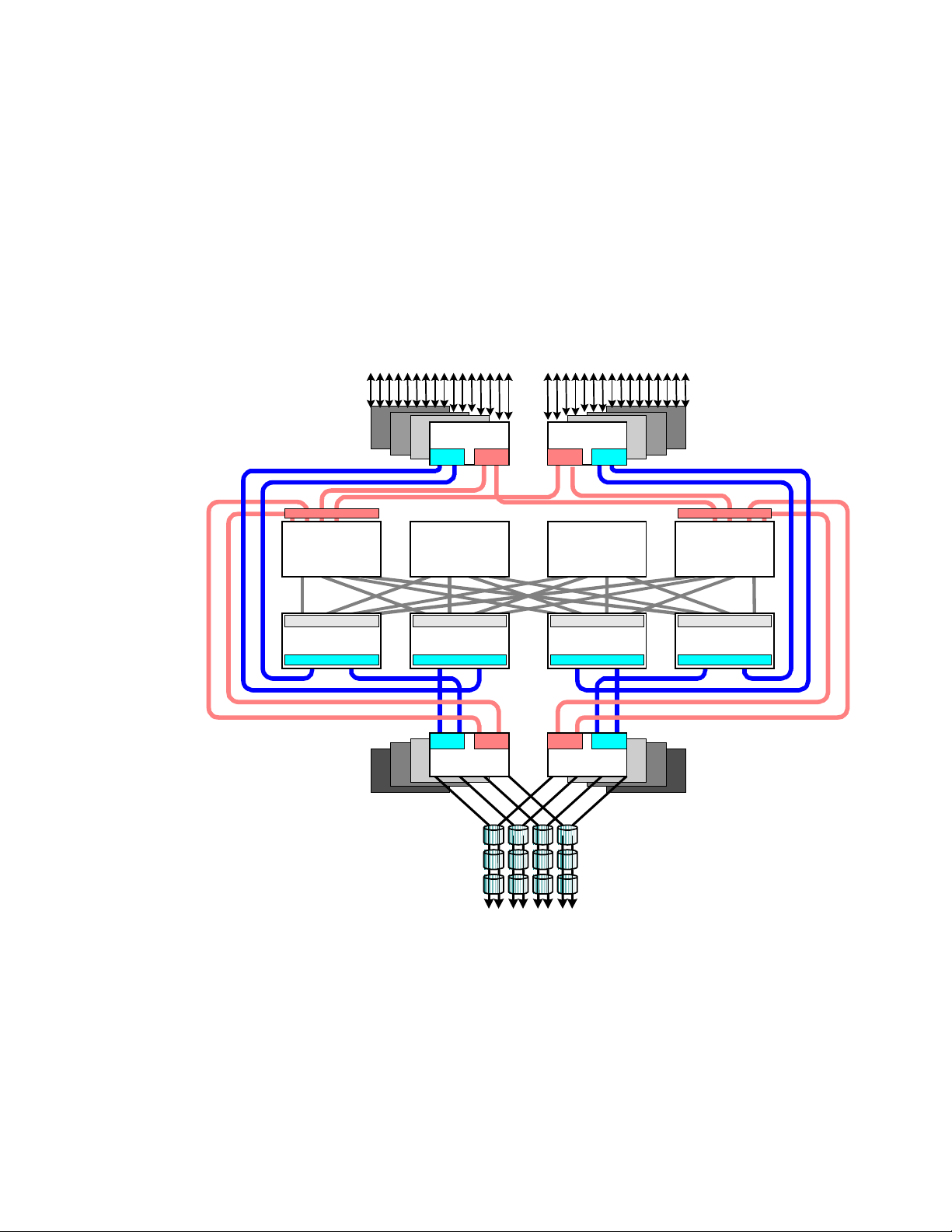
Figure 2.1 shows the Hierarchical Star Network (HiStar or HSN) architecture of the Lightning
9900™ RAID subsystem. The “front end” of the 9900 subsystem includes the hardware and
software that transfers the host data to and from cache memory, and the “back end”
includes the hardware and software that transfers data between cache memory and the disk
drives.
control cache
Data Cache
Cache/Data Side
Cache Switch
Processor Side
CHT
DTA MPA
CHT
DTAMPA
Data Cache Data Cache
Cache/Data Side
Cache Switch
Processor Side
DTA MPA
ACP
Cache/Data Side
Cache Switch
Processor Side
DTAMPA
ACP
control cache
Data Cache
Cache/Data Si de
Cache Switch
Processor Side
Figure 2.1 Lightning 9900™ HiStar Network (HSN) Architecture
Hitachi Lightning 9900™ User and Reference Guide 11
Page 26

Front End: The 9900 front end is entirely resident in the 9900 controller frame and includes
the client-host interface processors (CHIPs) that reside on the channel adapter (CHA or CHT)
boards. The CHIPs control the transfer of data to and from the host processors via the fibrechannel, ExSA™, and/or FICON™ channel interfaces and to and from cache memory via
independent high-speed paths through the cache switches (CSWs).
Each channel adapter board (CHA or CHT) can contain two or four CHIPs. The 9960
subsystem supports up to eight CHAs for a maximum of 32 host interfaces, and the 9910
subsystem supports up to six CHAs to provide a maximum of 24 host interfaces.
The 9960 controller contains four cache switch (CSW) cards, and the 9910 controller
contains two CSW cards.
Cache memory in the 9960 resides on two or four cards depending on features, and each
cache card is backed up by a separate battery. The 9910 supports two cache cards.
Shared memory resides on the first two cache cards and is provided with its own power
sources and backup batteries. Shared memory also has independent address and data
paths from the channel adapter and disk adapter boards.
Back End: The 9900 back end is controlled by the array control processors (ACPs) that reside
on the disk adapter boards in the 9900 controller frame. The ACPs control the transfer of
data to and from the disk arrays via high-speed fibre (100 MB/sec or 1 Gbps) and then to and
from cache memory via independent high-speed paths through the CSWs.
The disk adapter board (DKA) contains four ACPs. The 9960 subsystem supports up to
eight DKAs for a maximum of 32 ACPs. The 9910 subsystem supports two DKAs for a
maximum of eight ACPs.
The 9960 subsystem (see Figure 2.2) includes the following major components:
One controller frame containing the control and operational components of the
subsystem.
Up to six disk array frames containing the storage components (disk drive arrays) of the
subsystem.
The service processor (SVP) (see section 2.5). The 9900 SVP is located in the controller
frame and can only be used by authorized Hitachi Data Systems personnel.
The Remote Console PC (see section 2.6). The 9900 Remote Console PC can be attached
to multiple 9960 and/or 9910 subsystems via the 9900-internal local-area network (LAN).
The 9910 subsystem (see Figure 2.3) includes the following major components:
One frame containing the controller and disk components of the subsystem.
The service processor (SVP) (see section 2.5). The 9900 SVP is located in the controller
frame and can only be used by authorized Hitachi Data Systems personnel.
The Remote Console PC (see section 2.6). The 9900 Remote Console PC can be attached
to multiple 9960 and/or 9910 subsystems.
12 Chapter 2 Subsystem Architecture and Components
Page 27
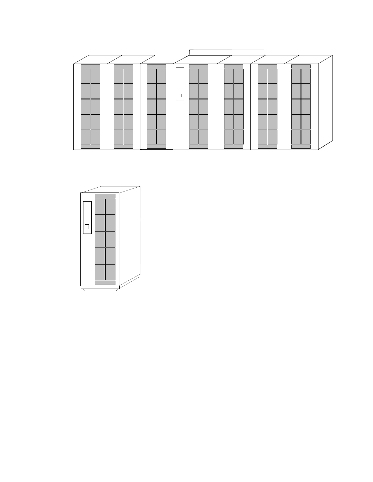
Minimum configuration of 9960 subsystem
Disk Array Unit Disk Array Unit Disk Array Unit 9900 Controller Disk Array Unit Disk Array Unit Disk Arr ay Unit
Figure 2.2 9960 Subsystem Frames
Figure 2.3 9910 Subsystem Frame
Hitachi Lightning 9900™ User and Reference Guide 13
Page 28

2.2 Components of the Controller Frame
The 9900 controller frame contains the control and operational components of the
subsystem. For the 9910 subsystem, the controller frame also contains the disk array
components. The 9900 controller is fully redundant and has no active single point of failure.
All controller frame components can be repaired or replaced without interrupting access to
user data. The key features and components of the controller frame are:
Storage clusters (see section 2.2.1),
Nonvolatile duplex shared memory (see section 2.2.2),
Nonvolatile duplex cache memory (see section 2.2.3),
Multiple data and control paths (see section 2.2.4),
Redundant power supplies (see section 2.2.5),
CHIPs and channels (FICON™, ExSA™, and/or fibre-channel) (see section 2.2.6),
ACPs (see section 2.2.8).
2.2.1 Storage Clusters
Each controller frame consists of two redundant controller halves called storage clusters.
Each storage cluster contains all physical and logical elements (e.g., power supplies, CHAs,
CHIPs, ACPs, cache, control storage) needed to sustain processing within the subsystem.
Both storage clusters should be connected to each host using an alternate path scheme, so
that if one storage cluster fails, the other storage cluster can continue processing for the
entire subsystem.
Each pair of channel adapters is split between clusters to provide full backup for both frontend and back-end microprocessors. Each storage cluster also contains a separate, duplicate
copy of cache and shared memory contents. In addition to the high-level redundancy that
this type of storage clustering provides, many of the individual components within each
storage cluster contain redundant circuits, paths, and/or processors to allow the storage
cluster to remain operational even with multiple component failures. Each storage cluster is
powered by its own set of power supplies, which can provide power for the entire subsystem
in the unlikely event of power supply failure. Because of this redundancy, the Lightning
9900™ subsystem can sustain the loss of multiple power supplies and still continue operation.
Note: The redundancy and backup features of the Lightning 9900™ subsystem eliminate all
active single points of failure, no matter how unlikely, to provide an additional level of
reliability and data availability.
14 Chapter 2 Subsystem Architecture and Components
Page 29

2.2.2 Nonvolatile Shared Memory
The nonvolatile shared memory contains the cache directory and configuration information
for the 9900 subsystem. The path group arrays (e.g., for dynamic path selection) also reside
in the shared memory. The shared memory is duplexed, and each side of the duplex resides
on the first two cache cards, which are in clusters 1 and 2. Even though the shared memory
resides on the cache cards, the shared memory has separate power supplies and separate
battery backup. The basic size of the shared memory is 512 MB, and the maximum size is 1.5
GB (for 9960). The size of the shared memory storage is determined by the total cache size
and the number of logical devices (LDEVs). Any required increase beyond the base size is
automatically shipped and configured during the upgrade process. The shared memory is
protected by battery backup.
2.2.3 Nonvolatile Duplex Cache
The 9960 subsystem can be configured with up to 32 GB of cache, and the 9910 can be
configured with up to 16 GB of cache. All cache memory in the 9900 is nonvolatile, and each
cache card is protected by its own 48-hour battery backup. The cache in the 9900 is divided
into two equal areas (called cache A and cache B) on separate cards. Cache A is in cluster 1,
and cache B is in cluster 2. The 9900 places all read and write data in cache. Write data is
normally written to both cache A and B with one CHIP write operation, so that the data is
always duplicated (duplexed) across logic and power boundaries. If one copy of write data is
defective or lost, the other copy is immediately destaged to disk. This “duplex cache”
design ensures full data integrity in the unlikely event of a cache memory or power-related
failure.
Note: Mainframe hosts can specify special attributes (e.g., cache fast write (CFW)
command) to write data (typically a sort command) without write duplexing. This data is not
duplexed and is usually given a discard command at the end of the sort, so that the data will
not be destaged to the disk drives. See section 4.3.3 for further information on S/390
operations.
®
cache
Hitachi Lightning 9900™ User and Reference Guide 15
Page 30

2.2.4 Multiple Data and Control Paths
The 9900 subsystem uses a state-of-the-art architecture called the Hierarchical Star (HiStar)
Network (HSN) which utilizes multiple point-to-point data and command paths in order to
provide redundancy and improve performance. Each data and command path is independent.
The individual paths between the channel or disk adapters and cache are steered by highspeed cache switch cards. The 9900 does not have any common buses, thus eliminating the
performance degradation and contention that can occur in a bus architecture. All data
stored on the 9900 subsystem is moved into and out of cache via the redundant high-speed
paths.
2.2.5 Redundant Power Supplies
Each storage cluster is powered by its own set of redundant power supplies, and each power
supply is able to provide power for the entire subsystem, if necessary. Because of this
redundancy, the 9900 subsystem can sustain the loss of multiple power supplies and still
continue operation. To make use of this capability, the 9900 should be connected either to
dual power sources or to different power panels, so if there is a failure on one of the power
sources, the 9900 can continue full operations using power from the alternate source.
2.2.6 Client-Host Interface Processors (CHIPs) and Channels
The CHIPs contain the front-end microprocessors which process the channel commands from
the host(s) and manage host access to cache. In the S/390
CKD-to-FBA and FBA-to-CKD conversion for the data in cache. The CHIPs are available in
pairs. Depending on the configuration, each CHIP in a pair contains either two or four
microprocessors and four buffers which allow data to be transferred between the CHIP and
cache. Each CHIP pair is composed of the same type of channel interface (FICON™, ExSA™, or
fibre-channel). Each ExSA™ or fibre-channel CHIP pair supports either four or eight
simultaneous data transfers to and from cache and four or eight physical connections to the
host. Each FICON™ CHIP pair supports four physical connections to the host. The 9900 can be
configured with multiple CHIP pairs to support various interface configurations. Table 2.1
lists the CHIP specifications and configurations and the number of channel connections for
each configuration.
Note: The Hitachi CruiseControl and Graph-Track products (see section 3.7) allow users to
collect and view usage statistics for the CHIPs in the 9900 subsystem.
®
environment, the CHIPs perform
16 Chapter 2 Subsystem Architecture and Components
Page 31
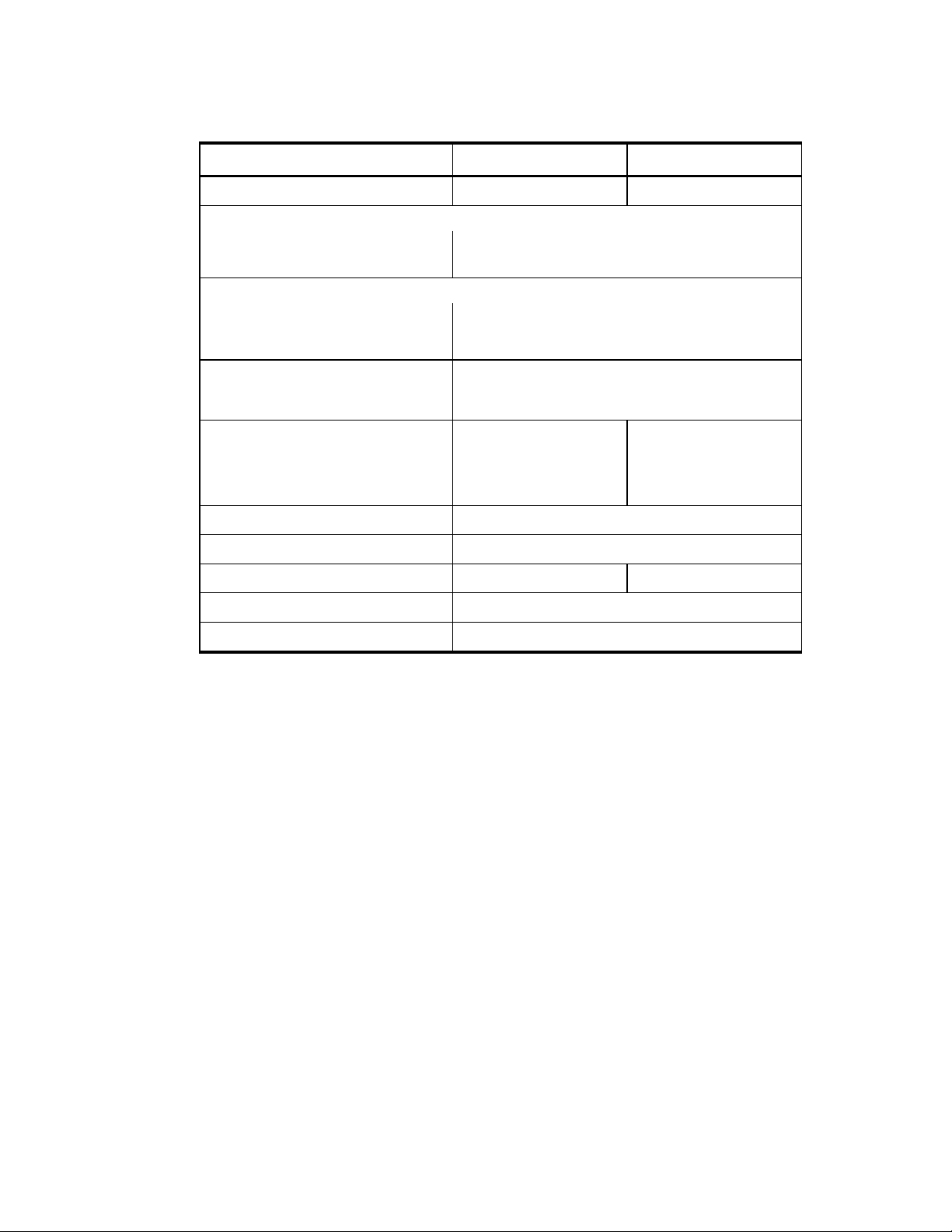
Table 2.1 CHIP and Channel Specifications
Parameter Specification for 9960 Specification for 9910
Number of CHIP pairs 1, 2, 3, or 4 1, 2, or 3
Simultaneous data transfers per CHIP pair:
S/390® 4 or 8 ExSA™ (serial/ESCON®)
Open Systems 4 or 8 (fibre-channel)
Maximum transfer rate:
FICON™ 100 MB/sec (1 Gbps)
ExSA™ (serial/ ESCON®) 10 or 17 MB/sec
Fibre 100 or 200 MB/sec (1 or 2 Gbps)
Physical interfaces per CHIP pair 4 or 8 ExSA™
4 FICON™
4 or 8 fibre-channel
Maximum physical interfaces per subsystem: 32 24
FICON™ 0, 4, 8, 12, or 16 0, 4, 8, or 12
ExSA™ (serial/ESCON®) 0, 4, 8, 12, 16, 20, 24, 28 or 32 0, 4, 8, 12, 16, 20, or 24
Fibre-channel 0, 4, 8, 12, 16, 20, 24, 28 or 32 0, 4, 8, 12, 16, 20, or 24
Logical paths per FICON™ port 512
Logical paths per ExSA™ (ESCON®) port 256
Maximum logical paths per subsystem 8,192 6144
Maximum LUs per fibre-channel port 256
Maximum LVI/LUs per subsystem 4,096
Hitachi Lightning 9900™ User and Reference Guide 17
Page 32

2.2.7 Channels
The Lightning 9900™ subsystem supports all-mainframe, multiplatform, and all-open system
operations and offers the following two types of host channel connections:
Fiber Connection (FICON™). The 9960 subsystem supports up to 16 FICON™-channel
ports, and the 9910 supports up to 12 FICON™ ports. The FICON™ ports are capable of
data transfer speeds of 100 MB/sec (1 Gbps). The 9900 FICON™-channel cards are
available with four ports per CHIP pair. The 9900 supports shortwave and longwave nonOFC (non-open FICON™ control) optical interface and multimode optical cables as well as
high-availability (HA) FICON™-channel configurations using hubs and switches. When
configured with shortwave FICON™ cards, the 9900 subsystem can be located up to 500
meters (2750 feet) from the host(s). When configured with longwave FICON™ cards, the
9900 subsystem can be located up to ten kilometers from the host(s).
Extended Serial Adapter™ (ExSA™). The 9960 subsystem supports a maximum of 32
ExSA™ serial channel interfaces (compatible with ESCON
®
protocol), and the 9910
supports a maximum of 24 ExSA™ interfaces. The 9900 ExSA™ channel interface cards
provide data transfer speeds of up to 17 MB/sec and are available in four or eight ports
per CHIP pair. Each ExSA™ channel can be connected to a single processor or logical
partition (LPAR) or to serial channel directors. Shared serial channels can be used for
dynamic path switching. The 9900 subsystem also supports the ExSA™ Extended Distance
Feature (XDF).
Fibre-Channel. The 9960 subsystem supports up to 32 fibre-channel ports, and the 9910
supports up to 24 fibre ports. The fibre ports are capable of data transfer speeds of 100
or 200 MB/sec (1 or 2 Gbps). The 9900 fibre-channel cards are available in either four or
eight ports per CHIP pair. The 9900 supports shortwave and longwave non-OFC (non-open
fibre control) optical interface and multimode optical cables as well as high-availability
(HA) fibre-channel configurations using hubs and switches. When configured with
shortwave fibre cards, the 9900 subsystem can be located up to 500 meters (2750 feet)
from the open-system host(s). When configured with longwave fibre cards, the 9900
subsystem can be located up to ten kilometers from the open-system host(s).
18 Chapter 2 Subsystem Architecture and Components
Page 33

2.2.8 Array Control Processors (ACPs)
A
The ACPs, which control the transfer of data between the disk drives and cache, are
installed in pairs for redundancy and performance. Figure 2.4 illustrates a conceptual ACP
pair domain. The 9960 can be configured with up to four ACP pairs, and the 9910 has one
ACP pair. All functions, paths, and disk drives controlled by one ACP pair are called an
“array domain.” An array domain can contain a variety of LVI and/or LU configurations.
The disk drives are connected to the ACP pairs by fibre cables using an arbitrated-loop
(FC-AL) topology. Each ACP has four microprocessors and four independent fibre backend
paths. Each 9960 fibre backend path can access up to 32 disk drives (32 drives × 4 paths =
128 disk drives per ACP). Each 9910 fibre backend path can access up to 12 disk drives (12
drives × 4 paths = 48 disk drives per ACP). Each disk drive is dual-ported for performance and
redundancy in case of a backend path failure.
Table 2.2 lists the ACP specifications. Each 9960 ACP pair can support a maximum of 128
physical disk drives (in three array frames), including dynamic spare disk drives. Each ACP
pair contains eight buffers (one per fibre path), that support data transfer to and from
cache. Each disk drive has a dual-port feature and can transfer data via either port. Each of
the two paths shared by the disk drive is connected to a separate ACP in the pair to provide
alternate path capability. Each ACP pair is capable of eight simultaneous data transfers to or
from the disk drives.
Note: The Hitachi CruiseControl and Graph-Track products (see section 3.7) allow users to
collect and view usage statistics for the ACPs in the 9900 subsystem.
ACP
Pair 4
MMaaxxiimmuumm FFoouurr AACCPP PPaaiirrs
ALL llooooppss == 33..22GGBB//ss
-
3322 FFCC-
ACP
Pair 3
ACP
Pair 1
s
ACP
Pair 2
Figure 2.4 Conceptual ACP Array Domain
Hitachi Lightning 9900™ User and Reference Guide 19
Page 34

Table 2.2 ACP Specifications
Description Specification for 9960 Specification for 9910
Number of ACP pairs 1, 2, 3 or 4 1
Backend paths per ACP pair 8
Backend paths per subsystem 8, 16, 24 or 32 8
Array group (or parity group) type per ACP pair RAID-1 and/or RAID-5
Hard disk drive type per ACP pair
Logical device emulation type within ACP pair 3380-x, 3390-x, and OPEN-x
[1]
18 GB, 47 GB, 73 GB, 146 GB, 180 GB
[3]
Backend array interface type Fibre-channel arbitrated loop (FC-AL)
Backend interface transfer rate (burst rate) 100 MB/sec (1 Gbps)
Maximum concurrent backend operations per ACP pair 8
Maximum concurrent backend operations per subsystem 32 8
HiStar Network architecture internal bandwidth 1.6 or 3.2 GB/sec 1.6 GB/sec
Notes:
1. All hard disk drives (HDDs) in an array group (also called parity group) must be the same type. Please contact your Hitachi
Data Systems representative for the latest information on available HDD types.
2. The 180-GB HDDs should not be intermixed with other HDD types in the same array domain (behind the same ACP pair).
See the notes under Table 2.3 for important information on 9900 subsystems which contain 180-GB HDDs.
3. 3390-3 and 3390-3R LVIs cannot be intermixed in the same 9900 subsystem.
[2]
20 Chapter 2 Subsystem Architecture and Components
Page 35

2.3 Array Frame
The 9960 array frames contain the physical disk drives, including the disk array groups and
the dynamic spare disk drives. Each array frame has dual AC power plugs, which should be
attached to two different power sources or power panels. The 9960 can be configured with
up to six array frames to provide a storage capacity of up to 88 TB. The 9910 subsystem
combines the controller and disk array components in one physical frame.
The 9900 subsystem uses three-inch disk drives with fixed-block-architecture (FBA) format.
The currently available disk drives have capacities of 18 GB, 47 GB, 73 GB, 146 GB, and 180
GB. All drives in an array group must have the same capacity. The 18-GB, 47-GB, 73-GB, and
146-GB HDDs can be attached to the same ACP pair. The 180-GB HDDs should not be
intermixed with other HDD types behind the same ACP pair. Table 2.3 provides the disk drive
specifications.
Each disk drive can be replaced nondisruptively on site. The 9900 utilizes diagnostic
techniques and background dynamic scrubbing that detect and correct disk errors. Dynamic
sparing is invoked automatically if needed. For both RAID-5 and RAID-1 array groups, any
spare disk drive can back up any other disk drive of the same capacity anywhere in the
subsystem, even if the failed disk and the spare disk are in different array domains
(attached to different ACP pairs). The 9960 can be configured with a minimum of one and a
maximum of sixteen spare disk drives. The 9910 can be configured with a minimum of one
and a maximum of four spare disk drives. The standard configuration provides one spare
drive for type of drive installed in the subsystem. The Hi-Track
tool detects disk drive failures and notifies the Hitachi Data Systems Support Center
automatically, and a service representative is sent to replace the disk drive.
®
monitoring and reporting
Note: The spare disk drives are used only as replacements and are not included in the
storage capacity ratings of the subsystem.
Hitachi Lightning 9900™ User and Reference Guide 21
Page 36

Table 2.3 Disk Drive Specifications
Disk Drive Type
Parameter
Formatted capacity (GB) 72.91 47.19 18.46 143.7 172.55
Platter diameter 3 inches 3 inches 3 inches 3 inches 3 inches
Physical cylinders (user area) 15,154 12,027 12,027 n/a 24,247
73 GB 47 GB 18 GB 146 GB 180 GB*
Physical tracks per physical cylinder
(number of heads)
Physical disk platters (user area)
(numbers of disks)
Sector length (byte) 520(512) 520(512) 520(512) 520 (512) 520(512)
Seek time (ms) MIN. 0.5/0.7 0.5/0.7 0.5/0.7 0.5/0.7 0.8 / 1.1
(Read/Write)
AVE. 5.7/6.5 5.7/6.5 5.2/6.0 4.9/5.4 7.4 / 8.2
Revolution speed (rpm) 10,025 10,025 10,025 10,025 7,200
Average latency time (ms) 2.99 2.99 2.99 2.99 4.17
Internal data transfer rate (MB/sec) 33.6 to 56.6 30.2 to 45.6 30.2 to 45.6 57.3 to 99.9 35.3 to 63.5
Max. interface data transfer rate
(MB/sec)
MAX. 12.0/13.0 12.0/13.0 12.0/13.0 10.0/11.0 16.0 / 17.0
24 (DKR1C)
10 (DKR2D)
12 (DKR1C)
5 (DKR2D)
100 100 100 100 100
23 (DKR1B)
16 (DKR1C)
12 (DKR1B)
8 (DKR1C)
9 (DKR2B)
6 (DKR2C)
5 (DKR2B)
3 (DKR2C)
10 24
5 12
*Caution and notes for the 180-GB HDDs:
Caution: The 180-GB HDDs should not be intermixed with other HDD types in the same
array domain (behind the same ACP pair). If 180-GB HDDs are used, all HDDs in that
array domain should also be 180-GB HDDs.
Note: Subsystems which contain the 180-GB HDDs do not have the same availability or
serviceability as those subsystems which do not contain 180-GB HDDs. Some offline
maintenance may be required.
Note: The 180-GB HDDs are intended for archival use and do not have characteristics
that make them suitable as performance devices.
22 Chapter 2 Subsystem Architecture and Components
Page 37

2.3.1 Disk Array Groups
The disk array group is the basic unit of storage capacity for the 9900. Each array group is
attached to both ACPs of an ACP pair via eight fibre paths, which enables all disk drives in
the array group to be accessed simultaneously by the ACP pair. All disk drives in an array
group must have the same logical capacity. Each array frame has two canister mounts, and
each canister mount can have up to 48 physical disk drives.
The 9900 supports both RAID-1 and RAID-5 array groups. Figure 2.5 illustrates a sample RAID1 layout. A RAID-1 array group consists of two pair of disk drives in a mirrored configuration,
regardless of disk drive capacity. Data is striped to two drives and mirrored to the other two
drives. The stripe consists of two data chunks. The primary and secondary stripes are
toggled back and forth across the physical disk drives for high performance. Each data chunk
consists of either eight logical tracks (S/390
in a drive causes the corresponding mirrored drive to take over for the failed drive. Although
the RAID-5 implementation is appropriate for many applications, the RAID-1 option on the
all-open 9900 subsystem is ideal for workloads with low cache-hit ratios.
RAID-1 using 2D + 2D and S/390® LDEVs
®
) or 768 logical blocks (open systems). A failure
Track 0
to
Track 7
Track 16
to
Track 23
Track 32
to
Track 39
Track 48
to
Track 55
Track 0
to
Track 7
Track 16
to
Track 23
Track 32
to
Track 39
Track 48
to
Track 55
Track 8
to
Track 15
Track 24
to
Track 31
Track 40
to
Track 47
Track 56
to
Track 63
Track 8
to
Track 15
Track 24
to
Track 31
Track 40
to
Track 47
Track 56
to
Track 63
Figure 2.5 Sample RAID-1 Layout
A RAID-5 array group consists of four disk drives. The data is written across the four hard
drives in a stripe that has three data chunks and one parity chunk. Each chunk contains
®
either eight logical tracks (S/390
) or 768 logical blocks (open systems). The enhanced RAID5+ implementation in the 9900 subsystem minimizes the write penalty incurred by standard
RAID-5 implementations by keeping write data in cache until an entire stripe can be built
and then writing the entire data stripe to the disk drives.
Hitachi Lightning 9900™ User and Reference Guide 23
Page 38

Figure 2.6 illustrates RAID-5 data stripes mapped over four physical drives. Data and parity
are striped across each of the disk drives in the array group (hence the term “parity group”).
The logical devices (LDEVs) are evenly dispersed in the array group, so that the performance
of each LDEV within the array group is the same. Figure 2.6 also shows the parity chunks
that are the “Exclusive OR” (EOR) of the data chunks. The parity and data chunks rotate
after each stripe. The total data in each stripe is either 24 logical tracks (eight tracks per
chunk) for S/390
®
data, or 2304 blocks (768 blocks per chunk) for open-systems data. Each of
these array groups can be configured as either 3380-x, 3390-x, or OPEN-x logical devices. All
LDEVs in the array group must be the same format (3380-x, 3390-x, or OPEN-x). For open
systems, each LDEV is mapped to a SCSI address, so that it has a TID and logical unit number
(LUN).
RAID-5 using 3D + P and S/390® LDEVs
Track 0
to
Track 7
Track 32
to
Track 39
next
8
tracks
Parity
Tracks
Track 15
Track 40
Track 47
Figure 2.6 Sample RAID-5 Layout (Data Plus Parity Stripe)
Note: The Hitachi CruiseControl and Graph-Track products (see section 3.7) allow users to
collect and view detailed usage statistics for the disk array groups in the 9900 subsystem.
2.3.2 Sequential Data Striping
Track 8
to
to
Parity
Tracks
next
8
tracks
Track 16
to
Track 23
Parity
Tracks
next
8
tracks
next
8
tracks
Parity
Tracks
Track 24
to
Track 31
next
8
tracks
next
8
tracks
The 9900 subsystem’s enhanced RAID-5+ implementation attempts to keep write data in
cache until parity can be generated without referencing old parity or data. This capability to
write entire data stripes, which is usually achieved only in sequential processing
environments, minimizes the write penalty incurred by standard RAID-5 implementations.
The device data and parity tracks are mapped to specific physical disk drive locations within
each array group. Therefore, each track of an LDEV occupies the same relative physical
location within each array group in the subsystem.
24 Chapter 2 Subsystem Architecture and Components
Page 39
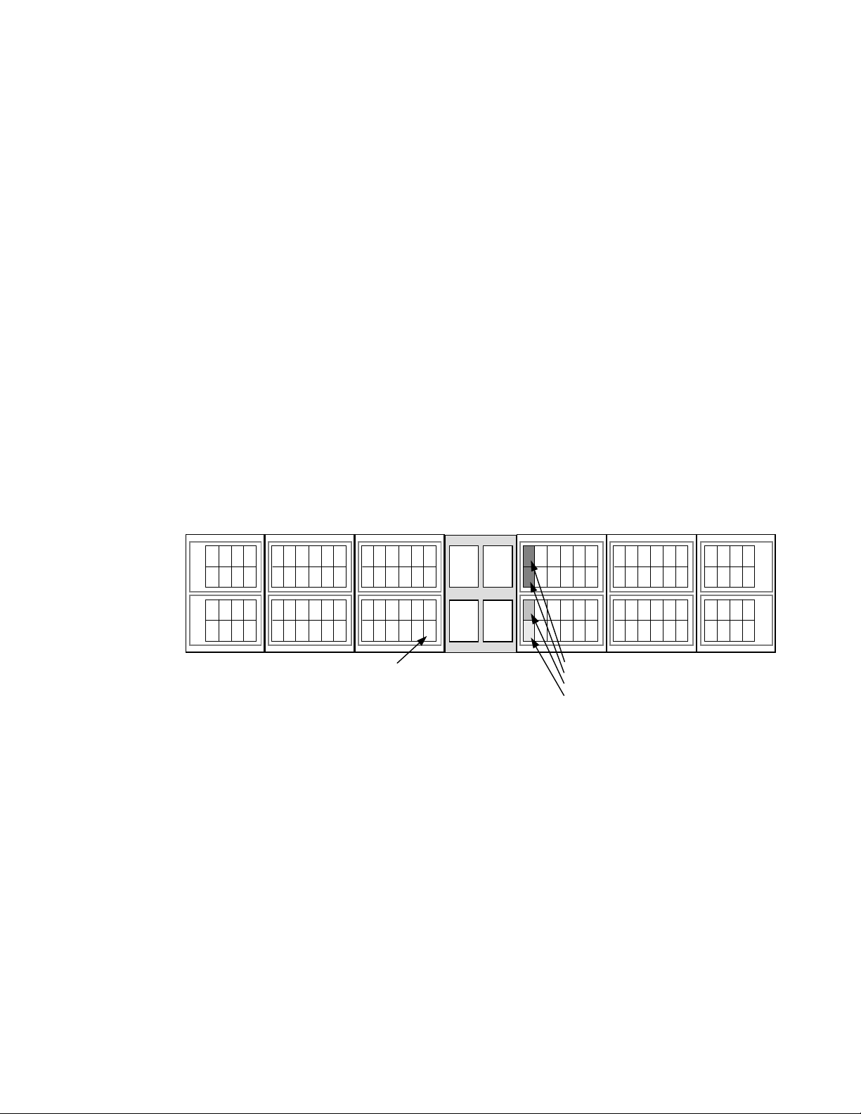
2.4 Intermix Configurations
y
y
y
y
y
2.4.1 RAID-1 & RAID-5 Intermix
RAID technology provides full fault-tolerance capability for the disk drives of the 9900
subsystem. The 9900 supports RAID-1, RAID-5, and intermixed RAID-1 and RAID-5
configurations, including intermixed array groups within an array domain. The cache
management algorithms (see section 3.3.1) enable the 9900 to stage up to one full RAID
stripe of data into cache ahead of the current access to allow subsequent access to be
satisfied from cache at host channel transfer speeds.
2.4.2 Hard Disk Drive Intermix
Figure 2.7 illustrates an intermix of hard disk drive types. All hard disk drives in one array
group must be of the same capacity and type. The 18-GB, 47-GB, 73-GB, and 146-GB HDDs
can be attached to the same ACP pair. The 180-GB HDDs should not be intermixed with other
HDD types behind the same ACP pair. See the notes under Table 2.3 for important
information on 9900 subsystems which contain 180-GB HDDs.
Disk Arra
Unit
Disk Arra
Unit
Disk Array
Unit
RAID group
RAID5: 3D+1P
RAID1: 2D+2D
Figure 2.7 Sample Hard Disk Drive Intermix
9900
Controller
4th
ACP
Pair
3rd
ACP
Pair
2nd
ACP
Pair
1st
ACP
Pair
Disk Arra
Unit
RAID group of 180-GB HDD
RAID group of 180-GB HDD
RAID group of 47-GB HDD
RAID group of 18-GB HDD
Disk Arra
Unit
Disk Arra
Unit
Hitachi Lightning 9900™ User and Reference Guide 25
Page 40

2.4.3 Device Emulation Intermix
y
y
y
y
y
y
The 9900 subsystem supports an intermix of different device emulations (e.g., 3390-x LVIs,
3380-x LVIs, OPEN-x LUs) on the same ACP pair. Figure 2.8 illustrates an intermix of device
emulation types. The only requirement is that the devices within each array group must
have the same type of track geometry or format, as follows:
3390-1, -2, -3 or -9 can be intermixed within an array group.
3380-E, -J, or -K can be intermixed within an array group.
OPEN-3, -8, -9, -E, -L, and -M can be intermixed within an array group with the following
restrictions:
– OPEN-L devices can only be configured on array groups of 73, 146, or 180 GB HDDs.
– OPEN-M devices can only be configured on array groups of 47 or 180 GB HDDs.
OPEN-K cannot be intermixed with other device types within an array group.
Note: For the latest information on supported LU types and intermix requirements, please
contact your Hitachi Data Systems account team.
Note: The 9960 and 9910 subsystems may support different device emulations and intermix
configurations.
Disk Arra
Unit
Disk Arra
Unit
Disk Arra
Unit
3390-9
3390-3
3380-K
Figure 2.8 Sample Device Emulation Intermix
9900
Controller
4th
ACP
Pair
3rd
ACP
Pair
2nd
ACP
Pair
1st
ACP
Pair
Disk Arra
Unit
OPEN-3
3390-9
OPEN-9
Disk Arra
Unit
Disk Arra
Unit
26 Chapter 2 Subsystem Architecture and Components
Page 41

2.5 Service Processor (SVP)
The Lightning 9900™ subsystem includes a built-in laptop PC called the service processor
(SVP). The SVP is integrated into the controller frame and can only be used by authorized
Hitachi Data Systems personnel. The SVP enables the Hitachi Data Systems representative to
configure, maintain, and upgrade the 9900 subsystem. The SVP also collects performance
data for all key components of the 9900 subsystem to enable diagnostic testing and analysis.
The Hitachi Graph-Track™ software product (see section 3.7.27) stores the SVP performance
data on the Remote Console PC and allows users to view the data in graphical format and
export the data for statistical analysis. Note: The SVP does not have access to any user data
stored on the 9900 subsystem.
2.6 Remote Console PC
The Remote Console PC is LAN-attached to one or more 9900 subsystems via the 9900internal LAN. The 9900 Remote Console PC supports the Windows
Windows
®
2000, and Windows NT® operating systems to provide a user-friendly interface for
®
95, Windows® 98,
the 9900 remote console software products. The remote console software communicates
directly with the SVP of each attached subsystem, enabling the user to view subsystem
configuration information and issue commands directly to the 9900 subsystems. For further
information on the Remote Console PC, please refer to the Hitachi Lightning 9900™ Remote
Console User’s Guide (MK-90RD003).
Hitachi Lightning 9900™ User and Reference Guide 27
Page 42

28 Chapter 2 Subsystem Architecture and Components
Page 43

Chapter 3 Functional and Operational Characteristics
3.1 New 9900 Features and Capabilities
The Hitachi Lightning 9900™ subsystem offers the following new or improved features and
capabilities which distinguish the 9900 subsystem from the 7700E subsystem:
Support for FICON™ channel interface.
Sixteen (16) logical control unit (CU) images.
State-of-the-art hard disk drives of 18-GB, 47-GB, 73-GB, 146-GB, and 180-GB capacities.
Up to 32 GB cache memory for the 9960 subsystem and 16 GB cache for the 9910.
Up to 32 host interface ports [ExSA™ (ESCON
Up to 16 host interface ports (FICON™).
Up to 256 logical paths per ExSA™ (ESCON
Up to 512 logical paths per FICON™ channel interface.
Up to 4096 device addresses.
®
) and/or fibre-channel].
®
) channel interface.
Prioritized port control for open-system users.
3.2 I/O Operations
The 9900 I/O operations are classified into three types based on cache usage:
Read hit: For a read I/O, when the requested data is already in cache, the operation is
classified as a read hit. The CHIP searches the cache directory, determines that the data
is in cache, and immediately transfers the data to the host at the channel transfer rate.
Read miss: For a read I/O, when the requested data is not currently in cache, the
operation is classified as a read miss. The CHIP searches the cache directory, determines
that the data is not in cache, disconnects from the host, creates space in cache, updates
the cache directory, and requests the data from the appropriate ACP pair. The ACP pair
stages the appropriate amount of data into cache, depending on the type of read I/O
(e.g., sequential).
Fast write: All write I/Os to the 9900 subsystem are fast writes, because all write data
is written to cache before being destaged to disk. The data is stored in two cache
locations on separate power boundaries in the nonvolatile duplex cache (see section
2.2.3). As soon as the write I/O has been written to cache, the 9900 subsystem notifies
the host that the I/O operation is complete, and then destages the data to disk.
Hitachi Lightning 9900™ User and Reference Guide 29
Page 44

3.3 Cache Management
3.3.1 Algorithms for Cache Control
The 9900 subsystem places all read and write data in cache, and 100% of cache memory is
available for read operations. The amount of fast-write data in cache is dynamically
managed by the cache control algorithms to provide the optimum amount of read and write
cache, depending on the workload read and write I/O characteristics.
The algorithms for internal cache control used by the 9900 include the following:
Hitachi Data Systems Intelligent Learning Algorithm. The Hitachi Data Systems
Intelligent Learning Algorithm identifies random and sequential data access patterns and
selects the amount of data to be “staged” (read from disk into cache). The amount of
data staged can be a record, partial track, full track, or even multiple tracks, depending
on the data access patterns.
Least-recently-used (LRU) algorithm (modified). When a read hit or write I/O occurs in
a nonsequential operation, the least-recently-used (LRU) algorithm marks the cache
segment as most recently used and promotes it to the top of the appropriate LRU list. In
a sequential write operation, the data is destaged by priority, so the cache segment
marked as least-recently used is immediately available for reallocation, since this data is
not normally accessed again soon.
Sequential prefetch algorithm. The sequential prefetch algorithm is used for
sequential-access commands or access patterns identified as sequential by the
Intelligent Learning Algorithm. The sequential prefetch algorithm directs the ACPs to
prefetch up to one full RAID stripe (24 tracks) to cache ahead of the current access. This
allows subsequent access to the sequential data to be satisfied from cache at host
channel transfer speeds.
Note: The 9900 subsystem supports S/390
specifying cache functions.
3.3.2 Write Pending Rate
The write pending rate is the percent of total cache used for write pending data. The
amount of fast-write data stored in cache is dynamically managed by the cache control
algorithms to provide the optimum amount of read and write cache based on workload I/O
characteristics. Hitachi CruiseControl and Graph-Track allow users to collect and view the
write-pending-rate data and other cache statistics for the Lightning 9900™ subsystem.
Note: If the write pending limit is reached, the 9900 sends DASD fast-write delay or retry
indications to the host until the appropriate amount of data can be destaged from cache to
the disks to make more cache slots available.
®
extended count key data (ECKD) commands for
30 Chapter 3 Functional and Operational Characteristics
Page 45

3.4 Control Unit (CU) Images, LVIs, and LUs
3.4.1 CU Images
The 9900 subsystem supports the following logical CU images (emulation types): 3990-3,
3990-6E, and 2105. The 9900 subsystem is configured with one logical CU image for each 256
devices (one storage subsystem ID (SSID) for each 64 or 256 devices) to provide a maximum
of sixteen CU images per subsystem. The S/390
subsystem may have restrictions on CU image compatibility. FICON™ support requires
2105-F20 emulation. For further information on CU image support, please contact your
Hitachi Data Systems account team.
3.4.2 Logical Volume Image (LVIs)
The 9900 subsystem supports the following S/390® LVI types: 3390-1, -2, -3, -3R, -9; 3380-E,
-J, -K. The LVI configuration of the subsystem depends on the RAID implementation and
physical disk drive capacities. See section 4.1 for further information on LVI configurations.
3.4.3 Logical Unit (LU) Type
The 9900 subsystem currently supports the following LU types: OPEN-3, OPEN-8, OPEN-K,
OPEN-9, OPEN-E, OPEN-L, and OPEN-M. Table 3.1 lists the capacities for each standard LU
type. The 9900 also allows users to configure custom-size LUs which are smaller than
standard LUs as well as size-expanded LUs which are larger than standard LUs. LU Size
Expansion (LUSE) volumes can range in size from 3.748 (OPEN-K*2) to 524.448 GB (OPENE*36). Each LU is identified by target ID (TID) and LU number (LUN) (see Figure 3.1). Each
9900 fibre-channel port supports addressing capabilities for up to 256 LUNs.
®
data management features of the 9900
Table 3.1 Capacities of Standard LU Types
LU Type OPEN-K OPEN-3 OPEN-8 OPEN-9 OPEN-E OPEN-L OPEN-M
Capacity (GB)
Host
One 9900
fibre port
1.881 2.461 7.347 7.384 14.568 36.450 47.185
Initiator ID
LUN 0 to 255
Other Fibre
device
Target ID Target ID
Each fibre TID must be
unique and within the range
from 0 to EF (hexadecimal).
Other Fibre
device
Figure 3.1 Fibre-Channel Device Addressing
Hitachi Lightning 9900™ User and Reference Guide 31
Page 46

3.5 System Option Modes
To provide greater flexibility and enable the 9900 to be tailored to unique customer
operating requirements, additional operational parameters, or system option modes, are
available for the 9900 subsystem. At installation, the 9900 modes are set to their default
values (OFF), so make sure to discuss these settings with your Hitachi Data Systems team.
The 9900 modes can only be changed by the Hitachi Data Systems representative.
Table 3.2 – Table 3.8 show the public 9900 system option modes. Note: This 9900 mode
information was current at the time of publication of this document but may change. Please
contact your Hitachi Data Systems representative for the latest information on the 9900
System Option Modes.
Table 3.2 Common System Option Modes
Mode Level Description and Usage
22 Mandatory Controlling option for correction/drive copy: Turn mode 22 ON (nondisruptive) after the completion of the
micro-program exchange to microcode 01-18-67-00/00 or higher. Do NOT activate this mode unless
running the minimum microcode level indicated.
Also improves destage schedule to support large-capacity HDD (146-GB and higher).
ON: Controlling option for correction/ drive copy is active.
OFF: Controlling option for correction/ drive copy is not active.
Table 3.3 System Option Modes for Mainframe Connectivity
Mode Level Description and Usage
1 Optional PDS search assist by learning algorithm.
ON: 9900 performs PDS search assist by learning algorithm.
OFF: 9900 performs PDS search assist by host indication.
Microcode level: 01-10-00-00/10 and higher.
3 Optional EPW function for ascending record number in a cylinder.
ON: EPW can work to ascending record number in a cylinder.
OFF: EPW cannot work to ascending record number in a cylinder.
Microcode level: 01-10-00-00/10 and higher.
5 Optional SIM reporting option regarding drive/media SIM for 3380-K.
ON: DKC sends drive/media SIM for 3380-K to host.
OFF: DKC does not send drive/media SIM for 3380-K to host.
Microcode level: 01-10-00-00/10 and higher.
6 Optional "Suppression of reporting SSB F/M=6X. For VSE/FASTCOPY Copy job"
ON: DKC does not report SSB F/M=6X to host.
OFF: DKC reports SSB F/M=6X to host.
Microcode level: From 01-10-00-00/10 to 01-13-01-00/00.
162 Optional Tuning option for mainframe performance.
Do not set MODE162=ON to the subsystem which has less than 01-18-48-00/00.
ON: Tuning for sequential write performance is inactive.
OFF: Tuning for sequential write performance is active.
32 Chapter 3 Functional and Operational Characteristics
Page 47

Table 3.4 System Option Modes for Open-System Connectivity
Mode Level Description and Usage
57 Optional SIM notification to open-system host.
ON: 9900 reports SIM to open-system host as Sense Key/Sense code.
OFF: 9900 does not send SIM to open-system host.
SIM will be reported as B/C300. EC=D002 will be logged in SSB.log.
Set host mode 04 and System option MODE 56,57 for Sequent.
Microcode level: 01-10-00-00/10 and higher.
111 Optional LUN security option.
ON: DKC checks all command for LUN security.
OFF: DKC does not check all command for LUN security.
161 Optional Suppression of high speed micro-program exchange for CHT.
ON: 9900 does not perform high speed micro-program for CHT. New micro-program is also written into
flash memory on the CHT.
OFF: 9900 does perform high speed micro-program for CHT. Only the microprocessor code is loaded.
Either a PS OFF/ON or a dummy replace of the CHT board will be required for the subsequent loadingof
flash memory.
Microcode level: 01-11-xx and higher.
185 Mandatory Solaris + SUN Cluster 3.0 or SDS4.2.1.
ON: Mandatory setting when SUN Cluster 3.0 or SDS4.2.1 is connected.
OFF: SUN Cluster 3.0 or SDS4.2.1 should never be connected with this setting.
Micro-code level: 01-15-39-00/0x and higher.
186 Mandatory VERITAS Database Editions/Advanced Cluster.
ON: Mandatory setting when VERITAS Database Editions/Advanced Cluster is connected.
OFF: VERITAS Database Editions/Advanced Cluster should never be connected with this setting.
Microcode level: 01-17-94-00/10 and higher.
198 Mandatory Tru64 5.1a connection.
ON: Mandatory setting when Tru64 5.1a is connected.
OFF: Tru64 5.1a should never be connected with this setting.
Microcode level: 01-16-60-00/00 and higher.
206 Mandatory An inhibit option regarding Q-Err expansion bit.
ON: DKC inhibits AIX Q-Err expansion bit.
OFF: DKC does not inhibit AIX Q-Err expansion bit.
Microcode level: 01-18-42-00/00 and higher.
213 Mandatory AIX + HACMP
ON: Mandatory setting when AIX + HACMP is connected.
OFF: AIX + HACMP should never be connected with this setting.
Microcode level: 01-17-94-00/06 and higher.
247 Mandatory Tru64 (Recognition of LUN). Micro-program has been modified to change Vendor ID and Product ID as
response of Inquiry command with system option MODE 247 for Tru64 connection as shown below.
Do not set MODE 247=ON if the subsystem is already connected to Tru64 with old microcode.
Set MODE 247=ON if the subsystem is to be newly connected toTru64 with 01-18-92-00/00 and later.
Note: The function of MODE 247 is suppressed when MODE 198 =ON.
ON: Mandatory setting when Tru64 is connected.
OFF: Tru64 should never be connected with this setting.
Microcode level: 01-19-92-00/00 and higher.
Hitachi Lightning 9900™ User and Reference Guide 33
Page 48

Table 3.5 System Option Modes for ShadowImage - S/390
Mode Level Description and Usage
80 Optional ShadowImage Quick Restore function.
ON: 9900 does not perform the ShadowImage Quick Restore function.
OFF: 9900 performs the ShadowImage Quick Restore function.
87 Optional Quick Resync by CCI (RAID Manager).
ON: 9900 performs ShadowImage quick resync operation for Resync command from CCI.
OFF: 9900 does not perform ShadowImage quick resync operation for Resync command from CCI.
Microcode level: 01-13-18-00/07 and higher.
122 Optional ShadowImage Quick Split and Quick Resync functions.
ON: 9900 does not perform ShadowImage quick split and quick resync operations.
OFF: 9900 performs ShadowImage quick split and quick resync operations.
®
and ShadowImage
Table 3.6 System Option Modes for TrueCopy - S/390® Synchronous & Asynchronous (continues on the
next page)
Mode Level Description and Usage
20 Optional Enables TC390 – R-VOL read-only function (RCU only).
ON: R-VOL read only function is available.
OFF: R-VOL read only function is not available.
Microcode level: 01-10-00-00/10 and higher.
36 Optional TC390 Synchronous – Selects function of CRIT=Y(ALL) or CRIT=Y(PATHS).
ON: CRIT=Y(ALL) => equivalent to Fence Level = Data.
OFF: CRIT=Y(PATHS) => equivalent to Fence Level = Status.
Microcode level: 01-10-00-00/10 and higher.
38 Optional TC390 – Changes SSB reported against the WRITE I/O to the M-VOL in critical state.
ON: Intervention required.
OFF: Command rejected (PPRC specification).
Microcode level: 01-10-00-00/10 and higher.
49 Optional TC390 – Changes reporting of SSIDs in response to CQUERY command (which is limited to four SSIDs).
When 64 LDEVs per SSID are defined, mode 49 must be ON for TC390, GDPS, and P/DAS operations.
When 256 LDEVs per SSID are defined, mode 49 must be OFF.
ON: Report first SSID for all (256) devices in the logical CU.
OFF: Report SSID specified for each 64 or 256 devices.
Microcode level: 01-10-00-00/10 and higher.
64 Optional TC390 CGROUP – Defines scope of CGROUP command within the 9900. Must be OFF for GDPS.
ON: All TC390 volumes in this 9900 subsystem.
OFF: TC390 volumes behind the specified LCU pair (main and remote LCUs).
Microcode level: 01-10-00-00/10 and higher.
34 Chapter 3 Functional and Operational Characteristics
Page 49

Table 3.6
Mode Level Description and Usage
93 Optional TC390 Asynchronous graduated delay process for sidefile control.
104 Optional TC390 CGROUP – Selects subsystem default for CGROUP FREEZE option. Applies only to 3990
114 Optional TC390 – Allows dynamic port mode setting (RCP/LCP for serial, Initiator/RCU target for fibre-channel)
System Option Modes for TrueCopy - S/390
ON: soft delay type.
OFF: strong delay type.
Amount of sidefile Strong delay type Soft delay type
----------------------------------------------------------------------------------------threshold – [15-20%] (HWM) 100 ms x 1 time 20 ms x 1 time
threshold – [10-15%] 200 ms x 1 time 40 ms x 1 time
threshold – [5-10%] 300 ms x 1 time 60 ms x 1 time
threshold – [0-5%] 400 ms x 1 time 80 ms x 1 time
threshold or higher 500 ms x permanent 100 ms x permanent
Microcode level: 01-13-18-00/07 and higher.
controller emulation. Note: Mode 104 is invalid if the controller emulation is 2105. For 2105, use the
CGROUP option of CESTPATH.
ON: FREEZE enabled.
OFF: FREEZE disabled.
Microcode level: 01-10-00-00/10 and higher.
through PPRC CESTPATH and CDELPATH commands.
ON: Set defined port to RCP/LCP mode (serial) or Initiator/RCU target mode (fibre-channel) as needed.
OFF: Port must be reconfigured using Remote Console PC (or SVP).
Microcode level: 01-10-00-00/10 and higher.
Note: For fibre-channel interface, do not use the CESTPATH and CDELPATH commands at the same
time as the SCSI path definition function of LUN Manager. The FC interface ports need to be configured
as initiator ports or RCU target ports before the CESTPATH and CDELPATH commands are issued.
Caution: Before issuing the CESTPATH command, you must make sure that the relevant paths are
offline from the host(s) (e.g., configure the Chipid offline, or deactivate the LPAR, or block the port in the
ESCD). If any active logical paths still exist, the add path operation will fail because the port mode
(LCP/RCP) cannot be changed.
®
Synchronous & Asynchronous (continued)
118 Optional HXRC, CC, TC390A – SIM notification when:
HXRC+CC sidefile reaches sleep wait threshold (see modes 45, 85, 86, 97).
TC390A sidefile reaches high-water mark (HWM = sidefile threshold - 20%) (see mode 93).
ON: Generate SIM.
OFF: Do not generate SIM.
Microcode level: 01-10-00-00/10 and higher.
Hitachi Lightning 9900™ User and Reference Guide 35
Page 50

Table 3.7 System Option Modes for HXRC
Mode Level Description and Usage
45 Optional Sleep Wait suppressing option (see modes 61, 85, 86, 97). When Mode 45 is ON and Mode 61 is ON,
61 Optional Enables the DONOTBLOCK option of the XADDPAIR command. Must be OFF if the operating system
85,86 Optional Variable sidefile threshold.
97 Optional Variable Sleep Wait timer duration (see modes 45, 85, 86).
98 Optional Selects SCP or session cancel (see modes 45, 85, 86).
WRITE I/Os for LDEVs are blocked by the threshold specified by SDM.
ON: Sidefile threshold does not activate Sleep Wait timer at the sleep wait threshold.
OFF: Sidefile threshold activates Sleep Wait timer at the sleep wait threshold.
Microcode level: -10-00-00/10 and higher.
does not support the DONOTBLOCK option.
ON: DONOTBLOCK option activated.
OFF: DONOTBLOCK option ignored.
Microcode level: 01-12-18-00/00 and higher.
Mode 85 ON and mode 86 OFF: Thresholds for Sleep wait/SCP/Puncture = 30/40/50%
Mode 85 OFF and mode 86 OFF: Thresholds for Sleep wait/SCP/Puncture = 40/50/60%
Mode 85 OFF and mode 86 ON: Thresholds for Sleep wait/SCP/Puncture = 50/60/70%
Mode 85 ON and mode 86 ON: Thresholds for Sleep wait/SCP/Puncture = 60/70/80%
Microcode level: 01-12-18-00/00 and higher.
ON: Sleep Wait timer duration = 10 ms.
OFF: Sleep Wait timer duration = 100 ms.
Microcode level: 01-10-00-00/10 and higher.
ON: Forced session cancel.
OFF: SCP.
Microcode level: 01-10-00-00/10 and higher.
118 Optional HXRC, CC, TC390A – SIM notification when:
HXRC+CC sidefile reaches sleep wait threshold (see modes 45, 85, 86, 97).
TC390A sidefile reaches high-water mark (HWM = sidefile threshold - 20%) (see mode 93).
ON: Generate SIM.
OFF: No SIM generated.
Microcode level: 01-10-00-00/10 and higher.
Table 3.8 System Option Modes for Concurrent Copy (CC)
Mode Level Description and Usage
118 Optional HXRC, CC, TC390A – SIM notification when:
HXRC+CC sidefile reaches sleep wait threshold (see modes 45, 85, 86, 97).
TC390A sidefile reaches high-water mark (HWM = sidefile threshold - 20%) (see mode 93).
ON: Generate SIM.
OFF: No SIM generated.
Microcode level: 01-10-00-00/10 and higher.
36 Chapter 3 Functional and Operational Characteristics
Page 51

3.6 Open Systems Features and Functions
The 9900 subsystem offers many features and functions specifically for the open-systems
environment. The 9900 supports multi-initiator I/O configurations in which multiple host
systems are attached to the same fibre-channel interface. The 9900 subsystem also supports
important open-system functions such as fibre-channel arbitrated-loop (FC-AL) and fabric
topologies, command tag queuing, multi-initiator I/O, and industry-standard middleware
products which provide application and host failover, I/O path failover, and logical volume
management functions. In addition, several program products and services are specifically
for open systems. See section 3.7 for more information.
3.6.1 Failover and SNMP Support
The 9900 subsystem supports industry-standard products and functions which provide host
and/or application failover, I/O path failover, and logical volume management (LVM),
including Hitachi Dynamic Link Manager™, VERITAS
VERITAS
Sequent Multi Path, Sequent Cluster Control, VMSCluster, Novell
Cluster Server. For the latest information on failover and LVM product releases, availability,
and compatibility, please contact your Hitachi Data Systems account team.
®
Volume Manager/DMP, Sun Cluster, TruCluster, HP® MC/ServiceGuard, HACMP,
®
FirstWatch®, VERITAS® Cluster Server,
®
Cluster Server, Microsoft®
The 9900 subsystem also supports the industry-standard simple network management
protocol (SNMP) for remote subsystem management from the UNIX
used to transport management information between the 9900 subsystem and the SNMP
manager on the host. The SNMP agent for the 9900 subsystem sends status information to
the host(s) when requested by the host or when a significant event occurs.
3.6.2 Share-Everything Architecture
The 9900 subsystem’s global cache provides a “share-everything” architecture that enables
any fibre-channel port to have access to any LU in the subsystem. In the 9900, each LU can
be assigned to multiple fibre-channel ports to provide I/O path failover and/or load
balancing (with the appropriate middleware support) without sacrificing cache coherency.
The LUN mapping can be performed by the user using the LUN Manager remote console
software, or by your Hitachi Data Systems representative (fee-based configuration service).
3.6.3 SCSI Extended Copy Command Support
The Extended Copy Manager (ECM) feature of the 9900 subsystem (see section 3.7.6)
supports the SCSI Extended Copy (e-copy) command issued from the host server to the 9900
subsystem. ECM provides a server-free backup solution between the 9900 subsystem and
backup devices (e.g., tape, disk) in a storage-area network (SAN) environment, eliminating
server CPU and I/O overhead during movement of data and decreasing the time required for
backup. The e-copy (backup) operations are performed via fibre-channel interfaces directly
to the backup devices. ECM operations are configured using the LUN Manager software on
the Remote Console PC. To implement ECM operations, you need a backup application on
the host server to issue the Extended Copy commands to the 9900 subsystem.
®
/PC server host. SNMP is
Hitachi Lightning 9900™ User and Reference Guide 37
Page 52

3.7 Data Management Functions
The 9900 subsystem provides features and functions that increase data availability and
improve data management. Table 3.9 and Table 3.10 list the data management features that
are currently available for the 9900 subsystem. Please refer to the appropriate user
documentation for more details.
Table 3.9 Data Management Functions for Open-System Users
Controlled by:
Feature Name
Replication:
TrueCopy (section 3.7.1) Yes Yes Yes MK-91RD051
Hitachi ShadowImage (section 3.7.3) Yes Yes Yes MK-90RD031
Command Control Interface (CCI) (section 3.7.5) No Yes Yes MK-90RD003
Extended Copy Manager (ECM) (section 3.7.6) Yes Yes Yes MK-91RD049
Data Migration (section 3.7.9) Yes No No Service Offering
Backup/restore and sharing:
Hitachi RapidXchange (HRX) (section 3.7.10) No Yes Yes MK-90RD020
Hitachi Multiplatform Backup/Restore (HMBR) (section 3.7.11) No Yes Yes MK-90RD037
HARBOR® File-Level Backup and Restore (section 3.7.12) No No No Service Offering
HARBOR® File Transfer (section 3.7.13) No Yes Yes Service Offering
Resource management:
HiCommand™ (section 3.7.14) Yes No Yes
LUN Manager (section 3.7.15), Yes No Yes MK-91RD049
LUSE (section 3.7.16) Yes No Yes MK-91RD049
Virtual LUN (section 3.7.17) Yes No Yes MK-90RD005
FlashAccess (section 3.7.18) Yes Yes Yes MK-90RD004
Hitachi SANtinel (section 3.7.20) Yes No Yes MK-91RD049
Prioritized Port Control (section 3.7.22) Yes No Yes MK-90RD030
Hitachi Dynamic Link Manager™ (section 3.7.24) No Yes Yes
LDEV Guard (section 3.7.25) Yes Yes Yes MK-92RD072
Remote
Console?
Host
Licensed
OS?
Software? User Document(s)
Web Client: MK-91HC001
Server: MK-91HC002
Security: MK-91HC003
HiScan: MK-91HC005
Command Line Interface: MK-91HC007
®
For AIX
systems: MK-91RD056
For Solaris™ systems: MK-91RD057
For Windows
For HP-UX® systems: MK-91RD059
®
systems: MK-91RD058
Storage utilities:
Hitachi CruiseControl (section 3.7.26) Yes No Yes MK-91RD054
Hitachi Graph-Track (section 3.7.27) Yes No Yes MK-90RD032
Network solutions:
Hitachi Freedom NAS™ (section 1.1.5) N/A N/A N/A MK-91RD053
Hitachi Freedom SAN™ (section 1.1.5) N/A N/A N/A N/A
38 Chapter 3 Functional and Operational Characteristics
Page 53

Table 3.10 Data Management Functions for S/390
Controlled by:
Feature Name
Replication:
TrueCopy – S/390® (section 3.7.2) Yes Yes Yes MK-91RD050
Hitachi ShadowImage – S/390® (section 3.7.4) Yes Yes Yes MK-90RD012
Hitachi Extended Remote Copy (HXRC) (section 3.7.7) No Yes No
Hitachi NanoCopy™ (section 3.7.8) N/A N/A N/A MK-90DD878, Service Offering
Data Migration (section 3.7.9) Yes No No Service Offering
Backup/restore and sharing:
Hitachi RapidXchange (HRX) (section 3.7.10) No Yes Yes MK-90RD020
Resource management:
Virtual LVI (section 3.7.17) Yes No Yes MK-90RD005
FlashAccess (section 3.7.18) Yes
Cache Manager (section 3.7.19)
Hitachi SANtinel – S/390® (section 3.7.21) Yes No Yes MK-90RD036
Hitachi Parallel Access Volume (HPAV) (section 3.7.23) Yes Yes Yes MK-91RD047
Storage utilities:
Hitachi CruiseControl (section 3.7.26) Yes No Yes MK-91RD054
Hitachi Graph-Track™ (section 3.7.27) Yes No Yes MK-90RD032
®
Users
Remote
Console?
Yes –
FlashAccess
Host
OS?
Yes –
Cache
Manager
Yes No MK-91RD045
Licensed
Software? User Document(s)
Planning for IBM Remote Copy, SG242595; Advanced Copy Services, SC350355; DFSMS MVS V1 Remote Copy
Guide and Reference, SC35-0169
Yes MK-90RD004
Hitachi Lightning 9900™ User and Reference Guide 39
Page 54

3.7.1 Hitachi TrueCopy (TC)
Hitachi TrueCopy enables open-system users to perform synchronous and/or asynchronous
remote copy operations between 9900 subsystems. The user can create, split, and
resynchronize LU pairs. TrueCopy also supports a “takeover” command for remote host
takeover (with the appropriate middleware support). Once established, TrueCopy operations
continue unattended and provide continuous, real-time data backup. Remote copy
operations are nondisruptive and allow the primary TrueCopy volumes to remain online to all
hosts for both read and write I/O operations. TrueCopy operations can also be performed
between 9900, 7700E, and 7700 subsystems (the 7700 supports only synchronous remote
copy).
Hitachi TrueCopy supports both serial (ESCON
between the main and remote 9900 subsystems. For serial interface connection, TrueCopy
operations can be performed across distances of up to 43 km (26.7 miles) using standard
®
ESCON
support. For fibre-channel connection, TrueCopy operations can be performed
across distances of up to 30 km (18.6 miles) using single-mode longwave optical fibre cables
in a switch configuration. Long-distance solutions are provided, based on user requirements
and workload characteristics, using approved channel extenders and communication lines.
Note: For further information on Hitachi TrueCopy, please see the Hitachi Lightning 9900™
Hitachi TrueCopy User and Reference Guide (MK-91RD051), or contact your Hitachi Data
Systems account team.
3.7.2 Hitachi TrueCopy – S/390® (TC390)
Hitachi TrueCopy – S/390® (TC390) enables S/390® users to perform synchronous and
asynchronous remote copy operations between 9900 subsystems. Hitachi TrueCopy – S/390
can be used to maintain copies of data for backup or duplication purposes. Once established,
TC390 operations continue unattended and provide continuous, real-time data backup.
Remote copy operations are nondisruptive and allow the primary TrueCopy volumes to
remain online to all hosts for both read and write I/O operations.
Hitachi TrueCopy – S/390
connections between the main and remote 9900 subsystems. Remote copy operations can
also be performed between 9900, 7700E, and 7700 subsystems (with some restrictions, e.g.,
the 7700 does not support asynchronous remote copy).
®
also supports both serial (ESCON®) and fibre-channel interface
®
) and fibre-channel interface connections
®
Note: For further information on Hitachi TrueCopy – S/390
Lightning 9900™ Hitachi TrueCopy – S/390
®
User and Reference Guide (MK-91RD050), or
contact your Hitachi Data Systems account team.
40 Chapter 3 Functional and Operational Characteristics
®
, please see the Hitachi
Page 55

3.7.3 Hitachi ShadowImage (SI)
Hitachi ShadowImage enables open-system users to maintain subsystem-internal copies of
LUs for purposes such as data backup or data duplication. The RAID-protected duplicate LUs
(up to nine) are created within the same 9900 subsystem as the primary LU at hardware
speeds. Once established, ShadowImage operations continue unattended to provide
asynchronous internal data backup. ShadowImage operations are nondisruptive; the primary
LU of each ShadowImage pair remains available to all hosts for both read and write
operations during normal operations. Usability is further enhanced through a
resynchronization capability that reduces data duplication requirements and backup time,
thereby increasing user productivity. ShadowImage also supports reverse resynchronization
for maximum flexibility.
ShadowImage operations can be performed in conjunction with Hitachi TrueCopy operations
(see section 3.7.1) to provide multiple copies of critical data at both primary and remote
sites. ShadowImage also supports the Virtual LVI/LUN and FlashAccess features of the 9900
subsystem, ensuring that all user data can be duplicated by ShadowImage operations.
Note: For further information on Hitachi ShadowImage, please see the Hitachi Lightning
9900™ ShadowImage User’s Guide (MK-90RD031), or contact your Hitachi Data Systems
account team.
3.7.4 Hitachi ShadowImage – S/390® (SI390)
Hitachi ShadowImage – S/390® enables S/390® users to create high-performance copies of
source LVIs for testing or modification while benefiting from full RAID protection for the
ShadowImage copies. The ShadowImage copies can be available to the same or different
logical partitions (LPARs) as the original volumes for read and write I/Os. ShadowImage
allows the user to create up to three copies of a single source LVI and perform updates in
either direction, either from the source LVI to the ShadowImage copy or from the copy back
to the source LVI. When used in conjunction with either TrueCopy – S/390
ShadowImage – S/390
primary and remote sites. ShadowImage also supports the Virtual LVI/LUN and FlashAccess
features, ensuring that all user data can be duplicated by ShadowImage operations
Note: For further information on Hitachi ShadowImage – S/390
Lightning 9900™ ShadowImage – S/390
Data Systems account team.
®
enables users to maintain multiple copies of critical data at both
®
or HXRC,
®
®
User’s Guide (MK-90RD012), or contact your Hitachi
, please see the Hitachi
Hitachi Lightning 9900™ User and Reference Guide 41
Page 56

3.7.5 Command Control Interface (CCI)
Hitachi Command Control Interface (CCI) enables users to perform Hitachi TrueCopy and
Hitachi ShadowImage operations on the Lightning 9900™ subsystem by issuing commands
from the UNIX
®
/PC server host to the 9900 subsystem. The CCI software interfaces with the
system software and high-availability (HA) software on the UNIX
the TrueCopy/ShadowImage software on the 9900 subsystem. The CCI software provides
failover and other functions such as backup commands to allow mutual hot standby in
cooperation with the failover product on the UNIX
FirstWatch
®
, HACMP).
CCI also supports a scripting function that allows users to define multiple TrueCopy and/or
ShadowImage operations in a script (text) file. Using CCI scripting, you can set up and
execute a large number of TrueCopy and/or ShadowImage commands in a short period of
time while integrating host-based high-availability control over remote copy operations.
Note: For further information on CCI, please see the Hitachi Lightning 9900™ Command
Control Interface (CCI) User and Reference Guide (MK-90RD011), or contact your Hitachi
Data Systems account team.
3.7.6 Extended Copy Manager (ECM)
®
/PC server host as well as
®
/PC server (e.g., MC/ServiceGuard®,
Extended Copy Manager (ECM), together with the backup application on the open-system
host server, provides server-free backup solutions between the 9900 subsystem and backup
devices such as tape and disk devices. Extended Copy Manager enables non-disruptive
backup directly from disk to tape (or disk) in storage-area network (SAN) environments,
eliminating server CPU and I/O overhead during movement of data and decreasing the time
required for backup. Users can perform copy (backup) operations on the data (in units of
block) stored on the multiplatform 9900 subsystem via fibre-channel interfaces directly to
the backup devices.
Extended Copy Manager supports the SCSI Extended Copy command issued from the host
server to the 9900 subsystem. The 9900 subsystem receives the Extended Copy commands
issued by the server, and then copies the data directly to the specified backup device. ECM
operations are configured using the LUN Manager software on the Remote Console PC. To
implement ECM operations, you need a backup application on the host server to issue the
Extended Copy commands to the 9900 subsystem.
Note: For further information on Extended Copy Manager, please see the Hitachi Lightning
9900™ LUN Manager User’s Guide (MK-91RD049), or contact your Hitachi Data Systems
account team.
42 Chapter 3 Functional and Operational Characteristics
Page 57

3.7.7 Hitachi Extended Remote Copy (HXRC)
The HXRC asynchronous remote copy feature of the 9900 subsystem is functionally
compatible with IBM
copy operations for maintaining duplicate copies of S/390
®
Extended Remote Copy (XRC). HXRC provides asynchronous remote
®
data for data backup purposes.
Once established, HXRC operations continue unattended to provide continuous data backup.
HXRC operations are nondisruptive and allow the primary HXRC volumes to remain online to
the host(s) for both read and write I/O operations. For HXRC operations, there is no distance
limit between the primary and remote disk subsystems. HXRC is also compatible with the
DFSMS data mover that is common to the XRC environment.
HXRC operations are performed in the same manner as XRC operations. The user issues
standard XRC TSO commands from the mainframe host system directly to the 9900
subsystem. The Remote Console PC is not used to perform HXRC operations. HXRC can be
used as an alternative to Hitachi TrueCopy – S/390
®
for mainframe data backup and disaster
recovery planning. However, HXRC requires host processor resources that may be significant
for volumes with high-write activity. The Data Mover utility may run in either the primary
host or the optional remote host.
Note: For 9900-specific information on HXRC (e.g. SVP modes), please see the Hitachi
Lightning 9900™ Hitachi TrueCopy – S/390
®
User and Reference Guide (MK-91RD050), or
contact your Hitachi Data Systems account team.
Note: For further information on XRC, please refer to the following IBM
®
publications:
Planning for IBM Remote Copy (SG24-2595), Advanced Copy Services (SC35-0355), and
Remote Copy Administrator’s Guide and Reference (SC35-0169).
Hitachi Lightning 9900™ User and Reference Guide 43
Page 58

3.7.8 Hitachi NanoCopy™
Hitachi NanoCopy™ is the storage industry’s first hardware-based solution which enables
customers to make Point-in-Time (PiT) copies without quiescing the application or causing
any disruption to end-user operations. NanoCopy™ is based on TC390 Asynchronous (TC390A),
which is used to move large amounts of data over any distance with complete data integrity
and minimal impact on performance. TC390A can be integrated with third-party channel
extender products to address the “access anywhere” goal of data availability. TC390A
enables production data to be duplicated via ESCON
(primary) site to a remote (secondary) site that can be thousands of miles away.
NanoCopy™ copies data between any number of primary subsystems and any number of
secondary subsystems, located any distance from the primary subsystem, without using
valuable server processor cycles. The copies may be of any type or amount of data and may
be recorded on subsystems anywhere in the world.
NanoCopy™ enables customers to quickly generate copies of production data for such uses as
application testing, business intelligence, and disaster recovery for business continuance.
For disaster recovery operations, NanoCopy™ will maintain a duplicate of critical data,
allowing customers to initiate production at a backup location immediately following an
outage. This is the first time an asynchronous hardware-based remote copy solution, with
full data integrity, has been offered by any storage vendor.
®
or communication lines from a main
Hitachi TrueCopy – S/390
extension to Hitachi Data Systems’ data movement options and software solutions for the
Hitachi Lightning 9900™. Hitachi ShadowImage – S/390
TC390 Synchronous and Asynchronous to provide volume-level backup and additional image
copies of data. This delivers an additional level of data integrity to assure consistency across
sites and provides flexibility in maintaining volume copies at each site.
Note: For further information on Hitachi NanoCopy™, please contact your Hitachi Data
Systems account team.
3.7.9 Data Migration
The Lightning 9900™ subsystem supports data migration operations from other disk array
subsystems, including older Hitachi subsystems as well as other vendors’ subsystems. Data
can be moved to a new location either temporarily or as part of a data relocation process.
During normal migration operations, the data being migrated can be online to the host(s) for
both read and write I/O operations during data migration operations.
Note: Data migration is available as a Hitachi Data Systems service offering. For further
information on data migration, please contact your Hitachi Data Systems account team.
®
Asynchronous with Hitachi NanoCopy™ support is offered as an
®
can also operate in conjunction with
44 Chapter 3 Functional and Operational Characteristics
Page 59

3.7.10 Hitachi RapidXchange (HRX)
Hitachi RapidXchange (HRX) enables the user to transfer data between S/390® and opensystem platforms using the ExSA™ channels or fibre channels. HRX enables high-speed data
transfer without requiring network communication links or tape. Data transfer is performed
via the HRX volumes, which are shared devices that appear to the S/390
3380-K LVIs and to the open-system host as OPEN-3 or OPEN-K LUs. To provide the greatest
platform flexibility for data transfer, the HRX volumes are accessed from the open-system
host using SCSI raw device mode.
®
host as 3390-3 or
HRX allows the open-system host to read from and write to S/390
the HRX volumes. The HRX volumes must be formatted as 3390-3A/B/C or 3380-KA/B/C LVIs.
The -A LVIs can be used for open-to-mainframe and/or mainframe-to-open HRX, the -B LVIs
are used for mainframe-to-open HRX, and the -C LVIs are used for open-to-mainframe HRX.
HRX also supports OPEN-x-HRX devices to provide open-to-open HRX operations for all-open
9900 subsystems.
The HRX software enables the open-system host to read from and write to individual S/390
datasets. The HRX software is installed on the open-system host and includes the File
Conversion Utility (FCU) and the File Access Library (FAL). FCU allows the user to set up and
perform file conversion operations between S/390
files. The FAL is a library of C-language functions that allows open-system programmers to
read from and write to S/390
®
sequential datasets on the HRX volumes.
Note: For further information on HRX, please see the Hitachi Lightning 9900™ RapidXchange
(HRX) User’s Guide (MK-91RD052), or contact your Hitachi Data Systems account team.
3.7.11 Hitachi Multiplatform Backup/Restore (HMBR)
HMBR allows the user to implement mainframe-based backup procedures and standards for
the open-system data stored on the multiplatform 9900 subsystem. HMBR enables standard
mainframe backup/restore utilities such as DFDSS, Fast Dump/Restore (FDR), and VSE
FASTWRITE to perform volume-level backup and restore operations on OPEN-3 and OPEN-9
LUs. Using these mainframe-based utilities as well as mainframe-based media and highspeed backup devices, the user can use the same procedures and achieve the same
standards for both mainframe and open-system backup/restore operations. Before HMBR
operations can begin, an offline utility such as ICKDSF must be used to create a volume table
of contents (VTOC) to enable the mainframe host to use the OPEN-x LUs as mainframe
volumes, which contain a single file. HMBR supports only full-volume backup/restore
operations.
®
sequential datasets using
®
sequential datasets and open-system flat
®
Note: For further information on HMBR, please see the Hitachi Lightning 9900™ Hitachi
Multiplatform Backup/Restore User’s Guide (MK-90RD037), or contact your Hitachi Data
Systems account team.
Hitachi Lightning 9900™ User and Reference Guide 45
Page 60

3.7.12 HARBOR® File-Level Backup/Restore
Tantia™ Technologies HARBOR® File-Level Backup/Restore features an integrated
architecture and includes:
A host component on MVS,
Integrated clients for desktops and servers,
LAN-based distributed storage servers,
High-speed HRX file-level backup of open-system data, and
Transparent network support.
Note: For further information on HARBOR
Hitachi Data Systems account team.
3.7.13 HARBOR® File Transfer
Tantia™ Technologies HARBOR® file transfer adds automation to the process of transferring
large data files at ultra-high channel speeds in either direction between open systems and
mainframe servers. After automatically breaking large data files into more manageable
pieces, HARBOR
streams through the Lightning 9900™ storage subsystem.
®
File Transfer offers increased transfer speeds by directing data in multiple
®
File-Level Backup/Restore, please contact your
Note: For further information on HARBOR
Systems account team.
3.7.14 HiCommand™
HiCommand™ provides a consistent, easy to use, and easy to configure set of interfaces for
managing Hitachi storage products including the Lightning 9900™ subsystem. HiCommand™
provides a web interface for real-time interaction with the storage arrays being managed, as
well as a command line interface (CLI) for scripting. HiCommand™ gives storage
administrators easier access to the existing Hitachi subsystem configuration, monitoring, and
management features such as LUN Manager, SANtinel, TrueCopy, and ShadowImage. Note:
HiCommand™ 1.x does not support all Hitachi subsystem functions.
HiCommand™ enables users to manage the 9900 subsystem and perform functions from
virtually any location via the HiCommand™ Web Client, HiCommand™ command line
interface (CLI), and/or third-party application. HiCommand™ displays detailed information
on the configuration of the storage arrays added to the HiCommand™ system and allows you
to perform important operations such as adding and deleting volume paths, securing logical
units (LUs), and managing data replication operations.
Note: For further information on HiCommand™, please refer to the HiCommand™ user
documentation (see Table 3.9), or contact your Hitachi Data Systems account team.
®
File Transfer, please contact your Hitachi Data
46 Chapter 3 Functional and Operational Characteristics
Page 61

3.7.15 LUN Manager
LUN Manager enables users to set and define the port modes for fibre-channel ports and to
set the fibre topology (e.g., FC-AL, fabric). Please connect your Hitachi Data Systems
account team for further details on this feature.
Note: For further information on LUN Manager, please see the Hitachi Lightning 990o™ LUN
Manager User’s Guide (MK-91RD049), or contact your Hitachi Data Systems account team.
3.7.16 LU Size Expansion (LUSE)
The LUSE (LU Size Expansion) feature allows users to create virtual LUs that are larger than
standard OPEN LUs, by expanding the size of a selected LU up to 36 times its normal size.
The maximum size depends on the type of configuration. For example, you can expand an
OPEN-9 LU to a maximum size of 265 GB (7.3 GB × 36). This capability enables open-system
hosts to access the data on the entire 9900 subsystem using fewer logical units. LUSE allows
host operating systems that have restrictions on the number of LUs per interface to access
larger amounts of data.
Note: For further information on LUSE, please see the Hitachi Lightning 9900™ LUN Manager
User’s Guide (MK-91RD049), or contact your Hitachi Data Systems account team.
3.7.17 Virtual LVI/LUN
Virtual LVI/LUN allows users to convert fixed-size volumes into several smaller variable
custom-sized volumes. Using the Remote Console PC, users can configure custom-size
volumes by assigning a logical address and a specific number of cylinders/tracks (for S/390
data) or MB (for open-systems data) to each custom LVI/LU.
Virtual LVI/LUN improves data access performance by reducing logical device contention as
well as host I/O queue times, which can occur when several frequently accessed files are
located on a single volume. Multiple LVI/LU types can be configured within each array
group. Virtual LVI/LUN enables the user to more fully utilize the physical storage capacity of
the 9900, while reducing the amount of administrative effort required to balance I/O
workloads. When Virtual LVI/LUN is used in conjunction with FlashAccess, the user can
achieve even better data access performance than when either Virtual LVI/LUN or
FlashAccess is used alone.
Note: For further information on Virtual LVI/LUN, please see the Hitachi Lightning 9900™
Virtual LVI/LUN User’s Guide (MK-90RD005), or contact your Hitachi Data Systems account
team.
®
Hitachi Lightning 9900™ User and Reference Guide 47
Page 62

3.7.18 FlashAccess
FlashAccess allows users to store specific data in cache memory. FlashAccess increases the
data access speed for the cache-resident data by enabling read and write I/Os to be
performed at front-end host data transfer speeds. The FlashAccess cache areas (called cache
extents) are dynamic and can be added and deleted at any time. The 9900 subsystem
supports up to 1,024 addressable cache extents.
FlashAccess operations can be performed for open-system LUs (e.g., OPEN-3, -8, -9) as well
as S/390
®
LVIs (e.g., 3390-3/9, 3380-K), including custom-size volumes. Use of FlashAccess in
conjunction with the Virtual LVI/LUN feature will achieve better performance improvements
than when either of these options is used individually.
Note: For further information on FlashAccess, please see the Hitachi Lightning 9900™
FlashAccess User’s Guide (MK-90RD004), or contact your Hitachi Data Systems account team.
3.7.19 Cache Manager
Cache Manager enables users to perform FlashAccess operations on S/390® LVIs by issuing
commands from the S/390
Cache Manager, please see the Hitachi Lightning 9900™ Cache Manager User’s Guide
(MK-91RD045), or contact your Hitachi Data Systems account team.
®
host system to the 9900 subsystem. For further information on
48 Chapter 3 Functional and Operational Characteristics
Page 63

3.7.20 Hitachi SANtinel
Hitachi SANtinel allows users to restrict LU accessibility to an open-systems host using the
host’s World Wide Name (WWN). You can set an LU to communicate only with one or more
specified WWNs, allowing you to limit access to that LU to specified open-system host(s).
This feature prevents other open-systems hosts from either seeing the secured LU or
accessing the data contained on it. The Hitachi SANtinel software for the Remote Console PC
enables you to configure Hitachi SANtinel operations on the 9900 subsystem.
Hitachi SANtinel can be activated on any installed fibre-channel port, and be turned on or
off at the port level. If you disable Hitachi SANtinel on a particular port, that LU will not be
restricted to a particular host or group of hosts. If you enable Hitachi SANtinel on a
particular port, that port will be restricted to a particular host or group of hosts. You can
assign a WWN to as many ports as you want, and you can assign more than one WWN to each
port. You can also change the WWN access for any port without disrupting the settings of
that port.
Because up to 128 WWNs can access each port and the same WWNs may go to additional
ports in the same subsystem, the Hitachi SANtinel software allows you to create LU and
WWN groups, so you can more easily manage your 9900 storage subsystem. An LU group
allows you to assign specified LUs to a single group name. A WWN group allows you to assign
up to 128 WWNs to a single group. A WWN group gives every host in the specified WWN group
access to the specified LU or group of LUs.
Note: For further information on Hitachi SANtinel, please see the Hitachi Lightning 9900™
LUN Manager User’s Guide (MK-91RD049), or contact your Hitachi Data Systems account
team.
3.7.21 Hitachi SANtinel – S/390®
Hitachi SANtinel – S/390® allows users to restrict S/390® host access to the logical devices
(LDEVs) on the 9900 subsystem. Each LDEV to can be set to communicate only with userselected host(s). Hitachi SANtinel – S/390
LDEV and from accessing the data contained on the secured LDEV. The licensed Hitachi
SANtinel – S/390
®
S/390
information and allows you to perform Hitachi SANtinel – S/390® operations.
Note: For further information on Hitachi SANtinel – S/390
9900™ Hitachi SANtinel – S/390
Systems account team.
®
software on the 9900 Remote Console PC displays the Hitachi SANtinel –
®
prevents other hosts from seeing the secured
®
®
User’s Guide (MK-90RD036), or contact your Hitachi Data
, please see the Hitachi Lightning
Hitachi Lightning 9900™ User and Reference Guide 49
Page 64

3.7.22 Prioritized Port and WWN Control (PPC)
Prioritized Port Control (PPC) allows open-system users to designate prioritized ports (e.g.,
for production servers) and non-prioritized ports (e.g., for development servers) and set
thresholds and upper limits for the I/O activity of these ports. PPC enables users to tune the
performance of the development server without affecting the production server’s
performance.
Note: For further information on PPC, please see the Hitachi Lightning 9900™ Prioritized
Port and WWN Control User’s Guide (MK-90RD030), or contact your Hitachi Data Systems
account team.
3.7.23 Hitachi Parallel Access Volume (HPAV)
Hitachi Parallel Access Volume (HPAV) enables the S/390® host system to issue multiple I/O
requests in parallel to single logical devices (LDEVs) in the Lightning 9900™ subsystem. HPAV
can provide substantially faster host access to the S/390
The Workload Manager (WLM) host software function enables the S/390
HPAV functionality of the Lightning 9900™ subsystem. The 9900 supports both static and
dynamic HPAV functionality.
®
data stored in the 9900 subsystem.
®
host to utilize the
Note: For further information on HPAV, please see the Hitachi Lightning 9900™ Hitachi
Parallel Access Volume (HPAV) User and Reference Guide (MK-91RD047), or contact your
Hitachi Data Systems account team.
3.7.24 Dynamic Link Manager™ (DLM)
Hitachi Dynamic Link Manager™ (DLM) provides automatic load balancing, path failover, and
recovery capabilities in the event of a path failure. Dynamic Link Manager™ helps guarantee
that no single path becomes overloaded while others are underutilized.
Note: For further information on DLM, please see the Hitachi Lightning 9900™ Hitachi
Dynamic Link Manager™ User’s Guide for your host platform (see Table 4.7), or contact your
Hitachi Data Systems account team.
3.7.25 LDEV Guard
LDEV Guard enables you to assign access permissions (Read/Write, Read-Only, and Protect)
to logical volumes in your disk subsystem using a Remote Console PC or a host command.
Note: For further information on LDEV Guard, please see the Hitachi Lightning 9900™ LDEV
User’s Guide, or contact your Hitachi Data Systems account team.
50 Chapter 3 Functional and Operational Characteristics
Page 65

3.7.26 Hitachi CruiseControl
Hitachi CruiseControl enables users to optimize their data storage and retrieval on the 9900
subsystem. Hitachi CruiseControl analyzes detailed information on the usage of 9900
subsystem resources and tunes the 9900 automatically by migrating logical volumes within
the subsystem according to detailed user-specified parameters. CruiseControl tuning
operations can be used to resolve bottlenecks of activity and optimize volume allocation.
CruiseControl operations are completely nondisruptive – the data being migrated can remain
online to all hosts for read and write I/O operations throughout the entire volume migration
process. CruiseControl also supports manual volume migration operations and estimates
performance improvements prior to migration to assist you in tuning the 9900 subsystem for
your operational environment.
Hitachi CruiseControl provides the following major benefits for the user:
Load balancing of subsystem resources.
Optimizing disk drive access patterns.
Analysis of subsystem usage using GraphTool (provided with CruiseControl).
Note: For further information on Hitachi CruiseControl, please see the Hitachi Lightning
9900™ Hitachi CruiseControl User’s Guide (MK-91RD054), or contact your Hitachi Data
Systems account team.
Hitachi Lightning 9900™ User and Reference Guide 51
Page 66

3.7.27 Hitachi Graph-Track™
Hitachi Graph-Track™ (GT) allows users to monitor and collect detailed subsystem
performance and usage statistics for the 9900 subsystem. GT can monitor as many as 32
subsystems on the 9900-internal LAN. GT monitors the hardware performance, cache usage,
and I/O statistics of the attached subsystems and displays real-time and historical data as
graphs that highlight key information such as peaks and trends. GT displays the following
data for each attached subsystem:
Subsystem configuration, including controller name, serial number, controller
emulation, channel address(s), SSIDs, and cache size.
LDEV configuration, including total storage capacity and RAID implementation for each
array domain; hard disk drive capacity, LDEV type (e.g., 3390-3R, OPEN-3), and LDEV IDs
for each array group.
Subsystem usage, including percent busy versus time for the front-end microprocessors
(CHIPs) and back-end microprocessors (ACPs).
Cache statistics, including percent cache in use and percent write-pending data in
cache.
I/O statistics at the subsystem, array group, and LDEV levels: I/O rates, read/write
ratio, read and write hits, backend transfer rates (drive-to-cache and cache-to-drive I/O
rates).
In addition to displaying performance and usage data, Hitachi Graph-Track™ manages the
collection and storage of the GT data automatically according to user-specified preferences.
GT also allows the user to export GT data for use in reports or in other data analysis
programs.
Note: For further information on Hitachi Graph-Track™, please see the Hitachi Lightning
9900™ Hitachi Graph-Track™ User’s Guide (MK-90RD032), or contact your Hitachi Data
Systems account team.
52 Chapter 3 Functional and Operational Characteristics
Page 67

Chapter 4 Configuring and Using the 9900 Subsystem
4.1 S/390® Configuration
The first step in 9900 configuration is to define the subsystem to the S/390® host(s). The
three basic areas requiring definition are:
Subsystem ID (SSIDs),
Hardware definitions, including I/O Configuration Program (IOCP) or Hardware
Configuration Definition (HCD), and
Operating system definitions (HCD or OS commands).
Note: The missing interrupt handler (MIH) value for the 9900 subsystem is 45 seconds
without TrueCopy, and 60 seconds when TrueCopy operations are in progress. (The MIH value
for data migration operations is 120 seconds.)
4.1.1 Subsystem IDs (SSIDs)
Subsystem IDs (SSIDs) are used for reporting information from the CU (or controller) to the
operating system. The SSIDs are assigned by the user and must be unique to all connected
host operating environments. Each group of 64 or 256 volumes requires one SSID, so there
are one or four SSIDs per CU image. The first (lowest) SSID for each CU image must be
divisible by four. The user-specified SSIDs are assigned during subsystem installation, and the
9900 Remote Console PC can also be used to assign and change SSIDs. Table 4.1 lists the SSID
requirements.
Table 4.1 SSID Requirements
Controller Emulation SSID Requirements LVI Support
3990-3 0004 - 00FD 3380-x, 3390-x, OPEN-3, -8, -9, -K, -E, -L, -M
3990-6E 0004 - FFFD 3390-x, OPEN-3, -8, -9, -K, -E, -L, -M
2105* 0004 - FFFD 3390-x, OPEN-3, -8, -9, -K, -E, -L, -M
*Note: HPAV operations require that one SSID be set for each set of 256 LDEVs.
Hitachi Lightning 9900™ User and Reference Guide 53
Page 68

4.2 S/390® Hardware Definition
4.2.1 Hardware Definition Using IOCP (MVS, VM, or VSE)
The I/O Configuration Program (IOCP) can be used to define the 9900 subsystem in MVS, VM,
and VSE environments (wherever HCD cannot be used). The 9900 subsystem supports up to
sixteen logical CU (LCU) images and 4096 LDEVs. Each LCU can hold up to 256 LDEV
addresses. An LCU is the same as an IBM
defines the CU images by number (0-F). The unit type can be 3990 or 2105.
Note: FICON™ support requires 2105-F20 emulation.
The following are cautions when using IOCP or HCD:
Use FEATURE=SHARE for the devices if multiple LPARs/mainframes can access the
volumes.
16,384 addresses per physical interface are allowed by MVS with FICON™ channels.
Only 1024 addresses per physical interface are allowed by MVS with ExSA™ (ESCON
channels. (This includes PAV base and alias addresses.)
®
logical sub-system (LSS). The CUADD parameter
®
)
Note: 4096 device addressing requires 16 CU images using CUADD=0 through CUADD=F in the
CNTLUNIT statement.
Figure 4.1 shows a sample IOCP definition for a 9900 configured with:
2105 ID.
Four FICON™ channel paths. Two channels paths are connected to a FICON™ switch. Two
channel paths are directly connected to the 9900 subsystem.
Six LCUs (0, 1, 2, 3, 4, 5) with 256 LVIs per control unit.
Sixty-four (64) base addresses and 128 alias addresses per CU 0, 1, 2, and 3.
One hundred twenty-eight (128) base addresses and 128 alias addresses per CU 4 and 5.
54 Chapter 4
Configuring and Using the 9900 Subsystem
Page 69

******************************************************
**** Sample FICON CHPID / CNTLUNIT and IODEVICE ******
******************************************************
CHPID PATH=(F9),TYPE=FC,SWITCH=07
CHPID PATH=(FB),TYPE=FC
CHPID PATH=(FD),TYPE=FC
CHPID PATH=(FF),TYPE=FC,SWITCH=07 *
CNTLUNIT CUNUMBR=8100,PATH=(F9,FB,FD,FF), *
LINK=(04,**,**,05), *
UNIT=2105,CUADD=0,UNITADD=((00,256))
CNTLUNIT CUNUMBR=8200,PATH=(F9,FB,FD,FF), *
LINK=(04,**,**,05), *
UNIT=2105,CUADD=1,UNITADD=((00,256))
CNTLUNIT CUNUMBR=8300,PATH=(F9,FB,FD,FF), *
LINK=(04,**,**,05), *
UNIT=2105,CUADD=2,UNITADD=((00,256))
CNTLUNIT CUNUMBR=8400,PATH=(F9,FB,FD,FF), *
LINK=(04,**,**,05), *
UNIT=2105,CUADD=3,UNITADD=((00,256))
CNTLUNIT CUNUMBR=8500,PATH=(F9,FB,FD,FF), *
LINK=(04,**,**,05), *
UNIT=2105,CUADD=4,UNITADD=((00,256))
CNTLUNIT CUNUMBR=8600,PATH=(F9,FB,FD,FF), *
LINK=(04,**,**,05), *
UNIT=2105,CUADD=5,UNITADD=((00,256))
IODEVICE ADDRESS=(8100,064),CUNUMBR=(8100),STADET=Y,UNIT=3390B
IODEVICE ADDRESS=(8180,128),CUNUMBR=(8100),STADET=Y,UNIT=3390A*
,UNITADD=80
IODEVICE ADDRESS=(8200,064),CUNUMBR=(8200),STADET=Y,UNIT=3390B
IODEVICE ADDRESS=(8280,128),CUNUMBR=(8200),STADET=Y,UNIT=3390A*
,UNITADD=80
IODEVICE ADDRESS=(8300,064),CUNUMBR=(8300),STADET=Y,UNIT=3390B
IODEVICE ADDRESS=(8380,128),CUNUMBR=(8300),STADET=Y,UNIT=3390A*
,UNITADD=80
IODEVICE ADDRESS=(8400,064),CUNUMBR=(8400),STADET=Y,UNIT=3390B
IODEVICE ADDRESS=(8480,128),CUNUMBR=(8400),STADET=Y,UNIT=3390A*
,UNITADD=80
IODEVICE ADDRESS=(8500,128),CUNUMBR=(8500),STADET=Y,UNIT=3390B
IODEVICE ADDRESS=(8580,128),CUNUMBR=(8500),STADET=Y,UNIT=3390A
IODEVICE ADDRESS=(8600,128),CUNUMBR=(8600),STADET=Y,UNIT=3390B
IODEVICE ADDRESS=(8680,128),CUNUMBR=(8600),STADET=Y,UNIT=3390A
Figure 4.1 IOCP Definition for FICON™ Channels (direct connect and via FICON™ switch)
Hitachi Lightning 9900™ User and Reference Guide 55
Page 70

Figure 4.2 shows a sample IOCP hardware definition for a 9900 configured with:
3990 ID.
Two (2) LPARs called PROD and TEST sharing 4 ExSA™ (ESCON
®
) channels connected via 2
ESCDs to the 9980.
Each switch has ports C0 and C1 attached to the 9980.
Four (4) LCUs with 256 LVIs per control unit.
Two (2) cu statements per logical control unit.
To protect data integrity due to multiple operating systems sharing these volumes, these
devices require FEATURE=SHARED.
CHPID PATH=(B0,B1),TYPE=CNC,PARTITION=(PROD,TEST,SHR),SWITCH=01
CHPID PATH=(B2,B3),TYPE=CNC,PARTITION=(PROD,TEST,SHR),SWITCH=02
CNTLUNIT CUNUMBR=A000,PATH=(B0,B1),UNITADD=((00,256)),LINK=(C0,C1),CUADD=0,UNIT=3990
CNTLUNIT CUNUMBR=A001,PATH=(B2,B3),UNITADD=((00,256)),LINK=(C0,C1),CUADD=0,UNIT=3990
CNTLUNIT CUNUMBR=A100,PATH=(B0,B1),UNITADD=((00,256)),LINK=(C0,C1),CUADD=1,UNIT=3990
CNTLUNIT CUNUMBR=A101,PATH=(B2,B3),UNITADD=((00,256)),LINK=(C0,C1),CUADD=1,UNIT=3990
CNTLUNIT CUNUMBR=A200,PATH=(B0,B1),UNITADD=((00,256)),LINK=(C0,C1),CUADD=2,UNIT=3990
CNTLUNIT CUNUMBR=A201,PATH=(B2,B3),UNITADD=((00,256)),LINK=(C0,C1),CUADD=2,UNIT=3990
CNTLUNIT CUNUMBR=A300,PATH=(B0,B1),UNITADD=((00,256)),LINK=(C0,C1),CUADD=3,UNIT=3990
CNTLUNIT CUNUMBR=A301,PATH=(B2,B3),UNITADD=((00,256)),LINK=(C0,C1),CUADD=3,UNIT=3990
IODEVICE ADDRESS=(A000,256),CUNUMBR=(A000,A001),UNIT=3390,FEATURE=SHARED
IODEVICE ADDRESS=(A100,256),CUNUMBR=(A100,A101),UNIT=3390,FEATURE=SHARED
IODEVICE ADDRESS=(A200,256),CUNUMBR=(A200,A201),UNIT=3390,FEATURE=SHARED
IODEVICE ADDRESS=(A300,256),CUNUMBR=(A300,A301),UNIT=3390,FEATURE=SHARED
Note: 4096 device addressing requires 16 CU images using CUADD=0 through CUADD=F in the CNTLUNIT statement.
Figure 4.2 IOCP Definition for 1024 LVIs (9900 connected to host CPU(s) via ESCD)
56 Chapter 4
Configuring and Using the 9900 Subsystem
Page 71

Figure 4.3 shows a sample IOCP hardware definition for a 9900 with:
2105 ID.
Eight (8) ExSA™ (ESCON
Four (4) LCUs with 256 LVIs per control unit.
One (1) cu statement per logical control unit.
One hundred twenty-eight (128) 3390 base addresses per CU 0 and 1.
One hundred twenty-eight (128) 3390 alias addresses per CU 0 and 1.
Sixty-four (64) 3390 base addresses in CU 2.
One hundred ninety-two (192) 3390 alias addresses in CU 2.
One hundred twenty-eight (128) 3390 addresses in CU 3.
Sixty-four (64) 3390 base addresses per CU 3.
Sixty-four (64) 3390 alias addresses per CU 3.
To protect data integrity due to multiple operating systems sharing these volumes, these
®
) channels directly connected to the 9900.
devices require FEATURE=SHARED.
Note: If you maintain separate IOCP definitions files and create your SCDS or IOCDS manually
by running the IZP IOCP program, you must define each LCU on a 9900 subsystem using one
CNTLUNIT statement in IOCP. While it is possible to define an LCU on a 9900 subsystem using
multiple CNTLUNIT statements in IOCP, the resulting input deck cannot be migrated to HCD
due to an IBM
®
restriction allowing only one CNTLUNIT definition.
CHPID PATH=(60,61,62,63,64,65,66,67),TYPE=CNC
CNTLUNIT CUNUMBR=8000,PATH=(60,61,62,63,64,65,66,67), *
UNITADD=((00,256)),CUADD=0,UNIT=2105
CNTLUNIT CUNUMBR=8100,PATH=(60,61,62,63,64,65,66,67), *
UNITADD=((00,256)),CUADD=1,UNIT=2105
CNTLUNIT CUNUMBR=8200,PATH=(60,61,62,63,64,65,66,67), *
UNITADD=((00,256)),CUADD=2,UNIT=2105
CNTLUNIT CUNUMBR=8300,PATH=(60,61,62,63,64,65,66,67), *
UNITADD=((00,256)),CUADD=3,UNIT=2105
IODEVICE ADDRESS=(8000,128),CUNUMBR=(8000),STADET=Y,UNIT=3390B,FEATURE=SHARED
IODEVICE ADDRESS=(8080,128),CUNUMBR=(8000),STADET=Y,UNIT=3390A,FEATURE=SHARED
IODEVICE ADDRESS=(8100,128),CUNUMBR=(8100),STADET=Y,UNIT=3390B,FEATURE=SHARED
IODEVICE ADDRESS=(8180,128),CUNUMBR=(8100),STADET=Y,UNIT=3390A,FEATURE=SHARED
IODEVICE ADDRESS=(8200,064),CUNUMBR=(8200),STADET=Y,UNIT=3390B,FEATURE=SHARED
IODEVICE ADDRESS=(8240,192),CUNUMBR=(8200),STADET=Y,UNIT=3390A,FEATURE=SHARED
IODEVICE ADDRESS=(8300,128),CUNUMBR=(8300),STADET=Y,UNIT=3390,FEATURE=SHARED
IODEVICE ADDRESS=(8380,064),CUNUMBR=(8300),STADET=Y,UNIT=3390B,FEATURE=SHARED
IODEVICE ADDRESS=(83C0,064),CUNUMBR=(8300),STADET=Y,UNIT=3390A,FEATURE=SHARED
Figure 4.3 IOCP Definition for 1024 LVIs (9900 directly connected to CPU)
Hitachi Lightning 9900™ User and Reference Guide 57
Page 72

The 9960 subsystem can be configured with up to 32 connectable physical paths to provide
up to 32 concurrent host data transfers. The 9910 subsystem can be configured with up to 24
connectable physical paths to provide up to 24 concurrent host data transfers. Since only 16
channel interface IDs are available (due to 16 physical channel interfaces for IBM
®
systems),
the 9900 uses one channel interface ID for each pair of physical paths. For example, link
control processors (LCPs) 1A and 1B correspond to channel interface ID 08 (00), and LCPs 1C
and 1D correspond to channel interface ID 09 (01). Table 4.2 illustrates the correspondence
between physical paths and channel interface IDs on Cluster 1, and Table 4.3 illustrates the
same for Cluster 2.
Table 4.2 Correspondence between Physical Paths and Channel Interface IDs (Cluster 1)
Channel Interface ID
(used in commands)
LCP ID 1A & 1B 1C & 1D 1E & 1F 1G & 1H 1J & 1K 1L & 1M 1N & 1P 1Q & 1R
08
(00)
09
(01)
0A
(02)
0B
(03)
0C
(04)
0D
(05)
0E
(06)
0F
(07)
Table 4.3 Correspondence between Physical Paths and Channel Interface IDs (Cluster 2)
Channel Interface ID
(used in commands)
LCP ID 2A & 2B 2C & 2D 2E & 2F 2G & 2H 2J & 2K 2L & 2M 2N & 2P 2Q & 2R
18
(10)
19
(11)
1A
(12)
1B
(13)
1C
(14)
1D
(15)
1E
(16)
1F
(17)
58 Chapter 4
Configuring and Using the 9900 Subsystem
Page 73

4.2.2 Hardware Definition Using HCD (MVS/ESA)
The Hardware Configuration Definition (HCD) utility can be used to define the 9900
subsystem in an MVS/ESA environment. The HCD procedures for 3990 and 2105 controller
emulation types are described below. FICON™ support requires 2105-F20 emulation.
3990 Controller Emulation. To define a 9900 subsystem with 64 or fewer LVIs, use the same
procedure as for an IBM
®
3990-6, 3990-6E, or 3990-3 subsystem (see Table 4.4). The
hardware definition for a 9900 subsystem with more than 64 LVIs (see Table 4.5) is different
than that for an IBM
®
3990 subsystem.
Table 4.4 HCD Definition for 64 LVIs
Parameter Value
Control Frame:
Control unit number Specify the control unit number.
Control unit type 3990-6 or 3990-6E (using 3990-6 emulation)
3990-3 (using 3990-3 emulation)
Channel path IDs
Unit address 00 (ExSA™ or FICON™)
Number of units 64
Array Frame:
Device number Specify the first device number.
Number of devices 64
Device type 3390
Connected to CUs Specify the control unit number(s).
Specify ExSA™ or FICON™
Table 4.5 HCD Definition for 256 LVIs
Parameter Value
Control Frame:
Control unit number Specify the control unit number.
Control unit type NOCHECK*
Channel path IDs Specify ExSA™ or FICON™
Unit address 00 (ExSA™ or FICON™)
Number of units 256
Array Frame:
Device number Specify the first device number.
Number of devices 256
Device type 3390
Connected to CUs Specify the control unit number(s).
*Note: The NOCHECK function was introduced by APAR OY62560. Defining the 9900 as a single control unit allows all channel
paths to access all DASD devices.
Use UIM 3990 for more than 128 logical paths
Use UIM 3990-6 for 128 or fewer logical paths
Hitachi Lightning 9900™ User and Reference Guide 59
Page 74

2105 Controller Emulation. To define a 9900 logical control unit (LCU) and the base and
alias address range that it will support, please use the following example for HCD.
Note: The following HCD steps correspond to the 2105 IOCP definition shown in Figure 4.3.
Note: The HCD PAV definitions must match the configurations in the 9900 subsystem. If not,
error messages will occur when the HOSTs are IPL’d or the devices are varied online.
1. From an ISPF/PDF primary options menu, select the HCD option to display the basic HCD
panel (see Figure 4.4). On this panel you must verify the name of the IODF or
IODF.WORK I/O definition file to be used.
2. On the basic HCD panel (see Figure 4.5), select the proper I/O definition file, and then
select option 1 to display the Define, Modify, or View Configuration Data panel.
3. On the Define, Modify, or View Configuration Data panel (see Figure 4.6), select option 4
to display the Control Unit List panel.
4. On the Control Unit List panel (see Figure 4.7), if a 2105 type of control unit already
exists, then an ‘Add like’ operation can be used by inputting an ‘A’ next to the 2105
type control unit and pressing the return key. Otherwise press F11 to add a new control
unit.
5. On the Add Control Unit panel (see Figure 4.8), input the following new information, or
edit the information if preloaded from an ‘Add like’ operation, and then press enter key:
Control unit number
Control unit type – 2105
Switch information only if a switch exists. Otherwise leave switch and ports blank.
6. On the Select Processor / Control Unit panel (see Figure 4.9), input an S next to the
PROC. ID, and then press return key.
7. On the Add Control Unit panel (see Figure 4.10), enter chpids that attach to the control
unit, the logical control unit address, the device starting address, and the number of
devices supported, and then press return key.
8. Verify that the data is correct on the Select Processor / Control Unit panel (see Figure
4.11), and then press F3.
9. On the Control Unit List panel (see Figure 4.12), add devices to the new Control Unit,
input an S next to CU 8000, and then press enter.
10. On the I/O Device List panel (see Figure 4.13), press F11 to add new devices.
11. On the Add Device panel (see Figure 4.14), enter the following, and then press return:
Device number
Number of devices
Device type: 3390, 3390B for HPAV base device, or 3390A for HPAV alias device.
12. On the Device / Processor Definition panel (see Figure 4.15), add this device to a
specific Processor/System-ID combination by inputting an S next to the Processor and
then pressing the return key.
13. On the Define Device / Processor panel, enter the values shown in Figure 4.16, and press
the return key.
60 Chapter 4
Configuring and Using the 9900 Subsystem
Page 75

14. On the Define Processor / Definition panel (see Figure 4.17), verify that the proper
values are displayed, and press the return key.
15. On the Define Device to Operating System Configuration panel, input an S next to the
Config ID (see Figure 4.18), and then press the return key.
16. The Define Device Parameters / Features panel displays the default device parameters
(see Figure 4.19). Note: The WLMPAV parameter defaults to “YES”. Set the desired
parameters, and then press return key.
17. This returns to the Define Device to Operating System Configuration Panel. Press F3.
18. The Update Serial Number, Description and VOLSER panel now displays the desired
device addresses (see Figure 4.20). To add more control units or device addresses,
repeat the previous steps.
San Diego OS/390 R2.8 Master MENU
OPTION ===> HC SCROLL ===> PAGE
USERID - HDS
TIME - 20:23
IS ISMF - Interactive Storage Management Facility
P PDF - ISPF/Program Development Facility
IP IPCS - Interactive Problem Control Facility
R RACF - Resource Access Control Facility
SD SDSF - System Display and Search Facility
HC HCD - Hardware Configuration Definition
BMB BMR BLD - BookManager Build (Create Online Documentation)
BMR BMR READ - BookManager Read (Read Online Documentation)
BMI BMR INDX - BookManager Read (Create Bookshelf Index)
SM SMP/E - SMP/E Dialogs
IC ICSF - Integrated Cryptographic Service Facility
OS SUPPORT - OS/390 ISPF System Support Options
OU USER - OS/390 ISPF User Options
S SORT - DF/SORT Dialogs
X EXIT - Terminate ISPF using list/log defaults
F1=HELP F2=SPLIT F3=END F4=RETURN F5=RFIND F6=RCHANGE
F7=UP F8=DOWN F9=SWAP F10=LEFT F11=RIGHT F12=RETRIEVE
Figure 4.4 Master MENU (Step 1)
Hitachi Lightning 9900™ User and Reference Guide 61
Page 76

OS/390 Release 5 HCD
Command ===> ________________________________________________________________
Hardware Configuration
Select one of the following.
1_ 1. Define, modify, or view configuration data
2. Activate or process configuration data
3. Print or compare configuration data
4. Create or view graphical configuration report
5. Migrate configuration data
6. Maintain I/O definition files
7. Query supported hardware and installed UIMs
8. Getting started with this dialog
9. What's new in this release
For options 1 to 5, specify the name of the IODF to be used.
I/O definition file . . . 'HDS.IODF06.WORK' +
.----------------------------------------------------------.
| (C) Copyright IBM Corp. 1990, 1998. All rights reserved. |
'----------------------------------------------------------'
F1=Help F2=Split F3=Exit F4=Prompt F9=Swap F12=Cancel
Figure 4.5 Basic HCD Panel (Step 2)
OS/390 Release 5 HCD
.------------- Define, Modify, or View Configuration Data --------------. _
| |
| Select type of objects to define, modify, or view data. |
| |
| 4_ 1. Operating system configurations |
| consoles |
| system-defined generics |
| EDTs |
| esoterics |
| user-modified generics |
| 2. Switches |
| ports |
| switch configurations |
| port matrix |
| 3. Processors |
| partitions |
| channel paths |
| 4. Control units |
| 5. I/O devices |
| |
| F1=Help F2=Split F3=Exit F9=Swap F12=Cancel |
'-----------------------------------------------------------------------'
Figure 4.6 Define, Modify, or View Configuration Data (Step 3)
62 Chapter 4
Configuring and Using the 9900 Subsystem
Page 77

Goto Filter Backup Query Help
--------------------------------------------------------------------------
Control Unit List Row 27 of 40
Command ===> ___________________________________________ Scroll ===> PAGE
Select one or more control units, then press Enter. To add, use F11.
/ CU Type + Serial-# + Description
_ 3107 SCTC __________ ________________________________
_ 3108 SCTC __________ ________________________________
_ 3109 SCTC __________ ________________________________
_ 310A SCTC __________ ________________________________
_ 4000 3990-6 __________ ________________________________
_ 4100 3990-6 __________ ________________________________
_ 4200 3990-6 __________ ________________________________
_ 4300 3990-6 __________ ________________________________
_ 5000 3990 __________ ________________________________
_ 5001 3990 __________ ________________________________
_ 6000 3990 __________ ________________________________
_ 6001 3990 __________ ________________________________
_ 7000 3990 __________ ________________________________
_ 7001 3990 __________ ________________________________
F1=Help F2=Split F3=Exit F4=Prompt F5=Reset F7=Backward
F8=Forward F9=Swap F10=Actions F11=Add F12=Cancel
Figure 4.7 Control Unit List Panel (Step 4)
.-------------------------- Add Control Unit ---------------------------.
| |
| |
| Specify or revise the following values. |
| |
| Control unit number . . . . 8000 + |
| |
| Control unit type . . . . . 2105_________ + |
| |
| Serial number . . . . . . . __________ |
| Description . . . . . . . . new 2105 type for 80xx devices__ |
| |
| Connected to switches . . . __ __ __ __ __ __ __ __ + |
| Ports . . . . . . . . . . . __ __ __ __ __ __ __ __ + |
| |
| If connected to a switch, select whether to have CHPIDs/link |
| addresses, and unit address range proposed. |
| |
| Auto-assign . . . . . . . . 2 1. Yes |
| 2. No |
| |
| F1=Help F2=Split F3=Exit F4=Prompt F5=Reset F9=Swap |
| F12=Cancel |
'-----------------------------------------------------------------------'
Figure 4.8 Add Control Unit Panel (Step 5)
Hitachi Lightning 9900™ User and Reference Guide 63
Page 78

Goto Filter Backup Query Help
.---------------------- Select Processor / Control Unit ----------------------.
| Row 1 of 1 More: > |
| Command ===> ___________________________________________ Scroll ===> PAGE |
| |
| Select processors to change CU/processor parameters, then press Enter. |
| |
| Control unit number . . : 8000 Control unit type . . . : 2105 |
| |
| Log. Addr. -------Channel Path ID . Link Address + ------- |
| / Proc. ID Att. (CUADD) + 1---- 2---- 3---- 4---- 5---- 6---- 7---- 8---- |
| S PROD __ _____ _____ _____ _____ _____ _____ _____ _____ |
| ***************************** Bottom of data ****************************** |
| |
| |
| |
| |
| |
| |
| |
| |
| F1=Help F2=Split F3=Exit F4=Prompt F5=Reset |
| F6=Previous F7=Backward F8=Forward F9=Swap F12=Cancel |
'-----------------------------------------------------------------------------'
| F6=Previous F7=Backward F8=Forward F9=Swap F12=Cancel |
'-----------------------------------------------------------------------------'
Figure 4.9 Selecting the Operating System (Step 6)
Goto Filter Backup Query Help
.--------------------------- Add Control Unit ----------------------------.
| |
| |
| Specify or revise the following values. |
| |
| Control unit number . : 8000 Type . . . . . . : 2105 |
| Processor ID . . . . . : PROD |
| |
| Channel path IDs . . . . 60 61 62 63 64 65 66 67 + |
| Link address . . . . . . __ __ __ __ __ __ __ __ + |
| |
| Unit address . . . . . . 00 __ __ __ __ __ __ __ + |
| Number of units . . . . 256 ___ ___ ___ ___ ___ ___ ___ |
| |
| Logical address . . . . 0_ + (same as CUADD) |
| |
| Protocol . . . . . . . . __ + (D,S or S4) |
| I/O concurrency level . 2 + (1, 2 or 3) |
| |
| |
| F1=Help F2=Split F3=Exit F4=Prompt F5=Reset F9=Swap |
| F12=Cancel |
'-------------------------------------------------------------------------'
Figure 4.10 Control Unit Chpid, CUADD, and Device Address Range Addressing (Step 7)
64 Chapter 4
Configuring and Using the 9900 Subsystem
Page 79

Goto Filter Backup Query Help
.---------------------- Select Processor / Control Unit ----------------------.
| Row 1 of 1 More: > |
| Command ===> ___________________________________________ Scroll ===> PAGE |
| |
| Select processors to change CU/processor parameters, then press Enter. |
| |
| Control unit number . . : 8000 Control unit type . . . : 2105 |
| |
| Log. Addr. -------Channel Path ID . Link Address + ------- |
| / Proc. ID Att. (CUADD) + 1---- 2---- 3---- 4---- 5---- 6---- 7---- 8---- |
| _ PROD Yes 0 60 61 62 63 64 65 66 67 |
| ***************************** Bottom of data ****************************** |
| |
| |
| |
| |
| |
| |
| |
| |
| F1=Help F2=Split F3=Exit F4=Prompt F5=Reset |
| F6=Previous F7=Backward F8=Forward F9=Swap F12=Cancel |
'-----------------------------------------------------------------------------'
Figure 4.11 Select Processor / Control Unit Panel (Step 8)
Goto Filter Backup Query Help
--------------------------------------------------------------------------
Control Unit List Row 40 of 41
Command ===> ___________________________________________ Scroll ===> PAGE
Select one or more control units, then press Enter. To add, use F11.
/ CU Type + Serial-# + Description
_ 7001 3990 __________ ________________________________
S 8000 2105 __________ add 2105 type for 80xx devices
******************************* Bottom of data ********************************
F1=Help F2=Split F3=Exit F4=Prompt F5=Reset F7=Backward
F8=Forward F9=Swap F10=Actions F11=Add F12=Cancel
Figure 4.12 Control Unit List (Step 9)
Hitachi Lightning 9900™ User and Reference Guide 65
Page 80

Goto Filter Backup Query Help
--------------------------------------------------------------------------
I/O Device List
Command ===> ___________________________________________ Scroll ===> PAGE
Select one or more devices, then press Enter. To add, use F11.
Control unit number : 8000 Control unit type . : 2105
-------Device------- --#-- --------Control Unit Numbers + --------
/ Number Type + PR OS 1--- 2--- 3--- 4--- 5--- 6--- 7--- 8--- Base
******************************* Bottom of data ********************************_ __
F1=Help F2=Split F3=Exit F4=Prompt F5=Reset F7=Backward
F8=Forward F9=Swap F10=Actions F11=Add F12=Cancel__
Figure 4.13 I/O Device List Panel (Step 10)
Goto Filter Backup Query Help
.-------------------------------- Add Device ---------------------------------.
| |
| |
| Specify or revise the following values. |
| |
| Device number . . . . . . . . 8000 (0000 - FFFF) |
| Number of devices . . . . . . 128 |
| Device type . . . . . . . . . 3390B________ + |
| |
| Serial number . . . . . . . . __________ |
| Description . . . . . . . . . 3390 Base addresses 8000-807F__ |
| |
| Volume serial number . . . . . ______ (for DASD) |
| |
| Connected to CUs . . 8000 ____ ____ ____ ____ ____ ____ ____ + |
| |
| |
| F1=Help F2=Split F3=Exit F4=Prompt F5=Reset F9=Swap |
| F12=Cancel |
'-----------------------------------------------------------------------------'
Figure 4.14 Add Device Panel (Step 11)
66 Chapter 4
Configuring and Using the 9900 Subsystem
Page 81

.-------------------- Device / Processor Definition --------------------.
| Row 1 of 1 |
| Command ===> _____________________________________ Scroll ===> PAGE |
| |
| Select processors to change device/processor definitions, then press |
| Enter. |
| |
| Device number . . : 8100 Number of devices . : 128 |
| Device type . . . : 3390B |
| |
| Preferred Explicit Device |
| / Processor ID UA + Time-Out STADET CHPID + Candidate List | *****
| s PROD __ No Yes __ No |
| ************************** Bottom of data *************************** |
| |
| |
| |
| |
| |
| |
| |
| F1=Help F2=Split F3=Exit F4=Prompt F5=Reset |
| F6=Previous F7=Backward F8=Forward F9=Swap F12=Cancel |
'-----------------------------------------------------------------------'
Figure 4.15 Device / Processor Definition Panel – Selecting the Processor ID (Step 12)
.------------------------- Define Device / Processor -------------------------.
| |
| |
| Specify or revise the following values. |
| |
| Device number . : 8000 Number of devices . . . . : 128 |
| Device type . . : 3390B |
| Processor ID . . : PROD |
| |
| Unit address . . . . . . . . . . 00 + (Only necessary when different from |
| the last 2 digits of device number) |
| Time-Out . . . . . . . . . . . . No (Yes or No) |
| STADET . . . . . . . . . . . . . Yes (Yes or No) |
| |
| Preferred CHPID . . . . . . . . __ + |
| Explicit device candidate list . No (Yes or No) |
| |
| F1=Help F2=Split F3=Exit F4=Prompt F5=Reset F9=Swap |
| F12=Cancel |
'-----------------------------------------------------------------------------'
Figure 4.16 Define Device / Processor Panel (Step 13)
Hitachi Lightning 9900™ User and Reference Guide 67
Page 82

.-------------------- Device / Processor Definition --------------------.
| Row 1 of 1 |
| Command ===> _____________________________________ Scroll ===> PAGE |
| |
| Select processors to change device/processor definitions, then press |
| Enter. |
| |
| Device number . . : 8000 Number of devices . : 128 |
| Device type . . . : 3390B |
| |
| Preferred Explicit Device |
| / Processor ID UA + Time-Out STADET CHPID + Candidate List |
| _ PROD 00 No Yes __ No |
| ************************** Bottom of data *************************** |
| |
| |
| |
| |
| |
| |
| |
| F1=Help F2=Split F3=Exit F4=Prompt F5=Reset |
| F6=Previous F7=Backward F8=Forward F9=Swap F12=Cancel |
'-----------------------------------------------------------------------'
Figure 4.17 Device / Processor Definition Panel (Step 14)
.----------- Define Device to Operating System Configuration -----------.
| Row 1 of 1 |
| Command ===> _____________________________________ Scroll ===> PAGE |
| |
| Select OSs to connect or disconnect devices, then press Enter. |
| |
| Device number . : 8100 Number of devices : 128 |
| Device type . . : 3390B |
| |
| / Config. ID Type Description Defined |
| s PROD MVS |
| ************************** Bottom of data *************************** |
| |
| |
| |
| |
| |
| |
| |
| |
| F1=Help F2=Split F3=Exit F4=Prompt F5=Reset |
| F6=Previous F7=Backward F8=Forward F9=Swap F12=Cancel |
'-----------------------------------------------------------------------'
Figure 4.18 Define Device to Operating System Configuration (Step 15)
68 Chapter 4
Configuring and Using the 9900 Subsystem
Page 83

.-------------------- Define Device Parameters / Features --------------------.
| Row 1 of 6 |
| Command ===> ___________________________________________ Scroll ===> PAGE |
| |
| Specify or revise the values below. |
| |
| Configuration ID . : PROD |
| Device number . . : 8000 Number of devices : 128 |
| Device type . . . : 3390B |
| |
| Parameter/ |
| Feature Value P Req. Description |
| OFFLINE No Device considered online or offline at IPL |
| DYNAMIC Yes Device supports dynamic configuration |
| LOCANY No UCB can reside in 31 bit storage |
| WLMPAV Yes Device supports work load manager |
| SHARED Yes Device shared with other systems |
| SHAREDUP No Shared when system physically partitioned |
| ***************************** Bottom of data ****************************** |
| |
| |
| F1=Help F2=Split F3=Exit F4=Prompt F5=Reset |
| F7=Backward F8=Forward F9=Swap F12=Cancel |
'-----------------------------------------------------------------------------'
Figure 4.19 Define Device Parameters / Features Panel (Step 16)
.---------- Update Serial Number, Description and VOLSER -----------.
| Row 1 of 128 |
| Command ===> _________________________________ Scroll ===> PAGE |
| |
| Device number . . : 8000 Number of devices : 128 |
| Device type . . . : 3390B |
| |
| Specify or revise serial number, description and VOLSER. |
| |
| Device Number Serial-# Description VOLSER |
| 8000 __________ 3390 Base addresses 8000-807F ______ |
| 8001 __________ 3390 Base addresses 8000-807F ______ |
| 8002 __________ 3390 Base addresses 8000-807F ______ |
| 8003 __________ 3390 Base addresses 8000-807F ______ |
| 8004 __________ 3390 Base addresses 8000-807F ______ |
| 8005 __________ 3390 Base addresses 8000-807F ______ |
| 8006 __________ 3390 Base addresses 8000-807F ______ |
| 8007 __________ 3390 Base addresses 8000-807F ______ |
| 8008 __________ 3390 Base addresses 8000-807F ______ |
| 8009 __________ 3390 Base addresses 8000-807F ______ |
| 800A __________ 3390 Base addresses 8000-807F ______ |
| F1=Help F2=Split F3=Exit F5=Reset F7=Backward |
| F8=Forward F9=Swap F12=Cancel |
'-------------------------------------------------------------------'
Figure 4.20 Update Serial Number, Description and VOLSER Panel (Step 18)
Hitachi Lightning 9900™ User and Reference Guide 69
Page 84

4.2.3 Defining the 9900 to VM/ESA® Systems
64 or Fewer LVIs: To define a 9900 with less than or equal to 64 LVIs to a VM/ESA® system,
use the same procedure as for an IBM
9900 with more than 64 LVIs to VM/ESA
sharing option for the subsystem as shown below (the address range varies for each
installation).
[Address Range] TYPE DASD SHARED YES
More than 64 LVIs: To define a 9900 with more than 64 LVIs to VSE/ESA, use the same
procedure as for an IBM
more than 64 LVIs, the ADD cuu:cuu ECKD statements are the same as for the IBM
Caution: There may be APAR requirements at different versions of the VM software. In
addition, certain requirements apply when VM is supporting guests (e.g., OS/390
run 2105 native. For further information, please refer to the IBM
4.2.4 Defining the 9900 to TPF
The 9900 supports the IBM® Transaction Processing Facility (TPF) and Multi-Path Locking
Facility (MPLF) functions in either native mode or under VM. MPLF support requires TPF
version 4.1 or higher, and RAID-5+ and 3390-3/3R LVIs are supported. The 9900’s TPF/MPLF
capability enables high levels of concurrent data access across multiple channel paths. For
further information on TPF and MPLF operations, please refer to the following IBM
documentation:
Storage Subsystem Library, 3390 Transaction Processing Facility Support RPQs, IBM
document number GA32-0134-03.
Storage Subsystem Library, 3990 Storage Control Reference for Model 6, IBM
number GA32-0274-03.
®
3990-6, 3990-6E, or 3990-3 subsystem. To define a
®
, enter the LVI address range, storage type, and
®
3990-6, 3990-6E, or 3990-3 subsystem. For 9900 subsystems with
®
documentation.
®
3390.
®
) that can
®
®
document
®
Note on 2105 emulation: There are available PTFs to implement exploitation mode for TPF
version 4.1. For further information, please refer to the IBM
70 Chapter 4
Configuring and Using the 9900 Subsystem
®
documentation.
Page 85

4.3 S/390® Operations
4.3.1 Initializing the LVIs
The 9900 LVIs require only minimal initialization before being brought online. Figure 4.21
shows an MVS ICKDSF JCL example of a minimal init job to write a volume ID (VOLID) and
volume table of contents (VTOC).
Note: HPAV base and alias devices require additional definition. For further information,
please refer to the Hitachi Lightning 9900™ Hitachi Parallel Access Volume (HPAV) User and
Reference Guide (MK-91RD047).
// EXAMPLE JOB
// EXEC PGM=ICKDSF
//SYSPRINT DD SYSOUT=A
//SYSIN DD *
INIT UNITADDRESS (XXXX) NOVERIFY VOLID(YYYYYY) OWNERID(ZZZZZZZ)
/*
Note: X = physical install address, Y = new volume ID, Z = volume ID owner.
Figure 4.21 LVI Initialization for MVS: ICKDSF JCL
4.3.2 Device Operations: ICKDSF
The 9900 subsystem supports the ICKDSF media maintenance utility. The ICKDSF utility can
also be used to perform service functions, error detection, and media maintenance. Since
the 9900 is a RAID device, there are only a few differences in operation from conventional
DASD or other RAID devices. Table 4.6 lists ICKDSF commands that are specific to the 9900,
as contrasted to RAMAC.
Hitachi Lightning 9900™ User and Reference Guide 71
Page 86

Table 4.6 ICKDSF Commands for 9900 Contrasted to RAMAC
Command Argument Subsystem Return Code
INSPECT KEEPIT RAMAC CC = 12 Invalid parameter(s) for device type.
9900 CC = 12, F/M = 04 (EC=66BB).
PRESERVE RAMAC CC = 4 Parameter ignored for device type.
9900 CC = 12, F/M = 04 (EC=66BB) Unable to establish primary and
alternate track association for track CCHH=xxxx.
SKIP RAMAC CC = 4 Parameter ignored for device type - skip.
9900 CC = 12, F/M = 04 (EC=66BB) Primary track
CCHH-xxxx found unrecoverable.
NOPRESERVE,
NOSKIP,
NOCHECK 9900 CC = 0
ALLTRACKS,
ASSIGN,
RECLAIM
9900 In case of PRESERVE: CC = 12,
INSTALL SETMODE (3390) RAMAC CC = 0 (but not recommended by IBM).
9900 CC = 0
SETMODE (3380) RAMAC CC = 12, Invalid parameter(s) for device type.
9900 CC = 12, Function not supported for nonsynchronous DASD.
ANALYZE RAMAC CC = 0
9900 CC = 0
BUILDX RAMAC CC = 0
9900 CC = 0
REVAL REFRESH RAMAC CC = 12 Device not supported for the specified function.
9900 CC = 12, F/M = 04 (EC=66BB) Error, not a data check.
DATA,
NODATA
9900 CC=0
CONTROL RAMAC CC = 0, ALT information not displayed.
9900 CC = 0, ALT information not displayed.
INIT RAMAC CC = 0, ALT information not displayed.
9900 CC = 0
REFORMAT RAMAC CC = 0, ALT information not displayed.
9900 CC=0
CPVOLUME RAMAC CC = 0, Readcheck parameter not allowed.
9900 CC=0
AIXVOL RAMAC Readcheck parameter not allowed.
9900 CC = 0
RAMAC CC = 0, ALT information not displayed.
RAMAC CC = 12 Invalid parameter(s) for device type.
In case of NO PRESERVE: CC = 0.
Processing terminated.
RAMAC CC = 0, Data/Nodata parameter not allowed.
72 Chapter 4
Configuring and Using the 9900 Subsystem
Page 87

4.3.3 MVS Cache Operations
To display the 9900 cache statistics under MVS DFSMS, use the following operator command:
D SMS, CACHE. Figure 4.22 shows the cache statistics reported by the 9900. The 9900
reports cache statistics for each SSID in the subsystem. Because the dynamic cache
management algorithm has been enhanced, the read and write percentages for the 9900 are
displayed as N/A. For further information on MVS DFSMS cache reporting, please refer to the
®
IBM
document DFSMSdfp Storage Administrator Reference (SC28-4920).
SSID DEVS READ WRITE HIT RATIO FW BYPASSES
0004 15 N/A N/A 50% 0
0005 11 N/A N/A 0% 0
0006 11 N/A N/A 87% 0
0007 10 N/A N/A 87% 0
****************************************************
SSID=SUBSYSTEM IDENTIFIER
DEVS=NUMBER OF MANAGED DEVICES ATTACHED TO SUBSYSTEM
READ=PERCENT OF DATA ON MANAGED DEVICES ELIGIBLE FOR CACHING
WRITE=PERCENT OF DATA ON MANAGED DEVICES ELIGIBLE FOR FAST WRITE
HIT RATIO=PERCENT OF READS WITH CACHE HITS
FW BYPASSES=NUMBER OF FAST WRITE BYPASSES DUE TO NVS OVERLOAD
Figure 4.22 Displaying Cache Statistics Using MVS DFSMS
The 9900 supports the following MVS cache operations:
IDCAMS LISTDATA COUNTS. When the <subsystem> parameter is used with the
LISTDATA command, the user must issue the command once for each SSID to view the
entire 9900 image. Figure 4.23 shows a JCL example of the LISTDATA COUNTS command.
//LIST JOB. . . . . .
//COUNT1 EXEC PGM=IDCAMS
//SYSPRINT DD SYSOUT=A
//SYSIN DD *
LISTDATA COUNTS VOLUME(VOL000) UNIT(3390) SUBSYSTEM
LISTDATA COUNTS VOLUME(VOL064) UNIT(3390) SUBSYSTEM
LISTDATA COUNTS VOLUME(VOL128) UNIT(3390) SUBSYSTEM
LISTDATA COUNTS VOLUME(VOL192) UNIT(3390) SUBSYSTEM
/*
Figure 4.23 IDCAMS LISTDATA COUNTS (JCL example)
Hitachi Lightning 9900™ User and Reference Guide 73
Page 88

Subsystem counter reports. The cache statistics reflect the logical caching status of the
volumes. For the 9900, Hitachi Data Systems recommends that you set the nonvolatile
storage (NVS) ON and the DASD fast write (DFW) ON for all logical volumes. This will not
affect the way the 9900 caches data for the logical volumes. The default caching status
for the 9900 is:
CACHE ON for the subsystem
CACHE ON for all logical volumes
CACHE FAST WRITE ON for the subsystem
NVS OFF for the subsystem ← Change NVS to ON for the 9900.
DFW OFF for all volumes ← Change DFW to ON for the 9900.
Note: In normal cache replacement, bypass cache, or inhibit cache loading mode, the 9900
performs a special function to determine whether the data access pattern from the host is
sequential. If the access pattern is sequential, the 9900 transfers contiguous tracks from the
disks to cache ahead of time to improve cache hit rate. Due to this advance track transfer,
the 9900 shows the number of tracks transferred from the disks to the cache slot at
DASD/CACHE of the SEQUENTIAL in TRANSFER OPERATIONS field in the subsystem counters
report, even though the access mode is not sequential.
IDCAMS LISTDATA STATUS. The LISTDATA STATUS command generates status information
for a specific device within the subsystem. The 9900 reports two storage sizes:
Subsystem storage. This field shows capacity in bytes of cache. For a 9900 with more
than one SSID, the cache is shared among the SSIDs instead of being logically divided.
This strategy ensures backup battery power for all cache in the 9900. For the 9900, this
field shows three-fourths (75%) of the total cache size.
Nonvolatile storage. This field shows capacity in bytes of random access cache with a
backup battery power source. For the 9900, this field shows one-fourth (25%) of the total
cache size.
IDCAMS SETCACHE. The 9900 supports the IDCAMS SETCACHE commands, which manage
caching for subsystem storage through the use of one command (except for REINITIALIZE).
The following SETCACHE commands work for the subsystem storage across multiple SSIDs:
SETCACHE SUBSYSTEM ON|OFF
SETCACHE CACHEFASTWRITE ON|OFF
SETCACHE NVS ON|OFF
SETCACHE DESTAGE
Note: The SETCACHE REINITIALIZE command reinitializes only the logical subsystem
specified by the SSID. You must issue the REINITIALIZE command once for each defined SSID.
DEVSERV PATHS. The DEVSERV PATHS command is defined as the number of LVIs that can
be specified by an operator (from 1 through 99). To display an entire 9900 subsystem, enter
the DEVSERV command for several LVIs, as follows:
DEVSERV PATHS,100,64
DEVSERV PATHS,140,64
DEVSERV PATHS,180,64
DEVSERV PATHS,1C0,64
74 Chapter 4
Configuring and Using the 9900 Subsystem
Page 89

4.3.4 VM/ESA® Cache Operations
When the 9900 is managed under VM/ESA®, the following SET CACHE commands are effective
across multiple SSIDs:
SET CACHE SUBSYSTEM ON|OFF
SET NVS SUBSYSTEM ON|OFF
SET CACHEFW SUBSYSTEM ON|OFF
DESTAGE SUBSYSTEM
4.3.5 VSE/ESA Cache Operations
When using VSE/ESA to manage the 9900, the following CACHE commands are effective
across multiple SSIDs:
CACHE SUBSYS=cuu,ON|OFF|STATUS
CACHE SUBSYS=cuu,FAST,ON|OFF
CACHE SUBSYS=cuu,NVS,ON|OFF
CACHE SUBSYS=cuu,REINIT
Note: SIMs indicating a drive failure may not be reported to the VSE/ESA console (reference
®
IBM
document GA32-0253). Since the RAID technology and dynamic spare drives ensure nonstop processing, a drive failure may not be noticed by the console operator. If Hi-Track
not installed, the user should run and read an EREP SIM report on a regular basis. Since all
SIMs are also logged the 9900 Remote Console PC, the user can also use the Remote Console
PC to monitor the SIMs.
®
is
Hitachi Lightning 9900™ User and Reference Guide 75
Page 90

4.4 Open-Systems Configuration
After physical installation of the 9900 subsystem has been completed, the user configures
the 9900 subsystem for open-system operations with assistance as needed from the Hitachi
Data Systems representative. For specific information and instructions on configuring the
9900 disk devices for open-system operations, please refer to the 9900 configuration guide
for the connected platform. Table 4.7 lists the currently supported platforms and the 9900
configuration guides. Please contact your Hitachi Data Systems account team for the latest
information on platform and software version support.
Table 4.7 9900 Open-System Platforms and Configuration Guides
Platform Configuration Guide Document Number
UNIX®-based systems:
IBM® AIX® MK-90RD014
HP-UX® MK-90RD016
Sun™ Solaris™ MK-90RD017
Compaq® Tru64 UNIX®
(includes DIGITAL UNIX)
SGI™ IRIX® MK-90RD024
Compaq® OpenVMS® MK-91RD044
Sequent® DYNIX/ptx® Please use the IBM® documentation.
PC server systems:
Windows NT® MK-90RD015
Windows® 2000 MK-90RD025
Novell® NetWare® MK-90RD026
Linux®-based systems:
Red Hat® Linux® MK-90RD028
MK-90RD021
76 Chapter 4
Configuring and Using the 9900 Subsystem
Page 91

4.4.1 Configuring the Fibre-Channel Ports
The LUN Manager remote console software enables users to configure the fibre-channel ports
for the connected operating system and operational environment (e.g., FC-AL or fabric). If
desired, Hitachi Data Systems can configure the fibre-channel ports as a fee-based service.
For further information on LUN Manager, see Hitachi Freedom Storage™ Lightning 9900™ LUN
Manager User’s Guide (MK-91RD049), or contact your Hitachi Data Systems account team.
The 9960 subsystem supports a maximum of 32 fibre-channel ports, and the 9910 supports up
to 24 fibre-channel ports. Each fibre-channel port is assigned a unique target ID (from 0 to
EF). The 9900 subsystem supports up to 256 LUNs per port. Figure 4.24 illustrates fibre portto-LUN addressing.
Host
Initiator ID
One 9900
fibre port
LUN
0 to 255
Figure 4.24 Fibre Port-to-LUN Addressing
4.4.2 Virtual LVI/LUN Devices
The Virtual LVI/LUN remote console software enables users to configure custom-size LUs
which are smaller than standard-size LUs. Open-system users define Virtual LVI/LUN devices
by size in MB (minimum device size = 35 MB). S/390
devices by number of cylinders.
Other Fibre
device
Other Fibre
device
Target ID Target ID
Each fibre TID must be
unique and within the range
from 0 to EF (hexadecimal).
®
mainframe user define Virtual LVI/LUN
4.4.3 LU Size Expansion (LUSE) Devices
The LUSE function (included in the LUN Manager remote console software) enables users to
configure size-expanded LUs which are from 2 to 36 times larger than standard-size LUs.
LUSE devices are identified by the type and number of LDEVs which have been joined to
form the single LUSE device. For example, an OPEN-9*36 LUSE device is composed of 36
OPEN-9 LDEVs.
Hitachi Lightning 9900™ User and Reference Guide 77
Page 92

4.5 Open Systems Operations
4.5.1 Command Tag Queuing
The 9900 supports command tag queuing for open-system devices. Command tag queuing
enables hosts to issue multiple disk commands to the fibre-channel adapter without having
to serialize the operations. Instead of processing and acknowledging each disk I/O
sequentially as presented by the applications, the 9900 subsystem processes requests in the
most efficient order to minimize head seek operations and disk rotational delay.
Note: The queue depth parameter may need to be adjusted for the 9900 devices. Please
refer to the appropriate 9900 configuration guide for queue depth requirements and
instructions on changing queue depth and other related system and device parameters (refer
to Table 4.7 for a list of the 9900 open-system configuration guides).
4.5.2 Host/Application Failover Support
The 9900 supports many industry-standard products which provide host and/or application
failover capabilities (e.g., HP
Cluster Server, Novell
®
Cluster Server, Sun Cluster, TruCluster, VMSCluster). For the latest
®
MC/ServiceGuard, VERITAS® First Watch®, HACMP, Microsoft®
information on failover and LVM product releases, availability, and compatibility, please
contact your Hitachi Data Systems account team.
78 Chapter 4
Configuring and Using the 9900 Subsystem
Page 93

4.5.3 Path Failover Support
A
A
A
The user should plan for path failover (alternate pathing) to ensure the highest data
availability. In the open-system environment, alternate pathing can be achieved by host
failover and/or I/O path failover software. The 9900 provides up to 32 fibre ports to
accommodate alternate pathing for host attachment. Figure 4.25 shows an example of
alternate pathing. The LUs can be mapped for access from multiple ports and/or multiple
target IDs. The number of connected hosts is limited only by the number of fibre-channel
ports installed and the requirement for alternate pathing within each host. If possible, the
alternate path(s) should be attached to different channel card(s) than the primary path.
The 9900 subsystem supports industry-standard I/O path failover products, including Hitachi
Dynamic Link Manager™, Sequent Multi Path, and VERITAS
®
Volume Manager/DMP. For the
latest information on failover product releases, availability, and compatibility, please
contact your Hitachi Data Systems account team.
LAN
Host A
(active)
Cap ab l e of s witc hi ng t he path
utomatic path switching
Fibre
dapter
Failure
occurrence
Fibre Cable
Fibre
dapter
CHF0
9900 Subsystem
Host switching
is not required.
CHF1CHA0 CHA1
LU0
LU1
Host B
(standby)
Fibre
Fibre
Figure 4.25 Alternate Pathing
Hitachi Lightning 9900™ User and Reference Guide 79
Page 94

4.5.4 Remote SIM (R-SIM) Reporting
The 9900 subsystem automatically reports all SIMs to the Remote Console PC (if powered on
and booted). These R-SIMs contain the same information as the SIMs reported to mainframe
hosts, enabling open-system users to monitor 9900 operations from the Remote Console PC.
The 9900 remote console software allows the user to view the R-SIMs by date/time or by
controller and to manage the R-SIM log file on the Remote Console PC.
4.5.5 SNMP Remote Subsystem Management
The 9900 subsystem supports the industry-standard simple network management protocol
(SNMP) for remote subsystem management from the UNIX
transport management information between the 9900 subsystem and the SNMP manager on
the host. The SNMP agent for the 9900 subsystem sends status information to the host(s)
when requested by the host or when a significant event occurs. Notification of 9900 error
conditions is made in real time, providing UNIX
monitoring and support available to S/390
enables the user to monitor the 9900 subsystem without having to check the Remote Console
PC for R-SIMs.
4.5.6 NAS and SAN Operations
The Hitachi Lightning 9900™ subsystem supports NAS and SAN configurations. For further
information on NAS operations, refer to the Hitachi Freedom NAS™ NSS Configuration Guide
(MK-91RD053), or contact your Hitachi Data Systems account team. For further information
on SAN operations, please contact your Hitachi Data Systems account team.
®
/PC server host. SNMP is used to
®
/PC server users with the same level of
®
mainframe users. The SIM reporting via SNMP
80 Chapter 4
Configuring and Using the 9900 Subsystem
Page 95

Chapter 5 Planning for Installation and Operation
This chapter provides information for planning and preparing a site before and during
installation of the Hitachi Lightning 9900™ subsystem. Please read this chapter carefully
before beginning your installation planning.
If you would like to use any of the Lightning 9900™ features or software products (e.g.,
TrueCopy, ShadowImage, HRX, Hitachi Graph-Track), please contact your Hitachi Data
Systems account team to obtain the appropriate license(s) and software license key(s).
Note: The general information in this chapter is provided to assist in installation planning
and is not intended to be complete. The DKC410 and DKC415 (9960/9910) installation and
maintenance documents used by Hitachi Data Systems personnel contain complete
specifications. The exact electrical power interfaces and requirements for each site must be
determined and verified to meet the applicable local regulations. For further information on
site preparation for Lightning 9900™ subsystem installation, please contact your Hitachi Data
Systems account team or the Hitachi Data Systems Support Center.
5.1 User Responsibilities
Before the 9900 subsystem arrives for installation, the user must provide the following items
to ensure proper installation and configuration:
Physical space necessary for proper subsystem function and maintenance activity
Electrical input power
Connectors and receptacles
Air conditioning
Floor ventilation areas (recommended but not required)
Cable access holes
RJ-11 analog phone line (for Hi-Track
®
support)
Hitachi Lightning 9900™ User and Reference Guide 81
Page 96

N
N
5.2 Electrical Specifications and Requirements for Three-Phase Subsystems
The Lightning 9960 subsystem supports three-phase power. At this time the 9910 subsystem
supports only single-phase power.
5.2.1 Internal Cable Diagram
Figure 5.1 illustrates the internal cable layout of a three-phase 9960 subsystem.
Front View of
9960 Disk Array
Rear View of
9960 Disk Array
Provided
with DKU-F405I-3EC
Black
Brown
Black
Blue
Green/Yellow
L1
L2
L3
G
to Disk Array
CB101
Figure 5.1 Diagram of Power Plugs for Three-Phase 9960 Disk Array Unit (Europe)
To be prepared
as a part of power facility
Hot Line
Hot Line
Hot Line
eutral Line
Protection Earth
380/400/415V
or
200/220/230/240V
AC Power
82 Chapter 5
Planning for Installation and Operation
Page 97

5.2.2 Power Plugs
N
N
Figure 5.2 illustrates the power plugs for a three-phase 9960 disk array unit (USA). Figure 5.3
illustrates the power plugs for a three-phase 9960 disk array unit (Europe).
R&S 3760 or 3760PDG
Provided
with DKU-F405I-3UC
To be prepared
as apart of power facility
to Disk Array
CB101
Front View of
9960 Disk
Array
Rear View of
9960 Disk
array
Figure 5.2 Diagram of Power Plugs for Three-Phase 9960 Disk Array Unit (USA)
Provided
with DKU-F405I-3EC
Black
L1
L2
L3
G
CB101
Front View of
9960 Disk
Array
Rear View of
9960 Disk
Array
Brown
Black
Blue
Green/Yellow
to Disk Array
to power
distribution board
R&S 3754 or 3934
To be prepared
as a part of power facility
Hot Line
Hot Line
Hot Line
eutral Line
Protection Earth
380/400/415V
or
200/220/230/240V
AC Power
Figure 5.3 Diagram of Power Plugs for Three-Phase 9960 Disk Array Unit (Europe)
Hitachi Lightning 9900™ User and Reference Guide 83
Page 98

5.2.3 Features
Table 5.1 lists the features for a three-phase 9960 subsystem.
Table 5.1 9960 Three-Phase Features
Frame Feature Number Description Comments
Controller N/A — If using three-phase power, the
Disk Array DKU-F405I-3PS AC Box Kit for Three-Phase Consists of two AC Boxes
Disk Array DKU-F405I-3EC Power Cable Kit (Three-Phase Model for Europe)
Disk Array DKU-F405I-3UC Power Cable Kit (Three-Phase Model for USA)
Controller Frame receives its input
power from the first disk array frame. All
Controller single-phase features must be
removed to allow three-phase power for
the Controller.
5.2.4 Current Rating, Power Plug, Receptacle, and Connector for Three-Phase (60 Hz only)
Table 5.2 lists the current rating and power plug, receptacle, and connector requirements
for three-phase 60-Hz 9960 subsystems. In a three-phase 9960 subsystem the controller
frame (DKC) receives its AC input power from the first disk array frame (DKU) via internal
cabling, so that subsystem will not require any customer outlets for the controller frame.
The user must supply all power receptacles and connectors for both 60-Hz and 50-Hz
subsystems. Russell & Stoll type (R&S) connectors are recommended for 60-Hz systems.
Note: Each disk array frame requires two power connections to ensure power redundancy. It
is strongly recommended that the second power source be supplied from a separate power
boundary to eliminate source power as a possible single (nonredundant) point of failure.
Table 5.2 Current Rating, Power Plug, Receptacle, and Connector for Three-Phase 9960
Item 9960 DKC 9960 DKU
Hitachi Base Unit DKC410I-5 DKU405I-14
Circuit Current Rating (from DKU) 30 A
Hitachi Feature(s) Required none DKU-F405I-3PS
60-Hz Power Plug (or equiv.)
Included with the product.
Box-Type Receptacle (or equiv.) (not provided) N/A R&S 3754
Inline Connector (or equiv.) (not provided) N/A R&S 3934
*Note: For information on power connection specifications for locations outside the U.S.,
contact the Hitachi Data Systems Support Center for the specific country.
84 Chapter 5
N/A R&S 3760PDG/1100
Planning for Installation and Operation
DKU-F405I-3UC
Page 99

5.2.5 Input Voltage Tolerances
Table 5.3 lists the input voltage tolerances for the three-phase 9960. Transient voltage
conditions must not exceed +15-18% of nominal and must return to a steady-state tolerance
within of +6 to -8% of the normal related voltage in 0.5 seconds or less. Line-to-line
imbalance voltage must not exceed 2.5%. Nonoperating harmonic contents must not exceed
5%.
Table 5.3 Input Voltage Specifications for Three-Phase Power
Frequency Input Voltages (AC) Wiring Tolerance (%)
60 Hz ± 0.5 Hz 200V, 208V, or 230V three-phase three wire + ground +6% / -8%
50 Hz ± 0.5 Hz 200V, 220V, 230V, or 240V three-phase three wire + ground +6% / -8%
50 Hz ± 0.5 Hz 380V, 400V, or 415V three-phase four wire + ground +6% / -8%
Note: User input requires a 30-amp circuit breaker for three-phase power.
Hitachi Lightning 9900™ User and Reference Guide 85
Page 100

5.3 Electrical Specifications and Requirements for Single-Phase Subsystems
5.3.1 Internal Cable Diagram
Figure 5.4 and Figure 5.5 illustrate the internal cable layout of single-phase 9960 and 9910
subsystems, respectively.
Max.8
To CPU
••••
Con.
Disk Array
Unit
Disk Array
Unit
Disk Array
Unit
PCI I/F
DKC Panel
Disk Array
Unit
Disk Array
Unit
Disk Array
Unit
PC
PSPCPS
PS: AC Box (DKU-F405I-1PS, DKC-F410I-1PS)
: AC Cable Kit consists of the following:
↓
- USA use DKU-F405I-1UC and DKC-F410I-1UC.
- Europe use DKU-F405I-1EC and DKC-F410I-1EC.
PSPCPSPCPSPCPS
PC
PC
9960 Controller
PS PS
PC
PSPCPS
PC: Power Control
Figure 5.4 Internal Cable Diagram of a Single-Phase 9960 Subsystem
PC
:PCI Cable
:Internal PCI Cable
PC
PSPCPS
PC
PSPCPS
86 Chapter 5
Planning for Installation and Operation
 Loading...