

Page 1

3000 Series UPS
Operation and Reference Guide
Second Edition (October 1999)
Part Number 341251-002
Compaq Computer Corporation
Page 2

Notice
The information in this publication is subject to change without notice.
COMPAQ COMPUTER CORPORATION SHALL NOT BE LIABLE FOR TECHNICAL OR
EDITORIAL ERRORS OR OMISSIONS CONTAINED HEREIN, NOR FOR INCIDENTAL OR
CONSEQUENTIAL DAMAGES RESULTING FROM THE FURNISHING, PERFORMANCE, OR
USE OF THIS MATERIAL. THIS INFORMATION IS PROVIDED “AS IS” AND COMPAQ
COMPUTER CORPORATION DISCLAIMS ANY WARRANTIES, EXPRESS, IMPLIED OR
STATUTORY AND EXPRESSLY DISCLAIMS THE IMPLIED WARRANTIES OF
MERCHANTABILITY, FITNESS FOR PARTICULAR PURPOSE, GOOD TITLE AND AGAINST
INFRINGEMENT.
This publication contains informati on protected by copyright. No part of this publication may be
photocopied or reproduced in any form without prior written consent from Compaq Computer
Corporation.
© 1999 Compaq Com puter Corporation.
All rights reserved. Printed in the U.S.A.
The software described in thi s guide is furnished under a li cense agreement or nondisclosure agreement.
The software may be used or copied only in acc or dance with the terms of t he agreement.
Compaq, Deskpro, F astart, Compaq Insight Manager, Systempro, Systempro/LT, ProLi ant, ROMPaq,
QVision, SmartStart , NetFlex, QuickFind, PaqFax, ProSignia, registered United States Patent and
Trademark Office.
Netelligent, Systempro/XL, SoftPaq, QuickBlank, QuickLock are trademarks and/or service marks of
Compaq Computer Corporation.
Neoserver is a trademar k of Compaq Information Technologies Group.
Microsoft, MS-DOS, Windows, and Windows NT are regi stered trademarks of Microsoft Corporation.
Pentium is a registered trademark and Xeon is a t rademark of Intel Corporation.
Other product names mentioned herein may be trademarks and/or r egistered trademarks of t heir
respective companies.
Compaq 3000 Series UPS Operation and Reference Guide
Second Edition (October 1999)
Part Number 341251-002
Page 3

Contents
About This Guide
Text Conventions.......................................................................................................vii
Symbols in Text....................................................................................................... viii
Symbols on Equipment............................................................................................ viii
Precautions..................................................................................................................ix
Rack Stability ..............................................................................................................x
Getting Help ................................................................................................................x
Compaq Technical Support.................................................................................xi
Compaq Website..................................................................................................xi
Compaq Authorized Reseller...............................................................................xi
Chapter 1
Overview
Compaq 3000 Series UPS Models........................................................................... 1-2
Front Panels............................................................................................................. 1-3
Rear Panels.............................................................................................................. 1-4
Standard UPS Features............................................................................................ 1-8
Communications Port....................................................................................... 1-9
Power Management Software........................................................................... 1-9
Hardware Option Cards.................................................................................. 1-10
Remote Emergency Power Off (REPO) Port.................................................. 1-11
Warranties.............................................................................................................. 1-12
$25,000 Computer Load Protection Guarantee.............................................. 1-12
Pre-Failure Battery Warranty ......................................................................... 1-13
Page 4

iv Compaq 3000 Series UPS Operation and Reference Guide
Chapter 2
Installation
Installation Requirements ........................................................................................ 2-2
Item(s) not supplied with the UPS kit............................................................... 2-2
Item(s) supplied with the UPS kit.....................................................................2-2
Before Starting the UPS...........................................................................................2-3
Rack Mounting the UPS................................................................................... 2-4
Connecting to the Communications Port.......................................................... 2-5
Connecting the Remote Emergency Power Off................................................ 2-5
Starting the UPS....................................................................................................... 2-7
Checking the Battery Recharge Date Label...................................................... 2-7
Connecting the UPS to Utility Power............................................................... 2-8
Connecting Devices to the UPS........................................................................2-8
Powering up the UPS........................................................................................2-9
Completing the Installation....................................................................................2-10
Placing the UPS in Operate mode................................................................... 2-11
Chapter 3
Operation
Precautions...............................................................................................................3-2
Modes of Operation ................................................................................................. 3-2
Front Panel Controls................................................................................................ 3-3
Front Panel Indicators.............................................................................................. 3-5
Front Panel LEDs in the Standby and Operate Modes......................................3-5
Overcurrent Protection ............................................................................................. 3-8
Placing the UPS in Operate Mode ........................................................................... 3-9
Returning to Standby Mode................................................................................... 3-10
Initiating a Self-test................................................................................................3-11
Audio Alarm.......................................................................................................... 3-12
Silencing an Audio Alarm .............................................................................. 3-12
Chapter 4
Configuration
Placing the UPS in Configure Mode........................................................................4-2
Configuration Parameters and their LED Indicators................................................ 4-3
Changing Configuration Parameters ........................................................................ 4-6
Optimizing Battery Life by Matching the Utility Voltage....................................... 4-7
Page 5

Chapter 5
Battery Maintenance
Precautions............................................................................................................... 5-2
Charging Batteries................................................................................................... 5-3
When to Replace Batteries....................................................................................... 5-3
Pre-Failure Battery Warranty................................................................................... 5-4
Obtaining New Batteries.......................................................................................... 5-4
Replacing Batteries.................................................................................................. 5-4
Step 1: Preparing the UPS................................................................................ 5-5
Step 2: Removing the Battery Pack.................................................................. 5-5
Step 3: Installing New Batteries....................................................................... 5-9
Step 4: Testing New Batteries........................................................................ 5-11
Step 5: Disposing of Used Batteries............................................................... 5-12
Care and Storage of Batteries ................................................................................ 5-12
Chapter 6
Troubleshooting
Troubleshooting During Start.................................................................................. 6-2
Troubleshooting After Start..................................................................................... 6-3
Repairing the UPS................................................................................................... 6-5
About This Guide v
Appendix A
Regulatory Compliance Notices
Federal Communications Commission Notice........................................................A-1
Class A Equipment...........................................................................................A-2
Class B Equipment...........................................................................................A-2
Modifications....................................................................................................A-3
Cables...............................................................................................................A-3
Canadian Notice (Avis Canadien) ...........................................................................A-3
Class A Equipment...........................................................................................A-3
Class B Equipment...........................................................................................A-4
European Union Notice ...........................................................................................A-4
Japanese Notice .......................................................................................................A-5
Taiwanese Notice.....................................................................................................A-5
Battery Replacement Notice....................................................................................A-5
Appendix B
Electrostatic Discharge
Grounding Methods.................................................................................................B-2
Page 6

vi Compaq 3000 Series UPS Operation and Reference Guide
Appendix C
Specifications
Physical Specifications ............................................................................................C-2
Input Specifications..................................................................................................C-3
Output Specifications...............................................................................................C-4
Output Specifications...............................................................................................C-5
Overcurrent Protection .............................................................................................C-6
Battery Specifications..............................................................................................C-7
Battery Runtime.......................................................................................................C-8
Environmental Specifications..................................................................................C-9
Index
Page 7

This guide is designed to be used as step-by-step instructions for installation
and as a reference for oper ation, tro ubleshooting, and future upgrades.
Text Conventions
This document uses the following conv entions to distinguish elements of text:
Keys Keys appear in boldface. A plus sign (+) between
USER INPUT User input appears in a different typeface and in
About This Guide
two keys indicates that they should be pressed
simultaneou sly.
uppercase.
FILENAMES File names appear in uppercase italics.
Menu Options,
Command Names,
Dialog Box Names
COMMANDS,
DIRECTORY NAMES,
and DRIVE NAMES
Type When you are instructed to type information, type
Enter When you are instructed to enter inform atio n, type
These elements appear in initial capital letters.
These elements appear in uppercase.
the information without pressing the Enter key.
the informat ion and then pr ess the Enter key.
Page 8
viii Compaq 3000 Series UPS Operation and Reference Guide
Symbols in Text
These symbols may be found in the text of this guide. They have the following
meanings.
WARNING: Text set off in this manner indicates that failure to follow directions
in the warning could result in bodily harm or loss of life.
CAUTION: Text set off in this manner indicates that failure to follow directions
could result in damage to equipment or loss of information.
IMPORTANT: Text set off in this manner presents clarifying information or specific
instructions.
NOTE: Text set off in this manner presents commentary, sidelights, or interesting points
of information.
Symbols on Equipment
These icons may be located on equipment in areas where hazardous conditions
may exist.
Any surface or area of the equipment marked with these symbols
indicates the presence of electrical shock hazards. Enclosed area
contains no operator serviceable parts.
WARNING: To reduce the risk of injury from electrical shock hazards,
do not open this enclosure.
Any product or assembly marked with these symbols indicates that the
132 lb
60 kg
component exceeds the recommended weight for one individual to
handle safely.
WARNING: To reduce the risk of personal injury or damage to the
equipment, observe local occupational health and safety requirements
and guidelines for manual material handling.
Page 9
Precautions
About This Guide ix
Any RJ-45 receptacle marked with these symbols indicates a Network
Interface Connection.
WARNING: To reduce the risk of electrical shock, fire, or damage to
the equipment, do not plug telephone or telecommunications
connectors into this receptacle.
Any surface or area of the equipment marked with these symbols
indicates the presence of a hot surface or hot component. If this
surface is contacted, the potential for injury exists.
WARNING: To reduce the risk of injury from a hot component, allow
the surface to cool before touching.
WARNING: There is a risk of electric shock from high earth conductor leakage
current when connecting multiple pieces of Information Technology Equipment
to Compaq 3000 Series Uninterruptible Power Systems (UPS):
The summation of the input power for multiple pieces of Information Technology
Equipment through the use of a UPS can result in high earth conductor leakage
current. For UPS products that have detachable AC power cords, the total
combined earth conductor leakage current should not exceed 3.5 mA.
WARNING: There is a risk of personal injury from the hazardous energy levels
associated with UPS batteries. The maintenance and replacement of batteries
must be carried out by qualified service personnel.
WARNING: The 3000 Series UPS models weigh 132 lb (60 kg) when fully
assembled. To reduce the risk of personal injury or damage to the equipment:
■ Observe local occupational health and safety requirements and guidelines
for manual material handling.
■ Obtain adequate assistance to lift and stabilize the chassis during
installation or removal.
■ Remove the battery pack to reduce the overall weight of the product by
approximately 60 lb (27 kg).
■ Adhere to the precautions and guidelines set forth in the “Rack Stability”
section to follow.
Page 10
x Compaq 3000 Series UPS Operation and Reference Guide
IMPORTANT: Please refer to the Important Safety Information (included with the
UPS kit) before installing this product.
Rack Stability
WARNING: To reduce the risk of personal injury or damage to the equipment,
take the following precautions:
■ The 3000 Series UPS models MUST be installed at the bottom of the rack.
If placed in the rack with existing equipment, the rack must be
re-configured to allow installation of the UPS at the bottom of the rack.
■ Do not use slides to mount the UPS in the rack.
■ Use the fixed rails supplied in the installation kit.
■ Use a minimum of two people to place the UPS on the rails.
WARNING: Make sure that the rack containing the UPS is stable. The following
conditions must be met:
■ The leveling feet are extended to the floor.
■ The full weight of the rack rests on the leveling feet.
■ The stabilizing feet are attached to the rack, if it is a single rack
installation.
■ The racks are coupled together in multiple rack installations.
■ A rack may become unstable if more than one component is extended for
any reason. Extend only one component at a time.
Getting Help
If you have a problem and have exhausted the inform ation in this guide, you
can get further informat ion and other help in the f ollowing locations.
Page 11

Compaq Technical Support
You are entitled to free hardware technical telephone support for your product
for as long as you own the product. A technical support specialist will help
you diagnose the problem or guide you to the next step in the warranty
process.
About This Guide xi
In North America, call the Compaq Technical Phone Support Center at
1-800-OK-COMPAQ
Outside North America, call the nearest Compaq Technical Support Phone
Center. Telephone numbers for world wide Technical Support Centers are
listed on the Compaq website. You can access the Compaq website at:
http://www.compaq.com
Be sure to have the following informat ion available before you ca ll Compaq:
■ Technical support registration number (if applicable)
■ Product serial number(s)
■ Product mode l name(s) an d number(s)
■ Applicable error messages
■ Add-on boa rds or hardware
■ Third-par ty ha rdw ar e or softw ar e
■ Operating system type and revision level
■ Detailed, specific questions
Compaq Website
The Compaq website has information on this product as well as the latest
drivers and Flash ROM images. You can access the Compaq website at:
http://www.compaq.com
1
. This service is available 24 hours a day, 7 days a week.
Compaq Authorized Reseller
For the name of your nearest Compaq authorized reseller:
■ In the United States, call 1-800-345-1518.
■ In Canada, c all 1-800-263-5868.
■ Elsewhere, access the Compaq website at:
http://www.compaq.com
1
For continuous quality improvement, calls may be recorded or monitored.
Page 12

Chapter
Overview
This chapter contains information on the following topics:
■ Compaq 3000 Series Uninterruptible Power System (UPS) models
■ 3000 Series UPS front panels
■ 3000 Series UPS rear panels
■ 3000 Series UPS features
■ Warranties
1
Page 13
1-2 Compaq 3000 Series UPS Operation and Reference Guide
Compaq 3000 Series UPS Models
The Compaq 3000 Series includes the following UPS models:
3000 Series UPS Models
UPS Model Part Number Comments
R3000 242705-001 Domestic; low voltage; Rack-mountable
R3000j 242705-291 Japanese; low voltage; Rack-mountable
R3000h 242705-002 International; high voltage; Rack-mountable
R3000h-Int 242705-B33 International; high voltage; Rack-mountable with
R3000h-NA 242705-003 Domestic; high voltage; Rack-mountable
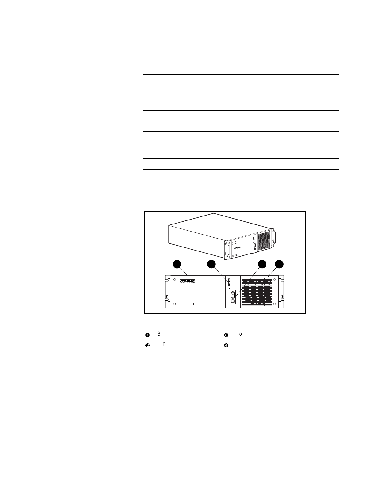
Front Panels
The 3000 Series UPS models are rack-mountable.
Table 1-1
non-detachable IEC-309 15A power cord
11 2 3 4
Figure 1-1. Front panel configuration
Battery compartment
1
LED display
2
Control buttons
3
Air vents
4
Page 14
Rear Panels
The 3000 Series UPS models feature the following rear pane l configurations:
Overview 1-3
18
2 3
7
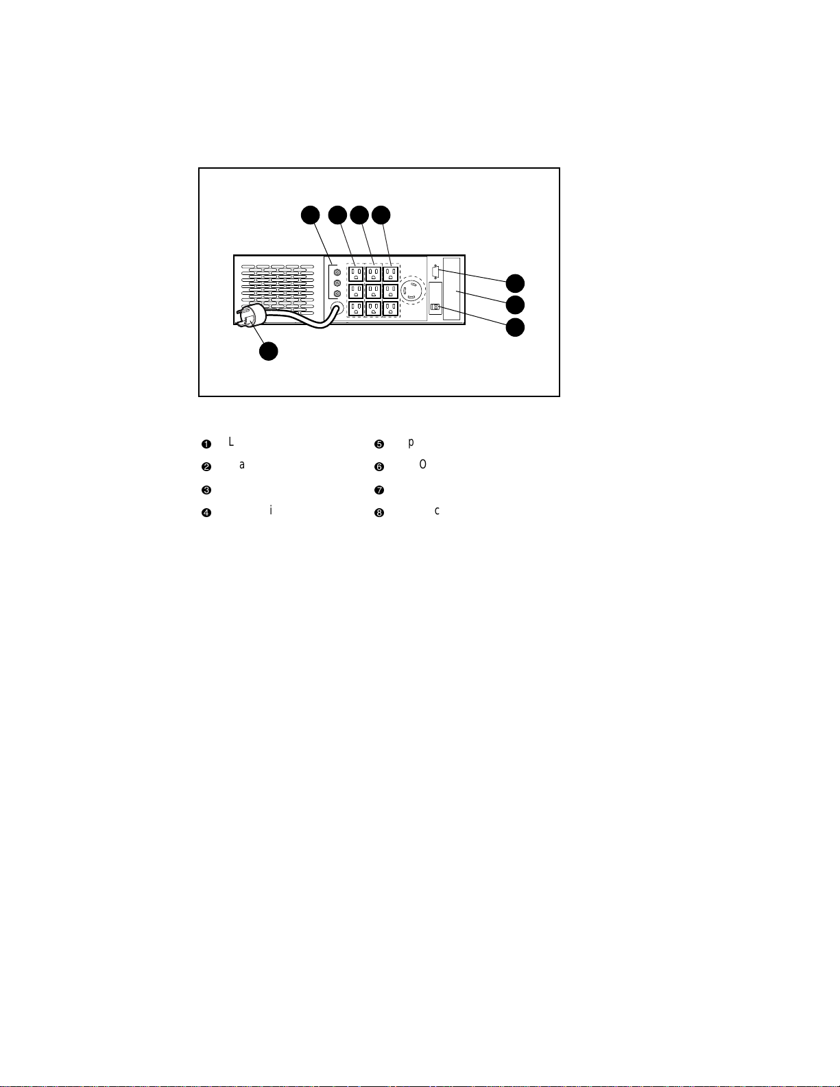
Figure 1-2. Rear panel of R3000
Load segment 1
1
Load segment 2
2
Load segment 3
3
Communications port
4
REMOTE
POWER OFF
Option slot
5
REPO port
6
Power cord with L5-30p plug
7
Output circuit breakers
8
4
5
6
Page 15
1-4 Compaq 3000 Series UPS Operation and Reference Guide
8
1 2 3
7
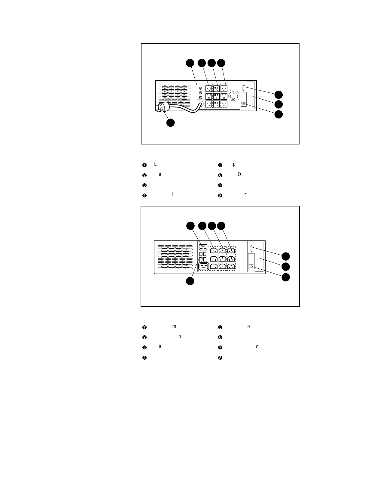
Figure 1-3. Rear panel of R3000j
Load segment 1
1
Load segment 2
2
Load segment 3
3
Communications port
4
18
2 3
REMOTE
POWER OFF
Option slot
5
REPO port
6
Power cord with L6-30p plug
7
Output circuit breakers
8
REMOTE
POWER OFF
4
5
6
4
5
7
Figure 1-4. Rear panel of R3000h
Load segment 3
1
Load segment 2
2
Load segment 1
3
Communications port
4
Option slot
5
REPO port
6
Input/Output circuit breakers
7
IEC-320-C19 16A power inlet
8
6
Page 16
Overview 1-5
18
2 3
7
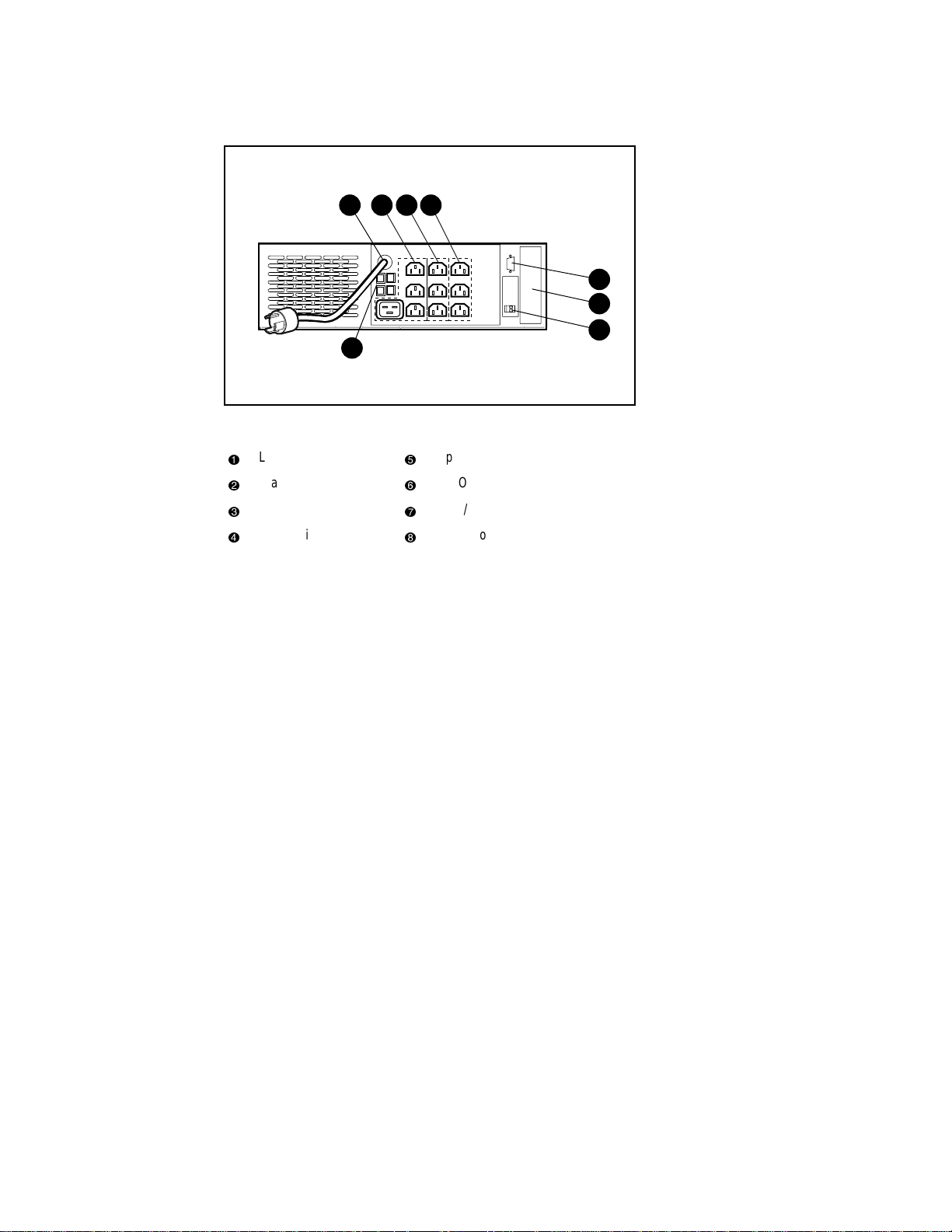
Figure 1-5. Rear panel of R3000h-International
Load segment 3
1
Load segment 2
2
Load segment 1
3
Communications port
4
Option slot
5
REPO port
6
Input/Output circuit breakers
7
Power cord with IEC-309 15A plug
8
REMOTE
POWER OFF
4
5
6
Page 17
1-6 Compaq 3000 Series UPS Operation and Reference Guide
18
2 3
7
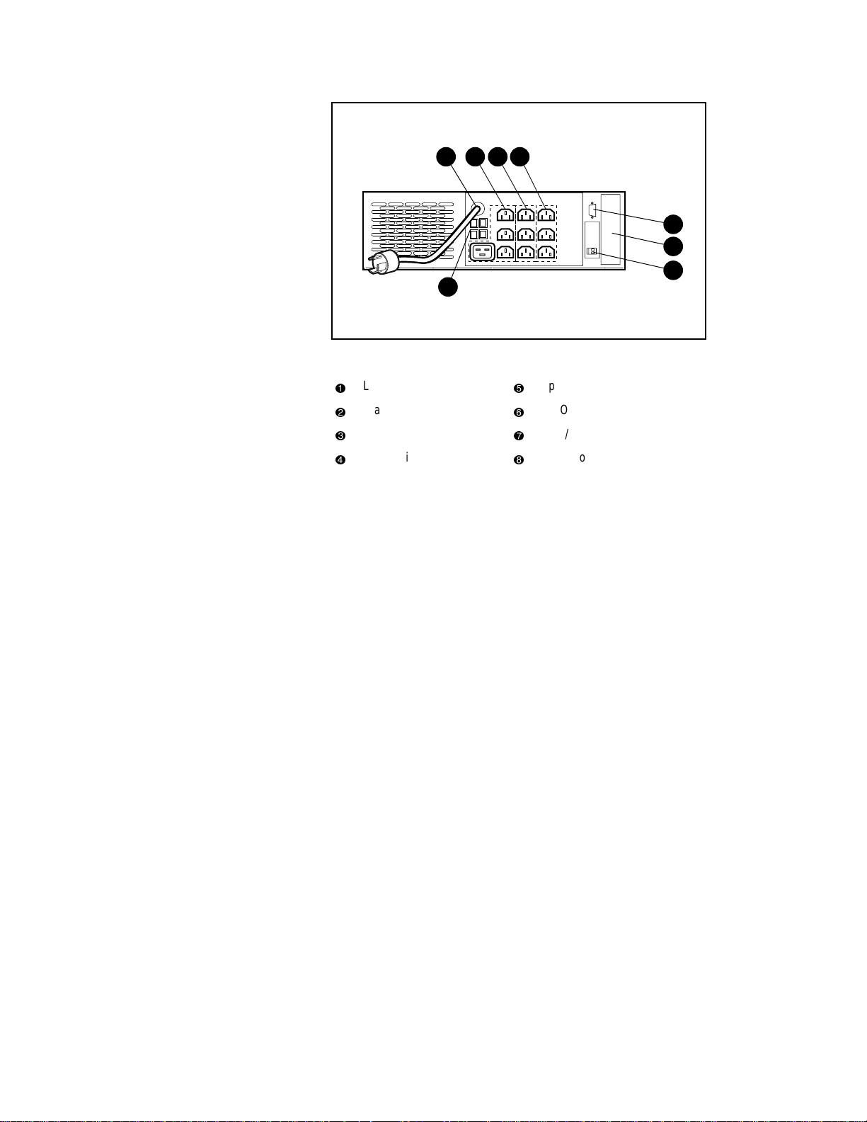
Figure 1-6. Rear panel of R3000h-NA
Load segment 3
1
Load segment 2
2
Load segment 1
3
Communications port
4
Standard UPS Features
The 3000 Series UPS models pr ovide the following features:
■ Communicat ions port for data exchange with the host computer
■ Power protection for loads up to 3000VA
■ Load segment control
REMOTE
POWER OFF
Option slot
5
REPO port
6
Input/Output circuit breakers
7
Power cord with L6-30p plug
8
4
5
6
■ Support for power management software
■ Support for Compaq hardware option cards, extending the power
management capabilities of the UPS
■ Support for Remote Emergency Power Off (REPO) circuitry
Page 18

Communications Port
The 3000 Series UPS includes a communications port for data exchange with
the host computer. The p ower management software supplied by Compaq
enables the user to access status reporting and power management features.
CAUTION: Use only cables supplied by Compaq to connect the communications
port to the host computer. Use of standard RS-232 cables may cause equipment
damage.
Power Management Software
With each UPS, Compaq supplies a CD containing several power management
software applications, to address a variety of installations:
■ Compaq Power Management Software is a comprehens ive Microsoft
Windows-based power management appli cation that is t ightly integrated
with Compaq Insight Manager.
■ LanSafe III provides UPS power management capabilities in a network
environment.
■ FailSafe III provides UPS power management capabilities in a
standalone computer environment.
Overview 1-7
■ Compaq OnliNet Centro provides UPS power manageme nt capabilities
in a multi-platform network environment (supplied only with the
Compaq SNMP-EN Internal Adapter).
Page 19

1-8 Compaq 3000 Series UPS Operation and Reference Guide
Compaq Power Management Software
Compaq Power Management Software allows system administrators to
monitor, and to manage, t he power bei ng supplied to an entire network of
servers and wor kstations.
Software capabilities include:
■ Monitoring utility power, and the power supplied by the UPS.
■ Logging events, such as utility power blackouts and brown outs.
■ Prioritizing protected devices.
■ Powering up and pow er i ng d own pr o te cte d de vic es .
For example, if Compaq Power Management Software detects an extended
utility power blackout, it will initiate the prioritized shutdown sequence
specified by the system administrator.
This sequence might include:
■ Saving work-in-progress throughout the network.
■ Powering down non-critical devices, to extend the battery power
available to other devices.
■ After savi ng the necessary informatio n, completin g t he orderly de vice
shutdown.
For more information on using Compaq Power Management Software, refer to
the Compaq Power Products Software Reference Guide section of the Power
Products Doc umentation CD (included with the UPS kit).
Hardware Option Cards
The 3000 Series UPS include an option slot that will accommodate one of
these hardware opt io n ca rd s:
■ Compaq Multi -Server UPS Card (option kit part number 1235 08-B21)
■ Compaq Scalable UPS Card (option kit part number 123509-B21)
■ Compaq SNMP- EN Internal Adapter (opti on kit part number
347225-B21)
Page 20

Overview 1-9
Compaq Multi-Server UPS Card
A standard UPS can communicate directly with a single host computer. The
Multi-Server UPS Card expands the communications capability of the UPS so
that a single UPS that can exchange data with up to three host computers.
Compaq Power Management Software enables a single UPS wit h a
Multi-Server UPS Card to protect up to three servers. Individual server control
can be obtained by connecting the servers to different UPS load segments.
For example, if a network includes three servers (with one running Windows
NT, one running Unix, and one running NetWare), a Multi-Server Card can be
used to establish direct communications between the UPS and all three servers.
Use a single UPS load segment to supply power to a particular server and to
the devices associated with that server.
Compaq Scalable UPS Card
The Scalable UPS Card makes up to three UPS units appear as a single virtual
UPS to the host computer and, wi th Compaq Power Management Software,
allows scaling up the level of power protection available to the system.
For example, connecting three R3000 UPS units to a Scalable UPS Card
creates a virtual 9000VA UPS. Since the R3000 UPS each have three load
segments, the virtual UPS will have nine independe ntl y contro lled load
segments.
However, no single load can be greater than the lowest rated UPS. For
instance, connecting three 1KVA UPSs with a Scalable UPS Card could not
support a single 1200VA load.
Page 21

1-10 Compaq 3000 Series UPS Operation and Reference Guide
Compaq SNMP-EN Internal Adapter
In a network environment, the SNMP-EN Internal Adapter provides a user
interface, allowing communication between the UPS and the server (when the
SNMP-based power management software, Compaq OnliNet Centro, is
installed). For workstations or other peripheral equipment that cannot be
interrupted by a network ma nagement system, a UPS with t he SNMP-EN
Internal Adapter option installed can also provide a power management
solution.
Using the SNMP-EN Internal Adapter SNMP communication interface,
system administrators can quickly ascertain if power-related problems exist
anywhere on the network. A Compaq UPS, connected by an SNMP-EN
Internal Adapter to power management software, can virtually eliminate costly
downtime due to power outages or surges, and decrease day-to-day network
management annoyances like spontaneous rebooting, lost files and corrupted
data—issues resulting from inconsistent power.
Compaq OnliNet Centro software is a versatile application that can schedule
network component shutdowns or, in case of a utility power outage, perform
graceful, sequential shutdown of network components.
Remote Emergency Power Off (REPO) Port
The 3000 Serie s UPS models include a Remote Emergency Power Off
(REPO) port. The REPO feature allows the UPS to be shut down from a
remote location. To use this feature, the REPO port must be connected to a
remote, normally open switch (not suppl i ed). When this switch is closed, the
UPS immediately disconnects power from its load segments.
To shut down the entire network in the event of an emergency, the REPO ports
of multiple UPS units can be connected to a single switch.
IMPORTANT: The REPO port meets the requirements of NFPA Articles 645-10 and
645-11 for a Disconnecting Means.
IMPORTANT:
■ If the remote switch is closed, the REPO feature shuts down protected devices
immediately and does not utilize the orderly shutdown procedure initiated by
Compaq Power Management Software.
■ The REPO feature shuts down UPS units operating under either utility or
battery power.
■ If the UPS was operating on battery power when the remote switch was closed, no
power will be available to the devices until utility power is restored.
Page 22

Warranties
$25,000 Computer Load Protection Guarantee
To back up the wide range of features offe red with the UPS, Compaq provides
a three-year limited warranty. In addition, Compaq offers a $25,000 Computer
Load Protection Guarantee (provided by the original equipment manufacturer).
IMPORTANT: The warranty card supplied with the UPS must be filled in and returned to
qualify for the $25,000 Computer Load Protection Guarantee.
The $25,000 Computer Load Protection Guarantee only applies if:
■ The UPS is plugged into a sui tably grounded and wired out let using no
extension cords, adapters, other ground wires, or other electrical
connections.
■ The UPS installation complies with all applicable electrical and saf ety
codes specified by the National Electrical Code (NEC).
■ The UPS is used under normal operating conditions. Users comply with
all instructions and labels.
Overview 1-11
■ The UPS is not damaged by accident (other than a utility power
transient), misuse, or abuse.
Pre-Failure Battery Warranty
The Pre-Failure Battery Warranty, standard on all Compaq Uninterruptible
Power System (UPS) units, extends the advantage of a Compaq three-year
limited warranty by applying it to the battery before it actually fails.
Specifically, the Pre-Failure Battery Warranty ensures that when customers
receive notification from Compaq Power Management Software that the
battery ma y fail, the battery is replaced free of charge under the warranty.
Compaq maintains the highest standards in the industry, as evidenced by the
Compaq Pre-Failure Battery Warranty. The Pre-Failure Battery Warranty is
beneficial in at least two significant ways:
■ Reduced total cost of ownership
■ Reduced downtime
Page 23

This chapter pro vides information on the followi ng topics:
■ Installation requirements
■ Procedures to complete before starting the UPS
■ Starting the UPS
■ Completing the installatio n
Chapter
2
Installation
Page 24

2-2 Compaq 3000 Series UPS Operation and Reference Guide
Installation Requirements
This section lists items needed to install the Compaq 3000 Series UPS models.
Item(s) not supplied with the UPS kit
Tools
A medium flat- bladed and Phillips screwdriver may be needed.
Other Hardware
A number of screws, cage nuts, and a cage nut-fittin g tool (supplied with the
rack) are required.
Item(s) supplied with the UPS kit
The UPS kit should contain the following components:
Software/Refe ren ce Mat erial
■ The Power Products Documentation CD containing the 3000 Series UPS
Operation and Reference Guide and the Compaq Power Products
Software Reference Guide
■ The Compaq Power Management Software Installation Instru ctions (a
booklet included with the CD) containing information on the installa tion
requirements for Compaq Power Management Software
■ Important Safety Information to be reviewed before installi ng this product
Hardware
The UPS ships with one or more of the following:
■ Depth-adjustable fixed rails kit
■ Front handles and mounting brac kets (2)
■ REPO terminal and connector block
Page 25

Installation 2-3
■ Cable(s)
q
The R3000 and R 3000j models ship w i th a non-detacha ble input
power cord; a 6-foot UPS/computer interface cable, Compaq part
number 295245-004; and two 10-amp, 6-foot, IEC to IEC powe r
cords, Compaq part number 142263-001, f or load equipment power.
q
The R3000h, R3000h-Interna tional, and R3000h-NA models ship
with a non-detachable input power cord (the R300 0h model only
ships with a detachable input power cord); a 12-foot UPS/computer
interface cable, Compaq part number 295245-004; two 10-amp,
6-foot, IEC to IEC power cords, Compaq part number 142263-001;
two 8-foot IEC to IEC power cords, Compaq part number
142263-002; and two 10-foot IEC to IEC power cords, Compaq part
number 142263-003, for load equipment pow er.
All models ship with a computer interface cable. The computer interface cable
is not needed for normal operation. If power management of the UPS is
desired, connect the interface cable between the UPS communications port and
the serial port on the host computer.
IMPORTANT: If the UPS does not include a power cord that is suitable for your
application, contact an authorized Compaq service representative to obtain the
appropriate power cord. Please refer to the “Precautions for Power Products” section of
the Important Safety Information (included with the UPS kit).
Before Starting the UPS
This section provides installatio n steps to be completed before starti ng the
UPS.
Determine the steps required for the application:
■ Rack-mounting the UPS
■ Connecting the UPS communications port to the host computer
■ Connecting the Remote Emergency Power Off
NOTE: Although these steps can be carried out after the UPS is installed, the UPS will
need to be powered down to safely perform these tasks.
Page 26

2-4 Compaq 3000 Series UPS Operation and Reference Guide
Rack Mounting the UPS
The 3000 Series U PS models must be mounted on fixed r ails. Refer to the
appropriate installation card (sup plied with the UPS kit) to obtain instr uctions.
WARNING: The 3000 Series UPS models weigh 132 lb (60 kg). To reduce the
risk of personal injury or damage to the equipment, take the following
precautions:
■ The 3000 Series UPS models MUST be installed at the bottom of the rack.
If placed in the rack with existing equipment, the rack must be reconfigured to allow installation of the UPS at the bottom of the rack.
■ Do not use slides to mount the UPS in the rack.
■ Use the fixed rails supplied in the installation kit.
■ Use a minimum of two people to place the UPS on the rails.
WARNING: Make sure that the rack containing the UPS is stable. The following
conditions must be met:
■ The leveling feet are extended to the floor.
■ The full weight of the rack rests on the leveling feet.
■ The stabilizing feet are attached to the rack, if it is a single rack
installation.
■ The racks are coupled together in multiple rack installations.
■ A rack may become unstable if more than one component is extended for
any reason. Extend only one component at a time.
Page 27
Connecting to the Communications Port
The 3000 Series UPS models include a communications port for data
exchange with the host computer.
IMPORTANT: Compaq Power Management Software, LanSafe III, and FailSafe III require
the communications port to be appropriately cabled to the host computer.
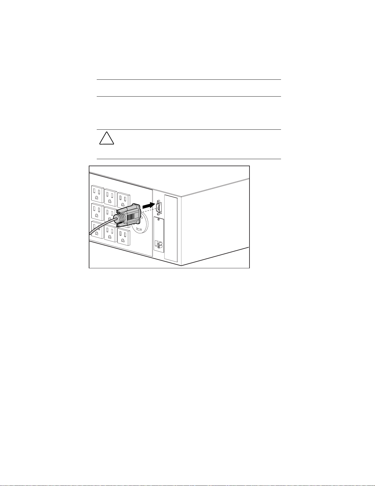
Connect the UPS/computer interface cable (supplied) from the
communications port on the UPS to the appropriate communications port on
the host computer.
CAUTION: To avoid damaging the equipment, do not use the communications
cables (part numbers 142260-001 and 142260-002) supplied with earlier UPS
models. The UPS/computer interface cable is required to carry power and is
wired differently than earlier communications cables.
Installation 2-5
REMOTE
POWER OFF
Figure 2-1. Connecting the UPS/computer interface cable
Connecting the Remote Emergency Power Off
The 3000 Series UPS models include a Remote Emergency Power Off
(REPO) port. When properly wired, the REPO port allows the power to the
UPS output receptacles to be switched off from a remote location.
Page 28
2-6 Compaq 3000 Series UPS Operation and Reference Guide
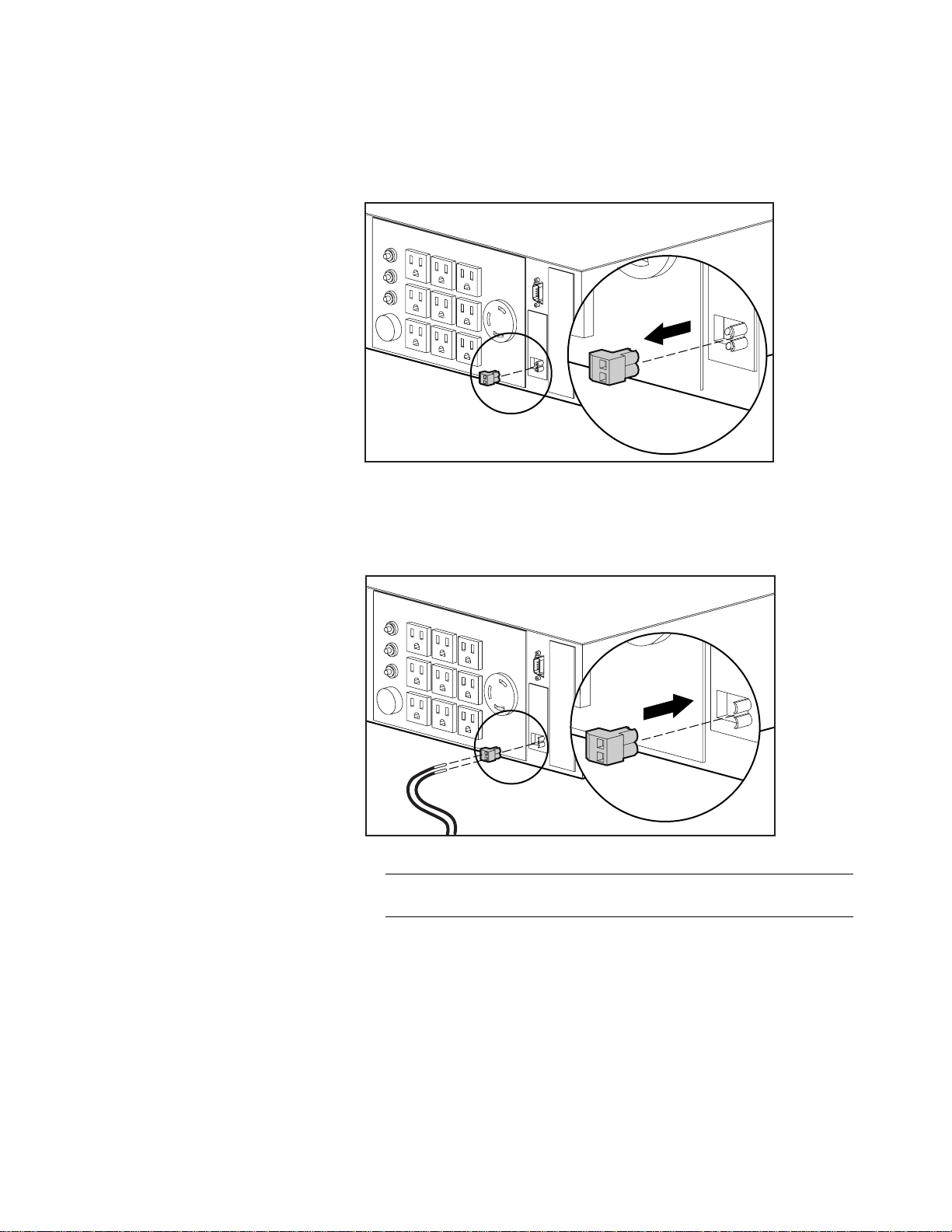
Use this procedure to activate the REPO port:
Install a suitable switch at the required remote location.
1.
Remove the connector bloc k from the REPO por t.
2.
REMOTE
POWER OFF
Figure 2-2. Removing the connector block
Wire the connector block using stranded, non-shielded wi re
3.
(AWG #22 - #18, or equivalent).
Replace the connector block in the REPO port.
4.
REMOTE
POWER OFF
Figure 2-3. Replacing the connector block
IMPORTANT: The remote switch must be in the OFF (open) position to enable power to
the output receptacles.
Page 29

Starting the UPS
Starting the UPS for the first time requires the follow ing procedures:
■ Checking the Battery Recharge Date label on the UPS shipping carton
■ Connecting the UPS to utility p ower via the input power cord
■ Connecting devices to the UPS
■ Powering u p the UPS
■ Monitoring the automatic self-test to verify that the installation was
successful
Checking the Battery Recharge Date Label
Check the battery recharge date specified on the Battery Recharge Date label.
This label is affixed to the UPS ship ping carton.
IMPORTANT: Do not use the UPS if the battery recharge date has expired. If the date on
the Battery Recharge Date label has passed without the batteries being recharged,
contact an Authorized Compaq Service Representative.
Installation 2-7
THIS PRODUCT CONTAINS
A NONSPILLABLE BATTERY
Next Recharge Date:
14-DEC-04
Please refer to Maintenance Section
of Owner's Manual enclosed inside
Figure 2-4. The Battery Recharge Date label
Page 30

2-8 Compaq 3000 Series UPS Operation and Reference Guide
Connecting the UPS to Utility Power
Connect the UPS to a grounded utility power outlet.
WARNING: To reduce the risk of electric shock or damage to the equipment,
take these precautions:
■ Plug the input line cord into a grounded (earthed) electrical outlet that is
installed near the equipment and is easily accessible.
■ Do not disable the grounding plug on the input line cord. The grounding
plug is an important safety feature.
■ Do not use extension cords.
Connecting Devices to the UPS
Before connecting devices, verify tha t the UPS will not overload by maki ng
sure that the total VA rating of the devices (the load) does not exceed the VA
rating of the UPS.
Volts x Amps = VA per device
If the devices list the power in Watts, use t he following conversion equation:
Watts x 1.35 = VA
VA/1000 = KVA
You may use RackBuilder Pro as an a lternate conversion tool. RackBuilder
Pro may also be obtained from the C ompaq website:
http://www.compaq.com
After verifying that the UPS will not overload, connect the power cords from
the devices to the appropriate output receptacles of the UPS.
WARNING: To reduce the risk of electric shock, the combined earth conductor
leakage current from all connected devices must not exceed 3.5 mA.
CAUTION: Do not plug laser printers into the UPS. The instantaneous current
drawn by this type of printer may overload the UPS.
IMPORTANT: To provide additional receptacles, plug a Compaq Power Distribution Unit
(PDU) into the high current receptacle associated with load segments 1, 2, or 3. To
connect the devices to the PDU, use IEC-320 jumper cords (part number 295633-B21).
Page 31

Powering up the UPS
When the unit is plugged in for the first time, the UPS automatically initiate s a
self-test. The front panel LED display lights will go on and off during the selftest. If the self-test is completed successfully, the UPS enters Standby mode.
NOTE: The self-test initiates when the UPS is plugged in for the first time. Afterward,
when the UPS is disconnected from utility power, the unit will come back up in the mode
it was in when utility power was lost.
Installation 2-9
5 4 3 2 1
10 9 8 7 6
15 14 13 12 11
16171819
Figure 2-5. The front panel LED display and controls
1–4
6–9
q–r
AC Input level Power cord
Site Wiring Fault indicator
5
Battery Charge level Battery
Battery Service indicator
:
Load level Load devices
Communications
t
ON LED
y
ON button
A
STANDBY button
i
TEST/ALARM RESET button
C
Symbol
Page 32

2-10 Compaq 3000 Series UPS Operation and Reference Guide
Check the front panel LED displa y:
■ LED 16 (ON LED,
@
) should be off, indicating that no power is
available at the UPS output receptacles.
■ Either AC Input LED 2 or 3 should be green, indicating the utility
voltage is suitable.
■ LEDs 6, 7, 8, and 9 indicate the ba ttery charge level.
q
LED 9 warns that the batteries are low—approximately three to five
minutes of battery backu p rem ain
q
LED 8 only = 33 percent charged
q
LEDs 7 and 8 = 66 percent charged
q
LEDs 6, 7, and 8 = 67 percent to 100 percent char ged
For more information on the fro nt panel LED display, see Chapter 3,
“Operation.”
IMPORTANT: If any of the LEDs on the front panel are red (indicating an alarm condition),
press the TEST/ALARM RESET button to clear the red LEDs. If this does not clear the red
LEDs, see Chapter 6, “Troubleshooting.”
Red LEDs may be accompanied by an audio alarm. For information on silencing the alarm,
see Chapter 3, “Operation.”
Completing the Installation
With the UPS in Standby mode, allow the batteries to charge before putting
the UPS into service.
IMPORTANT: The batteries will charge to 90% of their capacity within approximately
4 hours. Compaq recommends allowing the batteries to charge for 24 hours before using
them to supply backup power to devices.
Page 33

Placing the UPS in Operate mode
Press and hold the ON button (2) until the LED 16 (1, ON LED) turns green,
indicating that power is available at the UPS output receptacles. The UPS will
acknowledge compliance with a short beep.
Figure 2-6. Operate mode controls
Installation 2-11
1
2
3
1
2
ON LED
ON button
STANDBY button
3
The Installation is Now Complete
■ For information on operating th e UPS, see Chapter 3, “Operation.”
■ For information on changin g the configurat ion of the UPS, se e
Chapter 4, “Configuration.”
■ Use the Compaq website as an additional information source:
http://www.compaq.com
Page 34

This chapter contains information on the following topics:
■ Precautions to be observed when using the UPS
■ UPS modes of oper ation
■ Front panel controls
■ Front panel indic ators
■ Overcurrent protection
■ Placing the UPS in Operate mode
Chapter
3
Operation
■ Returning to Standby mode
■ Initiating a self-test
■ The audio alarm
Page 35

3-2 Compaq 3000 Series UPS Operation and Reference Guide
Precautions
Observe these precautions when using the Compaq 3000 Series UPS models.
WARNING: To reduce the risk of electric shock from earth conductor leakage
current:
■ Do not operate a UPS that is disconnected from the utility power source.
■ Disconnect protected devices from the UPS before disconnecting the UPS
from utility power.
■ Use the TEST/ALARM RESET button to test the batteries rather than
unplugging the UPS. See “Initiating a Self-test” in this chapter for more
information.
Modes of Operation
The 3000 Series U PS models have four modes of oper ation:
Standby Mode
■ No power is available at the UPS output receptacles.
■ The UPS charges the batteries as necessary.
Operate Mode
■ Power is available at the UPS output receptacles.
■ The UPS charges the batteries as necessary.
Configure Mode
■ Power is available at the UPS output receptacles.
■ The UPS charges the batteries as necessary.
■ The user can update the UPS configuration.
NOTE: For more information on configuring the UPS, see Chapter 4, “Configuration.”
Page 36

Operation 3-3
Sleep Mode
By default, Sleep mode is disable d.
When Sleep mode is disabled:
■ If the batteries have been fully discharged, power may not be
automatically restored to the output receptacles when utility power is
restored.
CAUTION: The UPS Sleep mode default setting is OFF (disabled). When Sleep
mode is OFF (disabled), if the UPS is supplying battery power, the batteries can
be fully discharged before the UPS will shut down. If the batteries become fully
discharged, they may be unrecoverable (damaged).
NOTE: For information on enabling Sleep mode, see Chapter 4, “Configuration.”
When Sleep mode is enabled:
■ If the UPS is supplying battery power and the load on the UPS is less
than 10 percent, the UPS shuts down.
■ Power is automatically restored to the output receptacles when utility
power is restored.
Front Panel Controls
The 3000 Series UPS front panel includes the controls required to:
■ Place the UPS in Operate mode.
■ Place the UPS in Standby mode.
■ Place the UPS in Configure mode.
■ Initiate a self-test.
■ Silence an audio alarm.
NOTE: For information about changing the configuration on the UPS, or simply checking
the current configuration, see Chapter 4, “Configuration.”
Page 37

3-4 Compaq 3000 Series UPS Operation and Reference Guide
The front panel includes the following LED indicators and button controls:
16171819
Figure 3-1. The front panel LED display and controls
5 4 3 2 1
10 9 8 7 6
15 14 13 12 11
Symbol
1–4
5
6–9
:
q–r
t
y
A
i
C
AC Input level Power cord
Site Wiring Fault indicator
Battery Charge level Battery
Battery Service indicator
Load level Load devices
Communications
ON LED
ON button
STANDBY button
TEST/ALARM RESET button
Page 38

Front Panel Indicators
The front panel LED display colors indicate the UPS status:
■ Green LEDs indicate normal conditions
■ Red LEDs provide warning of existing or potentia l problems
LEDs are referred to as LED 1 through 16, as described in this documentation.
When the UPS is in Configure mode, the LEDs do not operate as they do in
the Standby and Operate modes (see Chapter 4, “Configuration”).
Front Panel LEDs in the
Standby and Operate Modes
Each LED (and the condition it indicates in the Operate and Standby modes) is
described in t he following table s:
AC Input (LEDs 1-4)
Operation 3-5
Table 3-1
AC Input LEDs
LED Color Meaning
1 Red The utility voltage is higher than the voltage range for which the
UPS has been configured. The UPS is supplying battery power.
The audio alarm will sound.
Flashing Red Utility voltage has returned to the voltage range for which the UPS
has been configured. The UPS is supplying utility power. The
audio alarm should be reset.
2 Green Utility voltage is within the voltage range for which the UPS has
been configured.
3 Green Utility voltage is lower than the current UPS configuration expects.
The UPS is compensating and providing power to the loads
without the use of batteries.
4 Red The utility voltage is lower than the voltage range for which the
UPS has been configured. The UPS is supplying battery power.
The audio alarm will sound.
Flashing Red Utility voltage has returned to the voltage range for which the UPS
has been configured. The UPS is supplying utility power. The
audio alarm should be reset.
Page 39

3-6 Compaq 3000 Series UPS Operation and Reference Guide
Site Wiring Fault (LED 5)
Site Wiring Fault LED
LED Color Meaning
5 Red No ground connection between utility power and the UPS.
The line and neutral connections between utility power and the
UPS are reversed.
The UPS voltage configuration may be incorrect.
Note: For units factory-configured for 208V, the Site Wiring Fault function has been
disabled. If reconfiguring a 230V unit to operate at 208V, the Site Wiring Fault function
must be manually disabled. See the section “Changing Configuration Parameters” in
Chapter 4, “Configuration.”
Battery Charge (LEDs 6-9)
Battery Charge LEDs
Table 3-2
Table 3-3
LED Color Meaning
6 Green Batteries are between 67% and 100% charged.
(LEDs 7 and 8 are also green)
7 Green Batteries are approximately 66% charged.
(LED 8 is also green)
8 Green Batteries are approximately 33% charged.
9 Red Batteries are low; approximately three to five minutes of battery
backup remain.
Battery Service (LED 10)
Table 3-4
Battery Service LED
LED Color Meaning
10
Note: When LED 10 is red, the audio alarm will sound, indicating the UPS has detected a
potential battery failure. The UPS batteries may need to be replaced in 30 to 60 days.
Red Potential battery failure.
Page 40

Load Level (LEDs 11-14)
Table 3-5
Load Level LEDs
LED Color Meaning
11 Red Load on the UPS exceeds the maximum power available.
12 Green Load on the UPS is approximately 67% to 100% of the
maximum power available.
(LEDs 13 and 14 are also green)
13 Green Load on the UPS is approximately 66% of the maximum power
available.
(LED 14 is also green)
14 Green Load on the UPS is approximately 33% of the maximum power
available.
Communication (LED 15)
Table 3-6
Communication LED
Operation 3-7
LED Color Meaning
15 Green The communication link between the UPS and the host
computer is active.
Flashing
Green
Data is being transferred between the UPS and the host
computer.
On (LED 16)
If LED 16 is green, power is available at the UPS output receptacles.
Page 41

3-8 Compaq 3000 Series UPS Operation and Reference Guide
Overcurrent Protection
Overcurrent protection is provided via r esettable circuit breakers located on
the rear panel. The following models have overcurrent prot ection:
Overcurrent Pro tection
UPS Model Device
R3000 Circuit breaker for each load segment
R3000j Circuit breaker for each load segment
R3000h Input circuit breaker
R3000h-Int Input circuit breaker
R3000h-NA Input circuit breaker
Table 3-7
Circuit breaker for each load segment
Circuit breaker for each load segment
Circuit breaker for each load segment
Page 42

Placing the UPS in Operate Mode
The Compaq 3000 Series UPS may be placed in Operate mode if either of the
following conditions apply:
■ The UPS is powered up and in Standby mode (LED 16 is off)
■ The UPS is powered off; no utility power is available
2
Press and hold the ON button (
) until the LED 16 (ON LED 1) turns green,
indicating that power is available at the UPS output receptacles. The UPS
acknowledges compliance with a short beep.
IMPORTANT: If using battery power (no utility power present), press the ON button and
hold for three seconds. The UPS will conserve battery power by omitting the self-test.
Operation 3-9
1
2
Figure 3-2. Operate mode controls
ON LED
1
ON button
2
STANDBY button
3
3
Page 43

3-10 Compaq 3000 Series UPS Operation and Reference Guide
Returning to Standby Mode
When the UPS is in Operate mode (LED 16, 1, is green), pressing the
2
STANDBY button (
acknowledge compliance with a short beep. LED 16 (
power to the loads will cease.
) will place the UPS in Standby mode. The UPS will
1
) will extinguish, and
1
2
Figure 3-3. Standby mode controls
ON LED
1
STANDBY button
2
IMPORTANT:
■ While in Standby mode, the UPS maintains the charge on the batteries, but no power
is available at the output receptacles.
■ The UPS remains in Standby mode until an alternate mode is selected, or until utility
power is removed.
Page 44

Initiating a Self-test
To initiate a self-test, press the TEST/ALARM RESET button and hold for
three seconds. The UPS acknowledges compliance with five beeps.
Figure 3-4. The TEST/ALARM RESET button
Operation 3-11
1
TEST/ALARM RESET button
1
IMPORTANT: A portion of the self-test requires battery power; the self-test cannot be
initiated if the batteries are less than 90% charged.
During the self-test, it is normal for the UPS to turn on individual LEDs
momentarily; however, if an alarm condition is detected, the UPS will turn on
the appropriate LED and may sound an audio alarm.
WARNING: To reduce the risk of electric shock from earth conductor leakage
current, use the self-test procedure to check the UPS batteries (rather than
unplugging the UPS).
■ For the meaning of individual LE Ds, see “Front Pa nel LEDs in the
Standby and Operate Modes,” in this chapter.
■ For information on what to do if the self-test detects a problem, see
Chapter 6, “Tro ubleshooting.”
Page 45

3-12 Compaq 3000 Series UPS Operation and Reference Guide
Audio Alarm
The UPS may sound an audio alarm to warn the user that an alarm condition
exists.
IMPORTANT: Certain audio alarms can be disabled. See Chapter 4, “Configuration,” for
more information.
Audio Alarm Conditions
Alarm Condition LED Activity Can be disabled?
Utility power failure LED 1 or LED 4 red Yes
Site Wiring Fault LED 5 on red Yes
Battery Service LED 10 on red Yes
Internal UPS overvoltage LED 10 flashing red No
Silencing an Audio Alarm
Table 3-8
To silence the alarm, press the TEST/ALARM RESET button.
1
Figure 3-5. The TEST/ALARM RESET button
TEST/ALARM RESET button
1
Page 46

Operation 3-13
IMPORTANT:
■ Even though an audio alarm may be silenced, the condition that caused the alarm
may still exist. For information on procedures to follow if the UPS detects an alarm
condition, see Chapter 6, “Troubleshooting.”
■ If a utility power failure caused the alarm (AC Input LED 1 or LED 4 red), the alarm
will be silenced after utility power is restored.
Page 47

Chapter
Configuration
This chapter contains information on the following topics:
■ Placing the UPS in Configure mode
■ Configuration parameter s and their LED indicators
■ Using the front panel LED display and controls to m onitor and change
configuration pa ra me ter s
■ Using the UPS configuration p a rameters to optimize battery life by
matching utility voltage
4
Page 48

4-2 Compaq 3000 Series UPS Operation and Reference Guide
Placing the UPS in Configure Mode
The Compaq 3000 Series UPS can enter the Configure mode while in the
Operate or Sta ndby mode.
Figure 4-1. Configure mode controls
ON LED (LED 16)
1
ON button
2
STANDBY button
3
TEST/ALARM RESET button
4
1
2
3
4
To place the UPS in Configure mode, press the ON (2) and TEST/ALARM
4
RESET (
) buttons simultaneously. Release the buttons when the
acknowledge me nt beep sounds.
IMPORTANT: If the STANDBY button is pressed while in the Configure mode, the UPS will
enter Standby mode, and power to the load segments will cease.
In the Configure mode, the front panel LED display changes functi on. The
LED display and button controls allow the user to monitor, and to change , the
UPS configuration parameters.
Page 49

Configuration Parameters
and their LED Indicators
Configuration 4-3
In the Configur e mode, the front panel LEDs 1 t o 15 are assigned to eleven
configuration pa ra me ter s
1
, detailed in the following table. (LED 16 indicates
the ON or OFF status of each parameter.)
5 4 3 2 1
10 9 8 7 6
15 14 13 12 11
16171819
Figure 4-2. The front panel LED display and controls
1
Configuration parameters 11 to 14 are reserved for future use.
Page 50

4-4 Compaq 3000 Series UPS Operation and Reference Guide
Configuration Parameters/LED Indicators
Table 4-1
Parameter
(LED)
Parameter
Name
1 120/230 Nom On
2 110/220 Nom On
3 127/240 Nom On
10 100/208 Nom On
4 Extended
Voltage
LED 16
Explanation
Status
1
Nominal utility voltage level is
120/230 VAC.
(Default for R3000, R3000h,
and R3000h-Int)
1
Nominal utility voltage level is
110/220 VAC.
1
Nominal utility voltage level is
127/240 VAC.
1
Nominal utility voltage level is
100/208 VAC.
(Default for R3000j and R3000h-NA)
On UPS will supply utility power if the utility
voltage is within +20% to –35% of the
nominal voltage. If the utility voltage is
outside this range, the UPS will supply
battery power.
(This option not available on the R3000j
and R3000h-NA)
Off
(default)
UPS will supply utility power if the utility
voltage is within ±20% of the nominal
voltage. If the utility voltage is outside this
range, the UPS will supply battery power.
5 Wiring
Fault
6 Low
Battery
On
(default)
Enables an audio alarm if ground is
missing, or if line and neutral connections
have been reversed.
(This option not available on the R3000j
and R3000h-NA)
Off Disables the audio alarm for this event.
(Default for R3000j and R3000h-NA)
On
(default)
Enables an audio alarm 3 minutes before
battery shutdown.
Off Enables an audio alarm 5 minutes before
battery shutdown.
continued
Page 51

Table 4-1
Configuration Parameters/LED Indicators
Parameter
(LED)
Parameter
Name
LED 16
Status
Configuration 4-5
continued
Explanation
7 Shutdown
Delay
On
(default)
Enables a 5-second delay before turning
off power to the output receptacles after
receiving a shutdown command from the
host.
Off Enables a 3-minute delay.
8 AC Input Failure On
(default)
Enables an audio alarm when the utility
voltage is outside the UPS operating range.
Off Disables the audio alarm for this event.
9 Sleep Mode On Enables Sleep mode.
Off
Disables Sleep mode.
(default)
11-14 Reserved Reserved for future use.
15 Reset Defaults On Defaults are restored2.
Off Configuration selected by the user
overrides defaults.
Notes: 1 Only one nominal utility voltage can be configured.
2
If model R3000j voltage defaults to 120, change the voltage to 100.
If model R3000h-NA voltage defaults to 230, change the voltage to 208.
Page 52

4-6 Compaq 3000 Series UPS Operation and Reference Guide
Changing Configuration Parameters
The Configure mode may be entered from the Operate or Standby mode.
IMPORTANT: If the STANDBY button is pressed while in the Configure mode, the UPS will
enter Standby mode, and power to the load segments will cease.
1
2
3
4
Figure 4-3. Configure mode controls
ON LED (LED 16)
1
ON button
2
STANDBY button
3
TEST/ALARM RESET button
4
To change co nfiguration parameters:
2
Place the UPS in Configure mode by pressing the ON (
1.
4
TEST/ALARM RESET (
) buttons simultaneously. Relea se the buttons
) and
when the acknowledgement beep sounds.
The top left LED o n the front panel LE D display should begin to blink,
2.
indicating that configuration parameter 1 is selected.
To determine if the selected configuration parameter value is ON or
3.
1
OFF, check LED 16 (
)—if LED 16 is ON, the selected parameter is
also ON.
Page 53

Configuration 4-7
To toggle the selected configuration parameter value, press the
4.
TEST/ALARM RESET button (4). The UPS will acknowledge
compliance with a short beep.
NOTE: For nominal voltage configuration parameters 1, 2, 3, and 10—selecting an ON
value for any one parameter automatically sets the other three possibilities to OFF.
To scroll through the configuration parameters, press the ON button
5.
(2). The UPS acknowledges confirmation with a short be ep. Monitor
the LED display (see Figure 4-2; LED 1 blinks to indicate that
parameter 1 is se lected, LED 2 blin ks when parameter 2 is selected, and
so on).
Repeat Steps 2 through 5 as required. Continue unt il all changes have
6.
been made.
To exit the Configure mode at any time:
7.
q
Press the ON (2) and TEST/ALARM RESET buttons (4)
simultaneousl y, or
q
after parameter 15 is accessed, press the ON (2) button.
The UPS will acknowledge compliance with a short beep.
Optimizing Battery Life
by Matching the Utility Voltage
Optimize UPS battery life by using the configuration parameters to select the
best nominal volta ge range for the UP S installation.
When utility voltage is outside the selected operating range, the UPS su pplies
battery power to the load segments. Maxim ize the UPS battery life by
configuring the UPS so that the utility voltage is norm ally within the se lected
operating range.
Page 54

4-8 Compaq 3000 Series UPS Operation and Reference Guide
Operating Range
Nominal
Utility V oltage
Voltage
Time
Figure 4-4. Optimal—Utility voltage fluctuating within the UPS operating
range
Operating Range
Nominal
Voltage
Utility V oltage
Upper Limit
Lower Limit
+ 20%
- 20%
Time
Figure 4-5. Utility voltage fluctuation indicating a shift in nominal voltage
range may be necessary
Page 55

Operating Range
Configuration 4-9
+20%
- 20%
-35%
Extended
Range
Nominal
Voltage
Figure 4-6. Utility voltage fluctuation indicating a possible need for
extended range setting
Utility V oltage
Time
To match the utility voltage, the UPS operating range can be modified in tw o
ways:
■ If the utility voltage differs from the currently configured nominal
voltage, but sta ys w i thin a ±20% band (see Fig 4-5), consider shifting
the nominal voltage parameter selection to match the measured utility
voltage range.
■ If the utility voltage frequently varies outside the UPS operating range
(see Fig 4-6), consider changing f rom normal to extended range
(+20% to –35%). This provides more tolerance to brief utility voltage
fluctuations.
To update the nominal voltage and operating range parameters:
Have a qualified electrician monitor utility v oltage.
1.
Use the following tables to identify the operating range that most closely
2.
matches requirements:
Page 56

4-10 Compaq 3000 Series UPS Operation and Reference Guide
Operating Ranges (VAC) – No rth America and Japanese Models
Nominal Level Normal Range Extended Range
100 80 to 120 Not applicable for R3000j
110 88 to 132 72 to 132
120 96 to 144 78 to 144
127 102 to 152 83 to 155
Operating Ranges (VAC) – All High Voltage Models
Nominal Level Normal Range Extended Range
208 166 to 250 Not applicable for
220 176 to 264 143 to 264
Table 4-2
Table 4-3
R3000h-NA
230 184 to 276 150 to 276
240 192 to 288 156 to 288
For nominal voltage level setting, select configuration parameters
3.
1, 2, 3, or 10 (see Table 4-1).
Access parameter 4 to switch from normal to extended range (see
4.
Table 4-1).
Page 57

Chapter
Battery Maintenance
This chapter contains information on the following topics:
■ Precautions to be observed when maintaining or replacing batteries
■ Charging batter ie s
■ When to replace batteries
■ Pre-Failure Battery Warranty
■ Obtaining new batter ie s
■ Replacing batteries
5
■ Care and storage of batteries
Page 58

5-2 Compaq 3000 Series Operation and Reference Guide
Precautions
WARNING: There is a risk of personal injury from the hazardous energy levels
associated with UPS batteries. The maintenance and replacement of batteries
must be carried out by qualified service personnel.
Replace the batteries with the Compaq spare designated for the UPS. The spare
battery kit part number is 295462-001.
WARNING: The UPS contains sealed lead-acid batteries. To reduce the risk of
fire or chemical burns take the following precautions:
■ Do not attempt to recharge batteries after removal from the UPS.
■ Do not disassemble, crush, or puncture the batteries.
■ Do not short the external contacts of the batteries.
■ Do not immerse the batteries in water.
■ Do not expose to temperatures higher than 60°C.
WARNING: To reduce the risk of personal injury from hazardous energy, take
these precautions:
■ Remove watches, rings, or other metal objects.
■ Use tools with insulated handles.
WARNING: The 3000 Series UPS models weigh approximately 132 lb (60 kg).
Make sure that the rack containing the UPS is stable. The following conditions
must be met:
■ The leveling feet are extended to the floor.
■ The full weight of the rack rests on the leveling feet.
■ The stabilizing feet are attached to the rack, if it is a single rack
installation.
■ The racks are coupled together in multiple rack installations.
■ A rack may become unstable if more than one component is extended.
Extend only one component at a time.
Page 59

Charging Batteries
The Compaq 3000 Series UPS models automatically charge the batteries when
connected to utility power. No user interve nti on is required while the UPS is in
use.
■ For information on charging the batteries when installing the UPS, see
“Completing the Installation” in Chapter 2, “Installation.”
■ For information on keepin g the batteries charged while the UPS is in
extended storage, see “Care and Storage of Batteries” in this chapter.
When to Replace Batteries
When the Battery Service indicator (LED 10) turns red, batteries may need to
be replaced within 30 to 60 day s .
NOTE: If the audio alarm parameter is enabled, the Battery Service indicator will be
accompanied by an audio alarm.
Battery Maintenance 5-3
1
Figure 5-1. The Battery Service indicator (LED 10)
Battery Service indicator (LED 10)
1
Verify that battery replacement is required by initiating a UPS self-test. If
LED 10 remains red, replace the batteries.
NOTE: Depending on usage and environmental conditions, the batteries should last three
to six years.
For information on initiating a self-tes t, see Chapter 3, “Operation.”
Page 60

5-4 Compaq 3000 Series Operation and Reference Guide
Pre-Failure Battery Warranty
The Pre-Failure Battery Warranty, standard on all Compaq Uninterruptible
Power System (UPS) units, extends the advantage of a Compaq three-year
limited warranty by applying it t o the battery before it actually fails.
Specifically, the Pre-Failure Battery Warranty ensures that when customers
receive notification from Compaq Power Management Software that the
battery may fail, the battery is replaced free of charge under the warr anty.
Compaq maintains the highest standards in the industry, as evidenced by the
Compaq Pre-Failure Battery Warranty. The Pre-Failure Battery Warranty is
beneficial in at least two significant ways:
■ Reduced total c ost of ownership
■ Reduced downtime
Obtaining New Batteries
Compaq supplies spare battery packs for 3000 Series UPS models. Obtai n
spare batteries for the UPS when the Battery Service indicator (LED 10)
illuminates, meaning that new batteries may be required within 30 t o 60 days.
The 3000 Series UPS spare battery kit is part number 295462-001.
IMPORTANT: Compaq recommends that an inventory of spare batteries not be
maintained onsite unless a procedure to keep these batteries charged while in storage is
implemented.
For information on the Battery Ser vice LED function, see Chapter 3,
“Operation.”
Replacing Batteries
There are two options for replacing UPS batteries:
■ Powering off the UPS before removing the batteries
■ In certain circumstances, hot-swapping the batteries without powering
off the UPS
CAUTION: While hot-swapping batteries, there is no protection in the event of a
utility power failure.
Page 61

Step 1: Preparing the UPS
To replace batteries with the UPS Off
Shut down all load devices.
1.
Press the STANDBY button to take the UPS out of Operate mode. The
2.
ON LED extinguishes, and power to the load receptacles ceases.
Disconnect the UPS from utility power.
3.
Wait at least 60 seconds, while the UPS internal circuitry discharges.
4.
To replace batteries with the UPS in
Operate mode (hot-swapping)
Batteries may be replaced (hot-swapped) without powering off the UPS if both
of the following conditions are met:
■ The UPS is not cha rging the batteries (Battery Char ge LEDs 6, 7, and 8
are all green, indicating that the batteries are fully charged).
NOTE: Older batteries may be fully charged but still incapable of providing adequate
backup for devices. Therefore, the battery charge LEDs can indicate the batteries are fully
charged, while the UPS diagnostics have determined that the batteries need to be
replaced.
Battery Maintenance 5-5
■ The UPS is not su pplying battery pow er to devices (AC Input LEDs 1
and 4 are green, indicating that the UPS is supplying utilit y power).
Step 2: Removing the Battery Pack
Follow this procedure to remove the battery pack:
1. To obtain access to the battery pack, remove the four screws holding
the faceplate; detach the faceplate sufficiently to disconnect the LED
display cable.
Page 62

5-6 Compaq 3000 Series Operation and Reference Guide
Figure 5-2. Removing the faceplate
2. Disconnect the LED display cable from the faceplate, and set the
faceplate aside, exercising care to avoid damaging the printed circuit
board behind the LED display.
1
Figure 5-3. Disconnecting the LED display cable
Faceplate attachment slots
1
IMPORTANT: Protect the LED display cable from damage during the remaining steps of
this procedure.
Page 63

Battery Maintenance 5-7
3. Remove two screws to access the battery pack.
Figure 5-4. Accessing the battery pack
4. Slide the battery pack partially out of the UPS chassis to access the
battery terminals.
Figure 5-5. Partially removing the battery pack
Page 64

5-8 Compaq 3000 Series Operation and Reference Guide
5. Disconnect the negative (black) battery pack terminal connections.
WARNING: To reduce the risk of short-circuits or arcing, disconnect the
negative (black) battery lead before disconnecting the positive (red) battery lead.
Figure 5-6. Disconnecting the battery pack terminal connections
6. Disconnect the positive (red) battery pack terminal connections.
7. Slide the battery pack out approximately 6 inches, to access the battery
cable retainer bracket. Remove the screw and battery cable retainer
bracket.
Figure 5-7. Removing the screw and battery cable retainer bracket
Page 65

Battery Maintenance 5-9
WARNING: The 3000 Series battery pack weighs 60 lb. Prepare the area and
observe all materials handling procedures for removing the battery pack.
Carefully slide the battery pack out only until the second plastic handle
8.
is accessible.
Figure 5-8. Sliding the battery pack out to reveal the second handle
Set aside the used battery pack for proper disposal. See
9.
“Step 5: Disposing of Used Batteries,” in this chapter.
Step 3: Installing New Batteries
To install new batteries, reverse the procedure for “Removing the Battery
Pack."
Slide the new battery pack into the chassis, leaving room to replace the
1.
battery cable retainer bracket. When installing the bracket, position the
cables to lie flat, a nd to run under t he plastic handlin g strap.
Page 66

5-10 Compaq 3000 Series Operation and Reference Guide
2
Figure 5-9. Replacing the battery cable retainer bracket
1
Battery cables
1
Reconnect the battery cable terminal connectors, positive (+, red lead)
2.
Battery cable retainer bracket
2
first.
WARNING: To reduce the risk of short-circuits or arcing, connect the positive
(red) battery lead before connecting the negative (black) battery lead.
IMPORTANT: The first inch of each positive battery cable is reinforced with a black
material. To reveal the lead colors, slide the protective cable shroud back.
Reinstall the screws holding the battery pack to the chassis.
3.
Page 67

Battery Maintenance 5-11
Reinstall the faceplate. Attach the LED display cable to the LED
4.
display, aligni ng the two alignment pins on the smooth side of the
connector with the slots at the bottom of the receptacle.
1
Figure 5-10. Reattaching the LED display cable
Faceplate attachment slots
1
Replace the four screws holding the faceplate to the chassis, taking the
5.
necessary precautions to avoid damaging the LED display cable when
repositioning the faceplate.
IMPORTANT: Take the appropriate precautions when installing the new battery pack in
order to avoid damaging the LED display cable.
Step 4: Testing New Batteries
After installing the new batteries, press the TEST/ALARM RESET button.
See Chapter 3, “Operation,” for information on running a self-test.
IMPORTANT: The UPS will not execute a self-test until the batteries are 90% charged.
If the installation has been successful, the green Battery Charge indicators
(LEDs 6 to 8) show that the UPS is charging the batteries. This means that the
installation is now complete.
If the installation has not been successful, the Battery Service indicator
(LED 10) will turn red. If this occurs, check the battery terminal connections.
If the Battery Service indicator is still red, see Chapter 6, “Troubleshooting,”
for more information.
Page 68

5-12 Compaq 3000 Series Operation and Reference Guide
Step 5: Disposing of Used Batteries
The spare battery kit includes the instructions and packaging required to return
used batteries to the appropriate location for disposal.
Do not dispose of used batteries with general office or household
waste. Return the used module for proper disposal to either:
■ Compaq, authorized Compaq Partners, or their agents.
■ A recycling center that meets all local environmental
Care and Storage of Batteries
To maximize the life of batteries:
■ Minimize the amount of time the UPS uses battery power by matching
UPS configuration with utilit y voltage. For more information, see
Chapter 4, “Configuration.”
■ Keep the area around the UPS clean and dust-free. If the environment is
very dusty, clean the outside of the UPS regularly with a vacuum
cleaner.
■ Maintain the ambient temperature at 25
standards.
o
C (77oF).
■ If storing a UPS for an extended period, recharge the batteries every six
months:
Connect the UPS to utility power.
a.
Allow the UPS to remain in Standby mode.
b.
Allow the UPS to charge the batteries for 24 hours.
c.
Update the Battery Recharge Date label.
d.
Page 69

Troubleshooting
This chapter pro vides information on the followi ng topics:
■ Troubleshoot ing problems that occur during UPS start
■ Troubleshoot ing problems that occur after start
■ Repairing the U P S
Chapter
6
Page 70

6-2 Compaq 3000 Series UPS Operation and Reference Guide
Troubleshooting During Start
If problems occur when starting the Compaq 3000 Seri es UPS models, se lect
the appropriate symptom for possible causes and actions suggested.
Troubleshooting Guide (UPS Start)
Symptom Possible Cause Suggested Action
Table 6-1
UPS will not
start
LED 5 is red
(Site Wiring
Fault)
LED 10 is red
(Battery
Service)
No utility power Check power at the utility power
receptacle or contact a qualified
electrician.
UPS power cord disconnected Connect the power cord.
UPS input circuit breaker open Press the circuit breaker button
to reset. If the breaker trips
repeatedly, contact an
authorized service provider.
(high models only)
Utility power receptacle
ungrounded or no ground wire in
UPS power cord
Line and neutral wires reversed in
utility power receptacle or in UPS
power cord
Battery voltage is low because the
UPS has been out-of-service for a
long period
The UPS was powered on with the
Sleep mode disabled, draining the
batteries
Contact a qualified electrician to
correct the condition.
For units factory-configured for
208V, the Site Wiring Fault
function has been disabled. If
reconfiguring a 230V unit to
operate at 208V, the Site Wiring
Fault function must be manually
disabled.
(high models only)
Allow the UPS to charge the
batteries for 24 hours. Initiate a
self-test: if LED 10 does not turn
off, replace the batteries.
Page 71

Troubleshooting After Start
For problems that occur after the UPS has gone through the startup self -test
sequence, these suggested actions address possible causes.
Troubleshooting Guide (After Start)
Symptom Possible Cause Suggested Action
Audio Alarm Alarm condition exists Identify the red LED associated
Troubleshooting 6-3
Table 6-2
with this alarm condition. Check
this troubleshooting guide to
determine the cause of the
alarm.
LED 1 is red
(Input Power)
LED 1 is
flashing red
LED 4 is red
(Input Power)
LED 4 is
flashing red
Utility voltage is too high The utility voltage is higher than
the UPS operating range. The
UPS switches to battery power.
If this happens repeatedly,
update the configuration.
Contact a qualified electrician to
make sure that utility power is
suitable for the UPS.
Alarm may need to be reset The utility voltage has returned
within the UPS operating range.
Press the TEST/ALARM RESET
button.
Utility voltage is too low The utility voltage is lower than
the UPS operating range. The
UPS switches to battery power.
If this happens repeatedly,
update the configuration.
Contact a qualified electrician to
make sure that utility power is
suitable for the UPS.
Alarm may need to be reset The utility voltage has returned
within the UPS operating range.
Press the TEST/ALARM RESET
button.
continued
Page 72

6-4 Compaq 3000 Series UPS Operation and Reference Guide
Table 6-2
Troubleshooting Guide (After Start)
Symptom Possible Cause Suggested Action
continued
UPS
frequently
switches
between
utility and
battery power
LED 11 is red
(Load Level)
LED 9 is red
(Battery
Charge)
Insufficient
warning of
low batteries
Utility power variations The utility voltage is frequently
outside the UPS operating range.
Update the configuration.
Contact a qualified electrician to
make sure that utility power is
suitable for the UPS.
Protected devices are exceeding
the UPS power rating
(UPS may switch from utility to
battery power)
Low battery voltage If the UPS is supplying battery
Battery service required Allow batteries to charge for 24
Remove one or more devices to
reduce the power requirements.
Make sure that the devices are
not defective.
power, save current work and
shut down the system. Allow the
batteries to charge.
If the UPS is supplying utility
power, no user intervention is
required. Allow the batteries to
charge.
hours, then initiate self-test. If
LED 10 is red, replace batteries.
Shutdown Delay configuration
inappropriate
Update the Shutdown Delay
from 5-seconds to 3-minutes.
Use Compaq Power
Management Software to specify
a suitable delay.
continued
Page 73

Table 6-2
Troubleshooting Guide (After Start)
Symptom Possible Cause Suggested Action
continued
Troubleshooting 6-5
LED 10 is red
(Battery
Service)
LED 10 is
flashing red;
audio alarm
cannot be
silenced
Repairing the UPS
Repairs to the UPS must be carried out by Compaq or a Compaq Authorized
Service Provider. Other than battery replacement, there are no user-serviceable
parts.
Potential battery failure detected Allow batteries to charge for 24
hours, then initiate self-test. If
LED 10 is red, replace batteries.
New batteries improperly
connected
Internal UPS overvoltage condition
exists
Check connections.
Shut down the UPS. Contact an
authorized service provider.
Page 74

Regulatory Compliance Notices
Federal Communications
Commission Notice
Part 15 of the Federal Communic ations Commi ssion (FCC) Rules and
Regulations has established Radio Frequency (RF) emission limits to provide
an interference-free radio frequency spectrum. Many electronic devices,
including computers, generate RF energy incidental to their intended function
and are, therefore, covered by these rules. These rules place computers and
related peripheral devices into two classes, A and B, depending upon their
intended installation. Class A devices are those that may reasonably be
expected to be installed in a business or commercial environment. Class B
devices are those that may reasonably be expected to be installed in a
residential environment (that is, personal computers). The FCC requires
devices in both classes to bear a label indicating the int erference potential of
the device as well as additional operating instructions for the user.
Appendix
A
The rating label on the device shows which class (A or B) the equipment falls
into. Class B devices have an FCC logo or FCC ID on the label. Class A
devices do not have an FCC logo or FCC ID on the label. Once the class of the
device is determined, refer to the following corresponding statement.
Page 75

A-2 Compaq 3000 Series Operation and Reference Guide
Class A Equipment
This equipment has been tested and found to comply with the limits for a Class
A digital device, pursuant to Part 15 of the FCC Rules. These limits are
designed to provide reasonable protection against harmful interference when
the equipment is operated in a commercial environment. This equipment
generates, uses, and can radiate radio frequency ene rgy and, if not i nstalled
and used in accordance with the instructions, may cause harmful interference
to radio communications. Operation of this equipment in a residential area is
likely to cause harmful interference, in which case the user will be required to
correct the interference at personal expense.
Class B Equipment
This equipment has been tested and found to comply with the limits for a Class
B digital devi ce, pursuant t o Part 15 of the FCC Rules. These limits are
designed to provide reasonable protection against harmful interference in a
residential installation. This equipment generate s, uses, and can radiate radio
frequency energy and, if not installed and used in accordance with the
instructions, may cause harmful interference to radio communications.
However, there is no guarantee that interference will not occur in a particular
installation. If this equipment does cause harmful interference to radio or
television reception, which can be determined by turning the equipment off
and on, the user is encouraged to try to correct the interference by one or more
of the following measures:
■ Reorient or relocate the receiving antenna.
■ Increase the separation between the equipment and receiver.
■ Connect the equipment into an outlet on a circuit different from that to
which the receiver is connected.
■ Consult the dealer or an experience d radio or tele vision technician for
help.
Page 76

Regulatory Compliance Notices A-3
Declaration of Conformity for Products Marked
with the FCC logo - United States Only
This device complies with Part 15 of the FCC Rules. Operation is s ubject to
the following two conditions: (1) this device may not cause harmful
interference, and (2) this device must accept any interference received,
including interference that may cause undesired operation.
For questions regarding your product, contact:
Compaq Computer Corporation
P. O. Box 692000, Mail Stop 530113
Houston, Texas 77269-20 00
1
or call 1-80 0-652-6672 (1-800-OK COM PAQ
For questions regarding this FCC declaration, contact:
Compaq Computer Corporation
P. O. Box 692000, Mail Stop 510101
Houston, Texas 77269-20 00
or call (281) 514-3333.
To identify this product, r efer to the Part , Series, or Model number fo und on
the product.
).
Modifications
The FCC requires the user to be notified that any changes or modifications
made to this device that are not expressly approved by Compaq Computer
Corporation may void the user’s authority to operate the equipm ent.
Cables
Connections to this device must be made with shielded cables with metallic
RFI/EMI connector hoods in order to mainta in compliance with FCC Rules
and Regulations.
1
For continuous quality improvement, calls may be recorded or monitored.
Page 77

A-4 Compaq 3000 Series Operation and Reference Guide
Canadian Notice (Avis Canadie n)
Class A Equipment
This Class A digital apparatus meets all req uirem ents of the Canadian
Interferenc e-Causing Equipment Regulations.
Cet appareil numérique de la classe A respecte toutes les exigences du
Règlement s ur le matériel brouilleur du Canada.
Class B Equipment
This Class B digital apparatus meets all re quirements of the Canadian
Interferenc e-Causing Equipment Regulations.
Cet appareil numérique de la classe B respecte toutes les exigences du
Règlement s ur le matériel brouilleur du Canada.
European Union Notice
Products with the CE Marking comply with both the EMC Directive
(89/336/EEC) and the Low Voltage Directive (73/23/EEC) issued by the
Commission of the European Community.
Compliance with these directives implies conformity to the following
European Norms (in brackets are the equivalent international standards):
■ EN55022 (CISPR 22) - Electromagnetic Interference
■ EN50082-1 (IEC801-2, IEC801-3, IEC801-4) - Electromagnetic
Immunity
■ EN60950 (IEC950) - Product Safety
Page 78

Japanese Notice
July 14 version
Taiwanese Notice
Regulatory Compliance Notices A-5
Page 79

A-6 Compaq 3000 Series Operation and Reference Guide
Battery Replacement Notice
Your UPS is provided with a Sealed Lead Acid battery pack. There is a danger
of explosion and risk of personal injury if the batte ry is incorrectly replaced or
mistreated. Replacement is to be done by a Compaq Authorized Service
Provider usi ng the Compaq spa re designate d for this product. For more
information about battery replacement or proper disposal, contact your
Compaq author i zed reseller or your Authori zed Service Provider.
WARNING: Your UPS contains a Sealed Lead Acid battery pack. There is risk of
fire and burns if the battery pack is not handled properly. To reduce the risk of
personal injury:
■ Do not attempt to recharge the battery.
■ Do not expose to temperatures higher than 60°C.
■ Do not disassemble, crush, puncture, short external contacts, or dispose of
in fire or water.
■ Replace only with the Compaq spare designated for this product.
Batteries, battery packs, and accumulators should not be
disposed of together with the general household waste. In order
to forward them to recycling or proper disposal, please use the
public collection system or return them to Compaq, your
authorized Compaq Partners, or their agents.
Page 80

Appendix
Electrostatic Discharge
To prevent damaging the system, be aware of the precautions you need to
follow when setting up the system or handling parts. A discharge of st atic
electricity fr om a finger or othe r conductor may damage system boards or
other static-se nsitive devices. This type of dama ge may reduce the life
expectancy of the device.
To prevent electrostatic damage, observe the following precautions:
■ Avoid hand c ontact by transporting and storing products in static- s afe
containers.
■ Keep electrostatic-sensitive parts in their containers until they arrive at
static-free workstations.
B
■ Place parts on a grounded surface before removing them from their
containers.
■ Avoid touching pins, leads, or c i rcuitry.
■ Always be properly grounded when touching a static-sensitive
component or assembly.
Page 81

B-2 Compaq 3000 Series UPS Operation and Reference Guide
Grounding Methods
There are several methods for grounding. Use one or more of the following
methods when handling or installing electrostatic-sensitive parts:
■ Use a wrist strap connected by a ground cord to a grounded workstation
or computer chassis. Wrist straps are flexible straps with a minimum of
1 megohm ±10 percent resistance in the ground cords. To provide
proper ground, wear the strap snug against the skin.
■ Use heel straps, toe straps, or boot straps at standing workstations. Wear
the straps on both feet when standing on conductive f loors or dissipating
floor mats.
■ Use conductive field service tools.
■ Use a portable field service kit with a folding static-dissipating work
mat.
If you do not ha ve any of the suggested equipm ent for proper grounding, have
a Compaq authorized reseller install the part.
NOTE: For more information on static electricity, or assistance with product installation,
contact your Compaq authorized reseller.
Page 82

Appendix
C
Specifications
This appendix provides specifications that apply to Compaq 3000 Series UPS
models:
■ Physical specifications
■ Input specifications
■ Output specifications
■ Overcurrent protection
■ Battery specifications
■ Battery runtime
■ Environmental specifications
Page 83

C-2 Compaq 3000 Series UPS Operation and Reference Guide
Physical Specifications
Physical Specifications – 3000 Series UPS Models
Feature U.S. Metric
Dimensions Width 19.0 in 483 mm
Height 5.25 in 133 mm
Depth 22.3 in 566 mm
Weight 132 lb 60 kg
Input Specifications
Input Specifications – 3000 Series UPS Models
Table C-1
Table C-2
UPS Model Utility Voltage
Frequency (Hz)
R3000 50 100 Non-detachable cord with L5-30p plug
60 100, 110
R3000j 50 100 Non-detachable cord with L6-30p plug
60 100, 110
R3000h 50/60 208, 220
R3000h-Int 50/60 208, 220
R3000h-NA 50/60 208, 220
Nominal Utility
Voltage (VAC)
120, 127
120, 127
230, 240
230, 240
230, 240
Power Cord Supplied
Detachable cord with country-specific plug
Non-detachable cord with 15A IEC309p plug
Non-detachable cord with L6-30p plug
Page 84

Output Specifications
Output Specifications – 3000 Series UPS Models
Specifications C-3
Table C-3
UPS Model Nominal Power
Rating (VA)
R3000 2880 1 3 x 5-15R
R3000j 2880 1 3 x 5-15R
R3000h 2880 1 3 x IEC-320, C14
R3000h-Int 2 3 x IEC-320, C14
R3000h-NA 3 3 x IEC-320, C14
Load Segment # Output Receptacles
2 3 x 5-15R
3 3 x 5-15R
1 x L5-30R
2 3 x 5-15R
3 3 x 5-15R
1 x L6-30R
1 x IEC-320, C20
Page 85

C-4 Compaq 3000 Series UPS Operation and Reference Guide
Output Specifications – 3000 Series UPS Models
Characteristics Utility Voltage (VAC) Nominal Output Voltage (VAC)
Voltage 100 102
110 to 127 115
208 204
220 to 240 230
Source of Power Regulation
Table C-4
Output Utility power
(normal range)
Utility power
(extended range)
Battery power
Feature Specification
Other features On-line efficiency 96%
Voltage wave shape Sine wave; less than 3% distortion with
Surge suppression High energy 6500A peak
Noise filtering MOVs and line filter for normal and
±8% of nominal output voltage rating
(within the guidelines of the Computer
Business Equipment Manufact ure rs
Association)
+10% to -15% of nominal output voltage
rating (within the guidelines of the
Computer Business Equipment
Manufacturers Association)
±5% of nominal output voltage rating
linear load
common mode use
Page 86

Overcurrent Protection
UPS Model Input Protection
R3000 Circuit breaker for each load segment
R3000j Circuit breaker for each load segment
R3000h Input circuit breaker
R3000h-Int Input circuit breaker
R3000h-NA Input circuit breaker
Battery Specifications
Specifications C-5
Table C-5
Overcurrent Protection - Per Model
Circuit breaker for each load segment
Circuit breaker for each load segment
Circuit breaker for each load segment
Table C-6
Battery Specifications – 3000 Series UPS Models
Feature Specification
Type Sealed lead-acid; maintenance-free
Voltage Internal batteries – 48 VDC
Charging 3 to 8 hours to full charge
Less than 3 hours to 90% capacity at default nominal
utility voltage and no load
Page 87

C-6 Compaq 3000 Series UPS Operation and Reference Guide
Battery Runtime
Estimated Battery Runtime
Load (VA) Battery Runtime (Minutes)
700 80
800 56
900 50
1000 45
1200 38
1400 32
1500 30
1800 21
2000 19
2200 17
2400 14
Table C-7
3000 11
If a device lis t the power i n Watts, use the following conversion equation:
Volts x Amps = V A per device
If only Watts are given:
Watts x 1.35 = VA
VA/1000 = KVA
Page 88

Environmental Specifications
Environmental Specifications – 3000 Series UPS Models
Feature Specification
Operating temperature 0o to 40oC (32o to 104oF)
Relative humidity 0% to 95%; non-condensing
Operating altitude Up to 3000 m (10,000 ft) above sea level
Audible noise Less than 45 dBA
Table C-8
UL-tested at 25
Specifications C-7
o
C (77oF)
Page 89

Index
Numbers and Symbols
3000 Series UPS See
Uninterruptible Power System
3000 Series
A
AC Input Failure
disabling audio alarm 4-5
AC Input LEDs
explained 3- 5
meaning when UPS powered
up 2-10
troublesh ooting alarm
conditions 6-3
alarm See audio alarm
audio alarm
ability to disable 3-12
conditions causing an
alarm 3-12
features 3-12
how to resp ond 6-3
silencing 3-3, 3-12
after utility power restored 3-13
requireme nt t o address alarm
condition 3-13
B
batteries
care and storage See care and
storage of ba tteries
changing See also replacing
batteries
procedure 5-4
warning on rack stability 5-2
warning on we ight 5-2
warning to use qualified service
personnel ix, 5-2
warnings on risk of fire or
burns 5-2
warnings on risk of personal
injury 5-2
when to change 5-3
charging 5-3, 5-12
disposing Se e disposing of
used batteri es
maintaining
care and storage 5-12
warning on rack stability 5-2
warning on we ight 5-2
warning to use qualified service
personnel ix, 5-2
warnings on risk of fire or
burns 5-2
warnings on risk of personal
injury 5-2
Page 90

2 Compaq 3000 Series UPS Operation and Reference Guide
new
recommendation against keeping
spares 5-4
when to obtain 5-4
replacing See replacing
batteries
runtime specifications C-8
spare part number 5-2, 5-4
specifications C-7
testing 5-11
Battery Charge LEDs
display expl ained 2-10
explained 3- 6
troublesh ooting alarm
condition 6-4
battery maintenance See care and
storage of ba tteries
Battery Recharge Date label
checking the battery recharge
date, illustrated 2-7
Battery Service LED
explained 3- 6
troublesh ooting alarm
conditions 6-2, 6-5
C
cables
FCC compliance
statement A-3
Canadian No tice (Avis
Canadien) A-3
care and storage of batteries 5-12
ambient temperature 5-12
charging stored batteries 5-12
preventive maintenance 5-12
CE Marking A-4
changing bat teries 5-1
changing the UPS
configuration 4-2, 4-6, 4-7
charging the batteries
after installation 2-10
Compaq rec ommendation 2- 10
in storage 5-12
Comm Port See communicat ions
port
Communication LED,
explained 3- 7
communications port
caution on communications
cables 2-5
caution on use of suitable
cables 1-9
connecting to the host
computer 2-5
features 1-9
overview 1-9
Compaq 3000 Series UPS See
Uninterruptible Power System
3000 Series
Compaq authorized reseller xii
Compaq Multi-Server UPS
Card See option card
Compaq OnliNet Centro
example of use 1-11
overview 1-9
Compaq Power Ma nagem e nt
Software
capabilities 1-9
example of shutdown
sequence 1-10
integration with Compaq
Insight Manager 1-9
obtaining information on
installation
requireme nt s 2-2
overview 1-9
using a Compa q M ulti-Server
UPS Card 1-10
using a Compaq Scalable UPS
Card 1-10
Compaq Scalable UPS Card See
option card
Compaq SNMP-EN Internal
Adapter See option card
completing the installation
placing the UPS in Operate
mode 2-11
Standby mode 2-10
configuration
AC Input Failure
disabling audio alarm 4-5
changing 4-6
Low Battery specifying audio
alarm 4-4
nominal utility voltage level
Page 91

Index 3
related configuration
parameters 4-4
nominal utility voltage range
related configuration
parameters 4-4
parameters 4-3
Reset Defaults , restoring 4-5
Shutdown Delay enabling 3-
minute 4-5
Shutdown Delay enabling 5-
second 4-5
Sleep mode
disabling 4-5
enabling 4-5
warning about pressing
STANDBY 4-2, 4-6
Wiring Fault audio alarm
disabling 4-4
enabling 4-4
Configure mode
entering 4-2
exiting 4-7
explained 3- 2
connecting
devices to UPS 2-8
Remote Emergency Power
Off 2-5
serial communications
cable 2-5
UPS to utility power 2-8
UPS/computer interface
cable 2-5
converting Watts to VA 2-8
D
Declaration of Conformity A-2
disposing of used batteries 5-12
E
environmental specifications C-9
European Union Notice A-4
F
FailSafe III
overview 1-9
using the UPS communication
port 2-5
features
3000 Series UPS 1-8
audio alarm 3-12
communications port 1-9
Compaq OnliNet Centro 1-9
Compaq Power Ma nagem e nt
Software 1-9
FailSafe III 1-9
front panel 1- 3
LanSafe III 1-9
option card 1-10
rear panel 1- 4
Remote Emergency Power
Off 1-11
warranties 1-12
Federal Communications
Commission (FCC) notice A-1
cables A-3
FCC Class A compliance A-2
FCC Class B complianc e A-2
front panel
AC Input LEDs,
explained 3- 5
Battery Charge LEDs,
explained 3- 6
Battery Service LED,
explained 3- 6
Communication LED,
explained 3- 7
illustrated 1-3
indicating battery charge 5-11
LED display and controls ,
illustrated 2-9
Load Level LEDs,
explained 3- 7
meaning in Configure
mode 4-6
meaning of green LEDs 3-5
meaning of LED display in
Standby and O perate
modes 3-5
meaning of red LEDs 3-5
ON LED, explained 3-7
Site Wiring Fault LED,
explained 3- 6
Page 92

4 Compaq 3000 Series UPS Operation and Reference Guide
G
getting help xi
Grounding Methods B-2
guarantee See warranties
H
hardware option card See option
card
help
additional sources xi
Compaq authorized
resellers xi
Compaq website xi
technical support telephone
numbers xi
hot-swapping batteries See
replacing batteries
http
//www.compaq.com xi
I
icons
symbols on e quipment viii
Important Safety Information x, 2-2 ,
2-3
input specifications C-3
installing a UPS
before starting the UPS 2-3
checking the load 2-8
completing the
installation 2-10
connecting the communications
port 2-5
connecting the devices 2-8
connecting the REPO port See
Remote Emergency Power
Off
connecting to utility
power 2-8
warning on grounding 2-8
warning on use of exte nsi o n
cords 2-8
front panel LED dis pl a y an d
controls, illustrated 2-9
items not supplied with the
UPS kit 2-2
items supplied with the UPS
kit 2-2
providing additional
receptacles 2-8
rack mounting the UPS 2-4
requireme nt s 2-2
hardware 2-2
other hardwa re 2-2
software 2-2
tools 2-2
silencing the audio alar m 2-10
starting the UPS
checking the Battery Recharge
Date label, illustrated 2-7
for the first time 2-7
not using the UPS after the
battery recharge date 2-7
warning abo ut red LEDs 2-10
warning concerning laser
printers 2-8
installing new batteries 5-9
J
Japanese Notic e A-5
L
LanSafe III
overview 1-9
using the UPS com munications
port 2-5
LED 01 See AC Input LEDs
LED 02 See AC Input LEDs
LED 03 See AC Input LEDs
LED 04 See AC Input LEDs
LED 05 See Site Wiring Fault
LED
LED 06 See Battery Charge LEDs
LED 07 See Battery Charge LEDs
LED 08 See Battery Charge LEDs
LED 09 See Battery Charge LEDs
LED 10 See Battery Service LED
LED 11 See Load Level LEDs
LED 12 See Load Level LEDs
Page 93

Index 5
LED 13 See Load Level LEDs
LED 14 See Load Level LEDs
LED 15 See Communication LED
LED 16 See ON LED
Load Level LEDs
explained 3- 7
troublesh ooting alarm
condition 6-4
Low Battery
configurat io n par a me te r
explained 4- 4
specifying audio alarm 4-4
M
matching, utility voltage with UPS
configuration 4-7
modes of oper ation See Standby
mode, Operate mode, Configure
mode, Sleep mode
N
nominal utility voltage level
explained 4- 4
related configuration
parameters 4-4
nominal utility voltage range
explained 4- 4
related configuration
parameters 4-4
O
ON button
exiting Configure mode 4-7
initiating Configure mode 4-2,
4-6, 4-7
selecting c onfiguration
parameters 4-7
ON LED
explained 3- 7
indicating Operate mode 2-11
meaning when UPS powered
up 2-10
Operate mode
controls, illustrated 3-9
explained 3- 2
initiating 2-11, 3-3, 3-9
conservin g battery power 3-9
LED display 3-9
operating range
configuring 4-7
matching 4-7
matching the utility
voltage 4-9
supplying battery power 4-7
tabulated for all
configurat ions 4-10
operating the UPS
modes of oper ation 3-2
warning on earth conductor
leakage current 3-2
option card
Compaq Multi-Server UPS
Card
example of use 1-10
overview 1-10
Compaq Scalable UPS Card
example of use 1-11
overview 1-10
Compaq SNMP-EN Internal
Adapter
example of use 1-11
overview 1-11
overview 1-10
protecting multiple
servers 1-10
scaling up UPS
capabilities 1-10
output specifications C-4, C-5
overcurrent protectio n 3-8, C-6
overview
battery maintenance 5-1
communications port 1-9
Compaq Multi-Server UPS
Card 1-10
Compaq OnliNet Centro 1-9
Compaq Power Ma nagem e nt
Software 1-9
Compaq Scalable UPS
Card 1-10
Compaq SNMP-EN Internal
Adapter 1-11
FailSafe III 1-9
installation 2-1
Page 94

6 Compaq 3000 Series UPS Operation and Reference Guide
LanSafe III 1-9
operating the UPS 3-1
option card 1-10
Remote Emergency Power
Off 1-11
specifications C-1
troublesh ooting 6-1
UPS 1-1
P
physical characteristics C-2
physical specifications C-2
power cord
cords shipped wit h the
UPS 2-3
requirement for additional
cord 2-3
solution 2-3
solution for additional
cord 2-3
Power Management Software See
Compaq Power Ma nagem e nt
Software
Power Products Documentation CD
viewing
Compaq 3000 Series Operation
and Reference Guide 2-2
Compaq Power Products
Software Reference
Guide 2-2
powering the UPS off See
STANDBY button
problems See troubleshooting
R
range See operating range
rear panels, illustrated 1-4
reference material
Compaq Power Ma nagem e nt
Software Installation
Instructions 2-2
Compaq Power Products
Software Reference
Guide 2-2
Important Safety Information x,
2-2, 2-3
Remote Emergency Power Off
connectin g 1-11, 2-5
connector block,
illustrated 2-6
managing multiple UPSs 1-12
no orderly shutdown 1-12
overview 1-11
replacing the connector block,
illustrated 2-6
restoring utility power 1-12
repairing the UPS 6-5
replacing batteries 5-3
accessing the battery pack,
illustrated 5-7
cautions 5-4
disconnect i ng the battery pack
terminal connections,
illustrated 5-8
disconnecting the faceplate,
illustrated 5-6
disposing of used
batteries 5-12
hot swappin g 5-5
installing new batteries 5-9
options 5-4
partially r emoving the ba ttery
pack, illustrated 5-7
procedure 5-4
reattaching the LED display
cable 5-11
removing battery cable r etainer
bracket, illustrated 5-8
removing scre w,
illustrated 5-8
removing the battery pack 5-5
removing the faceplate,
illustrated 5-6
testing new batteries 5-11
warning concerning batt ery
reconnection 5-10
warning concerning LED
display cable 5-6, 5-11
warning on disco nne c tin g t he
battery pack 5-8
with the UPS in Operate
mode 5-5
with the UPS off 5-5
Page 95

Index 7
REPO See Remote Em ergency
Power Off
Reset Defaults , restoring 4-5
RJ-45 receptacle ix
S
safety precautions
battery ha ndling ix
high earth c onductor lea kage
current ix
Important Safety Information x,
2-2, 2-3
rack stability x
weight x
self-test
initiating See TEST/ALARM
RESET button
meaning of LED display 3- 11
requirement for 90%-charged
batteries 3-11
serial port See communications
port
Shutdown Delay, selectin g 4-5
shutdown sequence
specifying 1- 10
Site Wiring Fault LED
explained 3- 6
troublesh ooting alarm
condition 6-2
Sleep mode
disabling 4-5
enabling 4-5
explained 3- 3
specifications
battery C-7
battery runtime C-8
environmental C-9
input C-3
output C-4, C-5
overcurrent protectio n C-6
overview C-1
physical C-2
STANDBY button
powering the UPS off 3-10
shutting down the UPS 5-5
warning conc erning use in
Configure m ode 4-2, 4-6
Standby mode
after installation 2-10
automatically maintaining
battery charge 3-10
controls, illustrated 3-10
exiting from 3-10
explained 3- 2
returning to, from Operate
mode 3-10
starting a UPS for the first
time 2-7
storage See care and storage of
batteries
switching the UPS off See
STANDBY button
symbols in text viii
symbols on e quipment viii
system administrator
specifying the shutdown
sequence 1-10
using Compa q Power
Management Software 1-9
T
technical support xi
telephone numbers xii
TEST/ALARM RESET button
exiting Configure mode 4-7
initiating a self-test 3-11
initiating Configure mode 4-2,
4-6, 4-7
testing new batteries 5-11
toggling a c onfiguration
parameter 4-7
warning on testi ng new
batteries 5-11
testing
initiating a self-test 5-11
new batteri es 5-11
text convent ions vii
troublesh ooting
after start 6-3
during start 6-2
Page 96

8 Compaq 3000 Series UPS Operation and Reference Guide
U
Uninterruptible Power System 3000
Series
features 1-8
front panel 1- 3
illustrated 1-3
items not supplied with UPS
kit 2-2
items supplied with UPS
kit 2-2
models 1-2
overview 1-1
rear panels, illustrated 1-4
updating the UPS
configuration 4-2, 4-6, 4-7
UPS/computer interface cable
connecting from the UPS to the
host compute r 2-5
utility voltage
configuring the UPS to
match 4-9
matching with UPS
configuration 4-7
monitored by qualified
electrician 4-9
utility voltage range See operating
range
voltage level
configuring nominal 4-4
voltage ra nge
configuring nominal 4-4
configuring to match the utility
voltage, illustrated 4-9
W
warning
battery ha ndling ix
electrical shock ix
high earth c onductor lea kage
current ix
rack stability x
weight x
warranties
$25,000 Computer Load
Protection Guarantee 1-12
applicability 1-12
limited warranty 1-12
pre-failur e battery 1-13, 5-4
qualifyin g 1-12
three-year limited 1-12
Wiring Fault
audio alarm disable 4-4
audio alarm enable 4-4
www.compaq.com. xi
V
VCCI Notice for Japan A-5
 Loading...