

Page 1

User’User’
User’
User’User’
ManualManual
Manual
ManualManual
ss
s
ss
60002MC10
A SocA Soc
A Soc
A SocA Soc
mainboard (100/66 MHz)mainboard (100/66 MHz)
mainboard (100/66 MHz)
mainboard (100/66 MHz)mainboard (100/66 MHz)
SupporSuppor
Suppor
SupporSuppor
TRADEMARK
All products and company names are trademarks or registered
trademarks of their respective holders.
These specifications are subject to change without notice.
kk
et 370 Pret 370 Pr
k
et 370 Pr
kk
et 370 Pret 370 Pr
ts PC100 Memorts PC100 Memor
ts PC100 Memor
ts PC100 Memorts PC100 Memor
ocessor basedocessor based
ocessor based
ocessor basedocessor based
Manual Revision 1.0
May 24, 2001
y Modulesy Modules
y Modules
y Modulesy Modules
Page 2

Page 3

Section 1 Introduction
Components Checklist ........................................ 1-1
Form-Factor......................................................... 1-2
I/O Shield Connector .......................................... 1-3
Power-On/Off (Remote) .....................................1-3
System Block Diagram........................................ 1-4
Section 2 Features
Mainboard Features ............................................. 2-1
Section 3 Installation
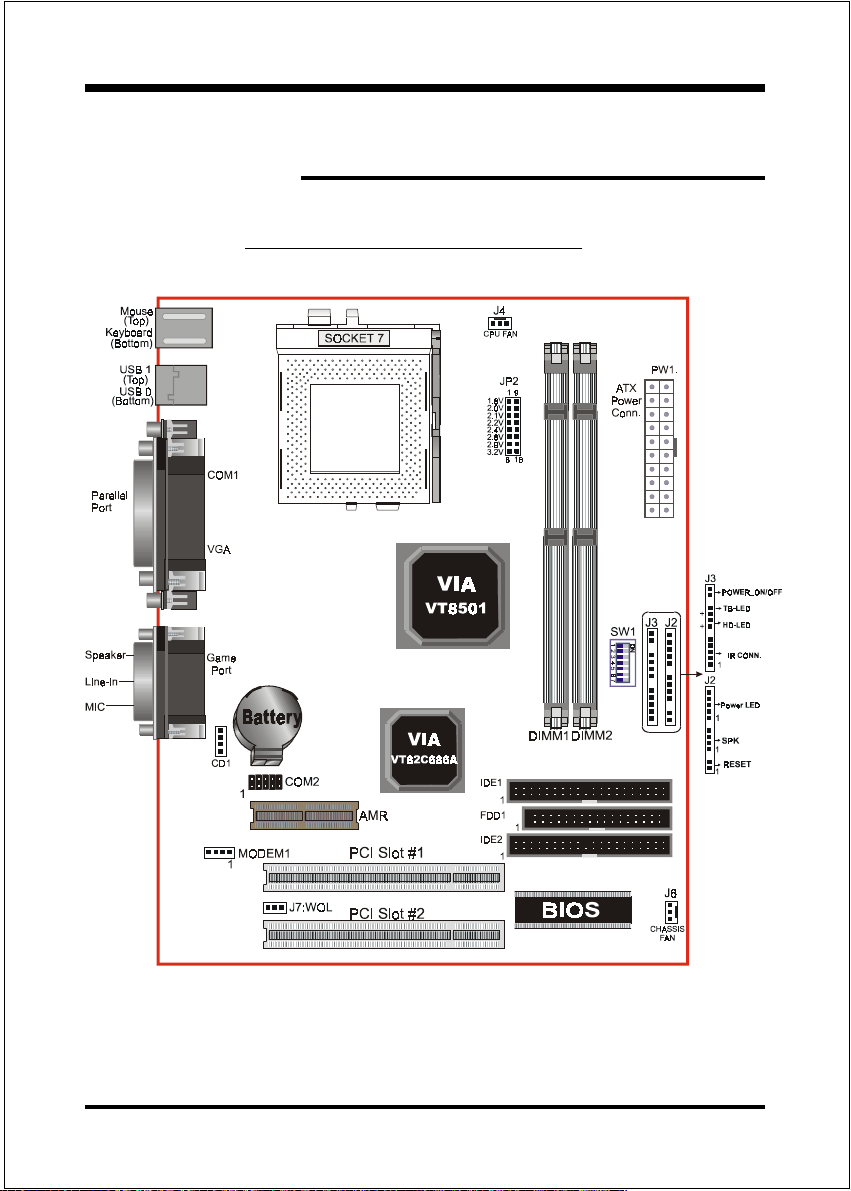
Mainboard Detailed Layout ................................. 3-2
Easy Installation Procedure
CPU Insertion ......................................................3-3
Jumper Settings ................................................... 3-5
System Memory Configuration .......................... 3-7
Device Connectors .............................................. 3-9
T able of Contents
Page
Section 4 Award BIOS Setup
BIOS Instructions ................................................ 4-1
Standard CMOS Setup .........................................4-2
BIOS Features Setup ........................................... 4-3
Chipset Features Setup ........................................ 4-8
Power Management Setup ................................... 4-11
PNP/PCI Configuration ...................................... 4-14
Integrated Peripherals ......................................... 4-17
Load Setup Defaults ............................................ 4-20
Sensor and CPU Speed Setup .............................. 4-21
Change Supervisor or User Password................. 4-23
Page 4

Appendix
IDE HDD Auto Detection..................................... 4-24
Save & Exit Setup ................................................ 4-26
Exit Without Saving............................................. 4-26
Appendix A
GHOST 5.1/6.03 Quick Users Guide ................A-1
Appendix B
Update Your System BIOS .................................. B-1
Page 5
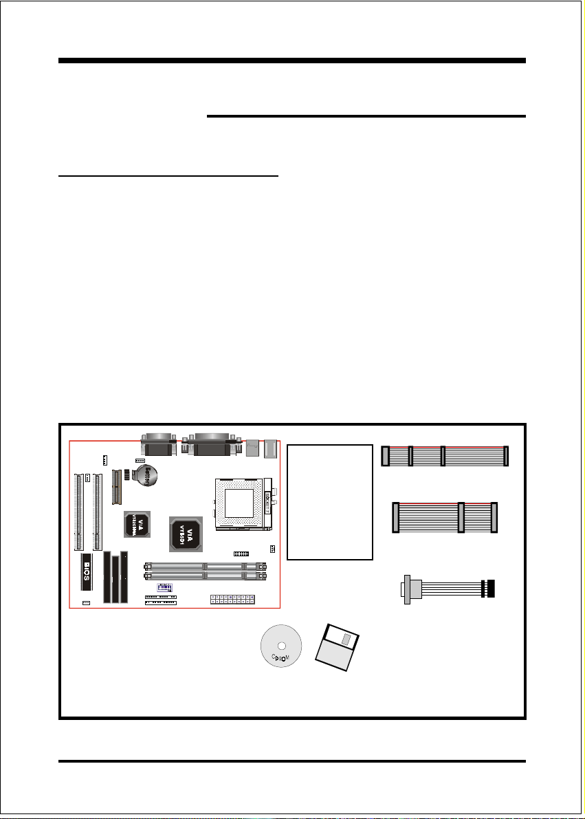
Components Checklist
99
9 A. (1) One mainboard
99
99
9 B. (1) One users manual
99
99
9 C. (1) Floppy ribbon cable
99
99
9 D. (1) ATA-66 IDE ribbon cable
99
99
9 E. (1) COM Port Connector
99
99
9 F. (1) Driver and utility
99
Introduction
Section 1
INTRODUCTION
USERS
MANUAL
B
A
or
F
C
D
E
Page 1-1
Page 6
Introduction
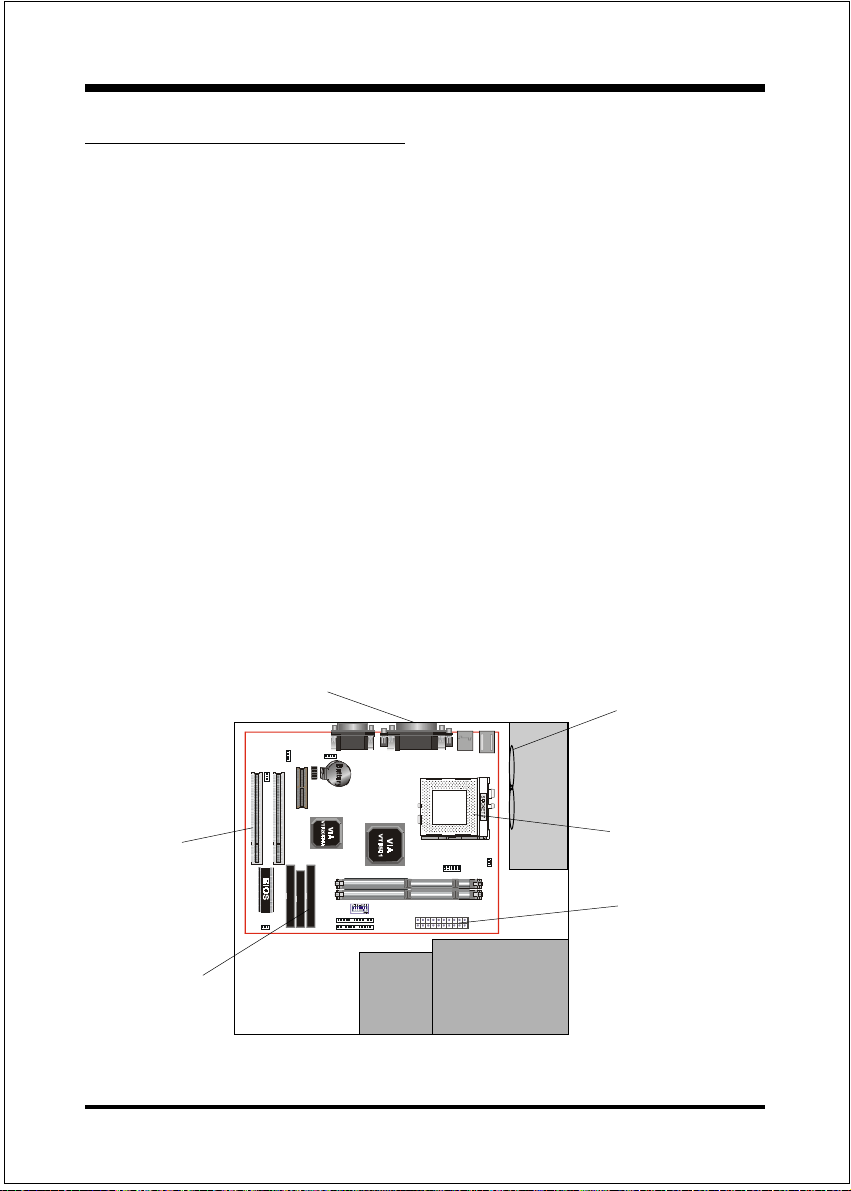
Mainboard Form Factor
The board is designed with MicroATX form factor - the new industry standard of
chassis. The MicroATX form factor is essentially a Baby-AT baseboard rotated 90
degrees within the chassis enclosure and a new mounting configuration for the
power supply. With these changes the processor is relocated away from the
expansion slots, allowing them all to hold full length add-in cards. MicroATX
defines a double height aperture to the rear of the chassis which can be used to
host a wide range of onboard I/O. Only the size and position of this aperture is
defined, allowing PC manufacturers to add new I/O features (e.g.; TV input, TV
output, joystick, modem, LAN, etc.) to systems. This will help systems integrators differentiate their products in the marketplace, and better meet your needs.
Smaller size promotes a smaller system size.
I/O shield does not need to be retooled in an ATX 2.01 or later. Mainboard
could be used in an ATX 2.01-compliant.
A smaller power supply cam be used. High integration on mainboard reduces
the system costs.
PCI slots
Floppy / IDE
connectors
Page 1-2
Expandable I/O
Micro
ATX
Power
Supply
3 1/2"
Bay
Figure 2: Summary of Micro ATX chassis features
5 1/4"
Bay
Single chassis
fan for
system
CPU located near
Power Supply
ATX power
connector
Page 7
Introduction
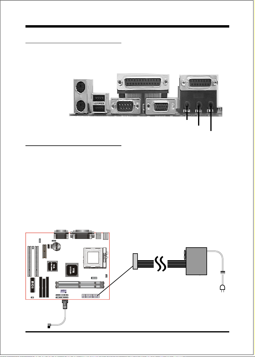
I/O Shield Connector
The board is equipped with an I/O back panel.Please use the appropriate I/O shield
(figure 3).
parallel port
Joystick/Midi
PS/2 Mouse
PS/2
KEYBOARD
USB port
COM1 VGA1
Figure 3
Speaker
Line_in
MIC
Power-On/Off (Remote)
The board has a single 20-pin connector for ATX power supplies. For ATX power
supplies that support the Remote On/Off feature, this should be connected to the
systems front panel for system Power On/Off button. The systems power On/Off
button should be a momentary button that is normally open.
The board has been designed with Soft Off" functions. You can turn Off the
system from one of two sources: The first is the front panel Power On/Off
button, and the other is the "Soft Off" function (coming from the onboard circuit
controller) that can be controlled by the operating system such asWindows® 95/
98/SE/ME or Windows®2000.
J3
Case (chassis) Power
ON/OFF button
ATX
POWER SUPPLY
Figure 4: Simple ATX Power
ON/OFF Controller
Page 1-3
Page 8
Introduction
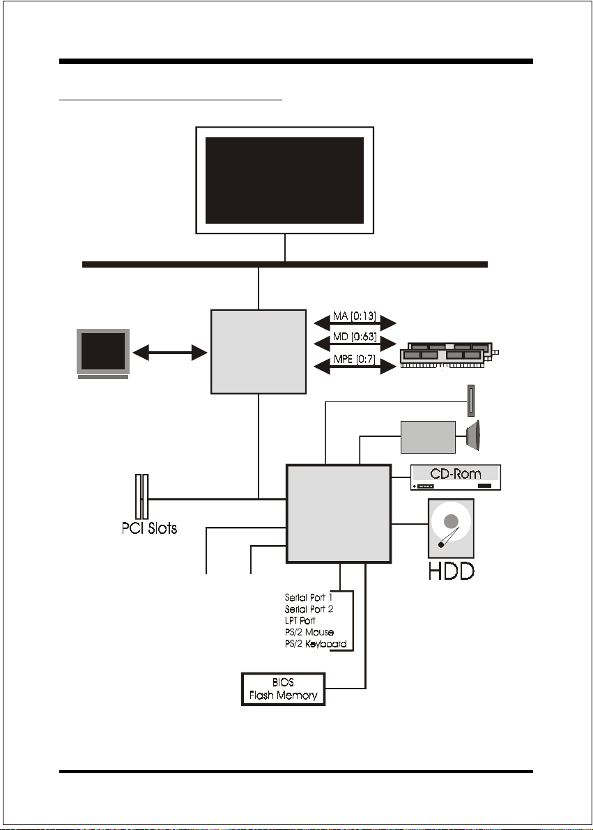
System Block Diagram
socket 7
Processor
100/66 MHz
CRT
PAC
PCI Bridge
and memory
controller
VT8501
USB 0 USB 1
VT82C686A
I/O Bridge
100/66 MHz
AC97
CODEC
AMR Slot
~
~
~
Page 1-4
Figure 5: System Block Diagram
Page 9

Mainboard Features:
PROCESSOR
- Socket 7 CPUs: Operating at 166-550MHz
- AMD K6-2/III, Cyrix M II, Idt C6 / Winchip2 and Rise mP6 series
- Intel Pentium ®/Pentium ® Processor with MMX
CHIPSET
- VIA Apollo MVP4 AGPset (VT8501 + VT82C686A)
DRAM MODULE
- 168pin DIMM x 2 for PC100 Memory
- DRAM Size: 32MB to 256MB
TM
.A=JKHAI
Section 2
FEATURES
Technology,
EXPANSION SLOT
- PCI x 2
- AMR Slot x 1
ONBOARD I/O
- On-Chip Multi I/O integrated with K/B, mouse, FDD, Parallel and Serial,
Fast IR and Power-ON controllers
ONBOARD PCI / IDE
- PCI Bus IDE Port with PIO /Ultra DMA-66x 2 (Up to 4 Devices)
I/O CONNECTOR
- PS/2 Mouse and PS/2 style Keyboard
Page 2-1
Page 10

.A=JKHAI
USB
- USB connector x 4 (2 for Opt.)
BIOS
- Award Plug & Play BIOS
Built-in AC97 Digital Audio (by VT82C686A)
- Dual full-duplex Direct Sound channels
- H/W Sound Blaster Pro for DOS legacy compatibility
- FM synthesis for legacy compatibility
- Supports game and MIDI port
Built-in Trident AGP Core
EXTENDED FUNCTION
- Supports exclusive USDM(Unified System Diagnostic Manager) and
Hardware Monitoring Function by VT82C686A
- Supports exclusive KBPO(KeyBoard Power On)
- Supports CPU Clock setting via DIP Switch
- Supports Wake-On-LAN Function
FORM FACTOR
- 235mm x 180mm Micro ATX Size
Page 2-2
Page 11
INSTALLATION
Mainboard Detailed Layout
Installation
Section 3
Figure 1
Page 3-1
Page 12
Installation
Easy Installation Procedure
The following must be completed before powering on your new system:
3-1. CPU Insertion
3-2. Jumper Settings
3-3. System memory Configuration
3-4. Device Connectors
Section 3-1
CPU Insertion
CPU Insertion
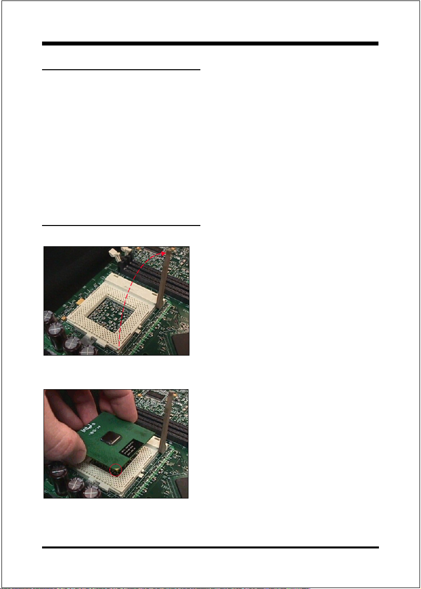
Step 1
Open the socket by raising the actuation
lever.
Page 3-2
Figure 2
Figure 3
Step 2
Insert the processor.
Ensure proper pin 1 orientation by aligning
the FC-PGA corner marking with the
socket corner closest to the actuation arm
tip. The pin field is keyed to prevent misoriented insertion.
Dont force processor into socket. If it does
not go in easily, check for mis-orientation and
debris. Make sure the processor is fully inserted into the socket on all sides.
Page 13
Installation
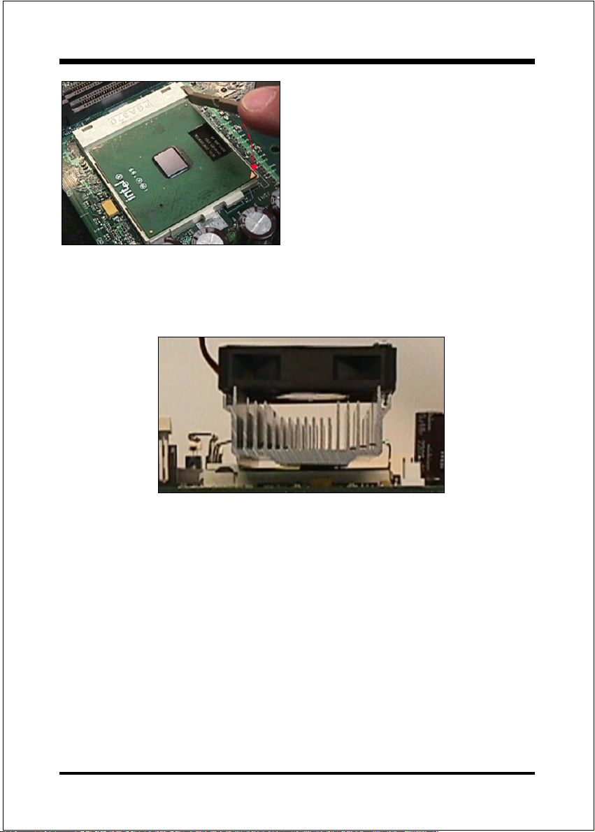
Step 3
Close the socket by lowering and
locking the actuation lever.
Figure 4
Note: Intels reference design thermal solution is an active heatsink; an extruded alumi-
num heatsink based and a fan attached to the top on the fin array. (See Figure 5)
Figure 5
Page 3-3
Page 14
Installation
Section 3-2
Jumper Settings
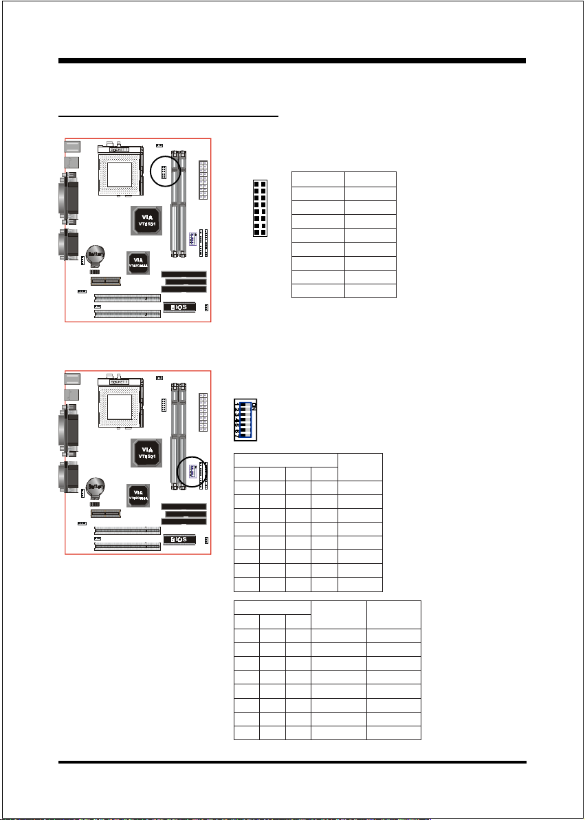
JP2: CPU Vcore Voltage Selection
1.8V
2.0V
2.1V
2.2V
2.4V
2.8V
2.9V
3.2V
189
16
2PJerocVUPC
9-1V8.1
01-2V0.2
11-3V1.2
21-4V2.2
31-5V4.2
41-6V8.2
51-7V9.2
61-8V2.3
SW1: CPU Speed Selection
1WS
123 4
NOzHM66
NONOzHM38
NONOzHM09
NONOzHM59
NONONOzHM001
NONONOzHM501
NONONOzHM511
1WS
567
NOX2
NONOX5.2
NOX3
NONOX4
NONONOX5.4
NONOX533.2
NOX5.566.2
NOzHM57
UPC
X5.3
suB
kcolC
reilpitluM
6CTDI/xiryC/DMA
UPC
reilpitluM
2pihCniWTDI
Page 3-4
Page 15

Installation
+276OFA 59
Pentium/MMX
AMD K6/K6-2/K6III
IDT-C6
166MHz PR200 ON ON ON 66MHz
250MHz PR366 300MHz *PR366 ON ON ON ON ON 100MHz
200MHz PR266 200MHz ON ON 66MHz
250MHz PR333 266Mhz ON O N ON 83MHz
300MHz *PR433 *PR400 ON ON ON ON 100MHz
233MHz PR300 233MHz ON 66MHz
333MHz *PR466 *PR433 ON ON 95MHz
350MHz *PR500 *PR466 ON ON ON 100MHz
266MHz *PR333 266MHz ON ON ON 66MHz
333MHz *PR466 ON ON ON ON 83MHz
380MHz *PR533 ON ON ON ON 95MHz
400MHz *PR550 ON ON ON ON ON 100MHz
300MHz ON ON ON ON 66MHz
450MHz ON ON ON ON ON ON 100MHz
333MHz ON ON ON 66MHz
*500MHz 266MHz ON ON ON ON O N 100MHz
366MHz ON ON 66MHz
*550MHz 300MHz ON ON ON ON 100MHz
Cyrix /IBM
6x86MX/MII
PR233 ON ON ON 75MHz
PR266 233MHz ON ON ON ON 83M Hz
PR300 *PR333 ON ON ON ON 95MHz
PR300 225MHz ON O N 75MHz
PR400 *PR380 ON ON ON 95MHz
PR333 ON 75MHz
*PR400 ON ON 83MHz
*PR400 ON ON ON 75MHz
IDT Winchip 2 Rise MP6
1234567
CPU
Bus
Clock
CPU
Multiplier
2.5X
3X
3.5X
4X
4.5X
5X475MHz ON ON ON ON 95MHz
5.5X
Page 3-5
Page 16

Installation
Section 3-3
System Memory Configuration
Memory Layout
The board supports (2) PC100 168-pin DIMMs (Dual In-line Memory Module).
The DIMMs is for SDRAM (Synchronous DRAM) .
DIMM SDRAM may be 83MHz (12ns), 100MHz (10ns),
125MHz (8ns) bus speed.
If you use both 50ns and 60ns memory you must configure
your BIOS to read 60ns.
When using Synchronous DRAM we recommend using the
4 clock variety over the 2 clock.
Figure 6 and Table 1 show several possible memory configuration.
DIMM 1
DIMM 2
Bank 0/1
Bank 2/3
-Synchronous
DRAM
Figure 6
yromeMlatoT
BM652=
mumixaM
BM215=
mumixaM
1MMID
)1/0knaB(
*MARDS
1XBM652
*MARDS
1XBM652
,BM821,BM46,BM23
,BM821,BM46,BM23
enoN
2MMID
)3/2knaB(
*MARDS
,BM821,BM46,BM23
1XBM652
Table 1
* SDRAM supports 32, 64, 128, 256MB DIMM modules.
* We recommend to use PC100 Memory Module for bus speed between
66MHz and 100MHz.
* Using non-compliant memory with higher bus speed (over clocking) may
severely compromise the integrity of the system.
Page 3-6
Page 17
Installation
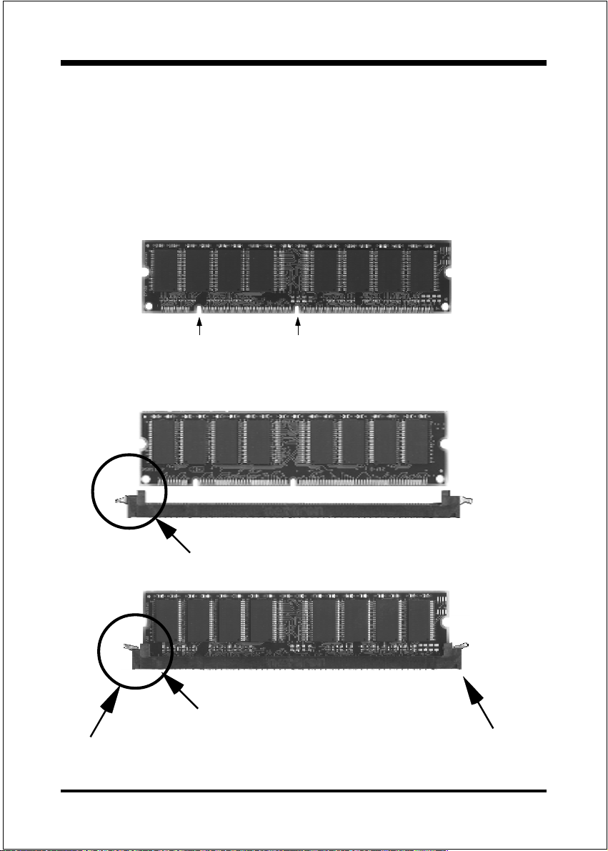
DIMM Module Installation
Figure 7 displays the notch marks and what they should look like on your DIMM
memory module.
DIMMs have 168-pins and two notches that will match with the onboard DIMM
socket. DIMM modules are installed by placing the chip firmly into the socket at a
90 degree angle and pressing straight down (figure 8) until it fits tightly into the
DIMM socket (figure 9).
LEFT KEY ZONE
(UNBUFFERED)
DIMM Module clip before installation
DIMM Module clip after installation
To remove the DIMM module simply press down both of the white clips on
either side and the module will be released from the socket.
CENTER KEY ZONE
(3.3 V DRAM)
Figure 7
Figure 8
Figure 9
Page 3-7
Page 18
Installation
Section 3-4
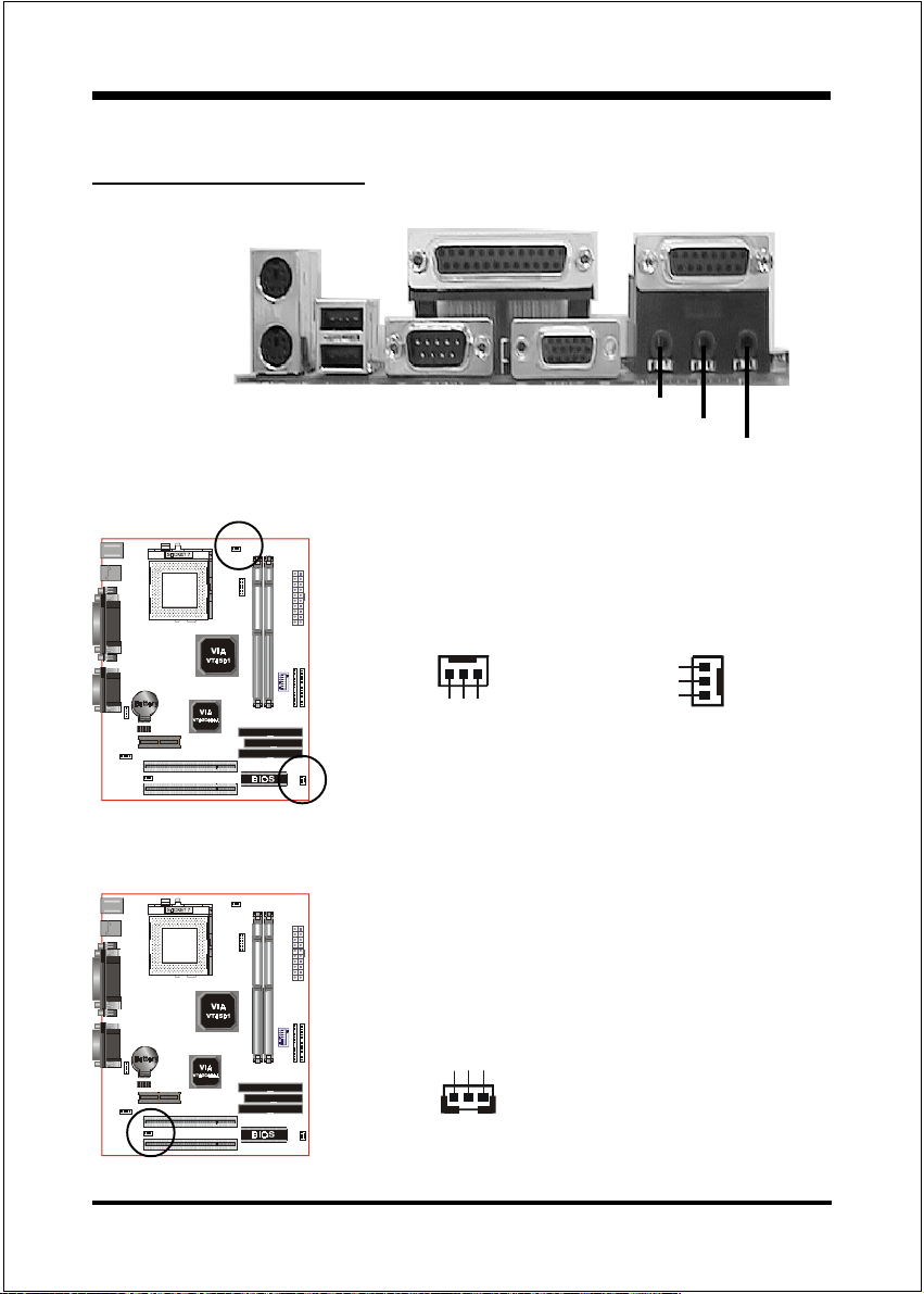
Device Connectors
parallel port
Joystick/Midi
PS/2 Mouse
PS/2
KEYBOARD
USB port
COM1 VGA1
Speaker
Line_in
MIC
J4
J4/J6: CPU/Chassis Fan
A plug-in for the CPU/Chassis Fan Power
CPU Fan
GND
J6
+12V
Rotation
Chassis Fan
GND
+12V
Rotation
Page 3-8
J7: WOL (Wake On LAN) Connector
Reserved for NIC (Network Interface Card) to
wake the system.
+5V Standby
GND
PME
Page 19
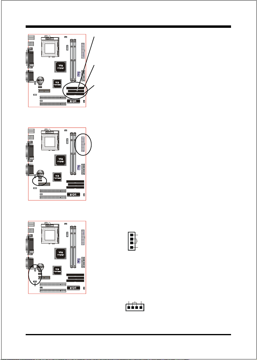
COM2
FDD1: Floppy Controller Connector (Black color)
IDE1: Ultra ATA-66 Primary IDE Connector
(White color)
IDE2: Ultra ATA-66 Secondary IDE Connector
(White color)
PW1
PW1: ATX Power Connector
20-pin power connector
COM2: RS232 COM2 Connector
Installation
CD1
MODEM1
CD1: CD Audio_IN Connector
CD_IN_Right
CD_Reference
CD_IN_Left
1
MODEM1: Telephony Connector for Modem audio
output
CD_IN_Left
CD_IN_Right
GND
1
Page 3-9
Page 20
Installation
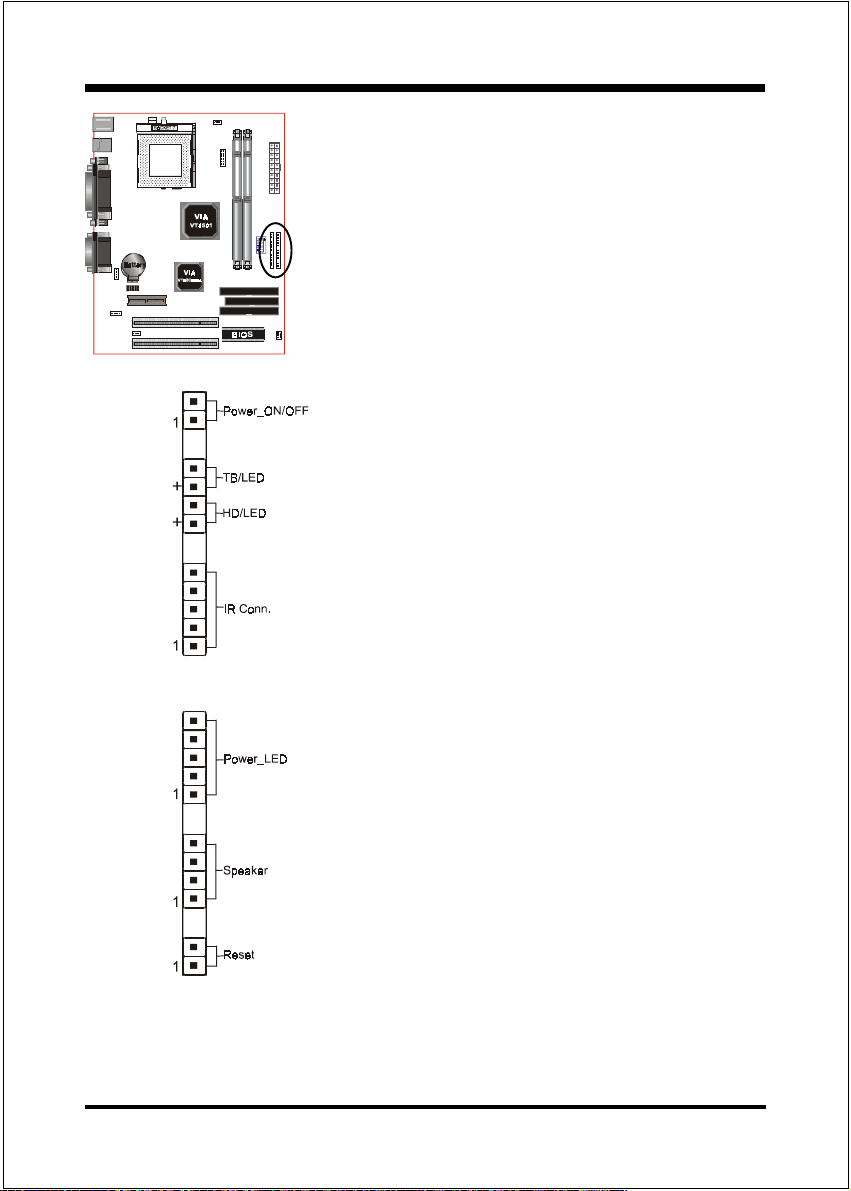
J3
Power On/Off
(This is connected to the power button on the
case. Using the Soft-Off by Pwr-BTTN feature,
you can choose either Instant Off (turns
system off immediately), or 4 sec delay (you
need to push the button down for 4 seconds
before the system turns off). When the system
is in 4 sec delay mode, suspend mode is
enabled by pushing the button momentarily.)
Turbo LED indicator
LED ON when higher speed is selected
IDE LED indicator
LED ON when Onboard PCI IDE Hard disks is
activate
IR Connector
1. VCC 4. GND
2. NC 5. IRTX
3. IRRX
J2
Page 3-10
Power LED
Power LED connector
1. Power LED(+) 4. NC
2. N/C 5. GND
3. GND
Speaker
Connect to the system's speaker for beeping
1. Speaker 3. GND
2. N/C 4. GND
Reset
Closed to restart system.
Page 21

Installation
Page Left Blank
Page 3-11
Page 22

BIOS
Section 4
AWARD BIOS SETUP
BIOS Instructions
Awards ROM BIOS provides a built-in Setup program which allows user to
modify the basic system configuration and hardware parameters. The modified
data will be stored in a battery-backed CMOS, so that data will be retained even
when the power is turned off. In general, the information saved in the CMOS RAM
will stay unchanged unless there is a configuration change in the system, such as
hard drive replacement or a device is added.
It is possible for the CMOS battery to fail, this will cause data loss in the CMOS
only. If this does happen you will need to reconfigure your BIOS settings.
To enter the Setup Program :
Power on the computer and press the <Del> key immediately, this will bring you
into the BIOS CMOS SETUP UTILITY.
Figure 1: CMOS Setup Utility
Page 4-1
Page 23

BIOS
The menu displays all the major selection items. Select the item you need to
reconfigure. The selection is made by moving the cursor (press any direction key )
to the item and pressing the Enter key. An on-line help message is displayed at
the bottom of the screen as the cursor is moved to various items which provides a
better understanding of each function. When a selection is made, the menu of the
selected item will appear so that the user can modify associated configuration
parameters.
4-1 Standard CMOS Setup
Choose Standard CMOS Setup in the CMOS SETUP UTILITY Menu (Figure 2).
The Standard CMOS Setup allows the user to configure system settings such as
the current date and time, type of hard disk drive installed, floppy drive type, and
display type. Memory size is auto-detected by the BIOS and displayed for your
reference. When a field is highlighted (use direction keys to move the cursor and
the <Enter> key to select), the entries in the field can be changed by pressing the
<PgDn> or the <PgUp> key.
Page 4-2
Figure 2: Standard CMOS Setup
Page 24

BIOS
Note: If the hard disk Primary Master/Slave and Secondary Master/Slave
are set to Auto, then the hard disk size and model will be autodetected.
Note: The Halt On: field is used to determine when to halt the system by
the BIOS if an error occurs.
Note: Floppy 3 Mode support is a mode used to support a special 3.5 drive
used in Japan. This is a 3.5 disk that stores only 1.2 MB, the
default setting for this is disabled.
4-2 BIOS Fea tures Setup
Selecting the BIOS FEATURES SETUP option in the CMOS SETUP UTILITY
menu allows users to change system related parameters in the displayed menu.
This menu shows all of the manufacturers default values for the EP-MVP4F.
Pressing the [F1] key will display a help message for the selected item.
Figure 3: BIOS Features Setup
Page 4-3
Page 25

BIOS
Virus Warning: During and after the system boots up, any attempt to write to the
boot sector or partition table of the hard disk drive will halt the system and an
error message will appear.
You should then run an anti-virus program to locate the virus. Keep in mind that
this feature protects only the boot sector, not the entire hard drive.
The default value is Disabled.
Enabled: Activates automatically when the system boots up causing a warning
message to appear when anything attempts to access the boot sector.
Disabled: No warning message will appear when anything attempts to access the
boot sector.
Note: Many disk diagnostic programs that access the boot sector table can
trigger the virus warning message. If you plan to run such a program, we
recommend that you first disable the virus warning.
CPU Internal Cache: This controls the status of the processors internal cache
area. The default is Enabled.
Enabled: This activates the processors internal cache thereby increasing
performance.
Disabled: This deactivates the processors internal cache thereby lowering
performance.
Quick Power On Self Test: This category speeds up the Power On Self Test
(POST). The default is Enabled.
Enabled: This setting will shorten or skip of the items checked during POST.
Disabled: Normal POST.
Boot Sequence: This category determines which drive is searched first by the O/S
(Operating System). The default is A,C,SCSI.
The following is your list of options:
[A, C, SCSI] - [C, A, SCSI] - [C, CD-ROM, A] - [CD-ROM, C, A],[D, A,CD-ROM],
[E, A, CD-ROM] - [F, A, CD-ROM] - [SCSI, A, C], [SCSI C, A] - [C Only]
Swap Floppy Drive: This will swap your physical drive letters A & B if you are
using two floppy disks. The default is Disabled.
Enabled: Floppy A & B will be swapped under the O/S.
Disabled: Floppy A & B will be not swapped.
Page 4-4
Page 26

BIOS
Boot Up Floppy Seek: During Power-On-Self-Test (POST), BIOS will determine if the floppy disk drive installed is 40 or 80 tracks. Only 360K type is 40
tracks while 760K, 1.2MB and 1.44MB are all 80 tracks. The default is Enabled.
Enabled: The BIOS will search the floppy disk drive to determine if it is 40 or
80 tracks.
Disabled: The BIOS will not search for the type of floppy disk drive by track
number.
Note: BIOS can not tell the difference between 720K, 1.2MB and 1.44MB
drive types as they are all 80 tracks.
Boot Up NumLock Status: This controls the state of the NumLock key when the
system boots. The default is On.
On: The keypad acts as a 10-key pad.
Off: The keypad acts like the cursor keys.
Gate A20 Option: This refers to the way the system addresses memory above
1MB (extended memory). The default is Fast.
Normal: The A20 signal is controlled by the keyboard controller or chipset
hardware.
Fast: The A20 signal is controlled by Port 92 or chipset specific method.
Typematic Rate Setting: This determines the keystrokes repeat rate.
The default is Disabled.
Enabled: Allows typematic rate and typematic delay programming.
Disabled: The typematic rate and typematic delay will be controlled by the
keyboard controller in your system.
Typematic Rate (Chars/Sec): This is the number of characters that will be
repeated by a keyboard press. The default is 6.
6: 6 characters per second. 8: 8 characters per second.
10: 10 characters per second. 12: 12 characters per second.
15: 15 characters per second. 20: 20 characters per second.
24: 24 characters per second. 30: 30 characters per second.
Typematic Delay (msec): This setting controls the time between the first and the
second character displayed by typematic auto-repeat. The default is 250.
Page 4-5
Page 27

BIOS
250: 250 msec. 500: 500 msec.
750: 750 msec. 1000: 1000 msec.
Security Option: This category allows you to limit access to the System and
Setup, or just to Setup. The default is Setup.
System: The system will not boot and the access to Setup will be denied if the
correct password is not entered at the prompt.
Setup: The system will boot; but the access to Setup will be denied if the
incorrect password is not entered at the prompt.
PCI/VGA Palette Snoop: This field controls the ability of a primary PCI VGA
controller to share a common palette (When a snoop write cycles) with an ISA
video card. The default is Disabled.
Enabled: If an ISA card is connected to a PCI VGA card via the VESA connector,
and that ISA card connects to a VGA monitor, then that ISA card uses
the RAMDAC of the PCI card.
Disabled: Disables the VGA card Palette Snoop function.
OS Select For DRAM > 64MB: Some operating systems require special
handling. Use this option only if your system has greater than 64MB of memory.
The default is Non-OS2.
OS2: Select this if you are running the OS/2 operating system with greater
than 64MB of RAM.
Non-OS2:Select this for all other operating systems and configurations.
Report No FDD For WIN 95: Whether report no FDD for Win 95 or not.
Video BIOS Shadow: This option allows video BIOS to be copied into RAM.
Video Shadowing will increase the video performance of your system.
The default is Enabled.
Enabled: Video shadow is enabled.
Disabled: Video shadow is disabled.
C8000 - CBFFF Shadow:
CC000 - CFFFF Shadow:
D0000 - D3FFF Shadow:
Page 4-6
Page 28

BIOS
D4000 - D7FFF Shadow:
D8000 - DBFFF Shadow:
DC000 - DFFFF Shadow:
These categories determine whether ROMs from option cards will be copied into
RAM. This will be in 16K byte or 32K byte units, and the size will depend on
chipset of the option card.
Enabled: Optional shadow is enabled.
Disabled: Optional shadow is disabled.
Page 4-7
Page 29

BIOS
4-3 Chipset Fea tures Setup
Choose the CHIPSET FEATURES SETUP in the CMOS SETUP UTILITY menu
to display following menu.
Figure 4: Chipset Features Setup
Bank 0/1, 2/3, 4/5 DRAM Timing: This value in this field is set by the system
board manufacturer, depending on whether the board has paged DRAMs.
The Choice: Bank 0/1, 2/3, 4/5.
SDRAM Cycle length: This setting defines the CAS timing parameter of the
SDRAM in terms of clocks. The default is 3.
2: Provides faster memory performance.
3: Provides better memory compatibility.
DRAM Page-Mode: This item will active or inactive chipset page registers.
Enabled: Page-Mode Enabled.
Disabled: No page registers update and non Page-Mode operation.
Page 4-8
Page 30

BIOS
DRAM Fast Decoding: This item will effective DRAM operation sequential.
The Choice: Enabled, Disabled.
DRAM Read Pipeline: You may select Enabled fo this field when PBSRAMs
are installed. Pipelining improves system performance.
The Choice: Enabled, Disabled.
Sustained 3T Write: This item allow you to enable or disable direct map write
back / write through secondary cache.
The Choice: Enabled, Disabled.
Cache R/CPU W Pipeline: This item allows you to enable/disabled the cache
timing.
The Choice: Enabled, Disabled.
Video BIOS Cacheable: When enabled. The Video BIOS cache will cause access
to video BIOS addressed at C0000H to C7FFFH to be cached, if the cache
controller is also enabled
The Choice: Enabled, Disabled.
System BIOS Cacheable: As with caching the Video BIOS above, enabling this
selection allows accesses to the system BIOS ROM addressed at F0000HFFFFFH to be cached, provided that the cache controller is enabled.
The Choice: Enabled, Disabled.
Memory Hole: You can reserve this memory area for the use of ISA adaptor
ROMs. The default is Disabled.
Enabled: This field enables the main memory (15~16MB) to remap to ISA BUS.
Disabled: Normal Setting.
Note: If this feature is enabled you will not be able to cache this memory
segment.
Init Display First: If two video cards are used (1 AGP and 1 PCI) this specifies
which one will be the primary display adapter.
The default is PCI Slot.
PCI Slots: PCI video card will be primary adapter.
AGP: AGP video card will be primary adapter.
Page 4-9
Page 31

BIOS
Frame Buffer Size: Specify the size of system memory to allocate for video
memory, from 1 MB to 8 MB.
The Choice: 2MB, 4MB, 8MB.
AGP Aperture Size: The amount of system memory that the AGP card is allowed
to share. The default is 64.
4: 4MB of systems memory accessable by the AGP card.
8: 8MB of systems memory accessable by the AGP card.
16: 16MB of systems memory accessable by the AGP card.
32: 32MB of systems memory accessable by the AGP card.
64: 64MB of systems memory accessable by the AGP card.
128: 128MB of systems memory accessable by the AGP card.
256: 256MB of systems memory accessable by the AGP card.
OnChip USB: Select Enabled if your system contains a Universal Serial Bus
(USB) controller and you have a USB peripheral.
USB Keyboard Support: This controls the activation status of an optional USB
keyboard that may be attached. The default is disabled.
Enabled: Enable USB keyboard support.
Disabled: Disable USB keyboard support.
OnChip AGP: This item allows you to enable/disable AGP function.
OnChip Sound: Turn on/off onchip sound device.
OnChip Modem: Turn on/off onchip software modem device.
Page 4-10
Page 32

BIOS
4-4 Power Management Setup
Choose the POWER MANAGEMENT SETUP in the CMOS SETUP UTILITY to
display the following screen. This menu allows the user to modify the power
management parameters and IRQ signals. In general, these parameters should not
be changed unless its absolutely necessary.
Figure 5: Power Management Setup
ACPI Function: This option allows you to select ACPI Function.
The default is Enabled.
Enabled: Support ACPI function for new O.S
Disabled: No Support ACPI function.You can only change the content of Doze
Mode, Standby Mode, and Suspend Mode when the Power Management
is set to User Define.
Power Management: Use this to select your Power Management selection.
The default is User define.
Disabled: The system operates in NORMAL conditions (Non-GREEN), and
the Power Management function is disabled.
Max. saving: Maximum power savings. Inactivity period is 1 minute in each
mode.
Page 4-11
Page 33

BIOS
Min. saving: Minimum power savings. Inactivity period is 1 hour in each mode.
User define: Allows user to define PM Timers parameters to control power
saving mode.
PM controlled APM: This option shows weather or not you want the Power Management to be controlled the Advanced Power Management (APM).
The default is Yes.
Ye s: APM controls your PM
No: APM does not control your PM
Video Off After: Tells you what time frame that the video will be disabled under
current power management settings.
Doze: Video powers off after time shown in doze mode timing.
Suspend: Video powers off after time shown in suspend mode timing.
N/A: Video power off not controlled by power management.
Video Off Method: This option allows you to select how the video will be
disabled by the power management. The default is V/H Sync + Blank
V/H Sync + Blank: System turns off vertical and horizontal synchronization ports
and writes blanks to the video buffer.
DPMS: Select this option if your monitor supports the Display Power
Management Signaling (DPMS) standard of the Video
Electronics Standards Association (VESA). Use the software
supplied for your video subsystem to select video power
management values.
Blank Screen: System only writes blanks to the video buffer.
MODEM Use IRQ: Name the interrupt request (IRQ) line assigned to the
modem (if any) on your system. Activity of the selected IRQ always awakens the
system. Default is IRQ 3.
N/A: No IRQ is used. 3: IRQ 3
4: IRQ 4 5: IRQ 5
7: IRQ 7 9: IRQ 9
10: IRQ 10 11: IRQ 11
Page 4-12
Page 34

BIOS
Doze Mode: The Doze mode timer starts to count when no PM events have
occurred.
Suspend Mode: This function works only when the Pentium II Processor is
installed. The timer starts to count when System Standby mode timer is timed
out and no PM Events are occurring. Valid range is from 1 minute up to 1 hour.
HDD Power Down: HDD Standby timer can be set from 1 to 15 minute(s).
Soft-Off by PWRBTN: Use this to select your soft-off function.
The default is Delay 4 sec.
Instant Off: Turns off instantly.
Delay 4 Second: Turns off after a 4 second delay. If momentary press of button,
the system will go into Suspend Mode. Press again to take
system out of Suspend Mode.
PWRON After PW-Fail: The system will stay of or power on after a power
interrupte. The default is OFF.
Fomer-Status: Stay off or power on depend on system safe shut-down or power
fail.
ON: System always power on after a power interrupte.
OFF: System always stay off after a power interrupte.
VGA: When set to On (default), any event occurring at a VGA port will awaken a
system which has been powered down.
LPT & COM: When set to On (default), any event occurring at a COM(serial)/
LPT (printer) port will awaken a system which has been powered down.
HDD & FDD: When set to On (default), any event occurring at a hard or floppy
drive port will awaken a system which has been powered down.
DMA/master: When set to On (default), any event occurring to the DMA control-
ler will awaken a system which has been powered down.
RTC Alarm Resume: When set to Enable rta alarm resume, you could set the
date (of month) and timer (hh:mm:ss), any event occurring at will awaken a system
which has been powered down.
Page 4-13
Page 35

BIOS
Modem Ring Resume: When set to Enabled, any event occurring to the Modem
Ring will awaken a system which has been powered down.
Primary INTR: When set to On (default), any event occurring at will awaken a
system which has been powered down.
4-5 PNP/PCI Configuration
The PNP/PCI configuration program is for the user to modify the PCI/ISA IRQ
signals when various PCI/ISA cards are inserted in the PCI or ISA slots.
WARNING: Conflicting IRQs may cause the system to not find certain devices.
Figure 6: PCI Configuration Setup
PNP OS Installed: Do you have a PNP OS installed on your system. The default
is No.
Resources Controlled By: Who controlled the system PNP/PCI resources.
The default is Auto.
Manual: PNP Cards resources will be controlled manually. You can set which
IRQ-X and DMA-X are assigned to PCI/ISA PNP or Legacy ISA Cards.
Page 4-14
Page 36

BIOS
Auto: If your ISA card and PCI card are all PNP cards, BIOS will assign the
interrupt resource automatically.
Reset Configuration Data: This setting allows you to clear ESCD data.
The default is Disabled
Disabled: Normal Setting.
Enabled: If you have plugged in some Legacy cards to the system and they were
recorded into ESCD (Extended System Configuration Data), you can
set this field to Enabled in order to clear ESCD.
CPU to PCI Write Buffer: When enabled, up to four D words of data can be
written to the PCI bus without interruting the CPU. When disabled, a write buffer
is not used and the CPU read cycle will not be completed until the PCI bus signals
that it is ready to receive the data.
The Choice: Enabled, Disabled.
PCI Dynamic Bursting: When Enabled, data transfers on the PCI bus, where
possible, make use of the high-performance PCI bust protocol, in which graeater
amounts of data are transferred at a single command.
The Choice: Enabled, Disabled.
PCI Master 0 WS Write: When Enabled, writes to the PCI bus are command
with zero wait states.
The Choice: Enabled, Disabled.
PCI Delay Transaction: The chipset has an embedded 32-bit posted write buffer
to support delay transactions cycles. Select Enabled to support compliance with
PCI specification version 2.1.
The Choice: Enabled, Disabled.
PCI #2 Access #1 Retry: This item allows you enabled/disable the PCI #2
Access #1 Retry.
The Choice: Enabled, Disabled.
AGP Master 1 WS Write: When Enabled, writes to the AGP bus are executed
with one wait states.
The Choice: Enabled, Disabled.
Page 4-15
Page 37

BIOS
AGP Master 1 WS Read: When Enabled, read to the AGP bus are executed with
one wait states.
The Choice: Enabled, Disabled.
Assign IRQ For USB/VGA: This item allows BIOS to assign whether IRQ is
with USB/VGA or not. If you have not connect the USB/VGA device. Can release
the IRQ for other device. The default is Enabled.
Enalbed: Provides IRQ for USB/VGA device.
Disabled: Release IRQ for other device.
Slot 1 to Slot 4 Use IRQ No: These settings allow the user to specify what IRQ
will be assigned to PCI devices in the chosen slot. Options available: Auto, 3, 4,
5, 7, 9, 10, 11, 12, 14 & 15.
Page 4-16
Page 38

BIOS
4-6 Integrated Peripherals
Figure 8: Integrated Peripherals
Note: If you do not use the Onboard IDE connector, then you will need to
set Onboard Primary PCI IDE: Disabled and Onboard Secondary
PCI IDE: Disabled
Note: The Onboard PCI IDE cable should be equal to or less than 18
inches (45 cm.).
Onchip IDE Channel0/1: The default value is Enabled.
Enabled: Enables Onboard IDE primary/secondary port.
Disabled: Disables Onboard IDE primary/secondary port.
IDE Prefetch Mode: Enable prefetching for IDE drive interfaces that support its
faster drive accesses. If uou are getting disk drive errors, change the setting to
omit the drive interface where the errors occur. Depending on the configuration
of your IDE subsystem, this field may not appear, and it does not appear when the
Internal PCI/IDE field, above, is Disabled.
The Choice: Enabled, Disabled.
Page 4-17
Page 39

BIOS
IDE HDD Block Mode: IDE Block Mode allows the controller to access blocks
of sectors rather than a single sector at a time. The default is Enabled.
Enabled: Enabled IDE HDD Block Mode. Provides higher HDD transfer rates.
Disabled: Disable IDE HDD Block Mode.
Primary Master/Slave PIO: The default is Auto.
Auto: BIOS will automatically detect the Onboard Primary Master/Slave
PCI IDE HDD Accessing mode.
Mode 0~4: Manually set the IDE Programmed interrupt mode.
Secondary Master/Slave PIO: The default is Auto.
Auto: BIOS will automatically detect the Onboard Secondary Master/Slave
PCI IDE HDD Accessing mode.
Mode 0~4: Manually set the IDE Programmed interrupt mode.
Primary Master/Slave UDMA: This allows you to select the mode of operation
for the hard drive. The default is Auto.
Auto: The computer will select the optimal setting.
Disabled: The hard drive will run in normal mode.
Secondary Master/Slave UDMA: This allows you to select the mode of opera-
tion for the hard drive. The default is Auto.
Auto: The computer will select the optimal setting.
Disabled: The hard drive will run in normal mode.
Onboard FDD Controller: This controls the state of the onboard floppy
controller. The default value is Enabled.
Enabled: Enable the Onboard floppy drive interface controller.
Disabled: Disable the Onboard floppy drive interface controller.
Onboard Serial Port 1/2: This field allows the user to configure the 1st/2nd
serial port. The default is Auto.
AUTO: Enable Onboard Serial port 1/2 and address is Auto adjusted
COM1: Enable Onboard Serial port 1/2 and address is 3F8H/IRQ4.
COM2: Enable Onboard Serial port 1/2 and address is 2F8H/IRQ3.
COM3: Enable Onboard Serial port 1/2 and address is 3E8H/IRQ4.
COM4: Enable Onboard Serial port 1/2 and address is 2E8H/IRQ3.
Disabled: Disable Onboard Serial port 1/2.
Page 4-18
Page 40

BIOS
UART 2 Mode: This item allows you to determine which Infra Red (IR) function
of onboard I/O chip.
The Choice: Standard, ASKIR, HPSIR.
Onboard Parallel port: This field allows the user to configure the LPT port.
The default is 378H / IRQ7.
378H: Enable Onboard LPT port and address is 378H and IRQ7.
278H: Enable Onboard LPT port and address is 278H and IRQ5.
3BCH: Enable Onboard LPT port and address is 3BCH and IRQ7.
Disabled: Disable Onboard LPT port.
Onboard Parallel Mode: This field allows the user to select the parallel port
mode. The default is ECP+EPP.
Normal: Standard mode. IBM PC/AT Compatible bidirectional parallel port.
EPP: Enhanced Parallel Port mode.
ECP: Extended Capabilities Port mode.
EPP+ECP: ECP Mode & EPP Mode.
ECP Mode USE DMA: This field allows the user to select DMA1 or DMA3 for
the ECP mode. The default is DMA3.
DMA1: This field selects the routing of DMA1 for the ECP mode.
DMA3: This field selects the routing of DMA3 for the ECP mode.
Parallel Port EPP Type: This item allows uou to determine the IR transfer mode
of onboard I/O chip.
The Choice: EPP1.9, EPP1.7.
Onboard Legacy Audio: Legacy Audio enabled/disabled.
Sound Blaster: Sound Blaster compatible device enabled/disabled.
SB I/O Base Address: Sound Blaster I/O resource selection.
SB IRQ Select: Legacy audio device IRQ selection.
SB DMA Select: Sound Blaster DMA channel selection.
Page 4-19
Page 41

BIOS
MPU-401: MPU-401 function enabled/disabled.
MPU-401 I/O Address: Built-in MPU-401 compatible MIDI I/O port selection.
The choice: 300-303H, 310-313H, 320-323H, 330-333H (default).
FM Port (388-38BH): Frequency modulation port at I/O port 388-38BH
enabled/disabled.
Game Port (200-207H): Built-in joystick port support disabled/enabled.
4-7 Load Setup Defaults
The LOAD SETUP DEFAULTS function loads the system default data directly
from ROM and initializes the associated hardware properly. This function will be
necessary only when the system CMOS data is corrupted.
Page 4-20
Page 42

4-8 SENSOR AND CPU SPEED SETUP
Figure 9: Sensor And CPU Speed Setup
BIOS
Auto Detect DIMM/PCI Clk: When enabled the motherboard will automatically
disable the clock source for a DIMM socket which does not have a module in it.
Same applies for PCI slots. The default is Enabled.
Spread Spectrum : The default is Disabled.
CPU Host Clock (CPU/PCI): Allows the external clock to be modified depend-
ing upon what FSB has been selected. Should not be used to clock processor faster
than it was designed for. The default is Default.
CPUFAN Off In Suspend: This option is used to set if the CPU fans will turn off
during suspend mode. The default is Enabled.
Enabled: The system will turn off the CPU fans during suspend mode.
Disabled: The system will not turn off the CPU fan during suspend mode.
Current System Temp: This is the Current temperature of the system.
Page 4-21
Page 43

BIOS
Current CPU Temperature: This is the current temperature of the CPU.
Current CPU FAN Speed: The current CPU fan speed in RPMs.
Current Chassis FAN Speed: The current chassis fan speed in RPMs.
CPU(V): The voltage level of the CPU(Vio/Vcore).
+2.5V, +3.3V, +5V, +12V: The voltage level of the switch power supply.
Page 4-22
Page 44

BIOS
4-9 Change Supervisor or User Password
To change the password, choose the SUPERVISOR PASSWORD or USER
PASSWORD option from the CMOS SETUP UTILITY menu and press [Enter].
NOTE: Either Setup or System must be selected in the Security
Option of the BIOS FEATURES SETUP menu.
1. If CMOS is corrupted or the option was not used, a default password
stored in the ROM will be used. The screen will display the following
message:
Enter Password:
Press the [Enter] key to continue after the proper password is given.
2. If the CMOS is corrupted or the option was used earlier and the user
wishes to change the default password, the SETUP UTILITY will display a
message and ask for a confirmation.
Confirm Password:
3. After pressing the [Enter] key (ROM password if the option was not used)
or current password (user-defined password), the user can change the
password and store new one in CMOS RAM. A maximum of 8 characters
can be entered.
Page 4-23
Page 45

BIOS
4-10 IDE HDD Auto Detection
The IDE HDD auto detection utility is a very useful tool, especially when you do
not know which kind of hard disk type you are using. You can use this utility to
detect the correct disk type installed in the system automatically. But now you can
set HARD DISK TYPE to Auto in the STANDARD CMOS SETUP. You dont need
the IDE HDD AUTO DETECTION utility. The BIOS will Auto-detect the hard
disk size and model on display during POST.
ROM PCI/ISA BIOS(2A5LHPAB)
CMOS SETUP UTILITY
AWARD SOFTWARE, INC.
HARD DISKS TYPE SIZE CYLS HEADS PRECOMP LANDZONE SECTORS MODE
Primary Master :
Select Secondary Slave Option (N=Skip) : N
OPTIONS SIZE CYLS HEAD PRECOMP LANDZ SECTORMODE
2 (Y) 4310 524 255 0 14847 63 LBA
1 4310 14848 9 65535 14847 63 NORMAL
3 4310 928 144 65535 14847 63 LARGE
Note: Some OSes (like SCO-UNIX) must use NORMAL for installation
ESC : Skip
Figure 10: IDE HDD Auto Detection
NOTE: HDD Modes
The Award BIOS supports 3 HDD modes : NORMAL, LBA & LARGE NORMAL
mode
Generic access mode in which neither the BIOS nor the IDE controller will make
any transformations during accessing.
The maximum number of cylinders, head & sectors for NORMAL mode are 1024,
16 & 63.
no. Cylinder (1024)
x no. Head ( 16)
x no. Sector ( 63)
x no. per sector ( 512)
528 Megabytes
Page 4-24
Page 46

BIOS
If user set his HDD to NORMAL mode, the maximum accessible HDD size will
be 528 Megabytes even though its physical size may be greater than that!
LBA (Logical Block Addressing) mode: A new HDD accessing method to
overcome the 528 Megabyte bottleneck. The number of cylinders, heads &
sectors shown in setup may not be the number physically contained in the HDD.
During HDD accessing, the IDE controller will transform the logical address
described by sector, head & cylinder into its own physical address inside the
HDD. The maximum HDD size supported by LBA mode is 8.4 GigaBytes which is
obtained by the following formula:
no. Cylinder (1024)
x no. Head ( 255)
x no. Sector ( 63)
x bytes per sector ( 512)
8.4 GigaBytes
LARGE mode: Extended HDD access mode supported by Award Software.
Some IDE HDDs contain more than 1024 cylinder without LBA support (in some
cases, user do not want LBA). The Award BIOS provides another alternative to
support these kinds of LARGE mode.
CYLS HEADS SECTOR MODE
1120 16 59 NORMAL
560 32 59 LARGE
BIOS tricks DOS (or other OS) that the number of cylinders is less than 1024 by
dividing it by 2. At the same time, the number of heads is multiplied by 2. A
reverse transformation process will be made inside
INT 12h in order to access the right HDD address!
Maximum HDD size:
no. Cylinder (1024)
x no. Head ( 32)
x no. Sector ( 63)
x bytes per sector ( 512)
1 GigaByte
Page 4-25
Page 47

BIOS
Note: To support LBA or LARGE mode of HDDs, there must be some
software involved. All the software is located in the Award HDD
Service Routine (INT 13h). It may fail to access a HDD with LBA
(LARGE) mode selected if you are running under an Operating
System which replaces the whole INT 13h.
UNIX operating systems do not support either LBA or LARGE and must utilize
the Standard mode. UNIX can support drives larger than 528MB.
4-11 Save & Exit Setup
The SAVE & EXIT SETUP option will bring you back to the boot up procedure
with all the changes you just recorded in the CMOS RAM.
4-12 Exit Without Saving
The EXIT WITHOUT SAVING option will bring you back to normal boot up
procedure without saving any data into CMOS RAM.
All old data in the CMOS will not be destroyed.
Page 4-26
Page 48

Appendix
Appendix A
A-1 GHOST 5.1/6.03 Quick User’s Guide
Installation is very easy. You only need to copy the Ghost5 folder or
Ghost.exe to your hard disk.
The current market version is for single Client, so the LPT and NetBios
portions will not be explained further.
Description of Menus
Ghost clones and backs up Disk and Partition.
In which Disk indicates hard disk options
Partition indicates partition options
Check indicates check options
Disk
A-1
Page 49

Appendix
There are 3 hard disk functions:
1. Disk To Disk (disk cloning)
2. Disk To Image (disk backup)
3. Disk From Image (restore backup)
Important!
1. To use this function, the system must have at least 2 disks. Press the
Tab key to move the cursor.
2. When restoring to a destination disk, all data in that disk will be
completely destroyed.
Disk To Disk (Disk Cloning)
1. Select the location of the Source drive.
2. Select the location of the Destination drive.
3. When cloning a disk or restoring the backup, set the required partition
size as shown in the following figure.
A-2
Page 50

Appendix
4. Click OK to display the following confirmation screen. Select Yes to
start.
Disk To Image (Disk Backup)
1. Select the location of the Source drive.
2. Select the location for storing the backup file.
A-3
Page 51

Appendix
3. Click OK to display the following confirmation screen. Select Yes to
start.
Disk From Image(Restore Backup)
1. Select the Restore file.
2. Select the Destination drive of the disk to be restored.
A-4
Page 52

Appendix
3. When restoring disk backup, set the required partition size as shown in
the following figure.
4. Click OK to display the following confirmation screen. Select Yes to
start.
Partition
A-5
Page 53

Appendix
There are 3 partition functions:
1. Partition To Partition (partition cloning)
2. Partition To Image (partition backup)
3. Partition From Image (restore partition)
Partition To Partition (Partition Cloning)
The basic unit for partition cloning is a partition. Refer to disk cloning for
the operation method.
Partition To Image (Partition Backup)
1. Select the disk to be backed up.
2. Select the first partition to be backed up. This is usually where the
operating system and programs are stored.
A-6
Page 54

3. Select the path and file name for storing the backup file.
4. Is the file compressed? There are 3 options:
(1)No: do not compress data during backup
(2)Fast: Small volume compression
Appendix
(3)High: high ratio compression. File can be compressed to its minimum,
but this requires longer execution time.
5. During confirmation, select Yes to start performing backup.
A-7
Page 55

Appendix
Partition From Image (Restore Partition)
1. Select the backup file to be restored.
2. Select the source partition.
3. Select the disk to be restored.
A-8
Page 56

4. Select the partition to be restored.
5. Select Yes to start restoring.
Appendix
Check
This function checks the hard disk or backup file for backup or
restoration error due to FAT or track error.
A-9
Page 57

Appendix
How to Reinstall Windows in 2 Minutes
This chapter teaches you how to set your computer properly and, if
necessary, reinstall Windows in 2 minutes. Ghost can use different
methods to complete this task. The following two sections explain the
creation of the emergency Recover Floppy and Recover CD:
Emergency Recover Floppy
Divide a hard disk into two partitions. The first partition is for storing the
operating system and application programs. The second partition is for
backing up the operating system and data. The size of the partition can be
set according to the backup requirements. For example, the Windows
operating system needs 200MB of hard disk space, while the complete
Office installation requires 360MB. The remaining space can be used to
store other data.
After installing Windows, use Ghost to create a backup of the source system
and store the file (Image file) in drive D. The file is named as Original.gho.
Then, create a recover floppy disk containing:
Bootable files (Command.com, Io.sys, and MSDOS.SYS )
Config.sys (configuration setup file)
Autoexec.bat (auto-execution batch file)
Ghost.exe (Ghost execution file)
There are two ways to set the content of the recover floppy for restoration:
(1)To load Windows automatically after booting, set the Autoexec.bat
command as:
Ghost.exe clone, mode=pload, src=d:\original.gho:2,dst=1:1 -fx -sure -rb
Description: Runs the restore function automatically using the Image
File. After execution, it exits Ghost and boots the system
automatically.
Refer to the [Introducing Ghosts Functions].
A-10
Page 58

Appendix
(2) After booting, the screen displays the Menu. Select Backup or Restore:
Since the user may install other applications in the future, he/she may
design Autoexec.bat as a Menu to back up or restore the userdefined Image file as follows:
BackupBackup
Backup
BackupBackup
))
)
))
Back up Windows and application programs as a file (Recent.
gho). Command is:
Ghost clone,mode=pdump,src=1:1,dst=d:\Recent.gho -fx sure -rb
RestoreRestore
Restore
RestoreRestore
))
)
))
Restore types include [General Windows] and [Windows and
Application Programs]. If you select [General Windows],
the system is restored to the general Windows operation
condition. The command is:
Ghost.exe -clone,mode=pload,src=d:\Original.gho,dst=1:1 -fx
-sure -rb
If you select [Windows and Application Programs], the latest
backup file (Recent.gho) is restored, skipping the installation
and setup of application programs.
For description of relevant parameters, refer to [Introducing Ghosts
Functions].
For more information about menu design, refer to Config.sys and
Autoexec.bat under /Menu in the CD. You can also create a backup CD
containing Ghost.exe and these two files.
A-11
Page 59

Appendix
Recover CD
In recent years, well-known computer manufacturers (such as IBM, Acer,
Compaq, etc.) bundle Recover CDs with their computers to reduce the
cost resulting from servicing, while at the same time increasing their market
competitiveness.
The following is a simple guide to how to create a recover CD:
1. For extremely easy creation of the recover floppy disk, use the copy
program for example Easy CD Creator (Note 2). First, create a
recover floppy disk containing:
Bootable files (Command.com and Io.sys and MSDOS.SYS)
Config.sys (Configuration setup file)
Autoexec.bat (Auto-execution batch file)
Mscdex.exe (CD-Rom execution file)
Ghost.exe (Ghost execution file)
Oakcdrom.sys (ATAPI CD-ROM compatible driver)
The content of Config.sys is:
DEVICE=Oakcdrom.sys /d:idecd001
The content of Autoexec.bat includes:
MSCDEX.EXE /D:IDECD001 /L:Z
Ghost.exe clone,mode=load,src=z:\original.gho,dst=1 -sure -rb
2. Write the backup image file (original.gho) of the entire hard disk or
partition into the recover CD. Use the Recover CD to boot up the
system and restore the backup files automatically.
For description of relevant parameters, refer to [Introducing Ghosts
Functions].
Note: For more details regarding the creation program and method for
creating the recover CD, please refer to the legal software and
relevant operation manual.
A-12
Page 60

Appendix
Ghost Command Line Switches Reference
Ghost may be run in interactive or in batch mode. Batch mode is useful for automating installations for backups using Ghost. Most of the Ghost switches are used to
assist with batch mode operation. To list switches from Ghost, type ghost.exe -h.
-clone
The full syntax for this switch is:
clone,MODE={copy|load|dump|pcopy|pload|pdump},SRC=
{drive|file|drive:partition|,DST={drive|file|drive:partition},SZE{F|L|n=
{nnnnM|nnP|F|V}}
Clone using arguments. This is the most useful of the batch switches
and has a series of arguments that define:
a) MODE This defines the type of clone command to be used:
COPY disk to disk copy
LOAD file to disk load
DUMP disk to file dump
PCOPY partition to partition copy
PLOAD file to partition load
PDUMP partition to file dump
b) SRC This defines the source location for the operation:
Mode Meaning:
COPY/
DUMP Source drive (e.g, 1 for drive one)
LOAD
PCOPY/
PDUMP Source partition e.g, 1:2 indicates the second partition
PLOAD Partition image filename or device and partition
Disk image filename or device (e.g, g:\Images\system2.img)
on drive one.
number. Example: g:\images\disk1.img:2 indicates the
second partition in the Image file.
A-13
Page 61

Appendix
c) DST This defines the destination location for the operation:
Mode Meaning
COPY/
LOAD Destination drive (e.g, 2 for drive two)
DUMP
PCOPY/
PLOAD Destination partition,(e.g, 2:2 indicates the second
PDUMP Partition image filename (e.g, g:\images\part1.img).
c) SZEy Used to set the size of the destination partitions for
Disk image filename or device,(e.g, g:\images\system2.img)
partition on drive two).
either a disk load or disk copy operation.
Available y Options:
F Resizes the first partition to maximum size allowed based
on file system t type.
L Resizes the last partition to maximum size allowed based on
file system type.
n=xxxxM - indicates that the n?h destination partition is to have a size
of xxxx Mb. (e.g, SZE2=800M indicates partition two is to
have 800 mb.) n=mmP - indicates that the n?h destination
partition is to have a size of mm percent of the target disk.
n=F - indicates that the n?h destination partition is to remain
fixed in size.
n=V - Indicates that the partition will be resized according to the
following rules:
Rule 1 - If the destination disk is larger than the original
source disk, then the partition(s) will be expanded to have
the maximum amount of space subject to the free space
available and the partition type (e.g, FAT16 partitions will
have a maximum size of 2048Mb.)
Rule 2 - If the destination disk is smaller than the original
source disk, (but still large enough to accommodate the
data from the source disk), the free space left over after the
A-14
Page 62

Appendix
data space has been satisfied will be distributed between the
destination partitions in proportion to the data usage in the
source partitions Someexamples follow that will help
illustrate:
-fx flag Exit. Normally when Ghost has finished copying a new
system to a disk, it prompts the user to reboot with a press
Ctrl-Alt-Del to reboot window. However, if Ghost is being
run as part of a batch file it is sometimes useful to have it
just exist back to the DOS prompt after completion so that
further batch commands may be processed. -fx enables
this. See -rb for another option on completing a clone.
-ia Image All. The Image All switch forces Ghost to do a
sector by sector copy of all partitions. When copying a
partition from a disk to an image file or to another disk,
Ghost examines the source partition and decides whether to
copy just the files and directory structure, or to do an
image (sector by sector) copy. If it understands the internal
format of the partition it defaults to copying the files and
directory structure. Generally this is the best option, but
occasionally if a disk has been set up with special hidden
security files that are in specific positions on the partition ,
the only way to reproduce them accurately on the target
partition is via an image or sector-by-sector copy.
-span enables spanning across volumes.
-split=x splits image file into x Mb? Mb spans. Use this to create a
forced size volume set. For example, if you would like to
force smaller image files from a 1024 Megabyte drive, you
could specify 200 megabyte segments.For example, ghost.
exe -split=200 will divide the image into 200 Megabyte
segments.
-sure use the -sure switch in conjunction with -clone to avoid
being prompted with the final Proceed with disk clone
destination drive will be overwritten? question. This
command is useful in batch mode.
A-15
Page 63

Appendix
Example 1:
To copy drive one to drive two on a PC, without final prompt if OK to
proceed.
ghost.exe -clone,mode=copy,src=1,dst=2 sure
Example 2:
To connect via NetBIOS to another PC running Ghost in slave mode, and
dump a disk image of local drive two to the remote file c:\drive2.gho
ghost.exe -clone,mode=dump,src=2,dst=C:\drive2.gho -nbm
Note: The slave Ghost can be started with ghost nbs
Example 3:
To copy drive one, second partition on a PC to drive two, first parti-tion
the same PC, without final prompt
ghost.exe -clone,mode=pcopy,src=1:2,dst=2:1 sure
Example 4:
To dump the second partition of drive one to an image file on a mapped
drive g:
ghost.exe -clone,mode=pdump,src=1:2,dst=g:\part2.gho
Example 5:
To load partition 2 from a two-partition image file on a mapped drive g:
onto the second partition of the local disk
ghost -clone,mode=pload,src=g:\part2.gho:2,dst=1:2
Example 6:
To load drive 2 from an image file and resize the destination partitions into a
20:40 allocation
ghost.exe -clone,mode=load,src=g:\2prtdisk.gho,dst=2,sze1=60P,
sze2=40P
A-16
Page 64

Appendix
Appendix B
B-1 Update Your system BIOS
Download the xxxxx.EXE file corresponding to your model form the our website to
an empty directory on your hard disk or floppy. Run the downloaded xxxxx.EXE
file and it will self extract. Copy these extracted files to a bootable DOS floppy
disk.
Note: The DOS floppy disk should contain NO device drivers or other programs.
1. Type A:\AWDFLASH and press <Enter> Key.
2. You will see the following setup on screen.
3. Please key in the xxxxx.bin BIOS file name.
XXXX
4. If you want to save the previous BIOS data to the diskette, please key in [Y],
otherwise please key in [N].
XXXX
XXXXX
xxxxx.bin
B-1
Page 65

User Notice
No part of this product, including the product and software may be reproduced,
transmitted, transcribed, stored in a retrieval system, or translated into any language
in any form without the express written permission of EPoX Computer Company
(hereinafter referred to as EPoX) except for documentation kept by the purchaser
for backup purposes.
We provide this manual as is without warranty of any kind, either expressed or
implied, including but not limited to the implied warranties or conditions of
merchantability or fitness for a particular purpose. In no event shall EPoX be liable
for any loss of profits, loss of business, loss of use or data, interruption of business or for indirect, special incidental, or consequential damages of any kind, even
if EPoX has been advised of the possibility of such damages arising from any
defect or error in the manual or product. EPoX may revise this manual from time
to time without notice. For updated BIOS, drivers, or product release information
you may visit our websites at http://www.epox.com or http://www.epox.com.tw.
Products mentioned in this manual are mentioned for identification purposes only.
Product names appearing in this manual may or may not be registered trademarks
or copyrights of their respective companies. The product name and revision
number are both printed on the mainboard itself.
Handling Procedures
Static electricity can severely damage your equipment. Handle the EP-MVP4F/C
and any other device in your system with extreme care and avoid unnecessary
contact with system components on the mainboard. Always work on an antistatic
surface to avoid possible damage to the mainboard from static discharge. Always
have the power supply unplugged and powered off when inserting and removing
devices within the computer chassis. EPoX assumes no responsibility for any
damage to the EP-MVP4F/C mainboard that results from failure to follow instruction or failure to observe safety precautions.
CAUTION
The EP-MVP4F/C mainboard is subject to
damage by static electricity. Always
observe the handling procedures.
Page 66

Technical Support Services
If you need additional information, help during installation or normal use of this
product, please contact your retailer. Your retailer will have the most current
information about your configuration. If your retailer cannot help, you may visit
our online technical support website and/or contact our support technicians at the
locations listed below.
Record your serial number before installing your EP-MVP4F/C mainboard. (The
serial number is located near the PCI slots at the edge of the board.)
EP-MVP4F/C serial number: ____________________________
Contacting Technical Support
EPoX technical support is working hard to answer all of your questions online.
From our website you can find answers to many common questions, drivers, BIOS
updates, tech notes, and important technical bulletins. If you are still unable to
locate the solution you are seeking, you always have the option to contact our
support technicians directly.
North American website (English language)
http://www.epox.com
sales@epox.com
support@epox.com
European website (Multi-language)
http://www.epox.nl
sales@epox.nl
support@epox.nl
info@elito-epox.com
Taiwan website (Chinese language)
http://www.epox.com.tw
sales@epox.com.tw
support@epox.com.tw
Thank you for using EPoX mainboards!
Copyright 2001 EPoX Computer Company. All rights reserved.
 Loading...