

Page 1

INSTALLATION AND OPERATION MANUAL
MINI INDUSTRIAL OUTDOOR 802.11A/N WIRELESS ETHERNET
This manual serves the following
ComNet Model Numbers:
NW1/M
NW2/M
NWK1/M
NWK2/M
Thank you for purchasing NetWave® from ComNet. This installation guide applies to
the following models:
NW1/M: Industrial Multipoint, FCC Version, User Configurable
NW2/M: Industrial Multipoint, ETSI Version, User Configurable
NWK1/M: Industrial Multipoint Kit, FCC Version (Includes NWK1/M_AP and
NWK1/M_CL)
NWK2/M: Industrial Multipoint Kit, ETSI Version (Includes NWK2/M_AP and
NWK2/M_CL)
The NetWave industrially hardened wireless Ethernet transmission link from ComNet
can be configured through the embedded User Interface as a Client or as an Access
Point. This point-to-multipoint model allows multiple Ethernet endpoints to be
connected to a central Access Point. Up to 15 endpoints can be linked to a central
access point. The NW1/M and NW2/M support up to 95Mbps throughput using
MIMO technology. An easy to read LED array displays unit operational status along
with received signal strength ensuring optimal installation and operation. The units
are passive powered by PoE (Power over Ethernet) through a supplied PoE injection
module. The NW1/M is FCC certified and the NW2/M is ETSI, DFS and TPC certified.
Page 2

INSTALLATION AND OPERATION MANUAL NW(1,2)/M
About This Guide
This guide is intended for different users such as engineers, integrators, developers, IT managers,
and technicians.
It assumes that users have some PC competence and are familiar with Microsoft Windows
operating systems and web browsers such as Windows Internet Explorer and Mozilla Firefox, as
well as have knowledge of the following:
» Installation of electronic equipment
» Electrical regulations and guidelines
» Knowledge of Local Area Network technology
Related Documentation
The following documentation is also available:
» NW(1,2)/M Datasheet
» NW(1,2)/M Quick Start Guideº
» NWK(1,2)/M Datasheet
» NWK(1,2)/M Quick Start Guideº
Website
For information on ComNet’s entire product line, please visit the ComNet website at
http://www.comnet.net
Support
For any questions or technical assistance, please contact your sales person (sales@comnet.net) or
the customer service support center (techsupport@comnet.net)
Safety
» Only ComNet service personnel can service the equipment. Please contact ComNet Technical
Support.
» The equipment should be installed in locations with controlled access, or other means of
security, and controlled by persons of authority.
TECH SUPPORT: 1.888.678.9427
INS_NW(1,2)/M_REV– 06/10/13 PAGE 2
Page 3

INSTALLATION AND OPERATION MANUAL NW(1,2)/M
Contents
About This Guide 2
Related Documentation 2
Website 2
Safety 2
Overview 6
Legal Information 6
1.0 Introduction 7
1.1 System Requirements 7
2.0 Point to Multi-Point 8
3.0 Point-to-Point Topology Utilizing Dual Ports 8
4.0 Cabling Requirements 9
5.0 Hardware Installation 9
5.1 Outdoor Ethernet Gland Installation 9
5.2 NW1/M and NW2/M Indicating LED Details 11
5.3 Outdoor Standard Mounting Hardware 11
5.4 Outdoor Upgrade Mounting Hardware 12
6.0 Key Default Configurations 13
7.0 Quick Configuration 14
Detailed Configuration 15
8.0 Getting Started 15
8.1 Operating Modes 16
8.2 Buttons and Alerts 16
9.0 Status Tab 18
9.1 Overview 18
9.2 Wireless 19
TECH SUPPORT: 1.888.678.9427
9.3 Wireless (for AP Mode) 19
9.4 Wireless (for Station Mode) 20
9.5 Associated Stations (for AP Mode) 21
9.6 System 21
9.7 Memory 21
INS_NW(1,2)/M_REV– 06/10/13 PAGE 3
Page 4

INSTALLATION AND OPERATION MANUAL NW(1,2)/M
9.8 Network 22
9.9 DHCP Leases 22
9.10 Link Status (for Station Mode) 22
9.11 Routes 23
9.12 Kernel Log 24
9.13 Real-time Graphs 25
10.0 System Tab 28
10.1 System Properties 28
10.2 Time Synchronization 29
10.3 Administration 30
10.4 Services 32
10.5 SNMP 33
10.6 Reset Button 34
10.7 Indicating LEDs 35
10.8 Backup/Flash Firmware 36
10.9 Reboot 36
11.0 Network Tab 37
11.1 Interfaces – WAN 38
11.2 Interfaces – LAN 41
11.3 WiFi – Overview 44
11.4 WiFi – Wireless Network 48
11.5 Hostnames 58
11.6 Static Routes 58
11.7 Firewall 59
11.8 Diagnostics 61
11.9 Quality of Service 62
12.0 AP Controller Tab 63
12.1 Getting Started with Managing APs using the APc 63
TECH SUPPORT: 1.888.678.9427
12.2 L2TPv3 Settings 63
12.3 IPSec 64
12.4 APc SNMP Settings 64
12.5 AP SNMP Settings 64
INS_NW(1,2)/M_REV– 06/10/13 PAGE 4
Page 5

INSTALLATION AND OPERATION MANUAL NW(1,2)/M
13.0 Troubleshooting 65
13.1 Troubleshooting steps 65
13.2 Resetting to factory default 65
14.0 Glossary 66
15.0 Agency Compliance 69
16.0 GPL (General Public License) Statement 71
TECH SUPPORT: 1.888.678.9427
INS_NW(1,2)/M_REV– 06/10/13 PAGE 5
Page 6

INSTALLATION AND OPERATION MANUAL NW(1,2)/M
Overview
Legal Information
No part of this document may be reproduced or transmitted in any form or by any means,
electronic and mechanical, for any purpose, without the express written permission of ComNet.
Copyright
Copyright © 2015 Communication Networks, LLC (dba ComNet). All rights reserved.
Disclaimer
ComNet reserves the right to make changes in specifications at any time without notice. The
information furnished by ComNet in this material is believed to be accurate and reliable. However,
ComNet assumes no responsibility for its use.
TECH SUPPORT: 1.888.678.9427
INS_NW(1,2)/M_REV– 06/10/13 PAGE 6
Page 7

INSTALLATION AND OPERATION MANUAL NW(1,2)/M
1.0 Introduction
The NetWave® industrially hardened wireless Ethernet transmission link from ComNet can be
configured through the embedded User Interface as a Client or as an Access Point. This point-tomultipoint model allows multiple Ethernet endpoints to be connected to a central Access Point.
Up to 15 endpoints can be linked to a central access point. The NW1/M and NW2/M support up to
95Mbps throughput using MIMO technology. An easy to read LED array displays unit operational
status along with received signal strength ensuring optimal installation and operation. The units
can be powered by an IEEE 802.3af PoE compliant switch or through the supplied power injection
module. The NW1/M is FCC certified and the NW2/M is ETSI, DFS and TPC certified.
This user manual is a guide for the NetWave NW(1,2)/M wireless Ethernet device as well as
the NWK(,2)/M preconfigured kits. ComNet NetWave Wireless offers OpenWRT with the most
advanced Qualcomm Atheros 10.1.x wireless drivers. NetWave now includes a new user-friendly
LuCI web interface for configuring the device. OpenWRT is an extensible GNU/Linux distribution
for embedded devices. It is built from the ground up to be a full-featured, easily modifiable
operating system. It is powered by a Linux kernel that's more recent than most other distributions.
LuCI is a free, clean, extensible and easily maintainable web user interface for embedded devices.
It has high performance, small installation size, fast runtimes, and good maintainability. The units
come configured for either point to point or point to multipoint applications.
This manual contains detailed operational and configuration information not covered in the quick
start guides.
This guide applies to the following models:
NW1/M - Industrial Multipoint, FCC Version, User Configurable
NW2/M - Industrial Multipoint, ETSI Version, User Configurable
NWK1/M - Industrial Multipoint Kit, FCC Version (Includes NWK1/M_AP and NWK1/M_CL)
NWK2/M - Industrial Multipoint Kit, ETSI Version (Includes NWK2/M_AP and NWK2/M_CL)
1.1 System Requirements
Operating System:
Microsoft Windows XP, Windows Vista, Windows 7, Windows 8, Linux, or Mac OS X.
Web Browser:
Mozilla Firefox, Google Chrome, Apple Safari, or Microsoft Internet Explorer 8 or above.
TECH SUPPORT: 1.888.678.9427
INS_NW(1,2)/M_REV– 06/10/13 PAGE 7
Page 8
INSTALLATION AND OPERATION MANUAL NW(1,2)/M
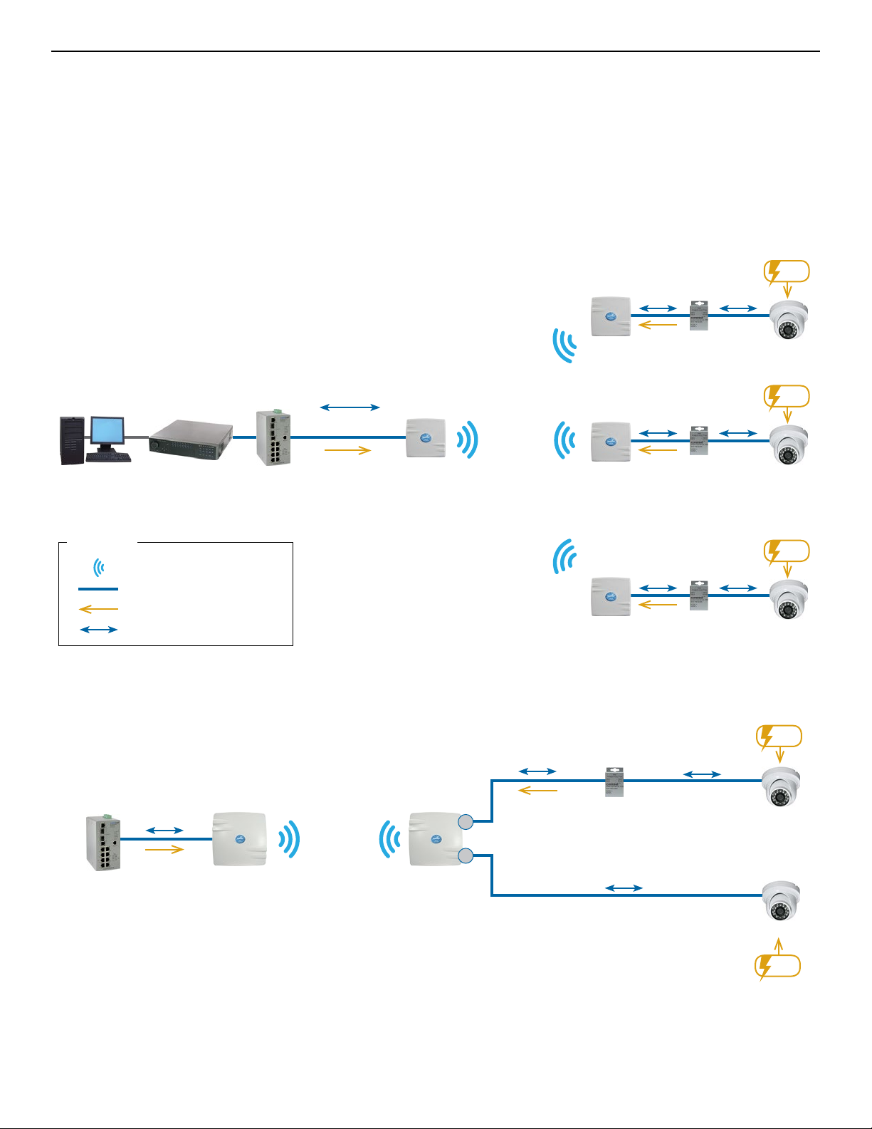
2.0 Point to Multi-Point
These individual units allow the user to configure for either multipoint access point or client operation.
There is a MAC address lock feature that can be enabled through the user interface but is not enabled
by default. The NW(1,2)/M includes a 16dBi 30° internal antenna and there is an optional 8dBi 70°
internal antenna. See the ComNet website for the latest information regarding antenna support.
Preconfigured NWK kits do not support point-to-multipoint topologies.
PC NVR ComNet Gigabit
Managed Switch
with 30W PoE+
LEGEND
WIRELESS
CAT5
POWER
ETHERNET DATA
10/100 Ethernet
PoE
NW1/M/IA870
(Recommended
Access Point)
NW1/M (Client)
NW1/M (Client)
NW1/M (Client)
PIM or other
PSE device
Ethernet Ethernet
PoE
PIM or other
PSE device
Ethernet Ethernet
PoE
PIM or other
PSE device
Ethernet Ethernet
PoE
Power
IP Camera
Power
IP Camera
Power
IP Camera
3.0 Point-to-Point Topology Utilizing Dual Ports
PIM or other
PSE device
Ethernet
ComNet Managed
Switch with 30W PoE
Connected to Network
10/100 Mbps
Ethernet
PoE
NW1/M
(Access Point)
NW1
(Client)
Ethernet
PoE
P1
P2
Power
Ethernet
IP Camera
IP Camera
Power
TECH SUPPORT: 1.888.678.9427
INS_NW(1,2)/M_REV– 06/10/13 PAGE 8
Page 9
INSTALLATION AND OPERATION MANUAL NW(1,2)/M
4.0 Cabling Requirements
Shielded CAT 5 or better should be used for all out of plant Ethernet connection and should
be properly grounded through the PoE AC ground. Industrial grade shielded Ethernet cable is
recommended to help prevent ESD damage commonly experienced with outdoor installations.
Visit www.comnet.net/comnet-products/cables
5.0 Hardware Installation
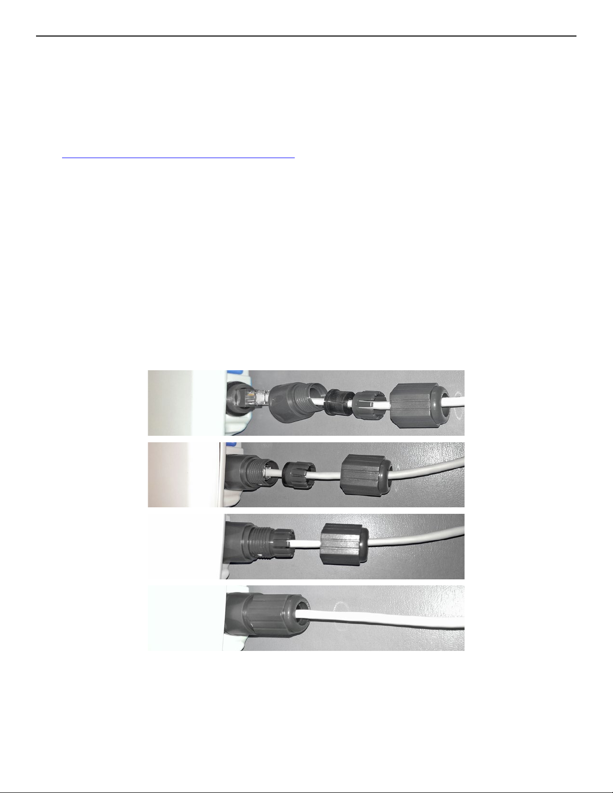
5.1 Outdoor Ethernet Gland Installation
There will be at least one cable gland included with each outdoor enclosure. Below is an image of
the individual parts of the gland with an Ethernet cable routed through.
Note: The split rubber washer allows a pre-terminated Ethernet cable to be used.
Once the cable has been routed through the weather connection, and the RJ45 connection has
been made, screw in the gland into the housing making sure it is tight enough for a water tight
seal. Push the split rubber gasket into place and loosely screw the cap that goes over the rubber
washer.
Once the gland is tight in the housing, tighten the outer nut/cap making sure the rubber seal
squeezes and seals the Ethernet cable to the gland as shown below.
TECH SUPPORT: 1.888.678.9427
INS_NW(1,2)/M_REV– 06/10/13 PAGE 9
Page 10
INSTALLATION AND OPERATION MANUAL NW(1,2)/M
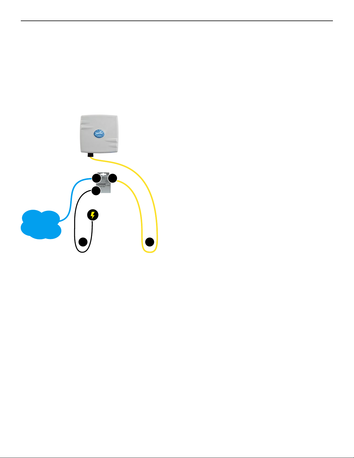
Connect one end of an RJ-45 Ethernet cable to the LAN OUT port of the Power Injection
Module (PIM) and the other end to LAN of the access point – as sown below.
Note: Maximum length of the RJ-45 CAT5 cable is 90 meters.
Connect the RJ-45 Ethernet cable attached to the PIM to a network device, such as a switch or
to the configuration PC. Then plug the power adaptor to an AC power outlet and power plug
into the socket of the PIM – as shown in the diagram below.
Note: DC Passive PoE input for the NW(1,2)/M and NWK(1,2)/M is 48 VDC.
A. Connect one end of an RJ-45 Ethernet cable to the OUT
port of the Power Injection Module (PIM) and the other end
to LAN of the access point.
Maximum length of the RJ-45 CAT5 cable is 100 meters.*
B. Connect the RJ-45 Ethernet cable attached to the PIM to a
network device, such as to a switch or to the PC you will use
to configure the access point.
Ethernet
Network
A
B
C
C. Connect the power adaptor to the main electrical supply
and the power plug into the socket of the PIM.
PoE power input: Passive PoE (range 42 to 56 VDC).
The unit can also be powered by a suitable IEEE 802.3af/at
PSE device such as a PoE switch or injector.
D. A Drip Loop is recommended as additional precaution
against moisture entering the Access Point housing.
DD
* Up to 200mW radio. For higher power radio upgrade to higher rating
power adapter.
TECH SUPPORT: 1.888.678.9427
INS_NW(1,2)/M_REV– 06/10/13 PAGE 10
Page 11
INSTALLATION AND OPERATION MANUAL NW(1,2)/M
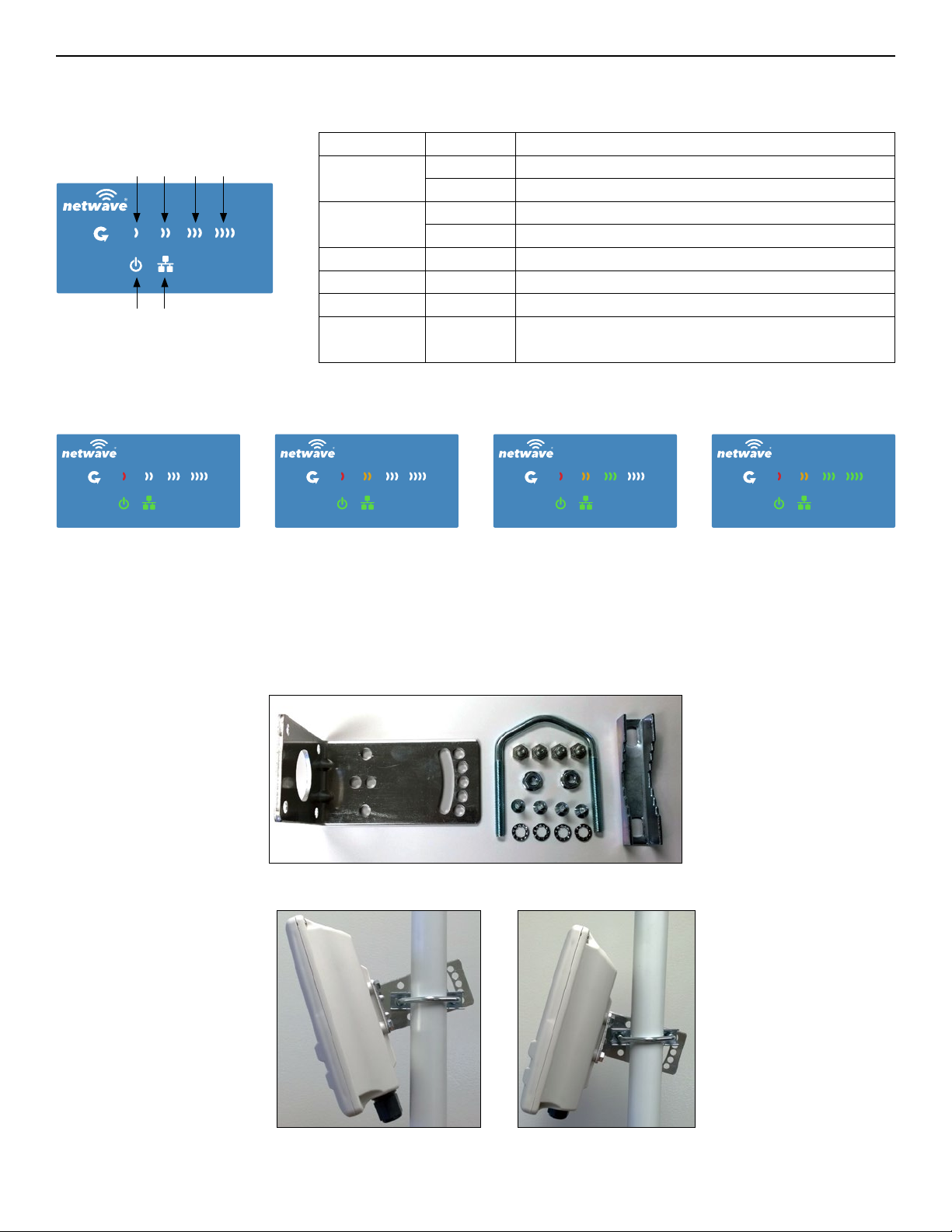
5.2 NW1/M and NW2/M Indicating LED Details
LED VISUAL CUE INDICATION
RSSI1POWER
RSSI2LAN
RSSI3
RSSI4
POWER
LAN
RSSI1 SOLID RED Weak Connection
RSSI2 SOLID ORANGE Moderate Connection
RSSI3 SOLID GREEN Solid Connection
RSSI4 SOLID GREEN
SIGNAL STRENGTH:
SOLID GREEN Power is supplied to the unit
OFF No power is supplied to the unit or the unit is in reset.
SOLID GREEN LAN Connected
OFF No Connectivity
Excellent Connection
(Advisable to check Status Page to confirm RSSI is > -55)
WEAK SIGNAL EXCELLENT SIGNAL
5.3 Outdoor Standard Mounting Hardware
This mounting hardware will support pole diameters up to 2 in (5.8 cm). Below are the parts
contained in the standard mounting hardware.
Here is the mounting hardware assembled shown in a +30° and -30°vertical position
TECH SUPPORT: 1.888.678.9427
INS_NW(1,2)/M_REV– 06/10/13 PAGE 11
Page 12

INSTALLATION AND OPERATION MANUAL NW(1,2)/M
6.0 Key Default Configurations
IP Address of Web Server 192.168 .10.10 0 (N WK X _ A P)
192.168 .10.101 for all ot her s
LAN Mode for Web Server Static Addressing
Web Server User ID admin
Web Server Password admin
SSID Net Wave -1
WPA Pre-shared Key 12345678
Channel-Frequency (AP) Auto
Channel Spectrum Width 20/40M
Long Range Parameters Enabled and defaulted to 1000m
Note: A Reset to defaults (performed on the ADMIN page or via the RESET button) will erase all
user configurations.
TECH SUPPORT: 1.888.678.9427
INS_NW(1,2)/M_REV– 06/10/13 PAGE 12
Page 13

INSTALLATION AND OPERATION MANUAL NW(1,2)/M
7.0 Quick Configuration
1. Connect an Ethernet cable from the port labelled as IN on the power Injection Module to
either a laptop or a PC LAN port.
2. Connect the second Ethernet cable from the OUT port on the Power Injection Module to the
NetWave LAN port.
3. Apply 48 VDC to the Power Injection Module with the provided power supply. You should
notice the green LED illuminate in the Power Injection Module and the power LED on the
NetWave unit.
4. Set the IP address of the laptop being used to configure NetWave to static and the subnet to
192.168 .10. x /24 s ubnet .
5. Point the browser to 192.168.10.101. This is the default address.
For preconfigured kits (NWKX_AP and NWKX_CL) point the Browser to 192.168.10.100 for the
Access Point or 192.168.10.101 for the Client.
6. A login prompt will pop up. Enter:
Username admin
Password admin
7. Select the NETWORK » WIFI tab and set the desired network settings.
Select Apply & Save
Note: This will be the network address for the NetWave web server. It is not necessary to set to
the same subnet as the operating network but it is recommended.
8. Select the NETWORK -> WIFI tab and set:
• Wireless mode – Set to AP or Client
• Country code – Only required if setting up the NW2/M (ETSI) model
Note: It is the user’s responsibility to ensure that the correct country is chosen. ComNet
accepts no liability for incorrect equipment set up.
• Output RF power – if received signal strength is greater than -40 dBm, it is recommended to
reduce RF TX power
• Set SSID – if changing from the default setting
• Channel Spectrum Width – May want to reduce to 20M from the default 20/40M if the 5GHz
spectrum is crowded
• Wireless Security – if changing from default settings
• Select Apply Settings
• Select Save
Note: NW1/M and NW2/M Multipoint nodes will need to have the Wireless Mode set to either
AP or Client (default is Client). And the IP addresses will need to be all set to different
addresses (default address is 192.168.10.101). Once this is done, all the clients will connect
to the multipoint AP with all other setting kept at default.
TECH SUPPORT: 1.888.678.9427
INS_NW(1,2)/M_REV– 06/10/13 PAGE 13
Page 14

INSTALLATION AND OPERATION MANUAL NW(1,2)/M
TECH SUPPORT: 1.888.678.9427
INS_NW(1,2)/M_REV– 06/10/13 PAGE 14
Page 15

INSTALLATION AND OPERATION MANUAL NW(1,2)/M
Detailed Configuration
8.0 Getting Started
To access the NetWave configuration interface, perform the following steps:
1. Connect the local area network (LAN) port of the router to the network port of your computer
using an Ethernet cable. Ethernet cables are also known as LAN cables or network cables.
They connect devices such as computers, routers, and switches on wired networks.
2. Next, take the power adapter that comes with the set and connect it to a power socket as well
as the router. Turn on the power.
3. Assign the Ethernet adapter on your computer with a static IP address on the 192.168.1.x
network, e.g. 192.168.10.10 and with a subnet mask 255.255.255.0.
4. Launch a web browser and enter the default IP address of the router, 192.168.10.101, into the
address bar.
The first page that you see is the login page. The words on the top left denote the hardware part
number and the firmware build version e.g. NW1 NW1_v1.78.0
The login page is presented upon requesting the Netwave Radio’s IP address.
The default authorization details are:
Username: admin
Password: admin
TECH SUPPORT: 1.888.678.9427
INS_NW(1,2)/M_REV– 06/10/13 PAGE 15
Page 16
INSTALLATION AND OPERATION MANUAL NW(1,2)/M
8.1 Operating Modes
The Netwave Radio can operate in the following modes:
1. Access Point WDS
2. Station (Client) WDS
In a commonly used setup, the WAN port of an access point connects to a modem via an Ethernet
cable. A modem can be a cable, digital subscriber line (DSL), or fiber optic modem. A modem
translates the signal from the internet service provider (ISP) to Ethernet signals that the access
point can understand. This allows the access point to have internet connection.
Other devices called stations connect wirelessly to this access point. These devices can be
mobile phones, printers, IP cameras, laptops, or even other routers. The stations obtain internet
connection from the access point.
An access point WDS and a station WDS together extend the wireless coverage, like a repeater.
8.2 Buttons and Alerts
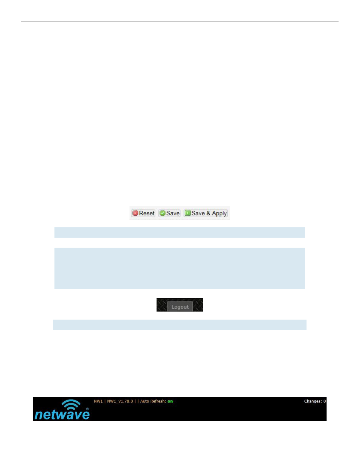
The buttons are described here.
Reset Undo the changes.
Save Saves the changes but does not take effect till settings are applied
Save & Apply Saves and applies the changes.
Please use this button instead of the 'Save' button so that the
changes would be applied immediately.
It is recommended to click this button before moving to a different
page.
Logout Logs out of the router's web page.
Note: At the top right corner of the NetWave configuration web page, there may be either of the
following texts displayed:
Changes: 0: Means that all changes on the configuration web page have been applied to
the Wireless Device.
Unsaved Changes: Shows the number of changes that have not yet been Save & Apply.
TECH SUPPORT: 1.888.678.9427
INS_NW(1,2)/M_REV– 06/10/13 PAGE 16
Page 17

INSTALLATION AND OPERATION MANUAL NW(1,2)/M
8.2.1 Reset Button
The reset button is a physical hardware button on the board.
Please refer to Section "Reset Button."
8.2.2 Indicating LEDs
The light emitting diodes (LEDs) on the board are described in Section "LEDs on the Board".
8.2.3 Buzzer
The new NetWave buzzer makes the following sounds:
• Power up: Beep once.
• End of Firmware Loading: Beep twice.
• Alignment: Beep according to signal thresholds defined. The alignment buzzer is described in
Section "Link Status (for Station Mode)".
TECH SUPPORT: 1.888.678.9427
INS_NW(1,2)/M_REV– 06/10/13 PAGE 17
Page 18
INSTALLATION AND OPERATION MANUAL NW(1,2)/M
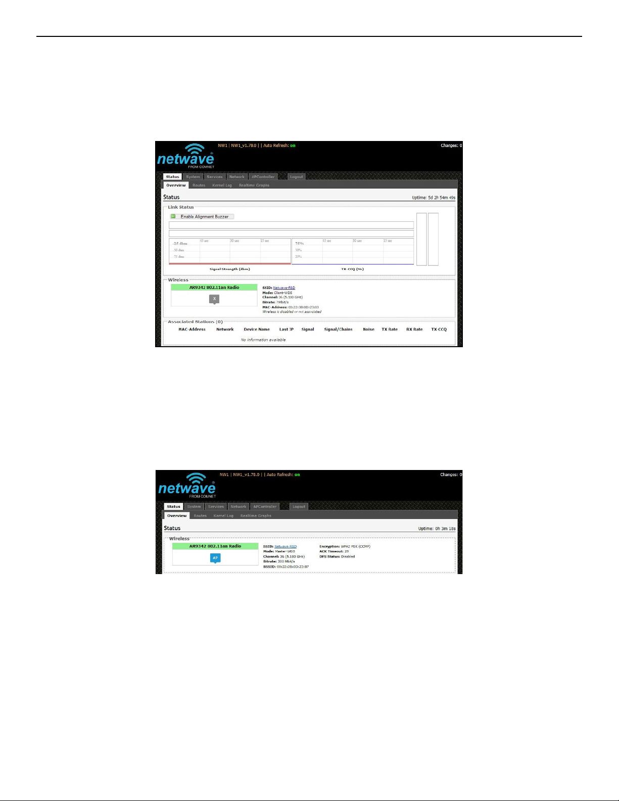
9.0 Status Tab
After login, when you click on the Status top-level tab, you can see the second-level tabs of
Overview, Routes, System Log, Kernel Log, and Real-time Graphs. This is shown in Figure 2.
Figure 2: The Status Tab.
9.1 Overview
The Status » Overview page is divided into the sections Wireless, Associated Stations, System,
Memory, Network, and DHCP Leases.
Uptime: Displays the duration of time since the router was turned on or rebooted.
Figure 3: The Status » Overview page.
TECH SUPPORT: 1.888.678.9427
INS_NW(1,2)/M_REV– 06/10/13 PAGE 18
Page 19
INSTALLATION AND OPERATION MANUAL NW(1,2)/M
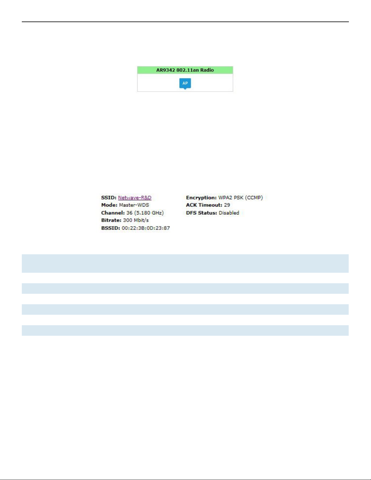
9.2 Wireless
The wireless chipset model is shown in the little box on the left e.g. AR9342 802.11an Radio.
Figure 4: Wireless chipset model.
The characters AP in the small callout box means that the radio is operating in the Access Point
(AP) mode. If the characters are CPE, it means that the radio is operating as a customer-premises
equipment (CPE) i.e. a station. The character X is shown if the radio is disabled.
9.3 Wireless (for AP Mode)
The Wireless section in the Status » Overview page shows a summary of the wireless parameters.
The following describes the parameters when the device is in the AP mode.
Figure 5: A summary in the Wireless section for a device operating as an 802.11 access point.
SSID Displays the name of the wireless network that this access point (AP) is offering, the Service
Set Identifier (SSID).
Mode This is 'Master' if the device is in AP WDS mode.
Channel Shows the channel number and frequency that this AP is using.
Bitrate This is the maximum bitrate supported by the radio in the current configuration.
BSSID This is the MAC address of the AP's radio.
Encryption Displays the wireless encryption used.
ACK Timeout Shows the maximum acknowledgment time in microseconds.
DFS Status If DFS is enabled, the AP automatically switches channel if radar is detected on the current
channel.
TECH SUPPORT: 1.888.678.9427
INS_NW(1,2)/M_REV– 06/10/13 PAGE 19
Page 20

INSTALLATION AND OPERATION MANUAL NW(1,2)/M
9.4 Wireless (for Station Mode)
The following describes the parameters for a device operating in Station mode.
Figure 6: A summary in the Wireless section for a device operating as an 802.11 station.
SSID Displays the name of the wireless network that this station should be associated with.
Mode This is 'Client' if the device is in Station WDS mode.
Channel Shows the channel number and frequency that this station is using. Normally, it would
automatically select the same channel as the AP.
Bitrate This is the maximum bitrate supported by the radio in the current configuration.
MAC-Address States the MAC address of the device's radio.
BSSID This is the MAC address of the AP's radio.
Encryption Displays the wireless encryption used.
ACK Timeout Shows the maximum acknowledgment time in microseconds.
DFS Status If DFS is enabled, the AP automatically switches channel if radar is detected on the
current channel.
TX-CCQ Displays the transmission quality in %. A higher percentage means a better wireless
connection quality.
RX Rate Shows the receive bit rate of this station.
TX Rate Shows the transmit bit rate of this station.
TECH SUPPORT: 1.888.678.9427
INS_NW(1,2)/M_REV– 06/10/13 PAGE 20
Page 21

INSTALLATION AND OPERATION MANUAL NW(1,2)/M
9.5 Associated Stations (for AP Mode)
This section shows the connected devices, if the Radio is in the AP mode.
Figure 7: List of Associated Stations.
If there are no associated stations, the text “No information available” is displayed. The parameters
shown are as follows:
MAC-Address Displays the MAC address of the station's radio.
Network States the name of the wireless network.
Device Name Shows the name of the station.
Last IP States the most recent IP address of the station as seen by the Radio.
Signal Displays the received signal strength from the station e.g. -31 dBm.
Signal/Chains Shows the received signal strengths from the station on each antenna e.g. -52, -35, -34 dBm.
The value of -95 dBm is taken to mean “no antenna” if the radio has only 2 antennas.
Noise Displays the received noise power at the AP.
TX Rate Shows the transmit bit rate from the AP towards this station.
RX Rate Shows the receive bit rate at the AP from this station.
TX-CCQ Indicates the wireless connection quality.
9.6 System
This section shows the Router Name, Router Model,
Firmware Version, Kernel Version, and Local Time.
Figure 8: System parameters.
9.7 Memory
Here, the Total Available and Free memory are shown.
TECH SUPPORT: 1.888.678.9427
Figure 9: Total Available and Free Memory.
INS_NW(1,2)/M_REV– 06/10/13 PAGE 21
Page 22
INSTALLATION AND OPERATION MANUAL NW(1,2)/M
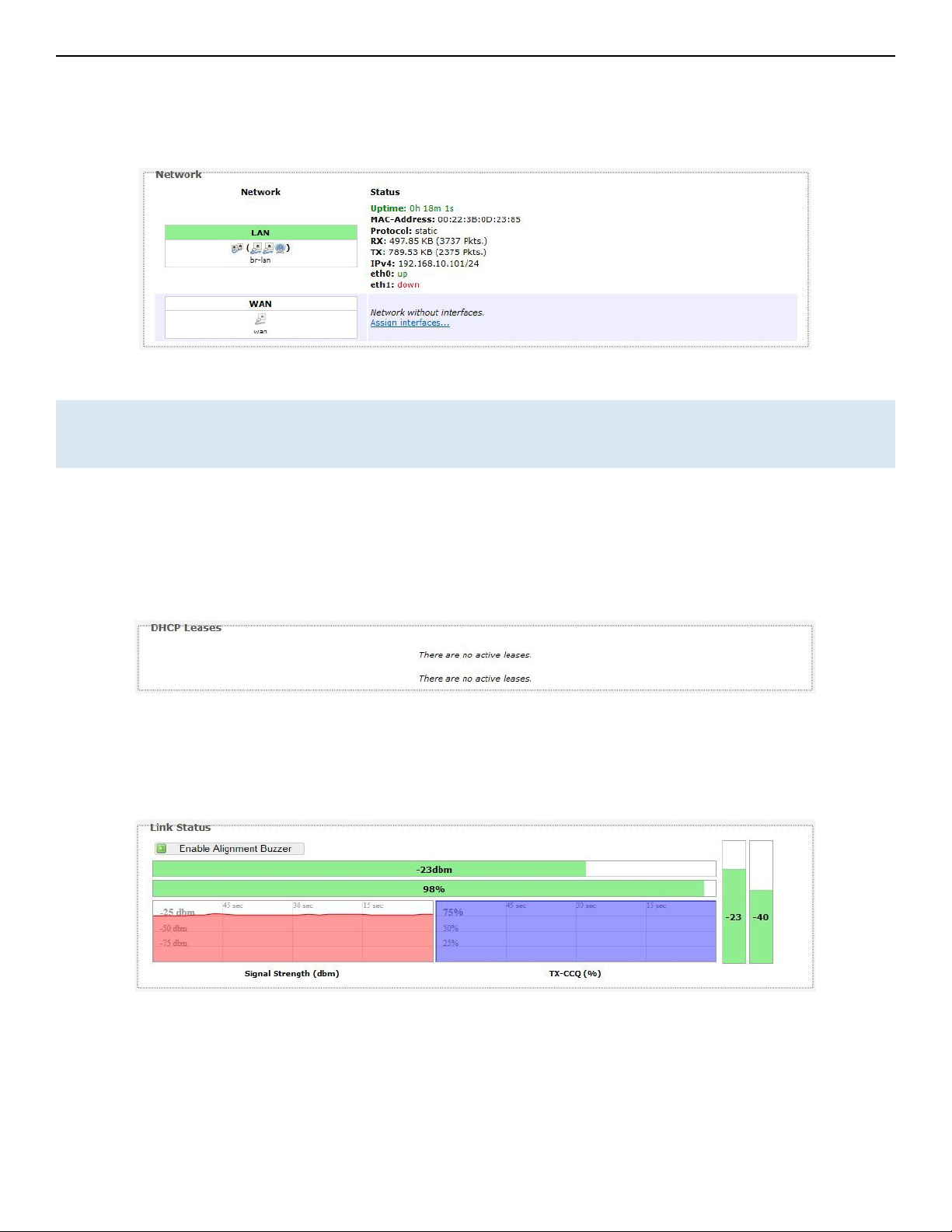
9.8 Network
This section displays the status of the LAN and WAN networks.
Figure 10: Network summary.
Status: Shows summaries of the interfaces for the LAN and WAN zones. This may include uptime, MAC
address, protocol, bytes and packets received by the device, bytes and packets transmitted by
the device, and its IPv4 address.
9.9 DHCP Leases
This section shows a table of MAC and IP addresses of connected computers with static DHCP
leases. They are specified in the Network » Interfaces » LAN » Static Leases section of the device's
configuration web page.
Figure 11: Currently active static DHCP leases.
9.10 Link Status (for Station Mode)
This section only applies if the device operates as an 802.11 station.
Figure 12: The Link Status section.
In the Link Status section on the Status » Overview web page, the value in the top left box denotes
the current received signal strength e.g. -48 dBm. The box directly below it shows the current
TX-CCQ (transmission client connection quality) e.g. 71 %. The bottom left box shows a real-time
graph of the received signal strength over the last 60 seconds.
TECH SUPPORT: 1.888.678.9427
INS_NW(1,2)/M_REV– 06/10/13 PAGE 22
Page 23

INSTALLATION AND OPERATION MANUAL NW(1,2)/M
The box directly to its right shows a real-time graph of the TX-CCQ over the past 60 seconds.
On the right of this section, there are 3 vertical bars. Each bar shows the current received signal
strength of each antenna e.g. -53 dBm, -44 dBm, and -48 dBm. If the radio has only 2 antennas,
the third vertical bar is given a default value of -95 dBm.
Enable Alignment
Buzzer
When enabled, the board would continually emit beeping sounds to indicate the
received signal strength. Every 3 seconds, the board would emit a number of beeps
(1 to 4) in quick succession. The number of beeps is the same as the number of lighted
Signal strength indicator LEDs. See Section " LED Configuration." Just like for the
LEDs, more beeps indicate a higher received signal strength. This is useful for a person
aligning directional antennas at a height, in an outdoor scenario, if the LEDs are not
visible. Another person on the ground could adjust the threshold values for the LEDs.
There is some delay before the received signal strength gets reported by the alignment
buzzer. To turn off the beeping sounds, click the button “Disable Alignment Buzzer”.
9.11 Ro ute s
When you click on the Status » Routes tab, you would see the page that shows the routing rules
that are currently active on the device.
Figure 13: The Status » Routes page.
ARP This address resolution protocol (ARP) table shows the IP address and corresponding
MAC address of each device on the network.
Active IPv4-Routes This table shows the IPv4 gateway and network ID (Target) for each subnet.
TECH SUPPORT: 1.888.678.9427
INS_NW(1,2)/M_REV– 06/10/13 PAGE 23
Page 24

INSTALLATION AND OPERATION MANUAL NW(1,2)/M
9.12 Kernel Log
This page shows the kernel debugging messages. This kernel log can also be obtained by typing
“dmesg” in a serial console such as Tera Term if a suitable serial connector is used.
Figure 14: The Status » Kernel Log page.
TECH SUPPORT: 1.888.678.9427
INS_NW(1,2)/M_REV– 06/10/13 PAGE 24
Page 25

INSTALLATION AND OPERATION MANUAL NW(1,2)/M
9.13 Real-time Graphs
Under the tab for Real-time Graphs, there are four tabs titled Load, Traffic, Wireless, and
Connection.
9.13 .1 Lo ad
Figure 15: The graph for Real-time Load.
TECH SUPPORT: 1.888.678.9427
INS_NW(1,2)/M_REV– 06/10/13 PAGE 25
Page 26

INSTALLATION AND OPERATION MANUAL NW(1,2)/M
9.13 .2 Tra ffic
9.13 .3 Wir eless
Figure 16: The graph for Real-time Traffic.
TECH SUPPORT: 1.888.678.9427
Figure 17: The graph for Real-time Wireless.
INS_NW(1,2)/M_REV– 06/10/13 PAGE 26
Page 27
INSTALLATION AND OPERATION MANUAL NW(1,2)/M
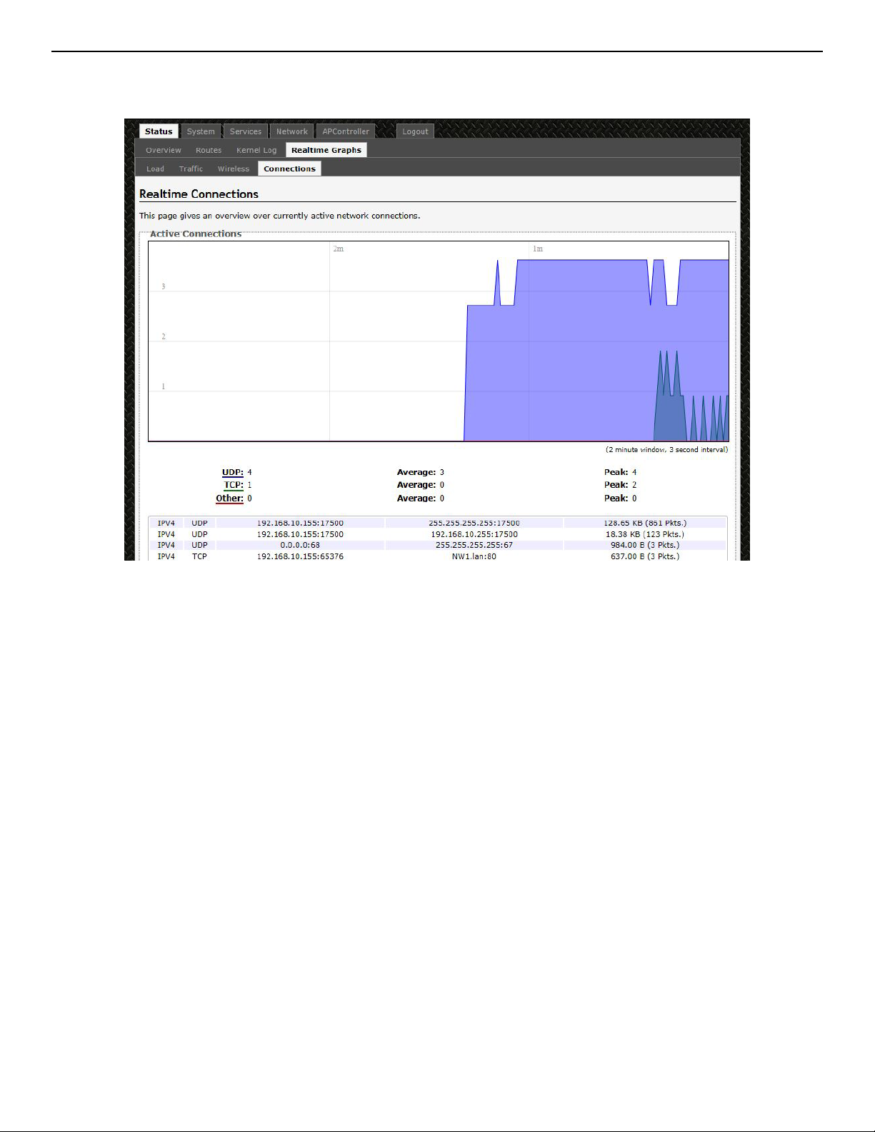
9.13.4 Connection
Figure 18: The graph for Real-time Connections.
TECH SUPPORT: 1.888.678.9427
INS_NW(1,2)/M_REV– 06/10/13 PAGE 27
Page 28

INSTALLATION AND OPERATION MANUAL NW(1,2)/M
10.0 System Tab
This section is about the System top-level tab.
Under this tab, there is a row of tabs for
Administration, Services, SNMP, LED Configuration,
Backup/Flash Firmware, and Reboot. This can be seen in Figure 18.
Figure 19: The System top-level tab.
Within the System page, you can configure the device parameters such as the hostname and time
zone.
10.1 System Properties
Within the section on System Properties, there are tabs corresponding to General Settings,
Logging, and Language and Style.
General Settings
Local Time Displays the local time according to the time zone.
Hostname Configures the name of the device.
Time Zone Sets the time zone.
TECH SUPPORT: 1.888.678.9427
INS_NW(1,2)/M_REV– 06/10/13 PAGE 28
Page 29
INSTALLATION AND OPERATION MANUAL NW(1,2)/M
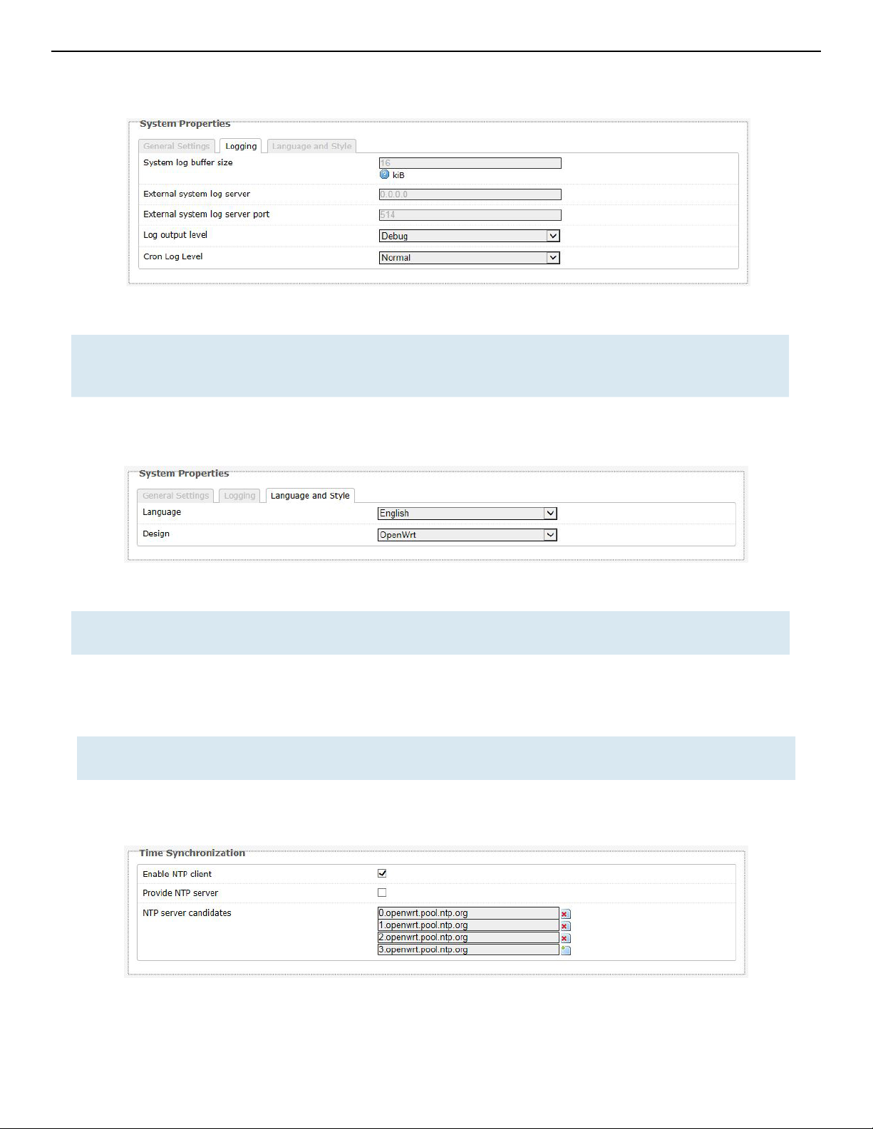
Logging
Figure 20: Changing the system properties for Logging.
Logging Specifies parameters used for the system log, such as System log buffer size, External
system log server, External system log server port, Log output level, and Cron Log
Level.
Language and Style
Figure 21: Modifying the Language and Style.
Language
and Style
Lets you choose the language and design of the router's web pages.
10.2 Time Synchronization
Enable NTP
client
NTP server
candidates
Obtains the date and time from specified Network Time Protocol (NTP) servers.
These are the sources of the time information. At least three are recommended for
accurate time synchronization.
TECH SUPPORT: 1.888.678.9427
Figure 22: Time Synchronization settings.
INS_NW(1,2)/M_REV– 06/10/13 PAGE 29
Page 30

INSTALLATION AND OPERATION MANUAL NW(1,2)/M
10.3 Administration
Within the System » Administration page, you can configure the Router Password, SSH, Telnet,
Web, and FTP settings.
10.3.1 Router Password
Figure 23: Setting the router password.
Password Allows you to set the Router password, the default being password.
Confirmation Requires you to re-enter the password.
10. 3.2 SSH
Figure 24: SSH settings in the System » Administration page.
SSH Allows you to access the router's Linux shell and file system using the Secure
Shell protocol. For example, the programs PuTTY and WinSCP can be used.
Interface Lets the device listen on a given interface or all interfaces.
Port Specifies the listening port, the default being 22.
Password
authentication
Allows SSH password authentication.
Allow root logins
with password
Gateway ports Allow remote hosts to connect to local SSH forwarded ports.
TECH SUPPORT: 1.888.678.9427
This is enabled by default.
INS_NW(1,2)/M_REV– 06/10/13 PAGE 30
Page 31
INSTALLATION AND OPERATION MANUAL NW(1,2)/M
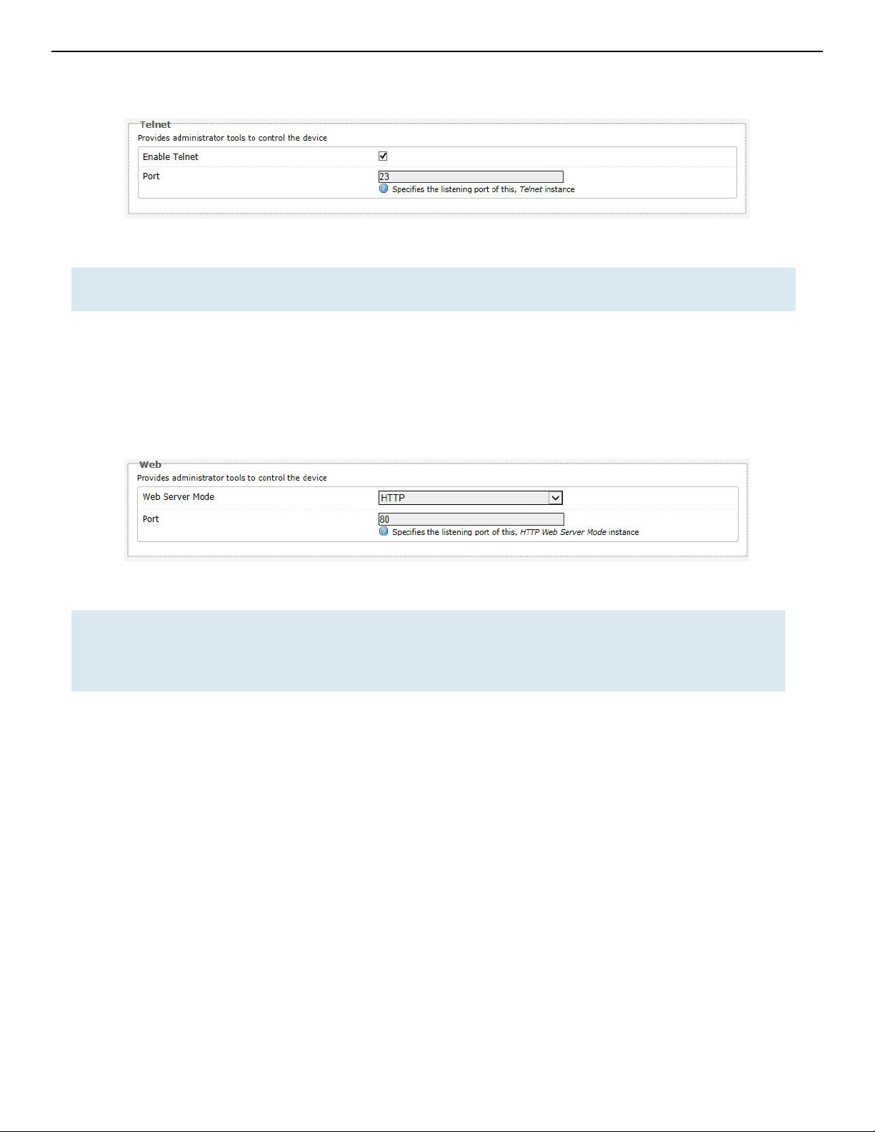
10.3.3 Telnet
Figure 25: Telnet settings in the System » Administration page.
Telnet Provides administrator tools for controlling the device or network debugging, over an
unencrypted connection.
Port Specifies the listening port, the default being 23.
To start using Telnet, enter the command “telnet 192.168.10.101” or “telnet 192.168.10.101 23”
into a Command Prompt if using Windows, or into a Terminal if using Linux or Mac OS X.
10. 3.4 Web
Figure 26: The router's web server mode and port.
Web Server
Mode
This can be set to Hypertext Transfer Protocol (HTTP) or Hypertext Transfer Protocol
Secure (HTTPS). For HTTPS, if you see the warning, “The certificate is not trusted
because it is self-signed. The certificate is only valid for OpenWRT,” click “Add
Exception”, “Confirm Security Exception” and proceed.
Port Specifies the listening port, the default being 80 for HTTP and 443 for HTTPS.
TECH SUPPORT: 1.888.678.9427
INS_NW(1,2)/M_REV– 06/10/13 PAGE 31
Page 32
INSTALLATION AND OPERATION MANUAL NW(1,2)/M
10.4 Services
In the System» Services page, you can configure the Ping Watchdog and the Auto Reboot.
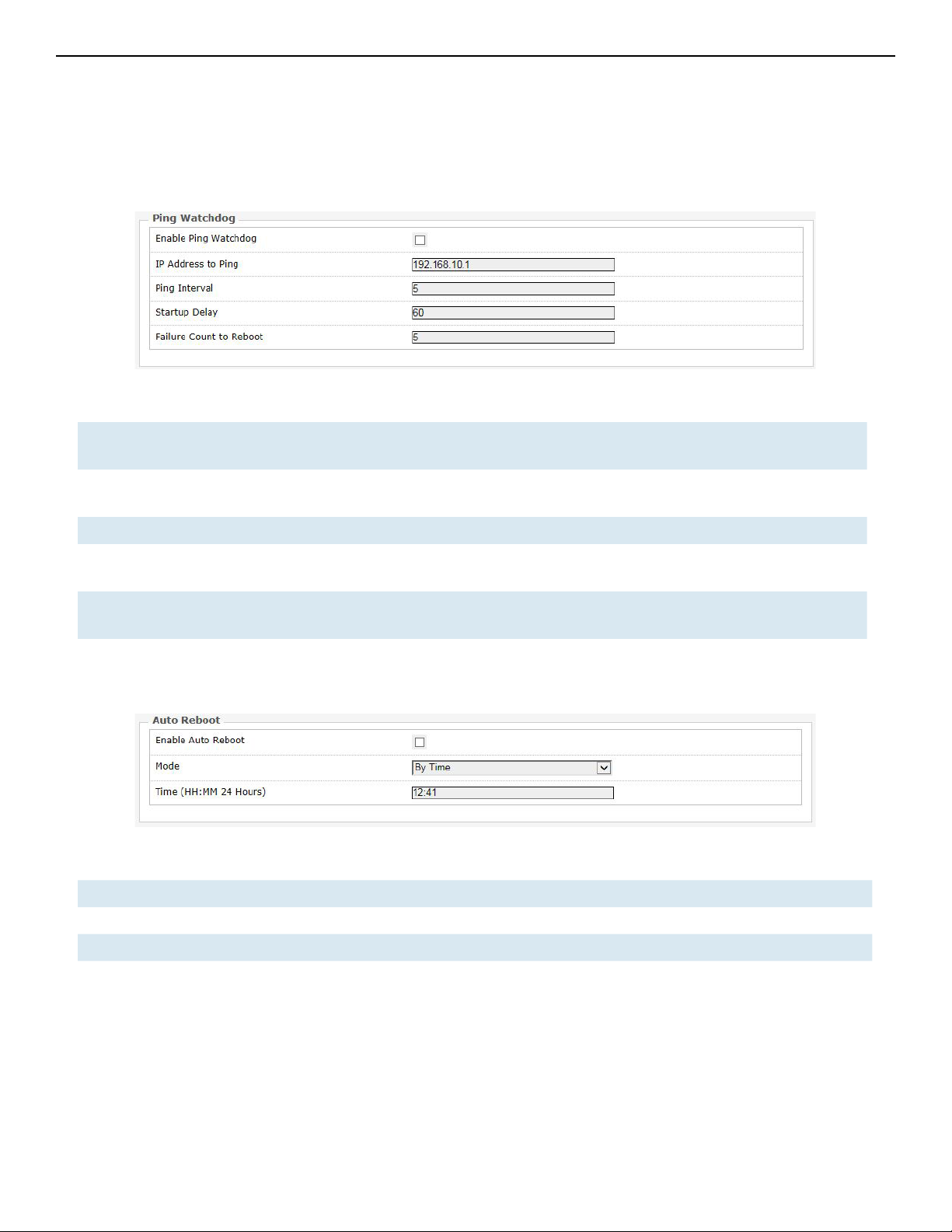
10.4.1 Ping Watchdog
Figure 27: Ping Watchdog settings in the System » Services page.
Ping
Watchdog
IP Address
to Ping
Ping Interval Specifies the time between successive pings, the default being 5 seconds.
Startup
Delay
Failure Count
to Reboot
Configures the device to ping to a remote IP address and reboot if the connection is
lost. It is disabled by default.
Sets the remote IP address to ping e.g. 192.168.10.10 or 8.8.8.8.
Sets the time delay after the router finishes rebooting, before running the Ping
Watchdog, the default being 60 seconds.
Specifies the number of failed pings before the router reboots automatically.
10.4.2 Auto Reboot
Figure 28: Auto Reboot settings in the System » Services page.
Auto Reboot Allows the router to reboot itself automatically, disabled by default.
Mode Chooses the Auto Reboot mode by Time or by Number of Hours.
Time Sets the time of day to reboot if the Mode is by Time.
Number of
Hours
TECH SUPPORT: 1.888.678.9427
Sets the delay as an integer number of hours after each reboot, if the Mode is by
Number of Hours.
INS_NW(1,2)/M_REV– 06/10/13 PAGE 32
Page 33

INSTALLATION AND OPERATION MANUAL NW(1,2)/M
10.5 SNMP
The Simple Network Management Protocol (SNMP) is an Internet-standard protocol for managing
devices on IP networks. It consists of a set of standards for network management, including
an application layer protocol, a database schema, and a set of data objects. SNMP exposes
management data in the form of variables on the managed systems, which describe the system
configuration. These variables can then be queried (and sometimes set) by managing applications.
In the System » SNMP Page, you can configure SNMP V2c and SNMP V3.
10.5.1 SNMP Information
In the SNMP Information section, the text fields for the SNMP Enterprise ID, Contact, and Location
information are shown.
10.5.2 SNMP Configuration
General Settings
Figure 29: General settings for SNMP.
Enable SNMP Enables SNMP.
SNMP V2c Read Password Sets the community string for read-only access (to the variables on the
SNMP agent) by the network management station (NMS). The NMS is
the software which runs on the SNMP manager. (default: public)
SNMP V2c Write Password Sets the community string for read-write access by the SNMP
manager. (default: private)
A community string identifies a group of SNMP agents. It is sent in clear
text. It should be changed from the default string “public” or “private”. The
variables on the SNMP agent can be classified into read-only or read-write
variables.
SNMP V3 Username Sets the username for authentication. (default: admin)
SNMP V3 Auth Algorithm Shows the authentication algorithm used e.g. MD5.
SNMP V3 Auth Password Configures the password for user authentication. (default: password)
SNMP V3 Privacy Algorithm Shows the data encryption algorithm used e.g. DES.
TECH SUPPORT: 1.888.678.9427
INS_NW(1,2)/M_REV– 06/10/13 PAGE 33
Page 34

INSTALLATION AND OPERATION MANUAL NW(1,2)/M
SNMP V3 Privacy Password Sets the password for data encryption. (default: password)
Trap
Figure 30: SNMP trap configuration.
Enable SNMP Trap Allows the SNMP agent to notify the SNMP manager of events.
SNMP Trap IP Address Sets the IP address of the SNMP manager which receives the trap
messages.
SNMP Trap Port Sets the port number.
10.6 Reset Button
The reset button is a physical hardware button on the AP hardware board. Depending on how
long the button is pressed, you can reboot the board or reset it to factory default. First make
sure that the power is on and wait a minute for the board to finish starting up. The following table
shows the duration of the button press and the corresponding action.
Button Press Duration Effect
0 - 3 seconds Reboot
4 - 30 seconds Reset to factory default
TECH SUPPORT: 1.888.678.9427
INS_NW(1,2)/M_REV– 06/10/13 PAGE 34
Page 35

INSTALLATION AND OPERATION MANUAL NW(1,2)/M
10.7 Indicating LEDs
10.7.1 LED Configuration for Signal
Strength Indicator LEDs #1 to #4
The System » LED Configuration page customizes how the LEDs indicate the received signal strength.
Signal strength
Chooses the Wireless interface, which is the wireless network name.
indicator interface
Signal strength
indicator LEDs
Sets the received signal strength thresholds (in dBm) above which RSSI LEDs #1 to #4
would light up.
Figure 31: Signal strength indicator LEDs and their default threshold values in dBm.
10.7.2 Summary of the LED Indicators
LED VISUAL CUE INDICATION
RSSI1POWER
RSSI2LAN
RSSI3
RSSI4
POWER
LAN
RSSI1 SOLID RED Weak Connection
RSSI2 SOLID ORANGE Moderate Connection
RSSI3 SOLID GREEN Solid Connection
RSSI4 SOLID GREEN
SOLID GREEN Power is supplied to the unit
OFF No power is supplied to the unit
SOLID GREEN LAN Connected
OFF No Connectivity
Excellent Connection
(Advisable to check Status Page to confirm RSSI is > -55)
SIGNAL STRENGTH:
WEAK SIGNAL EXCELLENT SIGNAL
TECH SUPPORT: 1.888.678.9427
INS_NW(1,2)/M_REV– 06/10/13 PAGE 35
Page 36

INSTALLATION AND OPERATION MANUAL NW(1,2)/M
10.8 Backup/Flash Firmware
The System » Backup/Flash Firmware page lets you perform backup and restore, or flash a new
firmware.
10.8.1 Backup/Restore
Download backup Generate archive: Downloads a tar archive of the current configuration files.
Note: The backup archive file should be stored in a safe place because it contains the wireless
password in clear text.
Reset to defaults Perform reset: Resets the firmware to its initial state.
Restore backup Upload archive: Lets you upload a previously generated backup archive to restore
configuration files.
10.8.2 Flash new firmware
You can upload a new firmware to replace the currently running firmware.
Keep settings Retains the current configuration.
Firmware Shows the current version of the firmware and allows you to upload a new firmware.
10.9 Reboot
Perform reboot Reboots the operating system of your device. This is similar to the power-off and
power-on cycle. The system configuration remains the same. Any changes that are not
applied are lost.
TECH SUPPORT: 1.888.678.9427
INS_NW(1,2)/M_REV– 06/10/13 PAGE 36
Page 37

INSTALLATION AND OPERATION MANUAL NW(1,2)/M
11.0 Network Tab
You can view and configure the interfaces of the local area network (LAN) zone as well as the wide
area network (WAN) zone. Network address translation (NAT) occurs between these two network
zones. The router that performs the NAT is called a gateway. A gateway is a network point that
acts as an entrance to another network.
Figure 32: The Network top-level tab.
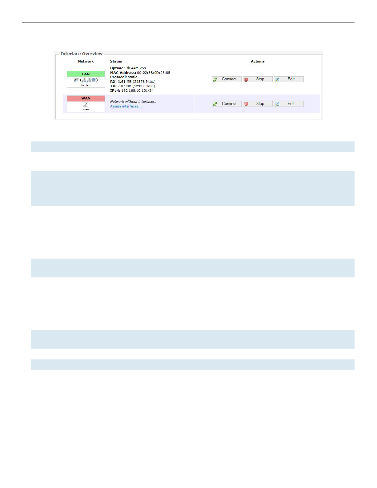
Figure 33: The Interface Overview on the Network » Interfaces page.
The Network column shows that the WAN zone has the physical port “eth1” as its interface.
In Figure 33, the LAN zone (icon with two Ethernet ports) has the bridged interface “br-lan” which
consists of one physical port (icon with one Ethernet port) and two wireless networks (each icon
looking like a short standing fan) on the device. Hovering the mouse over each icon would give
the name of the interface it represents.
TECH SUPPORT: 1.888.678.9427
INS_NW(1,2)/M_REV– 06/10/13 PAGE 37
Page 38

INSTALLATION AND OPERATION MANUAL NW(1,2)/M
11.1 Interfaces – WAN
The Network » Interfaces » WAN page configures the interface for the WAN zone.
11.1.1 Common Configuration
General Setup
Status Shows a summary of the interface for the WAN zone. This includes uptime, MAC address,
bytes and packets received by the device, bytes and packets transmitted by the device,
and its IPv4 address.
Figure 34: Status of the “eth1” interface of the WAN zone.
Protocol Chooses between DHCP client (default), where the device obtains it IP address
automatically, or Static address, where you can specify the device IP address. Other
protocols are PPTP, PPPoE, and L2TP.
Protocol – Static address
IPv4 address Sets the IP address of the device as seen from the WAN zone.
IPv4 netmask Sets the subnet mask e.g. 255.255.255.0. The IP address and netmask together
determine the subnet or network ID e.g. 192.168.10.0/24. Two devices must be in
the same subnet in order to establish a (Layer 2) link between them.
IPv4 gateway Specifies the IP address of the remote router that allows the device's shell to gain
internet access.
IPv4 broadcast Specifies the IPv4 broadcast address, optional.
Use custom DNS
servers
Configures the IP address of the DNS servers e.g. 165.21.100.88 for the SingNet
DNS server in Singapore or 8.8.8.8 for the Google DNS server in the USA. The
computers in the same subnet as this device can then set this device's IP address as
their preferred DNS server to obtain the same DNS service.
TECH SUPPORT: 1.888.678.9427
INS_NW(1,2)/M_REV– 06/10/13 PAGE 38
Page 39

INSTALLATION AND OPERATION MANUAL NW(1,2)/M
Protocol – DHCP client
The Dynamic Host Configuration Protocol (DHCP) is a standardized networking protocol used
by servers on an IP network to allocate IP addresses automatically to client devices.
Hostname to send
when requesting
DHCP
Specifies the name of this device as seen by the remote DHCP server.
Protocol – PPTP
The Point-to-Point Tunneling Protocol (PPTP) is a method for implementing virtual private
networks. PPTP uses a control channel over Transmission Control Protocol (TCP) and a Generic
Routing Encapsulation (GRE) tunnel operating to encapsulate Point-to-Point Protocol (PPP)
packets.
VPN Server Specifies the IP address of the remote PPTP server for the virtual private network
(VPN).
PAP/CHAP
username
PAP/CHAP
password
Configure
PPTP IP
settings
Sets the username for the Password Authentication Protocol (PAP) or the ChallengeHandshake Authentication Protocol (CHAP).
Sets the password for the PAP or CHAP.
Upon clicking the “Configure...” button, the PPTP Common Configuration page
would be displayed. The protocol DHCP client or Static address can be selected. The
corresponding options are explained within this section "Common Configuration"
Protocol – PPPoE
The Point-to-Point Protocol over Ethernet (PPPoE) is a network protocol for encapsulating PPP
frames inside Ethernet frames. Most DSL providers use PPPoE, which provides authentication,
encryption, and compression.
The options PAP/CHAP username and PAP/CHAP password have been explained earlier.
Access
Concentrator
Service Name Specifies the PPPoE service name. The server will accept clients which send an
Identifies the PPPoE server. Leave empty to autodetect.
initialization message with the service name that matches the server's configuration.
Leave empty to autodetect.
TECH SUPPORT: 1.888.678.9427
INS_NW(1,2)/M_REV– 06/10/13 PAGE 39
Page 40

INSTALLATION AND OPERATION MANUAL NW(1,2)/M
Protocol – L2TP
The Layer 2 Tunneling Protocol (L2TP) is a tunneling protocol used to support virtual private
networks (VPNs) or as part of the delivery of services by ISPs. It does not provide any encryption
or confidentiality by itself. Rather, it relies on an encryption protocol that it passes within the
tunnel to provide privacy. The options PAP/CHAP username and PAP/CHAP password have
been explained earlier.
L2TP Server Specifies the IP address of the remote L2TP server.
Configure
L2TP IP
settings
Upon clicking the “Configure...” button, the L2TP Common Configuration page
would be displayed. The protocol DHCP client or Static address can be selected. The
corresponding options are explained within this section "Common Configuration"
Advanced Settings
The following are options in the Advanced Settings section tab. Some of these options are
shown, depending on the protocol being used.
Override MAC
address
Override MTU Sets the maximum transmission unit (MTU), the default being 1500 bytes. Unless,
Use gateway metric Allows you to specify a gateway metric. This acts as a cost for choosing the
Use broadcast flag When sending DHCP requests, a client can indicate if it wants an answer in unicast
Allows you to specify a different MAC address other than the router's original
MAC address. This is useful if the ISP uses the MAC address of a router to identify
a customer. Suppose that the router needs to be replaced. The new router can
take on the MAC address of the previous router in order to continue having
internet access.
your ISP requires, it is not recommended to change this setting.
gateway when a connected device has to select between multiple available
gateways. The gateway with the smallest metric is chosen.
or broadcast, by setting the broadcast flag. This is required for certain ISPs.
Unchecked by default.
Use default gateway Configures a default route. Checked by default.
Use DNS servers
advertised by peer
Client ID to send
when requesting
DHCP
Vendor Class to send
when requesting
DHCP
TECH SUPPORT: 1.888.678.9427
Uses the DNS settings advertised by the DHCP server. Checked by default.
Sets the identifier that may be required by the ISP or network administrator. If not
stated, the MAC address of the client will be sent.
Identifies the vendor of a DHCP client for the enhancement of vendor-specific
DHCP functionality. The following three options are specific to the PPTP and
PPPoE protocols:
Physical Settings Interface – Chooses which physical interface to use for the WAN
zone. This can be the Ethernet Adapter “eth0” or “eth1” that corresponds to each of
the two ports on the device for example. It could also be set as the Wireless Network.
If there is a physical interface selected for the WAN zone, this can be referred to
as the “NAT mode”, because network address translation occurs between the WAN
zone and the LAN zone. If No Interface is selected for the WAN zone, all interfaces
would be within the LAN zone. This may also be referred to as the “Bridge Mode”.
INS_NW(1,2)/M_REV– 06/10/13 PAGE 40
Page 41

INSTALLATION AND OPERATION MANUAL NW(1,2)/M
11.2 Interfaces – LAN
11.2.1 Common Configuration
General Setup
Status Shows a summary of the current LAN port status, which includes uptime, MAC address,
received bytes and packets, transmitted bytes and packets, and IPv4 address.
Protocol Chooses between Static address, where you can specify the device IP address, or DHCP
client, where the device obtains it IP address automatically. Static address is necessary
if other devices obtain internet connection through this device. Static address is also
recommended if you wish to configure the device via the LuCI web interface.
Note: After modifying the Protocol option, please click the “Switch protocol” button. If using
the Static address protocol, please fill in the IPv4 address, IPv4 netmask, IPv4 gateway, and a
custom DNS server. Finally, please click the “Save & Apply” button.
Protocol – Static address
IPv4 address Sets the IP address of the device e.g. 192.168.10.1, where you can access the Radios
configuration web page.
IPv4 netmask Sets the subnet mask e.g. 255.255.255.0. The IP address and netmask together
determine the subnet or network ID e.g. 192.168.10.0/24. Two devices must be in the
same subnet in order to establish a (Layer 2) link between them.
IPv4 gateway Specifies the IP address of the remote router that allows the device's shell to gain
internet access.
IPv4 broadcastSpecifies the IPv4 broadcast address, optional.
Use custom
DNS servers
Configures the IP address of the DNS servers e.g. 165.21.100.88 for the SingNet DNS
server in Singapore or 8.8.8.8 for the Google DNS server in the USA. The computers in
the same subnet as this device can then set this device's IP address as their preferred
DNS server to obtain the same DNS service.
Protocol – DHCP client
The Dynamic Host Configuration Protocol (DHCP) is a standardized networking protocol used
by servers on an IP network to allocate IP addresses automatically to client devices.
Hostname to
send when
requesting
DHCP
Specifies the name of this device as seen by the remote DHCP server.
TECH SUPPORT: 1.888.678.9427
INS_NW(1,2)/M_REV– 06/10/13 PAGE 41
Page 42

INSTALLATION AND OPERATION MANUAL NW(1,2)/M
Advanced Settings
The following are options in the Advanced Settings section tab. Some of these options are
shown, depending on the protocol being used.
Override
MAC address
Override
MTU
Use gateway
metric
Use
broadcast
flag
Use default
gateway
Use DNS
servers
advertised
by peer
Client ID to
send when
requesting
DHCP
Allows you to specify a different MAC address other than the Radio's original MAC
address. This is useful if the ISP uses the MAC address of a router to identify a customer.
Suppose that the router needs to be replaced. The new router can take on the MAC
address of the previous router in order to continue having internet access.
Sets the maximum transmission unit (MTU), the default being 1500 bytes. Unless, your
ISP requires, it is not recommended to change this setting.
Allows you to specify a gateway metric. This acts as a cost for choosing the gateway
when a connected device has to select between multiple available gateways. The
gateway with the smallest metric is chosen.
When sending DHCP requests, a client can indicate if it wants an answer in unicast or
broadcast, by setting the broadcast flag. This is required for certain ISPs.
Unchecked by default.
Configures a default route. Checked by default.
Uses the DNS settings advertised by the DHCP server. Checked by default.
Sets the identifier that may be required by the ISP or network administrator. If not stated,
the MAC address of the client will be sent.
Vendor Class
to send when
requesting
DHCP
Identifies the vendor of a DHCP client for the enhancement of vendor-specific DHCP
functionality.
Physical Settings
Enable STP Enables the Spanning Tree Protocol on this bridge. It is unchecked by default.
TECH SUPPORT: 1.888.678.9427
INS_NW(1,2)/M_REV– 06/10/13 PAGE 42
Page 43
INSTALLATION AND OPERATION MANUAL NW(1,2)/M
11.2.2 DHCP Server
This section allows you to configure the device as a DHCP server.
General Setup
Ignore
interface
Start Specifies the lowest leased address as offset from the network address, the default
Limit Sets the maximum number of leased addresses, the default being 150.
Lease Time States the expiry time of leased addresses, the default being 12h.
Disables DHCP for this interface. You should uncheck this to enable DHCP.
Note: All the following options in this DHCP Server section depend on DHCP being enabled.
being 100.
Advanced Settings
Dynamic DHCP Dynamically allocates DHCP addresses for clients. If disabled, only clients having static
leases will be served. Checked by default.
Force Forces DHCP on this network even if another server is detected, unchecked by default.
IPv4-Netmask Overrides the netmask sent to clients. Normally it is calculated from the subnet that is
served.
DHCP-Options Defines additional DHCP options, for example "6,192.168.10.1,192.168.10.2" which
advertises different DNS servers to clients. Normally, connected devices would take
this board's IP address as the default gateway. To set an alternative default gateway,
add the DHCP option "3,192.168.10.3" for example.
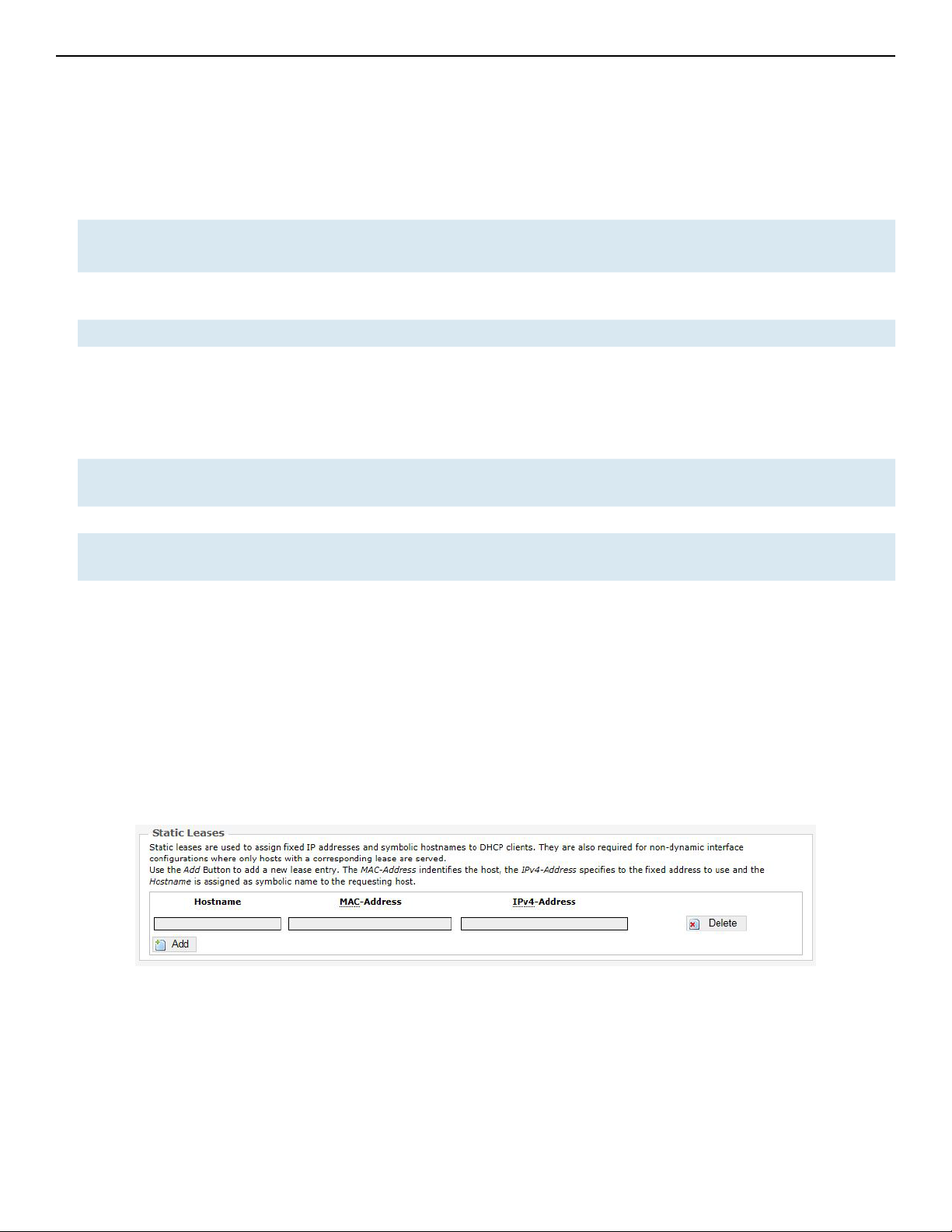
11.2.3 Static Leases
In this section, you can specify that a particular DHCP client obtain an IP address that you define.
The MAC address of the client is required. Click the Add button to add a static DHCP lease, then
click Save & Apply to apply the changes.
Figure 35: Adding a static DHCP lease.
TECH SUPPORT: 1.888.678.9427
INS_NW(1,2)/M_REV– 06/10/13 PAGE 43
Page 44

INSTALLATION AND OPERATION MANUAL NW(1,2)/M
11.3 WiFi – Overview
Clicking on the Network » WiFi tab would bring you to the Wireless Overview page. This page
shows the radios present on the device. These may include the on-board radio and the miniPCI/
miniPCIe radio card.
The wireless local area networks (WLANs) are displayed under each radio.
Figure 36: The Wireless Overview page showing one radio.
Spectrum Shows the Channel Scan Report and allows you to run the Interference Analyzer.
Add Allows you to add virtual access points (VAPs) to the radio. By default, there is only one VAP
on the radio. Each VAP corresponds to one network.
Enable Enables the radio.
Disable Disables the radio.
Edit Brings you to the configuration page of the network. Clicking this button is equivalent to
clicking the corresponding tab above.
TECH SUPPORT: 1.888.678.9427
INS_NW(1,2)/M_REV– 06/10/13 PAGE 44
Page 45

INSTALLATION AND OPERATION MANUAL NW(1,2)/M
11.3.1 Radio in AP Mode
When a radio is operating as an AP, the section for
Associated Stations shows a list of stations connected to this device.
Figure 37: The Associated Stations are also shown on the Wireless Overview page.
The MAC address, network name, received signal strength, noise power, transmit rate, receive
rate, and transmission quality for each station are displayed.
TECH SUPPORT: 1.888.678.9427
INS_NW(1,2)/M_REV– 06/10/13 PAGE 45
Page 46

INSTALLATION AND OPERATION MANUAL NW(1,2)/M
11.3.2 Spectrum: Interference Analyzer
For a radio in AP mode, clicking the Spectrum button would bring up the Channel Scan Report.
Figure 38: The Channel Scan Report.
The button 'Radio 1 View' shows the number of neighboring access points for each channel, the
Min RSSI, Max RSSI, Noise Floor, and Channel Load.
Min RSSI Shows the minimum received signal strength indicator due to the neighboring access
points.
Max RSSI Shows the maximum received signal strength indicator due to the neighboring access
points.
Noise Floor Shows the level of the noise on the channel.
Channel Load Shows how much the channel is utilized. A lower channel load denotes a channel with
less interference.
You can click 'Radio 1 Scan' to do the full channel scan again and get the latest results.
The buttons for Radio 2 would be shown if Radio 2 is enabled on the device.
Return Brings you back to the Wireless Overview page.
TECH SUPPORT: 1.888.678.9427
INS_NW(1,2)/M_REV– 06/10/13 PAGE 46
Page 47

INSTALLATION AND OPERATION MANUAL NW(1,2)/M
11.3.3 Radio in Station Mode
A radio can operate as a Station. This can be set in the Interface Configuration » General Setup »
Mode option, after clicking on the Edit button.
Figure 39: The Wireless Overview page showing a radio as a Client (station).
The following buttons are for a radio operating as a station.
Scan Scans for available wireless networks. This button is available if the device is operating as
a Station. You can then select the network to connect to.
Join Network Associates this device with the selected wireless network.
TECH SUPPORT: 1.888.678.9427
INS_NW(1,2)/M_REV– 06/10/13 PAGE 47
Page 48
INSTALLATION AND OPERATION MANUAL NW(1,2)/M
11.4 WiFi – Wireless Network
As mentioned earlier, clicking on the Edit button for a network would bring you to the configuration
page. This page contains the sections Device Configuration and Interface Configuration.
The Device Configuration section covers the physical settings of the radio hardware such as channel,
transmit power, or antenna selection. These are shared among all defined wireless networks of
the radio. Per network settings like encryption or operation mode are grouped in the Interface
Configuration.
11.4.1 Device Configuration
The Device Configuration section consists of the section tabs for General Setup and Advanced
Settings.
General Setup
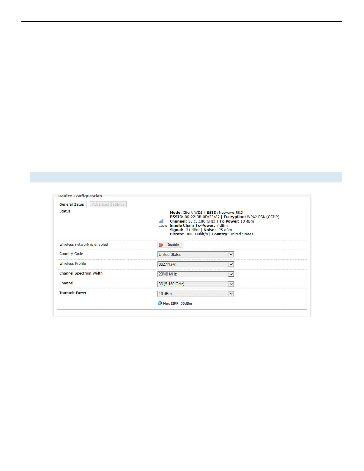
Status Shows a summary of the wireless network.
TECH SUPPORT: 1.888.678.9427
Figure 40: The WiFi Device Configuration section.
INS_NW(1,2)/M_REV– 06/10/13 PAGE 48
Page 49

INSTALLATION AND OPERATION MANUAL NW(1,2)/M
Enable Enables the wireless network.
Disable Disables the wireless network.
Country Code Selects the country. Each country has its own transmit power and frequency regulations.
To ensure regulatory compliance, you must select the country where the device is
operating in. The transmit power levels for each channel are tuned accordingly.
Wireless Profile The default choice of 802.11a+n is a combination of 802.11a and 802.11n, and operates
in the 5 GHz frequency band.
Channel
Spectrum Width
Selects whether 20 MHz or 20/40 MHz bands are used. A 40 MHz band has twice the
throughput of a 20 MHz band. A smaller bandwidth may allow more devices to be
connected. The 20/40 MHz option allows both 20 and 40 MHz bands to be used.
Channel Chooses the frequency channel. The default setting of Auto is may be used. For an AP,
it would select the channel with the least interference from other APs. For a station,
it would automatically select the same channel as its AP. The frequency channel may
also be manually selected. An AP and its station must have the same channel in order
to communicate.
Antenna Gain
(dBi)
Represents the gain relative to an isotropic antenna. A higher antenna gain results in
the transmit power more focused towards a certain direction. When Obey Regulatory
Power is checked, the value of the antenna gain would be taken into account to limit
the selectable transmit power, such that the EIRP limits of the country are satisfied.
Transmit Power
(dBm)
Limits the maximum transmit power of the card at that particular frequency, e.g. 4
dBm, 5 dBm, …, 22 dBm or “Max”. This is the power supplied to the antennas of the
radio. The minimum transmit power values for the radios are:
• For 2-Chain: 4 dBm
The “Max” power depends on both the country and the frequency channel used.
TECH SUPPORT: 1.888.678.9427
INS_NW(1,2)/M_REV– 06/10/13 PAGE 49
Page 50

INSTALLATION AND OPERATION MANUAL NW(1,2)/M
Understanding the Maximum Transmit Power Calculation
The maximum transmit power calculation is illustrated with the following examples.
Example
» Country Code: CZ, Channel = 100
» Antenna Gain is 5dBi
» Transmit Power is 15dBm
In the Czech Republic, Channel = 100 would mean the maximum power is 30dBm for EIRP.
Transmit Power is 15dBm, when adding Antenna Gain of 5dBi, it would be 20dBi, which would
NOT EXCEED the EIRP. Thus the “Max” transmit power of the card is 15dBm, as Antenna Gain
has no effect.
TECH SUPPORT: 1.888.678.9427
INS_NW(1,2)/M_REV– 06/10/13 PAGE 50
Page 51

INSTALLATION AND OPERATION MANUAL NW(1,2)/M
Advanced Settings
Figure 41: Advanced Settings for the Wifi Device Configuration.
Distance
Optimization
(Auto-ACK
Timeout)
Determines the distance of the connected station from the AP and automatically
adjusts the ACK timeout. This is disabled by default. If the stations are positioned
over a wide area at different distances from the AP, it is recommended to disable
this option to prevent the ACK timeout from fluctuating widely.
Distance (meters) Specifies the distance between the AP and the station, if the previous option is
unchecked. Min: 300, Max: 12000 (80MHz), 24000 (40MHz), 48000 (20MHz). This
value may be set to slightly more than the physical distance between the AP and
the farthest station.
Chainmask
Selection
Sets the antenna port selection on the radio. For example, 2x2 means that 2
antennas are being used.
Note: The following options are for the device operating as an access point (AP).
Beacon Interval Specifies the interval between beacon transmissions by the AP, in ms. A beacon is
a frame broadcast by the AP to synchronize the wireless network. For the multiple
VAP case, the beacons are transmitted evenly within this interval. Thus, if four VAPs
are created and the beacon interval is 200 ms, a beacon will be transmitted from
the radio portion every 50 ms, from each VAP in a round-robin fashion. The default
value of the interval is 100 ms.
Adaptive noise
immunity
Controls radio sensitivity in the face of noise sources. Adaptive noise immunity
allows the AP to reject spurs and non-WLAN noise. An advantage is that the AP
would have to spend less time decoding the signal, resulting in lower packet loss
rate.
Dynamic channel
selection
TECH SUPPORT: 1.888.678.9427
Automatically switches channel to avoid interference. Dynamic channel selection
is feature to detect and avoid continuous wave (CW) interference. CW interference
or spurs cause the noise floor to be high. This stops transmissions as well as causes
receives to fail frequently. The noise floor is monitored by the calibration logic.
When the noise floor is above a threshold, the AP is performs an automatic channel
selection. It would disconnect from the stations (it would already have due to the
interference) and move to a new channel. The stations are expected to re-associate
with the AP on their own.
INS_NW(1,2)/M_REV– 06/10/13 PAGE 51
Page 52

INSTALLATION AND OPERATION MANUAL NW(1,2)/M
11.4.2 Interface Configuration
The Interface Configuration section contains the section tabs for General Setup, Wireless Security,
MAC-Filter, and Advanced Settings.
General Setup
Figure 42: The Wifi Interface Configuration section.
Mode Selects whether the device is operating as an Access Point WDS and Station WDS.
Note: Setting more than 1 station on a board is not supported because there can only be
one default gateway. This is true even if a board has both an onboard radio and a card radio.
Both radios cannot be in Station mode at the same time.
ESSID Specifies the name or extended service set identifier (ESSID) of the wireless network as
it is provided in the beacon message. The network name can be up to 32 characters in
length and can contain spaces. When running in AP mode, it is the name of the network as
advertised in the beacon message. In Station mode, it is the network name that the station
associates with.
BSSID Sets the MAC address of the AP. This option is available for a device operating as a station.
This is useful because there can be multiple APs with the same ESSID. Setting the MAC
address would prevent the station from roaming to other APs.
Guard
Interval
Data Rate
(Mbps)
Hide
ESSID
Chooses between Short and Long guard intervals. Guard intervals are used to ensure that
distinct transmissions do not interfere with one another. Data rate is improved in downlink
and uplink if both AP and station use the Short Guard Interval.
Selects the data rate or the modulation and coding scheme (MCS). The default setting of
Auto is recommended. The MCS and data rates are adjusted automatically depending on
the wireless channel conditions.
Hides the network name (ESSID) from being broadcast publicly. (This option is for a device
operating as an AP.)
Note: If the goal is securing your network, use WPA or preferably WPA2 encryption. Hiding
the ESSID does not provide complete security.
TECH SUPPORT: 1.888.678.9427
INS_NW(1,2)/M_REV– 06/10/13 PAGE 52
Page 53

INSTALLATION AND OPERATION MANUAL NW(1,2)/M
WDS
A Wireless Distribution System (WDS) is a system enabling the wireless interconnection of
access points in an IEEE 802.11 network. It allows a wireless network to be expanded using
multiple access points without the traditional requirement for a wired backbone to link them.
The notable advantage of WDS over other solutions is it preserves the MAC addresses of client
frames across links between access points.
WDS may also be considered a repeater mode because it appears to bridge and accept
wireless clients at the same time (unlike traditional bridging).
However, with this method, throughput is halved for all clients connected wirelessly.
Note: WDS Mode is enabled by default.
Wireless Security
Figure 43: Setting the Wireless Security for the Wifi Interface.
Encryption Chooses between No Encryption (open) and the following encryptions: WPA-PSK, WPA2-
PSK, WPAPSK/ WPA2-PSK Mixed Mode, WPA-EAP, and WPA2-EAP.
WPA or WPA2 with PSK
Wifi protected access (WPA) is a stronger encryption than WEP.
Furthermore, WPA2 was developed to strengthen the security of WPA and is stronger than WPA
a nd W E P.
For WPA-PSK, WPA2-PSK, WPA-PSK/WPA2-PSK Mixed Mode encryptions, we have the following
options.
Cipher Can be set to Auto, CCMP (AES), or TKIP and CCMP (AES). The Temporal Key Integrity
Protocol (TKIP) was developed as a temporary replacement for WEP. The Counter Mode
Cipher Block Chaining Message Authentication Code Protocol (CCMP) is based on the
Advanced Encryption Standard (AES) and is the most secure protocol.
Key The pre-shared key (PSK) is the password for the wireless network. This may consist of 8
to 63 ASCII characters.
TECH SUPPORT: 1.888.678.9427
INS_NW(1,2)/M_REV– 06/10/13 PAGE 53
Page 54

INSTALLATION AND OPERATION MANUAL NW(1,2)/M
WPA or WPA2 with EAP
The Extensible Authentication Protocol (EAP) is encapsulated by the IEEE 802.1X authentication
method. IEEE 802.1X is equivalent to EAP over LAN or WLAN. Enterprise networks commonly
use this authentication method.
WPA or WPA2 with EAP (AP Mode)
Figure 44: Encryption options for WPA-EAP or WPA2-EAP in AP mode.
Cipher Can be set to Auto, CCMP (AES), or TKIP and CCMP (AES).
RadiusAuthenticationServer
RadiusAuthenticationPort
RadiusAuthenticationSecret
RadiusAccountingServer
RadiusAccounting-Port
RadiusAccountingSecret
Specifies the IP address of the RADIUS authentication server.
Note: Remote Authentication Dial In User Service (RADIUS) is a networking protocol
that provides centralized Authentication, Authorization, and Accounting (AAA)
management for users that connect and use a network service.
Sets the port number for the RADIUS authentication server. Normally, the port number
is 1812.
Configures the password for the authentication transaction.
Specifies the IP address of the RADIUS accounting server.
Sets the port number for the RADIUS accounting server. Normally, the port number is
1813.
Configures the password for the accounting transaction.
NAS ID Specifies the identity of the network access server (NAS).
TECH SUPPORT: 1.888.678.9427
INS_NW(1,2)/M_REV– 06/10/13 PAGE 54
Page 55
INSTALLATION AND OPERATION MANUAL NW(1,2)/M
WPA or WPA2 with EAP (Station Mode)
Figure 45: Encryption options for WPA-EAP or WPA2-EAP in Station mode.
Cipher Only Cipher option is CCMP (AES)
EAP-Method The authentication protocol can be set to Transport Layer Security (TLS), Tunneled
TLS (TTLS), or Protected EAP (PEAP).
Path to
CA-Certificate
Selects the file for the CA certificate.
Note: The certificate authority (CA) is a trusted third party that issues digital
certificates. In a public key infrastructure scheme, a digital certificate certifies the
ownership of a public key by the named subject of the certificate.
Path to Client-
Selects the file for the client certificate.
Certificate
Options for TLS as the EAP method
Path to Private
Key
Password of
Private Key
Selects the file for the private key.
Configures the password for the private key.
Options for TTLS or PEAP as the EAP method
Authentication Selects the authentication method used by the AP, e.g. PAP, CHAP, MSCHAP, or
MSCHAPV2.
Identity Sets the identity used by the supplicant for EAP authentication.
Password Sets the password used by the supplicant for EAP authentication.
TECH SUPPORT: 1.888.678.9427
INS_NW(1,2)/M_REV– 06/10/13 PAGE 55
Page 56

INSTALLATION AND OPERATION MANUAL NW(1,2)/M
MAC-Filter
This section tab is only available for a device operating as an AP.
Figure 46: Configuring the MAC-Filter for a Wifi AP.
MAC-Address
Filter
Lets you allow only devices with the listed MAC address to associate with this AP, or lets
you block devices with the listed MAC address.
MAC-List Adds the MAC address of the remote device to either block or allow.
TECH SUPPORT: 1.888.678.9427
INS_NW(1,2)/M_REV– 06/10/13 PAGE 56
Page 57

INSTALLATION AND OPERATION MANUAL NW(1,2)/M
Advanced Settings
Figure 47: Advanced Settings for the Wifi Interface.
RTS Threshold Sets the threshold for the packet size above which the request to send (RTS) mechanism
is used. The default is 2346 octets.
There is a trade-off to consider when setting this parameter. On the one hand, using a
small value causes RTS packets to be sent more often, consuming more of the available
bandwidth, and therefore reducing the throughput of the network packet. On the other
hand, when more RTS packets are sent, the system recovers faster from interference
or collisions. This is useful in a heavily loaded network, or a wireless network with high
electromagnetic interference.
Note: The following options for Station Isolation, Maximum Stations, Minimum Stations
RSSI, and 802.11n only are available only for a device operating as an AP.
Station
Isolation
Prevents station-to-station communication, unchecked by default. When Station
Isolation is disabled, wireless clients can communicate with one another normally
by sending traffic through the AP. When Station Isolation is enabled, the AP blocks
communication between wireless clients on the same AP.
Maximum
Specifies the maximum number of associated stations, the default being 127.
Stations
Minimum
Stations RSSI
Sets the minimum received signal strength indicator for a station to be associated. The
default value of 0 means that the AP would allow a station to associate independent of
its RSSI.
80 2.11n O nl y Forces the device to use only the IEEE802.11n standard, unchecked by default.
HT 20/40
Coexistence
Allows the network to use both 20 MHz and 40 MHz bands. Required on AP side
primarily to support co-existence. The station can also send intolerant bit status to AP
to signal use of 20 MHz channel. The station will follow the AP's channel bonding and
channel switching HT 20/40 mechanism. Disabling this setting forces the use of 40 MHz
bandwidth/channel bonding, and results in high data rate.
WMM Provides Quality of Service (QoS) features, checked by default. Wireless multimedia
enables the classification of the network traffic into 4 main types, voice, video, best
effort, and background, in decreasing order of priority. Higher priority traffic has a
higher transmission opportunity and would have to wait less time to transmit. As a
result, an existing video stream would not be interrupted by additional background
processes.
TECH SUPPORT: 1.888.678.9427
INS_NW(1,2)/M_REV– 06/10/13 PAGE 57
Page 58
INSTALLATION AND OPERATION MANUAL NW(1,2)/M
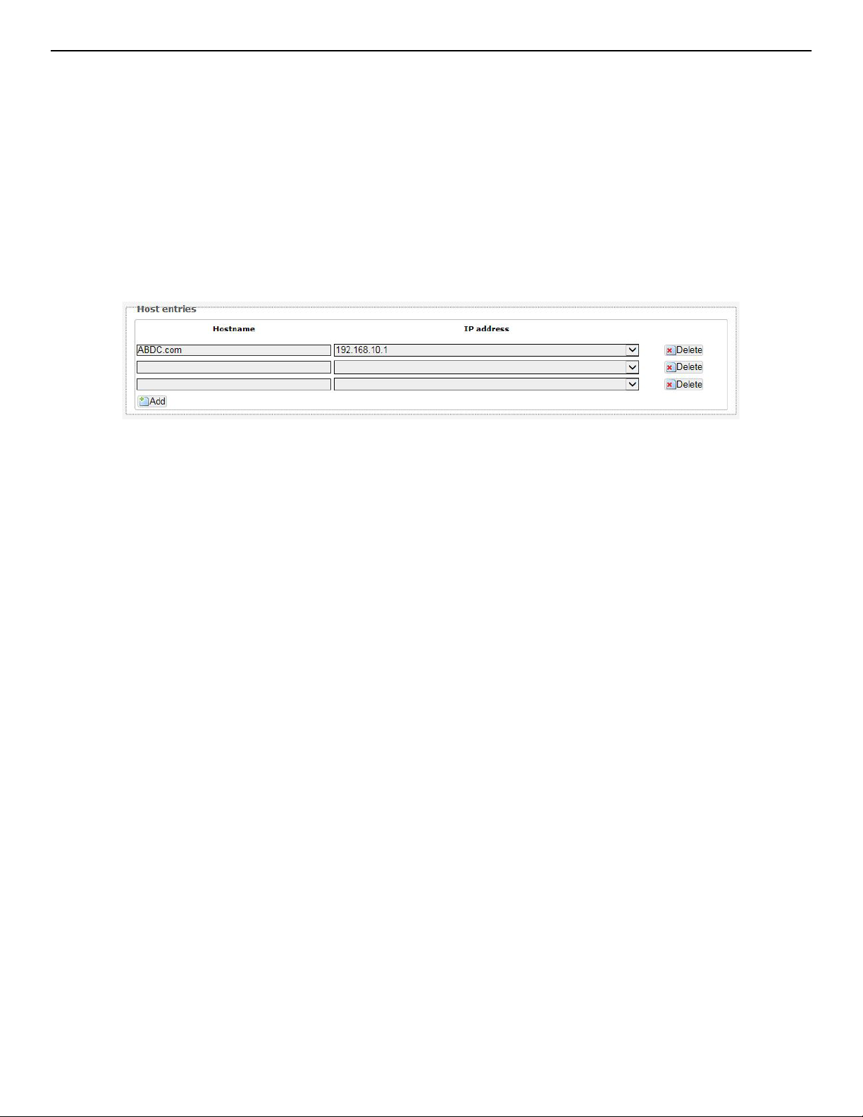
11.5 Hostnames
In the Network » Hostnames page, you can specify custom hostnames (URLs) with their respective
IP addresses. This is an additional local DNS.
Note: The computers in the same subnet need to set the IP address of this device as their
preferred DNS server in order to interpret these custom hostnames.
11.6 Static Routes
The Network » Static Routes page shows the static IPv4 routes.
Figure 48: Static IPv4 Routes.
Each row shows the interface and gateway over which a certain host or network can be reached.
TECH SUPPORT: 1.888.678.9427
INS_NW(1,2)/M_REV– 06/10/13 PAGE 58
Page 59
INSTALLATION AND OPERATION MANUAL NW(1,2)/M
11.7 Firewall
The Network » Firewall page contains the subpages for General Settings, Port Forwards, and
Traf fic Rule s.
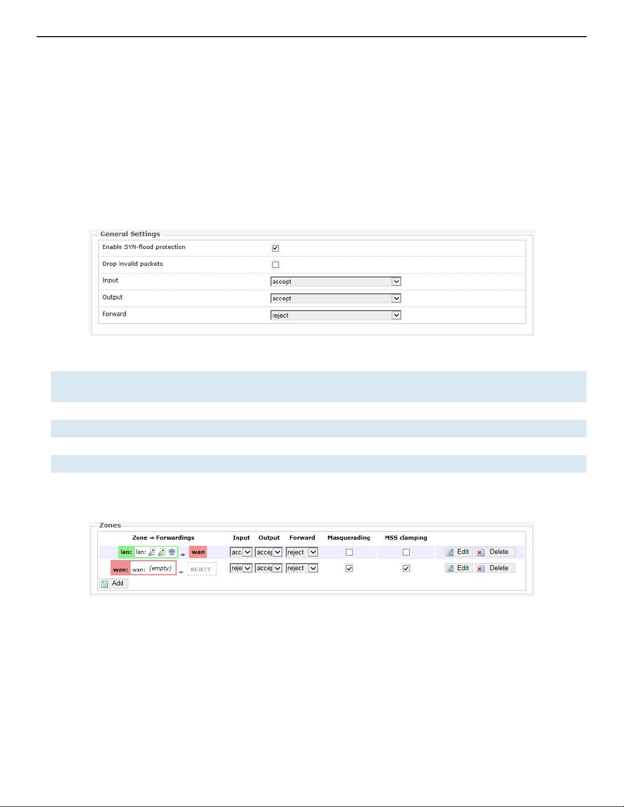
11.7.1 General Settings
The firewall creates zones over the network interfaces to control network traffic flow.
The Network » Firewall » General Settings page contains the zone settings.
Zone Settings
Figure 49: General Settings for the Firewall Zones.
Enable SYN-flood
protection
Drop invalid packets Unchecked by default.
Input To accept by default.
Output To accept by default.
Forward To reject by default.
Checked by default.
Zones
Figure 50: The Zones section showing the default settings for the firewall zones.
11.7.2 Port Forwards
Port forwarding allows remote computers on the Internet to connect to a specific computer or
service within the private LAN.
The Network » Firewall » Port Forwards page lets you define the protocol and port number to
access an internal IP address.
TECH SUPPORT: 1.888.678.9427
INS_NW(1,2)/M_REV– 06/10/13 PAGE 59
Page 60

INSTALLATION AND OPERATION MANUAL NW(1,2)/M
Figure 51: Adding a port forwarding rule.
11.7.3 Traffic Rules
The Network » Firewall » Traffic Rules page configures the traffic rules and source NAT.
Traf fic Rules
Traffic rules define policies for packets travelling between different zones, for example to reject
traffic between certain hosts or to open WAN ports on the router.
Figure 53: You can choose to open ports on the router or add new forwarding rules.
TECH SUPPORT: 1.888.678.9427
Figure 52: Firewall Traffic Rules with the default settings.
INS_NW(1,2)/M_REV– 06/10/13 PAGE 60
Page 61

INSTALLATION AND OPERATION MANUAL NW(1,2)/M
Source NAT
Source NAT is a specific form of masquerading which allows fine grained control over the
source IP used for outgoing traffic, for example to map multiple WAN addresses to internal
subnets.
Figure 54: Source NAT.
11.8 Diagnostics
11.8.1 Network Utilities
Figure 55: Network Utilities consist of Ping, Traceroute, and Nslookup.
Figure 56: Result of Ping.
Figure 57: Result of Traceroute.
TECH SUPPORT: 1.888.678.9427
Figure 58: Result of Nslookup.
INS_NW(1,2)/M_REV– 06/10/13 PAGE 61
Page 62
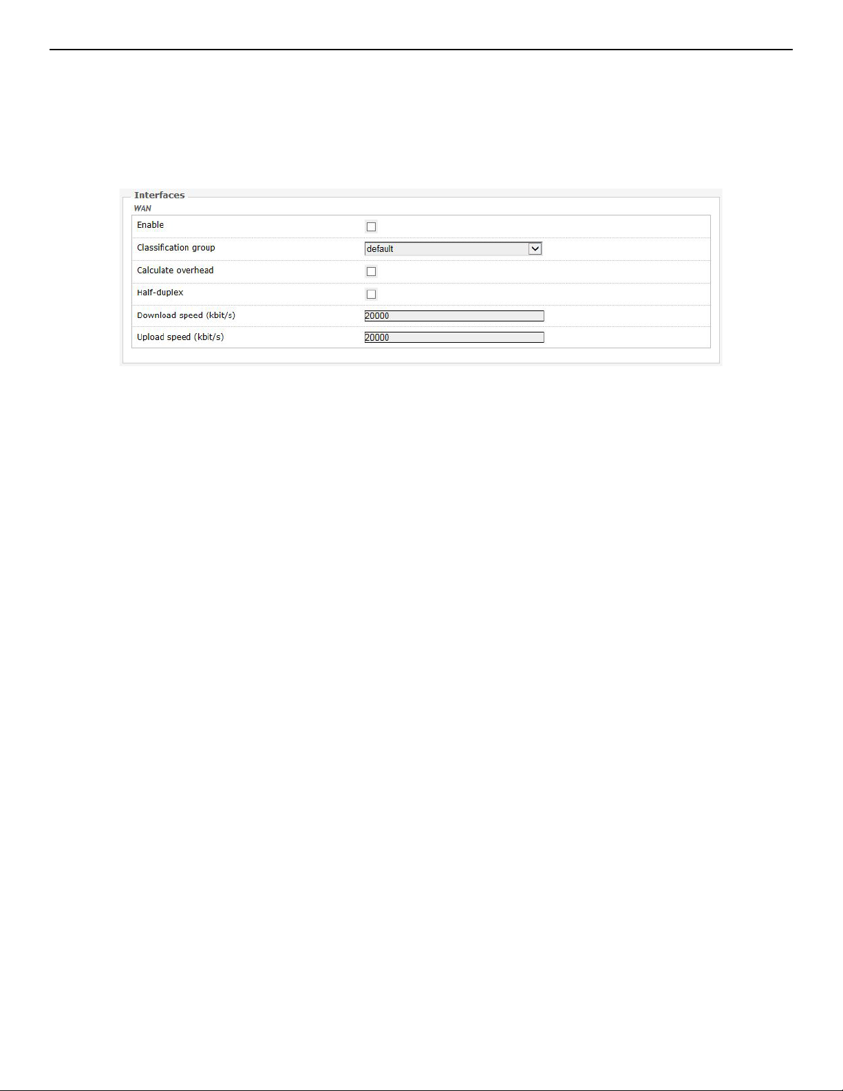
INSTALLATION AND OPERATION MANUAL NW(1,2)/M
11.9 Quality of Service
The Network » QoS page configures the quality of service (QoS). With QoS you can prioritize
network traffic that passes through the WAN port. You can limit the download and upload speeds.
Network QoS is disabled by default.
Figure 59: Network QoS settings.
TECH SUPPORT: 1.888.678.9427
INS_NW(1,2)/M_REV– 06/10/13 PAGE 62
Page 63

INSTALLATION AND OPERATION MANUAL NW(1,2)/M
12.0 AP Controller Tab
APs running the Netwave OpenWRT firmware can be managed by an Access Point Controller
(APc). The APc sends and receives information from Comnet OpenWRT APs using the SNMPv3
protocol.
12.1 Getting Started with Managing APs using the APc
For each AP, please perform the following steps in the AP's web page:
1. Set the APc IP address.
2. Set the AP's IP address, default gateway, and custom DNS server.
» The web page may not jump automatically to the new IP address if the subnet changed, so
please re-enter the new IP address in the browser.
» Click on the network tab to check that the L2TP is communicating packets with the APc.
3. Set the hostname of the AP to better identify it.
The following describes the “APController” top-level tab.
When using the APc for the first time, you only need to set the IP address of the APc. This has to
be done in the AP's configuration web page itself. All other settings should remain as the default
values for now.
Please always click “Save & Apply”. Do not click “Save”. This is to apply the settings immediately.
12.2 L2TPv3 Settings
The following are the settings for the Layer 2 Tunneling Protocol Version 3 (L2TPv3).
Remote Server Configures the IP address of the APc e.g. 192.168.3.178.
Chap-username Sets the username for the Challenge-Handshake Authentication Protocol (CHAP).
Chap-secret Sets the password for the Challenge-Handshake Authentication Protocol (CHAP).
TECH SUPPORT: 1.888.678.9427
INS_NW(1,2)/M_REV– 06/10/13 PAGE 63
Page 64
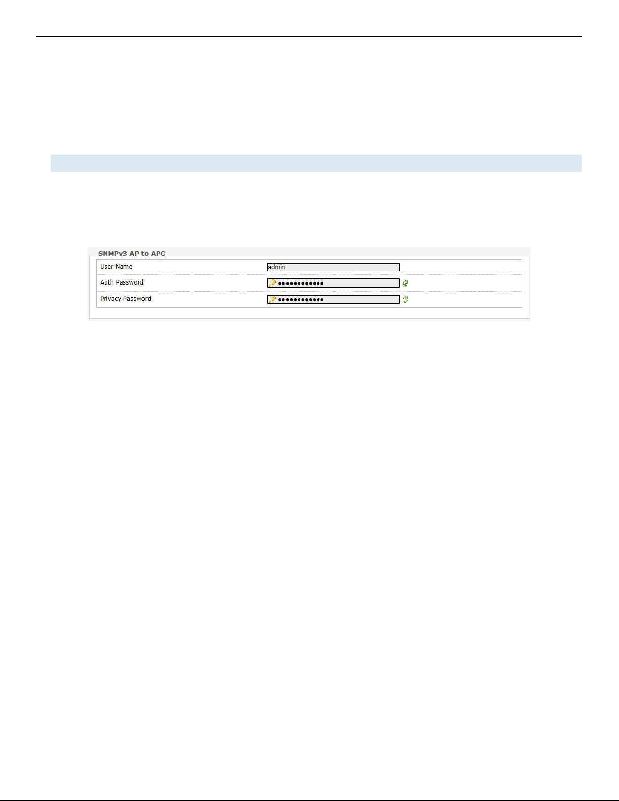
INSTALLATION AND OPERATION MANUAL NW(1,2)/M
12.3 IPSec
By default, the Internet Protocol Security (IPsec) is disabled for the Netwave Radio boards to
decrease the usage of the CPU resources. It can also be enabled.
The L2TPv3 itself already provides data channel protection against malicious data insertion.
Pre-shared key Sets the password for the IPsec.
12.4 APc SNMP Settings
The “SNMPv3 AP to APC” section contains the APc SNMP settings.
Figure 60: APc SNMP Settings.
Currently, the following default values must be used.
User Name: “admin”
Auth Password: “apc0ntr0ll3r”
Privacy Password: “apc0ntr0ll3r”
12.5 AP SNMP Settings
For communication from the APc to the AP, the settings in the following section of the LuCI web
page is used:
System » SNMP » SNMP Configuration » General Settings
The description of the SNMP options are mentioned in Section "SNMP Configuration."
TECH SUPPORT: 1.888.678.9427
INS_NW(1,2)/M_REV– 06/10/13 PAGE 64
Page 65

INSTALLATION AND OPERATION MANUAL NW(1,2)/M
13.0 Troubleshooting
13.1 Troubleshooting steps
13.1.1 PC cannot connect to the router
The configuration web page for the router would not be able to show up if the router and your
computer are not connected. If the PC and the router are joined to the network by LAN cables,
they would not be able to connect if any of the network cable connections are loose. A possible
indicator is that there is no light at the LAN port of the PC. In Windows, if you click the network
icon and click to “View network connections”, the LAN port shows “Disconnected”. Please ensure
that all the connections are tight. Sometimes, disconnecting and reconnecting the LAN cable
solves connection problems if DHCP is used, because the DHCP server and DNS server are reset.
(Also, dis-associating and re-associating to the wireless network has a similar benefit as
unplugging and re-inserting the LAN cable.)
The router, the computer, and the gateway must have IP addresses on the same network. For
example, if you use a subnet mask of 255.255.255.0 and the gateway IP address is 192.168.3.1, all
the IP addresses must be unique and be of the form 192.168.3.X. Check whether the router and
your computer are connected on the same network by running the ping command to ping the IP
address of the router.
Alternatively, type the following in the router's Linux terminal:
• ping 192.168.3.77 (if your computer's IP address is 192.168.3.77 for example.)
They should be able to give the ping responses.
An IP address conflict would cause unstable pings.
Switch to another address and ping the conflicting address to check.
If using a Windows computer, you should run the command arp -d * if the network configuration
has changed. This is to delete the address resolution protocol (ARP) table in Windows as it may
not update fast enough.
If the ping still cannot get responses, try disabling the firewall on your Windows computer. The
Windows Firewall on your computer may prevent it from sending back a ping response. Disabling the
firewall may be a security risk, so you should take the precaution of disconnecting the Internet first.
13.1.2 PC Ethernet and Wifi adapters
If your PC has both Ethernet and Wifi adapters, they must not have the same subnet. Otherwise,
packets from the PC may not be directed to the correct network.
13.2 Resetting to factory default
To reset the router to the factory default settings, while the power is on, hold down the reset
button for 8 seconds and then release
TECH SUPPORT: 1.888.678.9427
INS_NW(1,2)/M_REV– 06/10/13 PAGE 65
Page 66

INSTALLATION AND OPERATION MANUAL NW(1,2)/M
14.0 Glossary
Term Definition
Access Point (AP) A device that provides network access to associated stations (connected wireless
devices). A wireless router can function as an AP.
ACK Acknowledgment. This is a response to a transmission to indicate that the data
packet was received correctly.
ARP Address Resolution Protocol. This is a broadcast protocol for mapping IP
addresses to MAC addresses.
CHAP Challenge-Handshake Authentication Protocol. This is a protocol for
authenticating users to an ISP.
CPE Customer-Premises Equipment. This is also known as a station.
dB Decibels. This is a measure of intensity.
dBm Decibel-milliwatts. This is a measure of power relative to 1 mW. This is commonly
used to measure wireless signal power. A higher power leads to better signal
quality.
DDNS Dynamic DNS. This is a system for updating domain names in real time. It allows a
domain name to be assigned to a device with a dynamic IP address.
DHCP Dynamic Host Configuration Protocol. This is a protocol for allocating IP addresses
dynamically so that addresses can be reused when hosts (e.g. computers) no
longer need them.
DNS Domain Name System. This is a distributed and hierarchical naming system
for computers, services, or any resource connected to the Internet or a private
network.
EIRP Equivalent Isotropically Radiated Power. Each country sets the legally permitted
maximum for the EIRP limits on each channel.
ESSID Extended Service Set Identifier. This is the name of the wireless network. It is case-
sensitive and up to 32 alphanumeric characters in length. The ESSID differentiates
one wireless network from another. All access points and devices trying to
connect to a specific wireless network should use the same ESSID (and password)
to enable effective roaming.
FTP File Transfer Protocol. This is a protocol for transferring files between network
nodes.
HTTP Hypertext Transfer Protocol. This is a protocol used by web browsers and web
servers to transfer files.
IP Internet Protocol. This is the primary communications protocol used for relaying
network packets (also known as datagrams) across an internetwork using the
Internet Protocol Suite. IP is responsible for routing packets across network
boundaries. It is the principle protocol that establishes the Internet.
ISP Internet Service Provider.
L2TP Layer 2 Tunneling Protocol. This is a tunneling protocol used to support virtual
private networks (VPNs) or as part of the delivery of services by ISPs. It does not
provide any encryption or confidentiality by itself. Rather, it relies on an encryption
protocol that it passes within the tunnel to provide privacy.
LAN Local Area Network.
TECH SUPPORT: 1.888.678.9427
INS_NW(1,2)/M_REV– 06/10/13 PAGE 66
Page 67

INSTALLATION AND OPERATION MANUAL NW(1,2)/M
Term Definition
Layer 2 Data link layer of the Open Systems Interconnection (OSI) model. This corresponds to
the Link layer of the Internet protocol suite.
MAC Address Media Access Control Address. This is a globally unique identifier attached to a
network adapter. It also identifies the hardware manufacturer.
Mbps Megabits per second. Also Mbit/s. This is a measure of the data rate.
MiniPCIe Mini Peripheral Component Interconnect Express. A miniPCIe radio is a radio card
that can be inserted into a router's circuit board.
MTU Maximum transmission unit. This is the size, in bytes, of the largest packet that can
be passed on. The MTU for Ethernet is a 1500-byte packet.
NAT Network Address Translation. This is the process of rewriting IP addresses as a
packet passes through a controller or firewall. NAT enables multiple computers
(or hosts) on a LAN to access the Internet using the single public IP address of the
LAN's gateway controller.
NMS Network Management Station. This is a software which runs on the SNMP
manager. It is sometimes simply referred to as an SNMP manager.
NTP Network Time Protocol. This is a protocol for synchronizing a controller to a single
clock on the network, known as the clock master.
PAP Password Authentication Protocol. This is a protocol for authenticating users to a
remote access server or ISP.
PPPoE Point-to-Point Protocol over Ethernet. This is a protocol for connecting a network
of hosts to an ISP without the ISP having to manage the allocation of IP addresses.
PPTP Point-to-Point Tunneling Protocol. This is a protocol for the creation of VPNs for the
secure transfer of data from remote clients to private servers over the Internet.
QoS Quality of Service. This is the prioritization of network traffic. Voice traffic gets
the highest priority, followed by video, best effort, and background traffic, in this
order.
RADIUS Remote Authentication Dial In User Service. This is a networking protocol that
provides Authentication, Authorization, and Accounting (AAA) management for
remote users. The RADIUS provides centralized management of usernames and
passwords.
SNMP Simple Network Management Protocol. This is an Internet-standard protocol for
managing devices on IP networks. It consists of a set of standards for network
management, including an application layer protocol, a database schema, and a
set of data objects. SNMP exposes management data in the form of variables on
the managed systems, which describe the system configuration. These variables
can then be queried (and sometimes set) by managing applications.
SSID Service Set Identifier. This is also known as the ESSID or the wireless network
name.
Station A device that connects wirelessly to an access point.
Subnet A portion of a network that shares a common address component. On TCP/IP
networks, subnets are defined as all devices whose IP addresses have the same
prefix. For example, all devices with IP addresses that start with 192.168.10 belong
to the same subnet.
TCP Transmission Control Protocol. This is a protocol for transmitting data over the
Internet with guaranteed reliability and in-order delivery.
TECH SUPPORT: 1.888.678.9427
INS_NW(1,2)/M_REV– 06/10/13 PAGE 67
Page 68

INSTALLATION AND OPERATION MANUAL NW(1,2)/M
Term Definition
UDP User Datagram Protocol. This is a protocol for transmitting data over the Internet
quickly but with no guarantee of reliability or in-order delivery.
VAP Virtual Access Point. A VAP simulates a physical access point. A VAP is configured
on a per-radio basis. By default, only one VAP is enabled. Up to 16 VAPs can be
created for each radio, each with its own SSID.
VPN Virtual Private Network. This is a network that enables IP traffic to travel securely
over a public TCP/IP network by encrypting all traffic from one network to another.
The VPN uses tunneling to encrypt all information at the IP level.
WAN Wide Area Network. This is a network that covers a broad area. The world's most
popular WAN is the Internet.
Web Browser A software that allows the user to surf the Internet.
WDS Wireless Distribution System. This is a system enabling the wireless
interconnection of access points in an IEEE 802.11 network. It allows a wireless
network to be expanded using multiple access points without the traditional
requirement for a wired backbone to link them.
WLAN Wireless Local Area Network.
TECH SUPPORT: 1.888.678.9427
INS_NW(1,2)/M_REV– 06/10/13 PAGE 68
Page 69

INSTALLATION AND OPERATION MANUAL NW(1,2)/M
15.0 Agency Compliance
FCC
Changes or modifications not expressly approved by the party responsible for compliance
could void the user’s authority to operate the equipment. This device complies with Part 15 of
the FCC Rules. Operation is subject to the following two conditions:
• This device may not cause harmful interference, and
• This device must accept any interference received, including interference that may cause
undesired operation.
This equipment has been tested and found to comply with the limits for a Class A digital
device, pursuant to part 15 of the FCC Rules. These limits are designed to provide reasonable
protection against harmful interference when the equipment is operated in a Industrial
environment. This equipment generates, uses, and can radiate radio frequency energy
and, if not installed and used in accordance with the instruction manual, may cause harmful
interference to radio communications. Operations of this equipment in a residential area is likely
to cause harmful interference in which case the user will be required to correct the interference
at his own expense.
Industry Canada
This Class A digital apparatus complies with Canadian ICES-003. To reduce potential radio
interference to other users, the antenna type and its gain should be so chosen that the
equivalent isotropically radiated power (EIRP) is not more than that permitted for successful
communication. This device complies with Industry Canada license-exempt RSS standard(s).
Operation is subject to the following two conditions:
• This device may not cause interference, and
• This device must accept any interference, including interference that may cause undesired
operation of the device.
Cet appareil numérique de la classe A est confrome à la norme NMB-003 Canada. Pour réduire
le risque d’interférence aux autres utilisateurs, le type d’antenne et son gain doivent être
choisies de façon que la puissance isotrope rayonnée équivalente (PIRE) ne dépasse pas ce qui
est nécessaire
pour une communication réussie. Cet appareil est conforme à la norme RSS Industrie Canada
exempts de licence norme(s). Son fonctionnement est soumis aux deux conditions suivantes:
17 Compliance
• Cet appareil ne peut pas provoquer d’interférences et
• Cet appareil doit accepter toute interférence, y compris les interférences qui peuvent
causer un mauvais fonctionnement du dispositif.
TECH SUPPORT: 1.888.678.9427
INS_NW(1,2)/M_REV– 06/10/13 PAGE 69
Page 70

INSTALLATION AND OPERATION MANUAL NW(1,2)/M
RF Exposure Warning
The antennas used for this transmitter must be installed to provide a separation distance of at
least 2.52m from all persons and must not be located or operating in conjunction with any other
antenna or transmitter.
Les antennes utilisées pour ce transmetteur doivent être installé en considérant une distance
de séparation de toute personnes d'au moins 2.52m et ne doivent pas être localisé ou utilisé en
conflit avec tout autre antenne ou transmetteur.
CE Marking
CE marking on this product represents the product is in compliance with all directives that are
applicable to it.
This equipment may be operated in the following countries:
Great Britain and Northern Ireland, Austria, Belgium, Denmark, Finland, France, Germany,
Ireland, Italy, Netherlands, Norway, Portugal, Romania, Switzerland, Sweden
Installer Compliance Responsibility
Devices must be professionally installed and it is the professional installer's responsibility to
make sure the device is operated within local country regulatory requirements.
RoHS/WEEE Compliance Statement
European Directive 2002/96/EC requires that the equipment bearing this symbol on the
product and/or its packaging must not be disposed of with unsorted municipal waste. The
symbol indicates that this product should be disposed of separately from regular household
waste streams. It is your responsibility to dispose of this and other electric and electronic
equipment via designated collection facilities appointed by the government or local authorities.
Correct disposal and recycling will help prevent potential negative consequences to the
environment and human health. For more detailed information about the disposal of your old
equipment, please contact your local authorities, waste disposal service, or the shop where you
purchased the product.
TECH SUPPORT: 1.888.678.9427
INS_NW(1,2)/M_REV– 06/10/13 PAGE 70
Page 71

INSTALLATION AND OPERATION MANUAL NW(1,2)/M
16.0 GPL (General Public License) Statement
You may have received from ComNet products that contained – in part – free software (software
licensed in a way that ensures your freedom to run, copy, distribute, study, change and improve
the software). Such products include NetWave series of products.
As part of these products, ComNet may have distributed to you hardware and/or software that
contained a version of free software programs developed by the Free Software Foundation, a
separate not-for-profit organization without any affiliation to ComNet.
See http://www.gnu.org/philosophy/free-sw.html for more details. If ComNet distributed any
portions of these free software programs to you, you were granted a license to that software
under the terms of either the GNU General Public License or GNU Lesser General Public
License “License”, copies of which are available from http://www.gnu.org/licenses/licenses.html.
The Licenses allow you to freely copy, modify and redistribute that software without any other
statement or documentation from us.
ComNet will provide to anyone who contacts us at the contact provided below, for a charge of
no more than our cost of physically performing source code distribution, a complete machinereadable copy of the complete corresponding source code for the free software programs used
in the version of the programs that we distribute to you. The cost will be free if the delivery
medium of the machine-readable copy is through the Internet.
Contact information:
Email: techsupport@comnet.net
Tel: 203-796-5300
Address: 3 Corporate Drive, Danbury, CT 06810 USA
We will reply within 7 working days once the request has been made through email or telephone.
TECH SUPPORT: 1.888.678.9427
INS_NW(1,2)/M_REV– 06/10/13 PAGE 71
Page 72

INSTALLATION AND OPERATION MANUAL NW(1,2)/M
ComNet Customer Service
Customer Care is ComNet Technology’s global service center, where
our professional staff is ready to answer your questions at any time.
Email ComNet Global Service Center: customercare@comnet.net
Contact Information
ComNet – www.comnet.net
Te l: +1- 203 -7 96 - 53 00
North America
EMEA, PACRIM,
South America
ComNet Corporate Headquarters
and Customer Support Center
ComNet Europe Ltd, Leeds
Tel: +1-888-6789427
Email: info@comnet.net
Tel: +44 (0)113 307 6400
Tel: +44 (0)113 307 6409
Email: info-europe@comnet.net
3 CORPORATE DRIVE | DANBURY, CT 06810 | USA
T: 203.796.5300 | F: 203.796.5303 | TECH SUPPORT: 1.888.678.9427 | INFO@COMNET.NET
8 TURNBERRY PARK ROAD | GILDERSOME | MORLEY | LEEDS, UK LS27 7LE
T: +44 (0)113 307 6400 | F: +44 (0)113 253 7462 | INFO-EUROPE@COMNET.NET
© 2015 Communications Ne tworks Cor poration. All Rights Reser ved. “ComNet” and the “ComNet Logo” are registered trademarks of Communication Net works, LLC .
TECH SUPPORT: 1.888.678.9427
INS_NW(1,2)/M_REV– 06/10/13 PAGE 72
 Loading...