

Page 1
QUICK START GUIDE
INDUSTRIAL OUTDOOR HIGH THROUGHPUT
802.11A/N WIRELESS ETHERNET
This manual serves the following
ComNet Model Numbers:
NW10
NW10E
Thank you for purchasing NetWave® from ComNet. This quick start guide is designed to
walk you through installation.
This guide applies to the following models:
NW10: Industrial Multipoint, FCC Version, User Configurable
NW10E: Industrial Multipoint, ETSI Version, User Configurable
An easy to read LED array displays unit operational status along with received signal
strength ensuring optimal installation and operation. See Figure 2 on Page 2 for LED
Indicator explanations.
See Figures 3 through 5 beginning on Page 3 for mounting instructions.
INS_NW10_NW10E_QS_REV– 07/7/15 PAGE 1
Page 2
QUICK START USER GUIDE NW10[E]
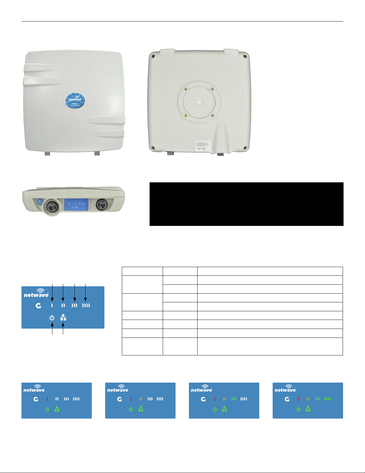
FIGURE 1 – INDUSTRIAL HIGHTHROUGHPUT WIRELESS ETHERNET LINK
PORT 1 - POE IN PORT 2 - POE OUT
BOTTOM
FIGURE 2 – STATUS INDICATING LEDS
LED VISUAL CUE INDICATION
RSSI1POWER
RSSI2POrt 2 LAN
RSSI3
RSSI4
POWER
LAN
RSSI1 SOLID RED Weak Connection
RSSI2 SOLID ORANGE Moderate Connection
RSSI3 SOLID GREEN Solid Connection
RSSI4 SOLID GREEN
PORT 1 - POE INPORT 2 - POE OUT
BACKFRONT
IMPORTANT: Only plug PoE power to Port 1.
Connecting a PoE power source to the PSE Port (#2) will
cause a major device malfunction and void the warranty.
SOLID GREEN Power is supplied to the unit
OFF No power is supplied to the unit, or the unit is in reset.
SOLID GREEN LAN Connected
OFF No Connectivity
Excellent Connection
(Advisable to check Status Page to confirm RSSI is > -55)
SIGNAL STRENGTH:
WEAK SIGNAL EXCELLENT SIGNAL
TECH SUPPORT: 1.888.678.9427
INS_NW10_NW10E_QS_REV– 07/7/15 PAGE 2
Page 3
QUICK START USER GUIDE NW10[E]
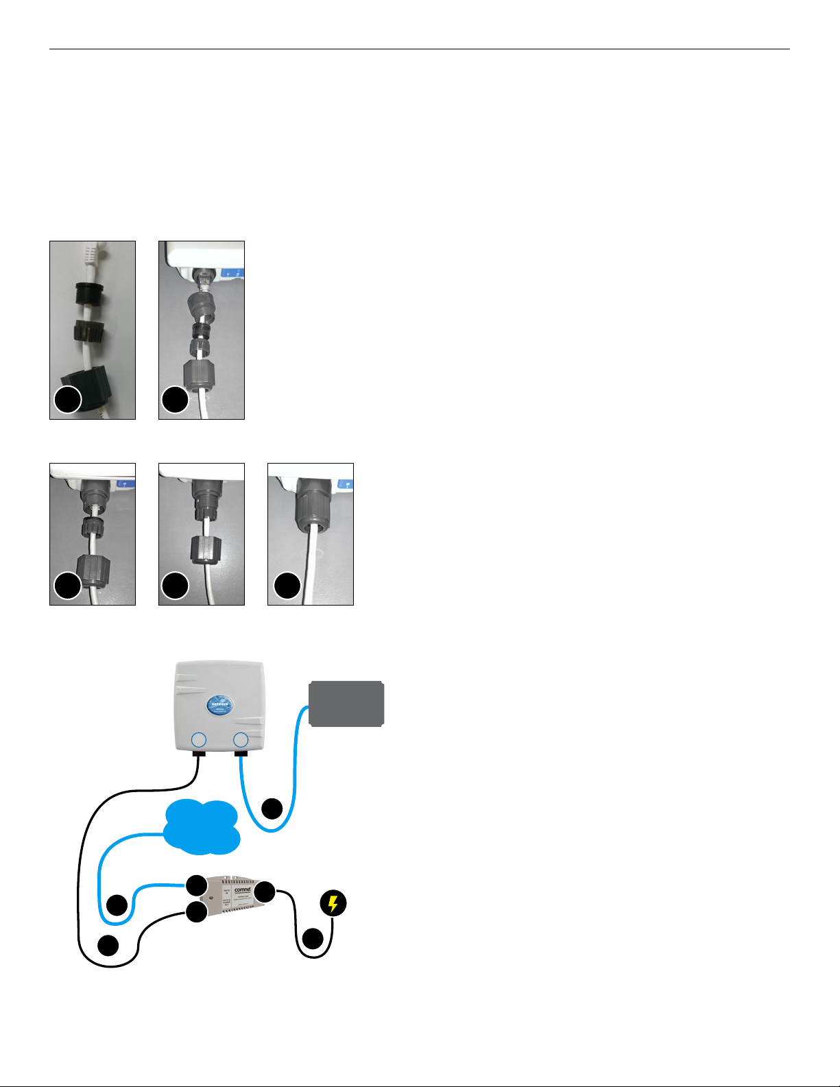
FIGURE 3 – INSTALLATION INSTRUCTIONS
Step 1.
Unpack the mounting hardware from the box. Determine if this will be a pole or wall mount application.
The included Mounting kit is designed to support poles up to 2 in (5.8 cm) in diameter. If surface or wall mounting, the optional
NWBKT hardware will be required.
Step 2.
A. Route the RJ45 connectorized Ethernet cable through the
weather tight gland connection as shown at left.
Note: The slit rubber washer allows a pre-terminated
Ethernet cable to be used.
Once the cable has been routed through the weather
connection as shown above, push the split rubber gasket
into place and loosely screw the cap that goes over the
rubber washer.
A
B
B. Snap the RJ-45 connector in place as shown
Step 3.
Slide the weather proof assembly over the cable so it can be
screwed into the enclosure gland. Make sure the rubber sealing
ring is in place as shown in step 3A.
Tighten the weather proof assembly into the enclosure and also
tighten the cap that squeezes the rubber washer over the Ethernet
A
B C
Network
Edge Device
P1 P2
Ethernet
D
Network
B
D
A
D
C
D
cable as shown.
Step 4.
A. Connect one end of an RJ-45 Ethernet cable to the OUT
port of the CNGE1IPS or other 35W PoE Injector (sold
separately) and the other end to LAN of the access point.
Maximum length of the RJ-45 CAT5 cable is 100 meters.*
B. Connect the RJ-45 Ethernet cable attached to the PoE
Injector to a network device, such as to a switch or to the PC
you will use to configure the access point.
C. Connect the power adaptor to the main electrical supply
and the power plug into the socket of the PoE Injector .
PoE power input: Passive PoE (range 36 to 48 VDC).
The NW10[E] can also be powered by a suitable IEEE
802.3af/at PSE device such as a PoE switch or injector.
D. A Drip Loop is recommended as additional precaution
against moisture entering the Access Point housing.
TECH SUPPORT: 1.888.678.9427
* Up to 200mW radio. For higher power radio upgrade to higher rating
power adapter.
INS_NW10_NW10E_QS_REV– 07/7/15 PAGE 3
Page 4

QUICK START USER GUIDE NW10[E]
FIGURE 4 – POLE MOUNT INSTRUCTIONS
Included Hardware
Vertical Mount in -45º Position Vertical Mount in +45º Position
TECH SUPPORT: 1.888.678.9427
INS_NW10_NW10E_QS_REV– 07/7/15 PAGE 4
Page 5

QUICK START USER GUIDE NW10[E]
INSTALLATION REQUIREMENTS
Shielded outdoor CAT 5 or better should be used for all out of plant Ethernet connection and should be properly grounded
through the PoE AC ground. Industrial grade shielded Ethernet cable is recommended to help prevent ESD damage commonly
experienced with outdoor installations. Visit www.comnet.net/comnet-products/cables
CONFIGURING NETWAVE
1. Connect an Ethernet cable from the port labelled as IN on the power Injection Module to either a laptop or a PC LAN port.
2. Connect the second Ethernet cable from the OUT port on the Power Injection Module to the NetWave LAN port.
3. Apply 48 VDC to the Power Injection Module with the provided power supply. You should notice the green LED illuminate in
the Power Injection Module and the power LED on the NetWave unit.
4. Set the IP address of the laptop being used to configure NetWave to static and the subnet to 192.168.10.x/24 subnet.
5. Point the browser to 192.168.10.101. This is the default address.
6. A login prompt will pop up. Enter:
ID: admin
Password: admin
7. Select the NETWORK » Interfaces tab, click on Edit in the LAN settings section to change the IP address of the device. and set
the desired network settings.
• Hit Save & Apply
NOTE: This will be the network address for the NetWave web server. It is not necessary to set to the same subnet as the
operating network but it is recommended.
8. Select the NETWORK -> WIFI tab and set:
• Wireless mode – Set to AP or Client
• Country code – Only required if setting up the NW10E and NWK7E/M (ETSI) models
NOTE: It is the user’s responsibility to ensure that the correct country is chosen. ComNet accepts no liability for incorrectly set
up equipment.
• Output RF power – if RSSI is greater than -40, it is recommended to reduce RF TX power at the connected remote node.
• Set SSID – if changing from the default setting
• Channel Spectrum Width – May want to reduce to 20M from the default 20/40M if the 5GHz spectrum is crowded or
connections across the link are unstable.
• Wireless Security – if changing from default settings
• Hit Save & Apply
DEFAULT CONFIGURATIONS
IP Address of Web Server 192.168.10.101
LAN Mode for Web Server Static Addressing
Web Server User ID admin
Web Server Password admin
SSID Netwave-1
WPA Pre-shared Key 12345678
Channel-Frequency (AP) Auto
Channel Spectrum Width 20/40M
Long Range Parameters Enabled and defaulted to 1000m
NOTE: A Reset to defaults (performed on the ADMIN page or via the RESET button) will erase all user configurations.
TECH SUPPORT: 1.888.678.9427
INS_NW10_NW10E_QS_REV– 07/7/15 PAGE 5
Page 6

CONFIGURING MAC LOCK FOR POINT TO POINT LINKS
MAC-Filter replaces MAC-Lock on the first generation Netwave hardware.
MAC-Filter is only available on devices operating as an AP. By default, it is disabled.
You can locate MAC-Filter tab by going to Networking -> WIFI -> Enable.
To enable and lock to a client radio, Click on the drop down menu and select “Allow Listed Only”.
A new dialog box will appear. Click on the new bland dialog box and click on customer, enter the MAC address of the client
radio you would like to MAC lock to and hit “Save & Apply”.
UNDERSTANDING RSSI AND SIGNAL STRENGTH
The Received Signal Strength Indicator (RSSI) is intended to be used as an indicator of the quality of connection that exists
between an Access Point and Client radio.
The RSSI value is determined by the Signal Strength.
Signal Strength is based on a number of factors, including the output power of the radios, antenna gain and the attenuation of the
signal as it travels from the transmitter to the receiver.
Signal strength is expressed in dBm. dBm is a power ratio in decibels (dB) referenced to 1mW. Since most received signal levels
are under 1mW, negative values are typically displayed. The more negative the number, the weaker the received signal.
The following can be used as a guideline to determine signal quality
RSSI Signal Quality
Less than -75 to -95 dBm No Signal or intermittent operation
-75 dBm and greater Moderate Connection
-65 dBm and greater Solid Connection
-55 to Zero dBm Excellent Connection
RESET TO FACTORY DEFAULT
Press and hold the reset button for 4-30 Seconds to reset the radio back to factory defaults.
Note: A simple press of the reset button will restart the radio. Holding the reset button for
longer than 30 seconds will not do anything.
Whenever the reset button is pressed, the power LED will go dark.
RESET
INS_NW10_NW10E_QS_REV– 07/7/15 PAGE 6
Page 7

QUICK START USER GUIDE NW10[E]
TYPICAL POINT-TO-POINT CONFIGURATIONS
Ethernet
ComNet Gigabit
Managed Switch
providing 30W PoE
Connected to Network
ComNet Managed
Switch with 30W PoE
Connected to Network
1Gbps
Ethernet
PoE
1Gbps
Ethernet
PoE
NW10
(Access Point)
P1 P1
NW10
(Access Point)
NW10
(Client)
NW10
(Client)
1Gbps
Ethernet
PoE
ComNet Gigabit
Managed Switch
providing 30W PoE
CNGE1IPS or
Ethernet Ethernet
P1
PoE
P2
any PSE device
Ethernet
PoE
PoE
Ethernet
PoE
PoE Camera
.
.
.
.
.
.
PoE Camera
Power
IP Camera
PoE Camera
TYPICAL POINT-TO-MULTIPOINT CONFIGURATION
NOTE: NW10 and NW10E Multipoint nodes will need to have the Wireless Mode set to either AP or Client (default is Client).
And the IP addresses will need to be all set to different addresses (default address is 192.168.10.101). Once this is
done, all the clients will connect to the multipoint AP with all other settingst kept at default.
1Gbps
Ethernet
P1
PoE
PC NVR NW10/IA870
(240 Mbps
Access Point)
NW1 (Client)
Ethernet Ethernet
NW1 (Client)
Ethernet Ethernet
NW1 (Client)
Ethernet Ethernet
PIM or other
PSE device
PoE
PIM or other
PSE device
PoE
PIM or other
PSE device
PoE
Power
IP Camera
Power
IP Camera
Power
IP Camera
INS_NW10_NW10E_QS_REV– 07/7/15 PAGE 7TECH SUPPORT: 1.888.678.9427
Page 8

QUICK START USER GUIDE NW10[E]
AGENCY COMPLIANCE
FCC
Changes or modifications not expressly approved by the party responsible for compliance could void the user’s authority to operate
the equipment. This device complies with Part 15 of the FCC Rules. Operation is subject to the following two conditions:
• This device may not cause harmful interference, and
• This device must accept any interference received, including interference that may cause undesired operation.
This equipment has been tested and found to comply with the limits for a Class A digital device, pursuant to part 15 of the FCC
Rules. These limits are designed to provide reasonable protection against harmful interference when the equipment is operated in a
commercial environment. This equipment generates, uses, and can radiate radio frequency energy and, if not installed and used in
accordance with the instruction manual, may cause harmful interference to radio communications. Operations of this equipment in
a residential area is likely to cause harmful interference in which case the user will be required to correct the interference at his own
expense.
RF Exposure Warning
The antennas used for this transmitter must be installed to provide a separation distance of at least 2.52m from all persons and must
not be located or operating in conjunction with any other antenna or transmitter.
Les antennes utilisées pour ce transmetteur doivent être installé en considérant une distance de séparation de toute personnes d’au
moins 2.52m et ne doivent pas être localisé ou utilisé en conflit avec tout autre antenne ou transmetteur.
CE Marking
CE marking on this product represents the product is in compliance with all directives that are applicable to it.
This equipment may be operated in the following countries:
Austria, Belgium, Denmark, Estonia, Finland, France, Germany, Greece, Hungary, Ireland, Italy, Latvia, Lithuania, Malta, Netherlands,
Norway, Portugal, Romania, Czech Republic, Croatia, Slovakia, Slovenia, Sweden, UK
Installer Compliance Responsibility
Devices must be professionally installed and it is the professional installer’s responsibility to make sure the device is operated within
local country regulatory requirements.
RoHS/WEEE Compliance Statement
European Directive 2002/96/EC requires that the equipment bearing this symbol on the product and/or its packaging must not be
disposed of with unsorted municipal waste. The symbol indicates that this product should be disposed of separately from regular
household waste streams. It is your responsibility to dispose of this and other electric and electronic equipment via designated
collection facilities appointed by the government or local authorities. Correct disposal and recycling will help prevent potential
negative consequences to the environment and human health. For more detailed information about the disposal of your old
equipment, please contact your local authorities, waste disposal service, or the shop where you purchased the product.
INS_NW10_NW10E_QS_REV– 07/7/15 PAGE 8TECH SUPPORT: 1.888.678.9427
Page 9

QUICK START USER GUIDE NW10[E]
Need Additional Assistance?
Visit our website http://www.comnet.net or contact Comnet tech support:
Tel: (203) 796-5300
Toll free: (888) 678-9427
Email: techsupport@comnet.net
Additional Technical support contact details can be found at:
http://www.comnet.net/services/technical-support.html
Or Visit our pre-sales design center:
http://www.comnet.net/services/design-center.html
Or our customer care:
http://www.comnet.net/services/customer-care.html
Additional Downloads
Datasheets, Installation manuals and other product documentation can be found at:
http://www.comnet.net/comnet-products/ethernet/wireless/
3 CORPORATE DRIVE | DANBURY, CT 06810 | USA
T: 203.796.5300 | F: 203.796.5303 | TECH SUPPORT: 1.888.678.9427 | INFO@COMNET.NET
8 TURNBERRY PARK ROAD | GILDERSOME | MORLEY | LEEDS, UK LS27 7LE
T: +44 (0)113 307 6400 | F: +44 (0)113 253 7462 | INFO-EUROPE@COMNET.NET
© 2017 Communications Net works Cor poration. All Rights Re served. “Co mNet,” the “ComN et Logo,” “NetWa ve,” and the “NetWav e Logo” are regis tered trade marks of Communic ation Networks, L LC.
INS_NW10_NW10E_QS_REV– 07/7/15 PAGE 9
 Loading...