

Comnet FDX55M1, FDX55M2E, FDX55M1AE, FDX55S1, FDX55M1BE Installation Instructions Manual
...Page 1
FDX55 SERIES
INSTALLATION INSTRUCTIONS
RS-232/422 DROP AND REPEAT
DATA TRANSCEIVER
ADDENDUM
The Comnet FDX55 Series has recently undergone some enhancements.
The three
of the FDX55 you have by examining the front and rear panels for the following
changes.These changes are reflected in this Installation and Operation
manual and will allow you to correctly configure the device for proper operation.
The silk screened printing on the front of each FDX55 Series device had
1)
previously shown a
and now reads
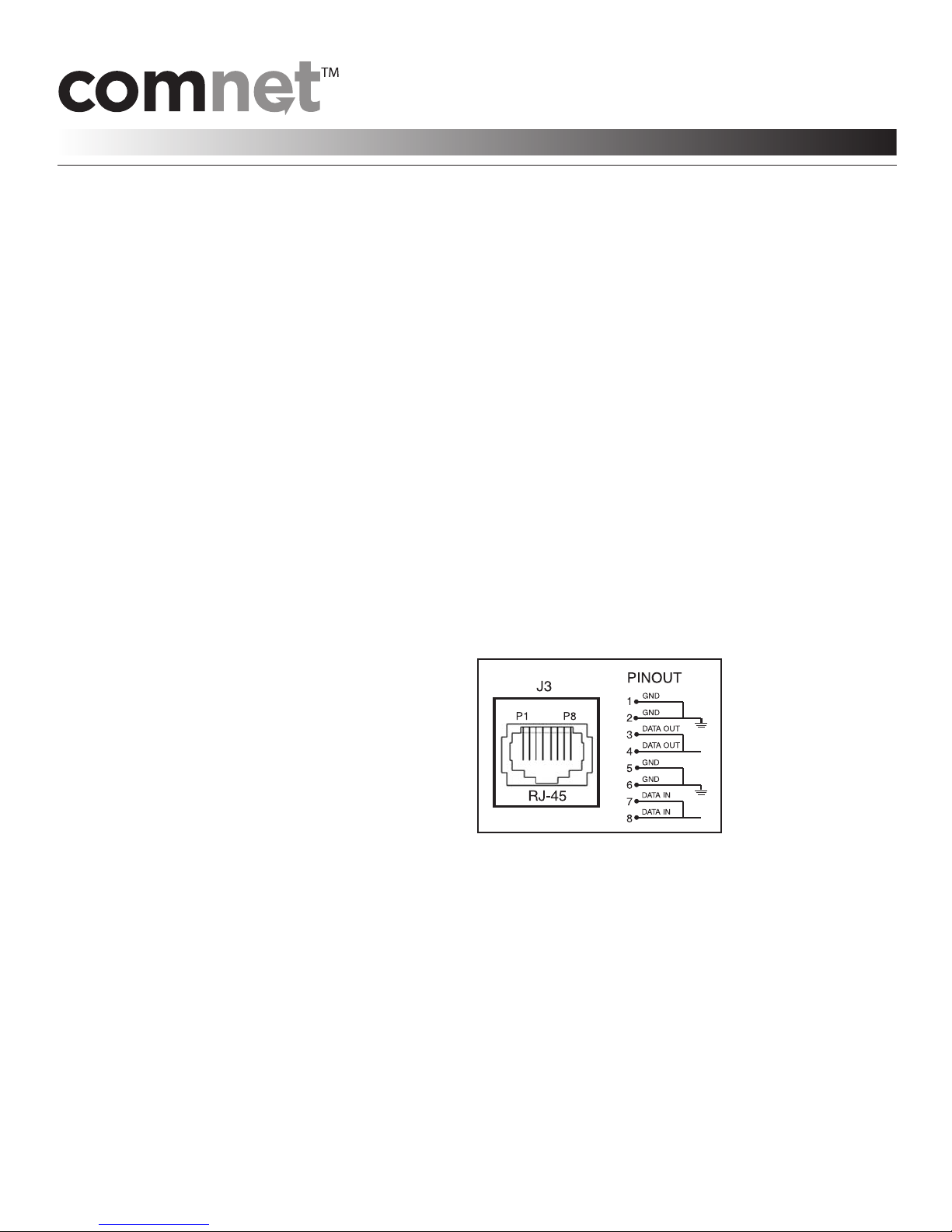
2) Linking port J3 originally used an RJ-45 receptacle.
This now has been changed to an
enhancements are summarized here. Please verify which version
“JABBER RESET” button. The silk screened printing was changed
“ANTI-STREAMING RESET” for this button.
RJ-11 receptacle.
3) The FDX55 was originally designed as a DCE device with a switch labeled “NA/DCE”
to allow for possible future use as a true “DCE/DTE” switch. The device has now changed to
allow for the selection of DCE or DTE via the front panel switch labeled DTE/DCE.
The setting of this switch is detailed later in this manual.
Page 2

FIG. 1
Installation and Operation Instructions
for the following ComNet
™
Model Numbers:
FDX55M1, FDX55M1AE,FDX55M1BE, FDX55M2, FDX55M2E,
FDX55S1, FDX55S1AE,FDX55S1BE, FDX55S2, FDX55S2E
RS-232/422 DROP AND REPEAT
FIG. 2
DATA TRANSCEIVER
FIG. 3
4-FIBER
LEDS: RED = “No Activity”
BLACK WITH WHITE STRIPE
GRN = “Activity”
NOTE: RED DOES NOT MEAN “Error”
DATA
CONNECTOR
LINKING
PORT
ANTI-STREAMING
SWITCH:
J1 CONNECTOR:
J3 CONNECTOR/
Anti-Streaming Timer (See Pg. 11, Fig.18)
Input/Output Connector (See Pg. 8, Fig. 10)
Connects two FDX55 t
ogether electrically.
A/B SWITCH: one must be set for “A” and one for “B”.
(See Pg. 8, Fig. 11)
DATA SWITCH:
Factory Default:“A”
Selects connections between optical and electrical ports.
(See Pg. 10, Fig. 16 and Fig. 17)
BLACK
FIG. 4
2-FIBER
X
X
NOTE: Remove Electrical
onnector for
C
Rack Mount Units
INS_FDX55_REVB
01/22/09
Page 1
Page 3

FDX55 SERIES
INSTALLATION INSTRUCTIONS
RS-232/422 DROP AND REPEAT
DATA TRANSCEIVER
1) ANTI-STREAMING SELECT SWITCH
The anti-streaming function is provided to protect the communications channel in the
event that a controller should go into a streaming or data-storming condition.
If the anti-streaming is to be used, it must be set to a setting that will exceed the longest
possible data transmission time that will exist on that channel.
most installations, the anti-streaming will not be utilized and the switch should be left in the
factory default “Off” position.
See Pg. 11, Fig.18.
2) DTE/DCE SELECT SWITCH
The purpose of this switch is to transpose the RS-232 data transmit and data receive signals.
Normally,this switch will be left in the factory default “DCE” position.
See Pg. 9, Fig.12 through Fig. 15.
3) LINKING PORT, J3
J3 is an RJ-11 connector utilized for electrically connecting two co-located FDX55 units.
For example,at some point on an east-to-west communications channel, it may be desired to
extend the channel in the north-to-south direction. A second FDX55 may be added in the same
cabinet as another existing FDX55, and the second unit would be utilized for extending the
channel in the north-to-south direction. A conventional straight-through interconnect cable
terminated at each end with RJ-11 connectors is required when connecting the two FDX55
units. It is desirable to keep the length of this cable as short as possible, so as to minimize
any possibility of stray electrical pick-up corrupting the quality of the data, which could
result in data errors.
See Pg. 8, Fig. 11 and Pg. 10, Fig. 17.
It should be noted that in
4) A/B SELECT SWITCH
The purpose of this switch is to transpose the data transmit and data receive signals when
connecting two co-located FDX55 units utilizing the J3 expansion port and a straight-through
data interconnect cable. One FDX55 will be set to “A” and the second FDX55 will be set to “B”.If a
cross over cable is used,then both FDX55s would be set to “A”. This interconnect cable should be
kept as short as possible to eliminate EMI/RFI noise injection. Refer to Figure 1 for
typical configuration. Factory default for this switch is “A”.
es -
c
our
er S
w
o
P
Use only a UL Class 2 indoor/dry or Class 3 outdoor/wet power supply.
ARNING:Unit is t
W
ARNING:This unit should b
W
of a lock and key or other means of security. Access should be limited to service personnel who
have been instructed about the reasons for the restrictions to the location. Any and all
precautions should be taken and controlled by the authority responsible for the location.
he pro
T
o b
t should only b
duc
e used with a Listed Class 2 or LPS power supply rated 9-12 VDC @ 1A.
e installed in a r
See Pg. 1, Fig.1.
ated from the recommended power source.
er
e op
icted access location; available through the use
estr
INS_FDX55_REVB
01/22/09
age 2
P
Page 4
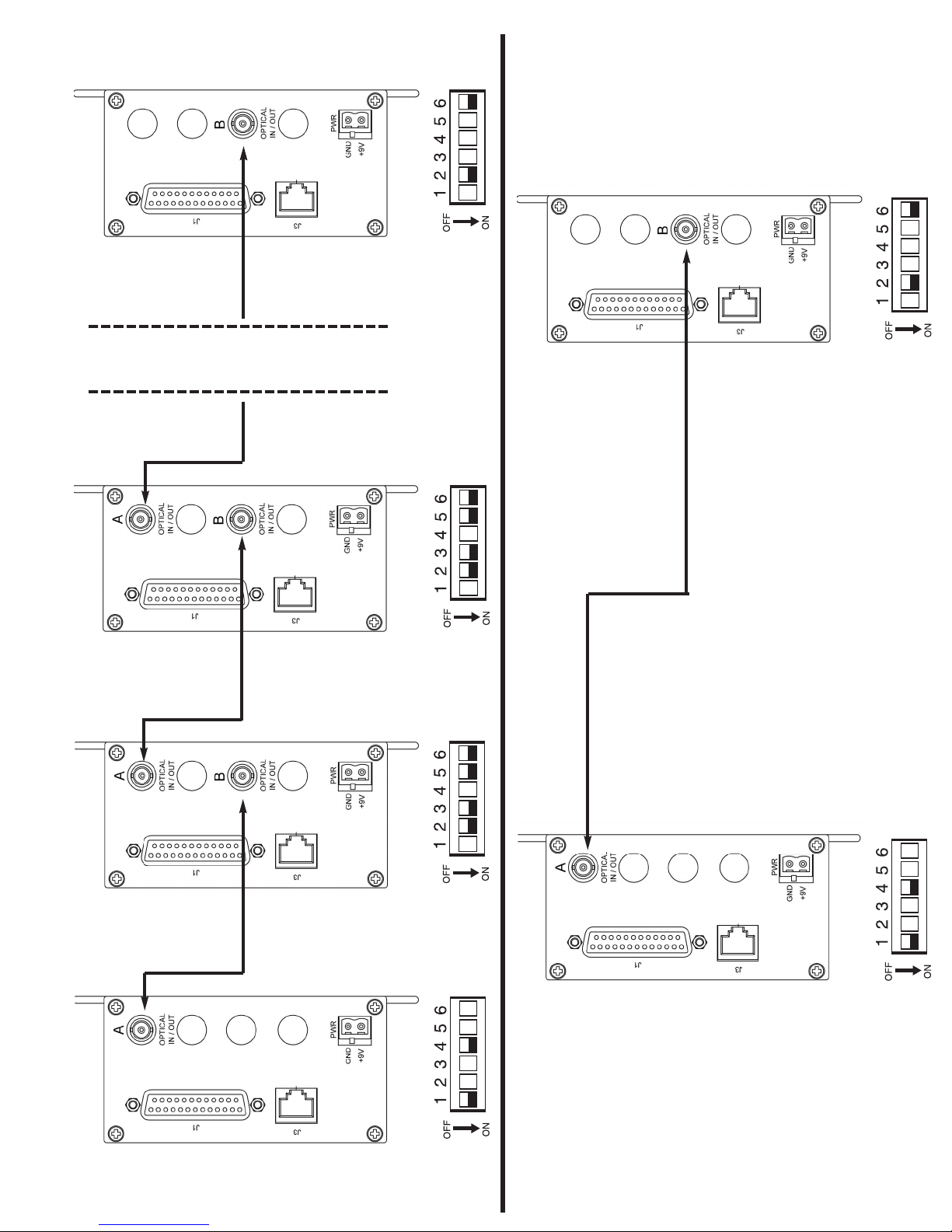
FIG. 5
FDX55M1BE
DATA
FDX55S1BE
DATADA
FDX55S1BE
FDX55M1BE
TYPICAL
Local Controller
FDX55 TYPICAL REPEATER CONFIGURATION
FDX55S1
FDX55M1
DATA
Local Controller Local Controller
CONFIGURATION
A
T
FDX55S1
FDX55M1
DA
Local Controller
FDX55 TYPICAL POINT-TO-POINT
A
T
FDX55S1AE
FDX55M1AE
Master Controller
FDX55S1AE
FDX55M1AE
DATA
Master Controller
INS_FDX55_REVB
01/22/09
Page 3
Page 5

FIG. 6
FDX55M1
DATA
FDX55S1
Local Controller
DATA
FDX55S1
FDX55M1
TYPICAL
Local Controller
FDX55 ALTERNATE DROP AND REPEAT CONFIGURATION
DATA
FDX55S1
FDX55M1
Local Controller
CONFIGURATION
DATA
FDX55S1
FDX55M1
Local Controller
FDX55 ALTERNATE POINT-TO-POINT
TA
DA
er Controller
ast
FDX55S1
FDX55M1
M
FDX55S1
FDX55M1
DATA
Master Controller
INS_FDX55_REVB
01/22/09
Page 4
Page 6

FDX55M2 TYPICAL DROP AND REPEAT CONFIGURAT ION
FDX55M2E
FDX55S2E
FDX55M2
FDX55S2
FDX55M2
FDX55S2
FDX55M2E
FDX55S2E
TYPICAL
DATA
DATA
DATA
DATA
FDX55M2E
FDX55S2E
FDX55M2E
FDX55S2E
FDX55M2 TYPICAL POINT-TO-POINT
CONFIGURATION
DATADATA
Master Controller
Local Controller
Master Controller
Local Controller
Local Controller Local Controller
FIG. 7
INS_FDX55_REVB
01/22/09
Page 5
Page 7

FDX55M2 ALTERNATE DROP AND REPEAT CONFIGURAT ION
FDX55M2
FDX55S2
FDX55M2
FDX55S2
FDX55M2
FDX55S2
FDX55M2
FDX55S2
TYPICAL
DATA
DATA
DATA
DATA
FDX55M2
FDX55S2
FDX55M2
FDX55S2
FDX55M2 ALTERNATE POINT-TO-POINT
CONFIGURATION
DATADATA
Master Controller
Local Controller
Master Controller
Local Controller
Local Controller Local Controller
FIG. 8
INS_FDX55_REVB
01/22/09
Page 6
Page 8

FIG. 9
DATA
FDX55S1BE
FDX55M1BE
TYPICAL
Local Controller
FDX55S1BE
FDX55M1BE
TYPICAL
DATA
FDX55S1
FDX55M1
ocal Controller
L
FDX55S1
FDX55M1
DATA
DATA
Local Controller Local Controller
FDX55S1
FDX55M1
FDX55 TYPICAL EXPANSION PORT J3 CONNECTION
A/B SWITCH = “A”
FDX55S1AE
FDX55M1AE
A
T
DA
Local Controller
AIGHT
RJ-11 STR
FDX55S1
FDX55M1
”
“B
CH =
THROUGH CABLE
A/B SWIT
DATA
Master Controller
FDX55S1AE
FDX55M1AE
A
T
DA
Local Controller
DATA
Master Controller
age 7
P
Page 9

FDX55 SERIES
INSTALLATION INSTRUCTIONS
FIG. 10
RS-232/422 DROP AND REPEAT
DATA TRANSCEIVER
FIG. 11
INS_FDX55_RE
01/22/09
Page 8
VB
Page 10

FDX55 SERIES
DCE
Device*
straight through
cable*
FDX55 Series
Device
DCE/DTE
set at “DTE”
DTE
Device*
straight through
cable*
FDX55 Series
Device
DCE/DTE
set at “DCE”
DCE
Device*
null modem or
crossover cable*
FDX55 Series
Device
DCE/DTE
set at “DCE”
DTE
Device*
null modem or
crossover cable*
*equipment supplied by others
FDX55 Series
Device
DCE/DTE
set at “DTE”
Data Input (RX)
Data Output (TX)
Data Input (RX)
Data Output (TX)
Data Output (TX)
Data Input (RX)
Data Output (TX)
Data Input (RX)
INSTALLATION INSTRUCTIONS
FIG. 12
FIG. 13
FIG. 14
RS-232/422 DROP AND REPEAT
DATA TRANSCEIVER
FIG. 15
INS_FDX55_RE
01/22/09
Page 9
VB
Page 11

FDX55 SERIES
INSTALLATION INSTRUCTIONS
FIG. 16
DATA SWITCH
SW
ON
IN
#1
A optical
#2
B optical
#3
B optical
#4
J1-DB25
#5
A optical
#6
J1-DB25
FIG. 17
A
RS-232/422 DROP AND REPEAT
DATA TRANSCEIVER
FUNCTION
OUT
J1-DB25
J1-DB25
A optical
A optical
B optical
B optical
B
OPTICAL
A
A
Communication Networks
te Drive • Danbury, CT 06810 • USA
a
or
p
or
3 C
Tel:203-796-5300 • Toll Free: 1-888-678-9427
www.comnet.net
B
OPTICAL
B
INS_FDX55_RE
01/22/09
Page 10
VB
Page 12

FDX55 SERIES
INSTALLATION INSTRUCTIONS
RS-232/422 DROP AND REPEAT
DATA TRANSCEIVER
FIG. 18
ANTI-STREAMING TIMER: Times RTS (Request to Send). If RTS is asserted for a time greater than
the Anti-Streaming settings, the electrical input is turned OFF permanently.
To RESET: Press the RESET button on the front panel.
TS/CTS INDICATORS
R
RTS: RED RTS is OFF
GRN RTS is ON
CTS: RED CTS is OFF
GRN CTS is ON
Note: If the RTS signal is turned ON for a time greater than the Anti-Streaming Time Setting, then the RTS
will be ON, but the CTS will be RED (Off) and the FAIL LIGHT will be GRN (Failure Asserted).
When the RESET button is pressed, the FAIL LIGHT switches to RED and the RTS/CTS works again.
OFF
(Factory Default)
4 SECONDS
8 SECONDS
Communication Networks
3 C
orporate Drive • Danbury,CT 06810 • USA
Tel:203-796-5300 • Toll Free: 1-888-678-9427
omnet.net
.c
www
ANTI-STREAMING
ANTI-STREAMING
TIMER
16 SECONDS
32 SECONDS
64 SECONDS
INS_FDX55_RE
VB
01/22/09
age 11
P
 Loading...