

Page 1

INSTALLATION AND OPERATION MANUAL
FDX50M2, FDX51M2
RS232/422 POINT-TO-POINT DATA TRANSCEIVER
The ComNet™ FDX50M2 and FDX51M2 data transceivers are interchangeable
by application and provide point-to-point transmission of simplex or duplex EIA
RS232/RS422 data signals over two multimode optical fibers. The transceivers are
transparent to data encoding allowing for broad-range compatibility.
Each transceiver incorporates a bi-color (Red/Green) indicating LED for monitoring
proper system operation. See Figure 6 on Page 4 for LED Indicator explanations.
The FDX50M2 has a small footprint and is designed for surface mounting. The
FDX51M2 may be directly plugged into the ComNet Rack (Part C1) or can operate as
a standalone module, or may be DIN-rail mounted by the addition of ComNet model
DINBKT1 adaptor plate. See Figure A on Page 5 for mounting instructions.
See Figures 1 – 6 for complete installation details.
INS_FDX50M2_FDX51M2_REV–
04/27/12
PAGE 1
Rev. 9.19.12
Page 2
GND
+Vin
232
422
GND
+OUT
-OUT
- IN
+IN
OUT
IN
PWR
DATA
OPTICALOUT
OPTICALIN
GND
+Vin
232
422
GND
+OUT
-OUT
- IN
+IN
OUT
IN
PWR
DATA
OPTICALOUT
OPTICALIN
INSTALLATION AND OPERATION MANUAL FDX50M2, FDX51M2
FIGURE 1 – FDX51M2 COMFIT TRANSCEIVER
MULTIMODE
OPTICAL FIBER
BLACK
BLACK WITH WHITE STRIPE/RED
Power Supply:
Surface Mount: 8–15 VDC @ 70mA
Rack Mount: From Rack
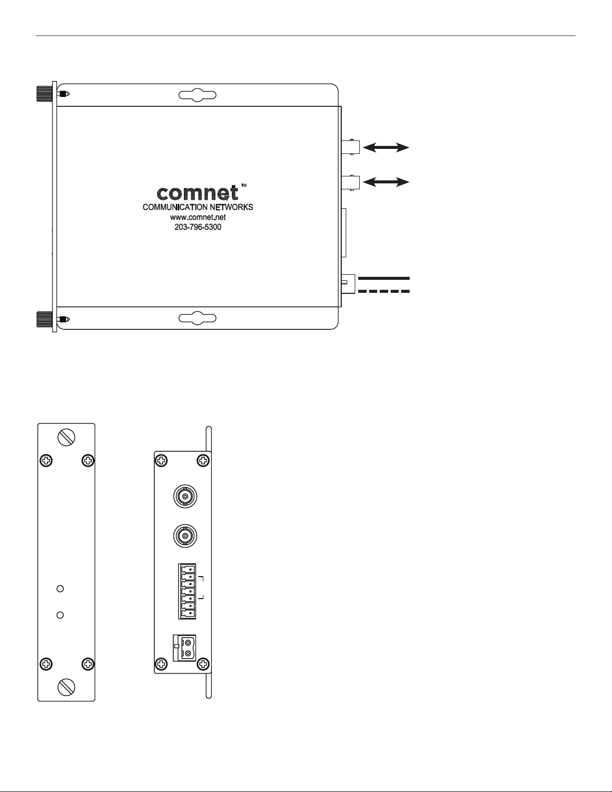
FIGURE 2 – FDX51M2 TRANSCEIVER
REAR PANELFRONT PANEL
FDX51M2
2FIBER
RS232/422
DATA LINK
RECEIVE
DATA
TRANSMIT
DATA
TECH SUPPORT: 1.888.678.9427
OPTICALOUT
OPTICALIN
DATA
GND
+OUT
-OUT
- IN
+IN
OUT
IN
PWR
GND
+Vin
422
232
NOTE: Remove Electrical
Connector for Rack Mount Units
INS_FDX50M2_FDX51M2_REV–
04/27/12
PAGE 2
Page 3

GND
+9V
OPTICAL
OUT
6
5
4
3
2
1
-RS422 OUT
+RS422 IN
RS232IN
2
1
RECEIVE
DATA
TRANSMIT
DATA
7
+RS422 OUT
-RS422 IN
RS232OUT
GND
OPTICAL
IN
FDX50M2
2FIBER
RS232/422
DATA LINK
TM
GND
+9V
OPTICAL
OUT
6
5
4
3
2
1
-RS422 OUT
+RS422 IN
RS232IN
2
1
RECEIVE
DATA
TRANSMIT
DATA
7
+RS422 OUT
-RS422 IN
RS232OUT
GND
OPTICAL
IN
FDX50M2
2FIBER
RS232/422
DATA LINK
TM
INSTALLATION AND OPERATION MANUAL FDX50M2, FDX51M2
FIGURE 3 – FDX50M2 SURFACE MOUNT TRANSCEIVER
MULTIMODE
OPTICAL FIBER
BLACK
BLACK WITH WHITE STRIPE/RED
Power Supply:
Surface Mount: 8–15 VDC @ 70mA
FIGURE 4 – FDX50M2 TRANSCEIVER
REAR PANELFRONT PANEL
TECH SUPPORT: 1.888.678.9427
INS_FDX50M2_FDX51M2_REV–
04/27/12
PAGE 3
Page 4

INSTALLATION AND OPERATION MANUAL FDX50M2, FDX51M2
OPTICALOUT
OPTICALIN
FIGURE 5 – DATA SETTINGS
FDX51M2 COMFIT TRANSCEIVER
DATA
GND
+OUT
-OUT
- IN
+IN
OUT
IN
FDX50M2 SURFACE MOUNT TRANSCEIVER
Connection Labels on Cover
7
6
5
4
3
2
1
+RS422 OUT
-RS422 OUT
-RS422 IN
+RS422 IN
RS232OUT
RS232IN
GND
422
232
}
}
RS422 OUT
}
RS422 IN
}
RS422 OUT
RS422 IN
GND
OUT
IN
GND
OUT
IN
}
RS232
}
RS232
FIGURE 6 – LED INDICATORS
RECEIVE DATA TRANSMIT DATA
GREEN Activity Activity
RED No Activity No Activity
OFF Unit Not Powered Up Unit Not Powered Up
TECH SUPPORT: 1.888.678.9427
INS_FDX50M2_FDX51M2_REV–
04/27/12
PAGE 4
Page 5

MECHANICAL INSTALLATION INSTRUCTIONS
INSTALLATION CONSIDERATIONS
The FDX51M2 fiber-optic link is supplied as a Standalone/Rack module.
The FDX50M2 fiber-optic link is supplied as a Standalone module.
Units should be installed in dry locations protected from extremes of
temperature and humidity.
C1-US, C1-EU, C1-AU OR C1-CH CARD CAGE RACKS
CAUTION: Although the units are hot-swappable and may be installed
without turning power off to the rack, ComNet recommends that the
power supply be turned off and that the rack power supply is disconnected
from any power source. Note: Remove electrical connector before
installing in card cage rack.
1. Make sure that the card is oriented right side up, and slide it into the
card guides in the rack until the edge connector at the back of the card
seats in the corresponding slot in the rack’s connector panel. Seating
may require thumb pressure on the top and bottom of the card’s front
panel.
CAUTION: Take care not to press on any of the LEDs.
2. Tighten the two thumb screws on the card until the front panel of the
card is seated against the front of the rack.
FIGURE A
Dimensions are for a standard ComNet one slot module
.156 [3.96 mm]
.313 [7.95 mm]
WARNING: Unit is to be used with a Listed Class 2 or LPS power supply.
IMPORTANT SAFEGUARDS:
A) Elevated Operating Ambient - If installed in a closed or multi-unit rack
assembly, the operating ambient temperature of the rack environment may
be greater than room ambient. Therefore, consideration should be given to
installing the equipment in an environment compatible with the maximum
ambient temperature (Tma) specified by the manufacturer.
B) Reduced Air Flow - Installation of the equipment in a rack should be such
that the amount of air flow required for safe operation of the equipment is not
compromised.
FIGURE B
Dimensions are for a standard ComNet small size module
3 CORPORATE DRIVE | DANBURY, CT 06810 | USA
T: 203.796.5300 | F: 203.796.5303 | TECH SUPPORT: 1.888.678.9427 | INFO@COMNET.NET
8 TURNBERRY PARK ROAD | GILDERSOME | MORLEY | LEEDS, UK LS27 7LE
T: +44 (0)113 307 6400 | F: +44 (0)113 253 7462 | INFO-EUROPE@COMNET.NET
© 2012 Communications Ne tworks Cor poration. All Rights Reser ved. “ComNet ” and the “ComNet L ogo” are registered trademarks of C ommunication Networ ks, LLC.
INS_FDX50M2_FDX51M2_REV–
04/27/12
PAGE 5
 Loading...