

Page 1
INSTALLATION AND OPERATION MANUAL
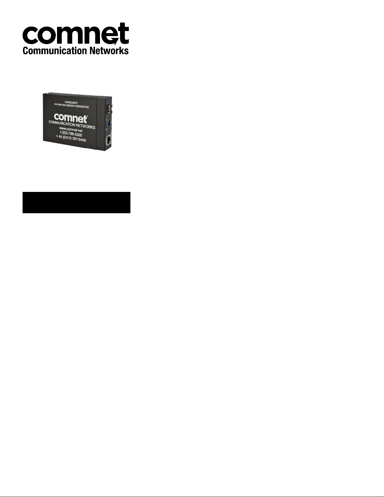
CWGE2SFP
Commercial Grade 10/100/1000BASE-T(X) to
1000BASE-FX Gigabit Ethernet Media Converter
This manual serves the following
ComNet Model Numbers:
CWGE2SFPM2
CWGE2SFPS2
CWGE2SFP
The ComNet CWGE2SFP Ethernet media converter series are one-channel Ethernet
electrical to optical media converters. These auto-negotiating devices accept a
10/100/1000 Mbps electrical input and convert this to a 1000 Mbps optical output.
These devices use either one or two optical fibers, depending upon the selection of
either included or sold-separately SFP optical module. These devices can be used in
stand-alone mode or can be installed within the ComNet CWCHASSIS 19 inch rack.
Rev. 12.5.17
Page 2

INSTRUCTION MANUAL CWGE2SFP
Contents
Introduction 3
Features 3
Hardware Description 4
Front Panel 5
Rear Panel 5
Por t s 5
DIP-switch 7
TECH SUPPORT: 1.888.678.9427
INS_CWGE2SFP Rev. 12.5.17 PAGE 2
Page 3

INSTRUCTION MANUAL CWGE2SFP
Introduction
The ComNet CWGE2SFP series is a cost-effective solution for converting 10/100/1000Base-TX
electrical to 1000Base-FX fiber optic cable, It allows you to extend the distance of your 1000BaseFX network up to 550 meters for multi-mode fiber or up to 15 kilometers for single-mode fiber.
The CWGE2SFP series gives you maximum flexibility with its empty SFP slot supporting any of the
ComNet 1 Gbps SFP modules offering options for different connector types and distances up to 120
kilometers. The CWGE2SFP module provides you with one SFP fiber port for your fiber optic cable
and one Ethernet RJ45 port (Auto MDI/MDIX) for your 10/100/1000Base-TX copper cable connection.
There are three DIP switches to set the operation mode and link loss forwarding function.
Features
ComNet CWGE2SFP Series
» Complies with IEEE 802.3, 802.3u, and 802.3x standards.
» Converts between UTP cabling and fiber-optic cable.
» One RJ-45 connector, Auto-MDI/MDIX for UTP port.
» Supports 10/100/1000 Mbps Auto-negotiation for UTP port.
» Fiber optic cabling connectivity up to 15 km.
» Store-and-forward switching architecture.
» 3 DIP-switches to set the operation mode and Link- Lost-Forwarding function.
» 6 LEDs for: Speed, Link, Activity, Full, Collision, and per unit Power.
» External DC power adapter 5-12 VDC.
» FCC Class A, CE Mark certification
Package Contents
Stand-alone converter module package contains following items:
» Media Converter
» AC-DC Power Adapter
» User Guide
Compare the contents of your converter module with the checklist above. If any item is damaged
or missing, please contact your local dealer for service.
TECH SUPPORT: 1.888.678.9427
INS_CWGE2SFP Rev. 12.5.17 PAGE 3
Page 4

INSTRUCTION MANUAL CWGE2SFP
Hardware Description
The CWGE2SFP Series Media Converter dimensions (L × W × H): 120 × 85 × 26 mm
TECH SUPPORT: 1.888.678.9427
INS_CWGE2SFP Rev. 12.5.17 PAGE 4
Page 5

INSTRUCTION MANUAL CWGE2SFP
Front Panel
The Front Panel of the CWGE2SFP series media converter module consists of one Gigabit SFP
port (supplied either empty or with an included SFP module, depending on model ordered), one
Gigabit RJ45 copper Port (Auto MDI/MDIX), and 6 LED Indicators (SPD, LK/ACT, FDX, Fiber LK/
ACT, FDX/COL, and PWR).
Fast Fiber Conver ter Module - SC Model
Rear Panel
The rear panel contains a 2.1mm power socket. This power socket accepts 5-12 VDC @ 2.7 W.
Fast Fiber Conver ter Module - SC Model
Ports
Copper Port (Auto MDI/MDIX): The Ethernet RJ45 port will auto-sense for 10Base-T, 100Base-TX,
or 1000Base-T connections. Auto MDI/MDIX means that you can connect to another Switch or
workstation without changing non-crossover or crossover cabling.
SFP Port: This port is for 1000Base-FX connections with SFP modules.
TECH SUPPORT: 1.888.678.9427
INS_CWGE2SFP Rev. 12.5.17 PAGE 5
Page 6

INSTRUCTION MANUAL CWGE2SFP
LED Indicators
There are 6 diagnostic LEDs located on the Front panel of the media converter. They provide realtime information of system and operational status. The following table provides descriptions of the
LED status and their meanings.
LED Color Status Description
PWR Green On Power On
SPD Green On 1000 Mbps UTP Speed
Amber On 100 Mbps UTP Speed
Off 10 Mbps UTP Speed
LNK /ACT (UTP) Green On The unit is linking with its link partner.
Green Blinking The unit is transmitting or receiving packets from UTP devices.
Off No device attached
FDX (UTP) Amber On The UTP port is operating in full-duplex mode.
Off Half-duplex mode or no device attached.
LNK/ACT (Fiber) Green On The unit is linking with its link partner.
Green Blinking The unit is transmitting or receiving packets from UTP devices.
Off No device attached
FDX/COL (Fiber) Amber On The fiber port is operating in full-duplex mode.
Off No device attached.
TECH SUPPORT: 1.888.678.9427
INS_CWGE2SFP Rev. 12.5.17 PAGE 6
Page 7

INSTRUCTION MANUAL CWGE2SFP
DIP-switch
The DIP-switch is used to configure the operation mode for LLF (Link Lost Forwarding) and
operation mode for the device traffic. The default value of each Dipswitch is OFF.
SW No Status Description
1 ON LLF Enable
OFF LLF Disable
2 ON Pure Converter mode
OFF Switch Converter mode
3 ON Reserved
OFF Reserved
Link Lost Forwarding (DIP-Switch 1): When LLF is enabled, it will allow a copper port link failure to
be reported to the SFP side and also allow an SFP link failure to be reported to the copper side.
Therefore, a link loss forward feature is provided in both copper and SFP ports.
Pure Converter mode (DIP-Switch 2): When pure converter mode is enabled (on), the media
converter operates with the minimum latency. The transmission flow does not wait until the entire
frame is ready, but instead it forwards the received data immediately after the data has been
received. (The RJ45 port should be forced at 1000M in this application). When DIP-Switch is in
Switch Converter mode (off), the media converter will function the same as a Switch in store-andforward mode.
Note: a) Please don’t change the DIP-switch settings when the copper or SFP port is transmitting
or receiving data. It may cause some data error.
b) Please power off then power on when you change the DIP-switch settings.
TECH SUPPORT: 1.888.678.9427
INS_CWGE2SFP Rev. 12.5.17 PAGE 7
Page 8

INSTRUCTION MANUAL
ComNet Customer Service
Customer Care is ComNet Technology’s global service center, where our professional staff is
ready to answer your questions at any time.
Email ComNet Global Service Center: customercare@comnet.net
3 CORPORATE DRIVE | DANBURY, CT 06810 | USA
T: 203.796.5300 | F: 203.796.5303 | TECH SUPPORT: 1.888.678.9427 | INFO@COMNET.NET
8 TURNBERRY PARK ROAD | GILDERSOME | MORLEY | LEEDS, UK LS27 7LE
T: +44 (0)113 307 6400 | F: +44 (0)113 253 7462 | INFO-EUROPE@COMNET.NET
© 2017 Communications Ne tworks Cor poration. All Rights Reserved. “ComNet” and the “ComNet Logo” are registered tr ademarks of Communication Net works, LLC .
 Loading...