

Page 1
INSTALLATION AND OPERATION MANUAL
CWGE2SC(M,S)2
COMMERCIAL GRADE 10/100/1000BASE-T(X) TO
1000BASE-SX/LX GIGABIT ETHERNET MEDIA CONVERTER
The ComNet™ CWGE2SC(M,S)2 Ethernet media converters are designed to transmit
and receive 10/100/1000 Mbps data over multimode or single mode optical fiber.
The electrical interface will Auto-Negotiate to a 10, 100, or 1000 Mbps Ethernet rate
without any adjustments. The optical interface operates at a 1000 Mbps Ethernet
rate. These media converters are commercial grade for light industrial use.
Indicating LEDs are provided for confirming operating status. See Figure 4 on
Page 3 for LED explanations.
See Figures 1 – 5 for complete operation instructions.
INS_CWGE2SC(M,S)2_REV- 06/22/12 PAGE 1
Page 2
INSTALLATION AND OPERATION MANUAL CWGE2SC(M,S)2
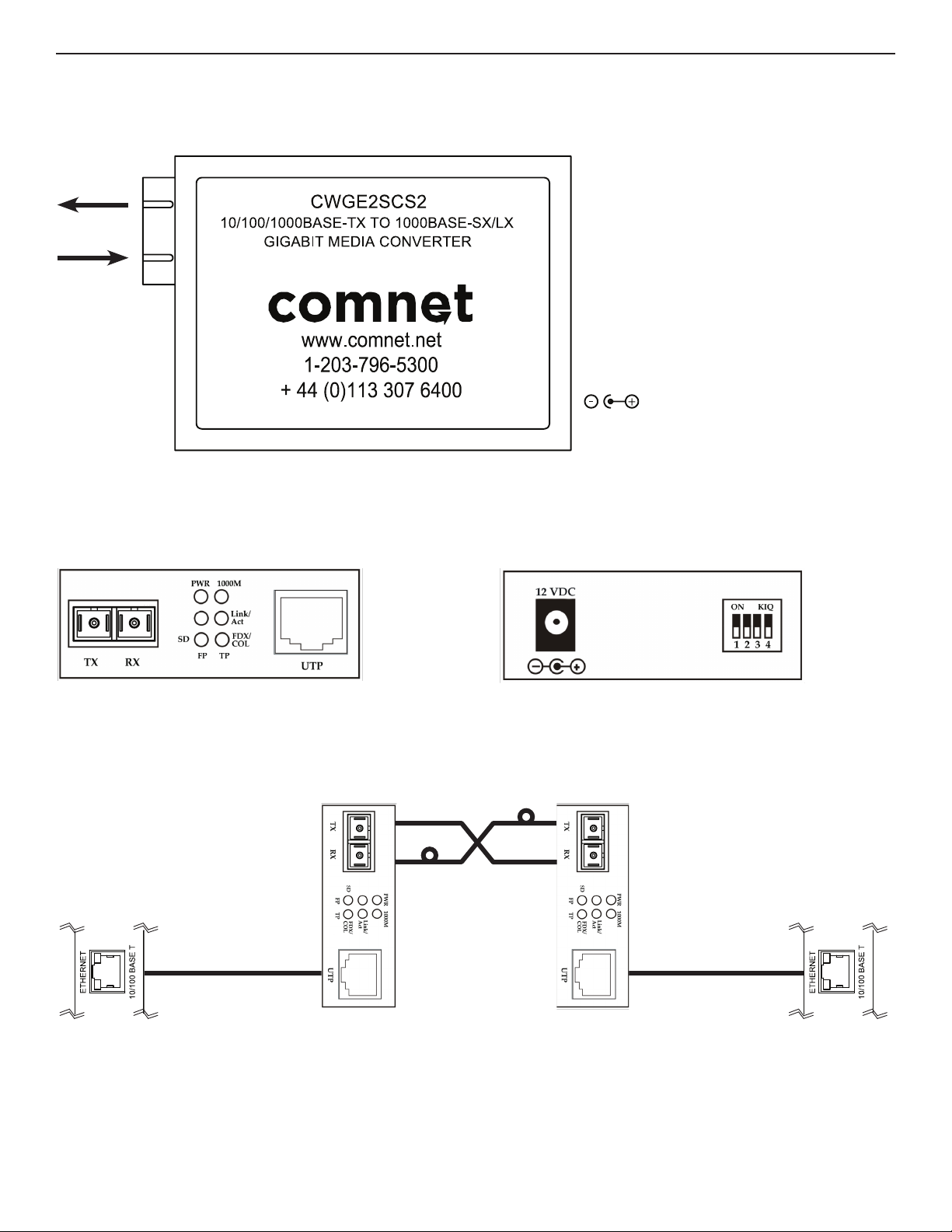
FIGURE 1 – CWGE2SC(M,S)2 TRANSCEIVER
TX
RX
2.5mm Center Positive Plug
Operating Voltage: 9 to 12 VDC
Power Consumption: 2W
FIGURE 2 – CWGE2SC(M,S)2 TRANSCEIVER
FIGURE 3 – POSSIBLE ETHERNET CONFIGURATION
Ethernet IEEE 802.3 Network Element determined by user.
2 OPTICAL FIBERS
SC CONNECTORS
MULTIMODE
REAR PANELFRONT PANEL
CAT5e/6 with
RJ45 Connections
Ethernet IEEE 802.3
Network Element
TECH SUPPORT: 1.888.678.9427
CWGE2SCM2 CWGE2SCM2
CAT5e/6 with
RJ45 Connections
Ethernet IEEE 802.3
Network Element
INS_CWGE2SC(M,S)2_REV- 06/22/12 PAGE 2
Page 3

INSTALLATION AND OPERATION MANUAL CWGE2SC(M,S)2
FIGURE 4 – INDICATING LEDS
LED Status Meaning
Power On Power is on
Link/ACT (FP)
Link/ACT (TP)
FDX/COL
FX or SD On Fiber signal is detected
1000M
On Fiber link port is connceted
Flashing Packets sending/receiving
On TX port is connected
Flashing Packets sending/receiving on TX port
On TX port full duplex mode active
Off TX port half duplex mode active
On TX in 1000 Mbps speed
Off TX in 100 Mbps speed
FIGURE 5 – DIP SWITCH POSITIONS
DIP Switch Position
Function
Link Fault Pass-through function. DIP Switches 1 and 4 must be set
to opposite positions (default is 1 ON/4 OFF)
Pass-through Mode / Enable Jumbo Frame ON ON
Enable Store and Forward Mode (default) OFF OFF
Modified Cut-through mode ON OFF
1 2 3 4
OFF/
ON
ON/
OFF
TECH SUPPORT: 1.888.678.9427
INS_CWGE2SC(M,S)2_REV- 06/22/12 PAGE 3
Page 4

MECHANICAL INSTALLATION INSTRUCTIONS
INSTALLATION CONSIDERATIONS
This fiber-optic link is supplied as a Standalone module. Units should be installed in dry locations protected from extremes of temperature and humidity.
CAUTION: Take care not to press on any of the LEDs.
WARNING: Unit is to be used with a Listed Class 2 power supply.
IMPORTANT SAFEGUARDS:
A) Elevated Operating Ambient - If installed in a closed or multi-unit rack assembly, the operating ambient temperature of the rack environment may be greater than
room ambient. Therefore, consideration should be given to installing the equipment in an environment compatible with the maximum ambient temperature (Tma)
specified by the manufacturer.
B) Reduced Air Flow - Installation of the equipment in a rack should be such that the amount of air flow required for safe operation of the equipment is not compromised.
3 CORPORATE DRIVE | DANBURY, CT 06810 | USA
T: 203.796.5300 | F: 203.796.5303 | TECH SUPPORT: 1.888.678.9427 | INFO@COMNET.NET
8 TURNBERRY PARK ROAD | GILDERSOME | MORLEY | LEEDS, UK LS27 7LE
T: +44 (0)113 307 6400 | F: +44 (0)113 253 7462 | INFO-EUROPE@COMNET.NET
© 2014 Communica tions Networ ks Corporation. All Rights Reser ved. “ComNet ” and the “ComNet Logo” are regis tered trademarks of Communic ation Networks, L LC.
INS_CWGE2SC(M,S)2_REV- 06/22/12 PAGE 4
 Loading...