

Page 1
INSTALLATION AND OPERATION MANUAL
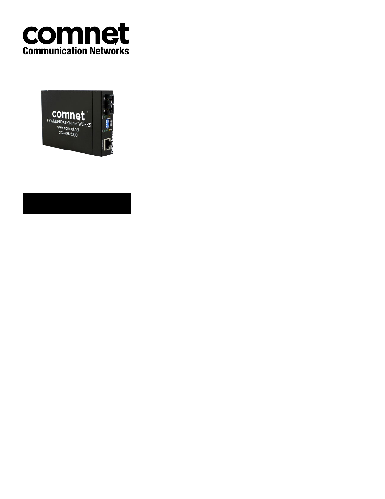
CWFE2SC(M,S)2
Commercial Grade 10/100 Mbps Ethernet
2 Port Electrical-to-Optical Media Converter
The ComNet ValueLine CWFE2SC(M,S)2 Ethernet 2-port media converters are designed
to transmit and receive a single channel of 10/100 Mbps data over multimode or single
mode optical fiber. The electrical interface will Auto-Negotiate to a 10 Mbps, or 100 Mbps
Ethernet rate without any adjustments. The optical interface operates at a 100 Mbps
Ethernet rate. These media converters are commercial grade for light industrial use.
Rev. 11.17.17
Page 2

INSTRUCTION MANUAL CWFE2SC(M,S)2
Contents
Introduction 3
Features 3
Hardware Description 4
Front Panel 4
Ports 4
LED Indicators 5
DIP-switch 6
Rear Panel 7
Cabling 7
Connections 7
Problem Solving 8
Optical Fiber Specifications 8
Optical Specifications of Transceivers 8
Technical Specifications 9
TECH SUPPORT: 1.888.678.9427
QSG_CWFE2SC(M,S)2 Rev. 11.17.17 PAGE 2
Page 3

INSTRUCTION MANUAL CWFE2SC(M,S)2
Introduction
The ComNet CWFE2SC(M,S)2 is a cost-effective solution for converting 10/100Base-TX electrical
to and 100Base-FX fiber optic cable, It allows you to extend the distance of your 100Base-FX
network up to 3 kilometers for multi-mode fiber or up to 30 kilometers for single-mode fiber.
The ComNet CWFE2SC(M,S)2 gives you the option of choosing between the most popular fiber
cabling connectors: SC/multi-mode fiber connector and SC single-mode fiber connectors. The
CWFE2SC(M,S)2 module provides you with one fiber port for your fiber optic cable and one
Ethernet RJ45 port (Auto MDI/MDIX) for your 100Base-TX copper cable connection. There are 4
DIP- switches to set the operation mode for UTP, Fiber ports and link loss forwarding function.
Features
ComNet CWFE2SC(M)(S)2
» Complies with IEEE 802.3, 802.3u, and 802.3x standards.
» Converts between UTP cabling and fiber-optic cable.
» One RJ-45 connector, Auto-MDI/MDIX for UTP port.
» Supports 10/100 Mbps Auto-negotiation for UTP port.
» Fiber optic cabling connectivity up to 30Km.
» Store-and-forward switching architecture.
» Two SC fiber connectors for 100Base-FX optical transmission.
» 4 DIP-switches to set the operation mode and Link- Lost-Forwarding function.
» 6 LEDs for per port: 100, Link, Activity, Full, Collision, and per unit Power.
» External DC power adapter 5-12 VDC.
» FCC Class A, CE Mark certification
Package Contents
» Stand-alone converter module package contains following items.
» Media Converter
» AC-DC Power Adapter
» User Guide
Compare the contents of your converter module with the checklist above. If any item is damaged
or missing, please contact your local dealer for service.
TECH SUPPORT: 1.888.678.9427
QSG_CWFE2SC(M,S)2 Rev. 11.17.17 PAGE 3
Page 4
INSTRUCTION MANUAL CWFE2SC(M,S)2
Hardware Description
Unit dimension (L × W × H) is: 119 × 85 × 26 mm
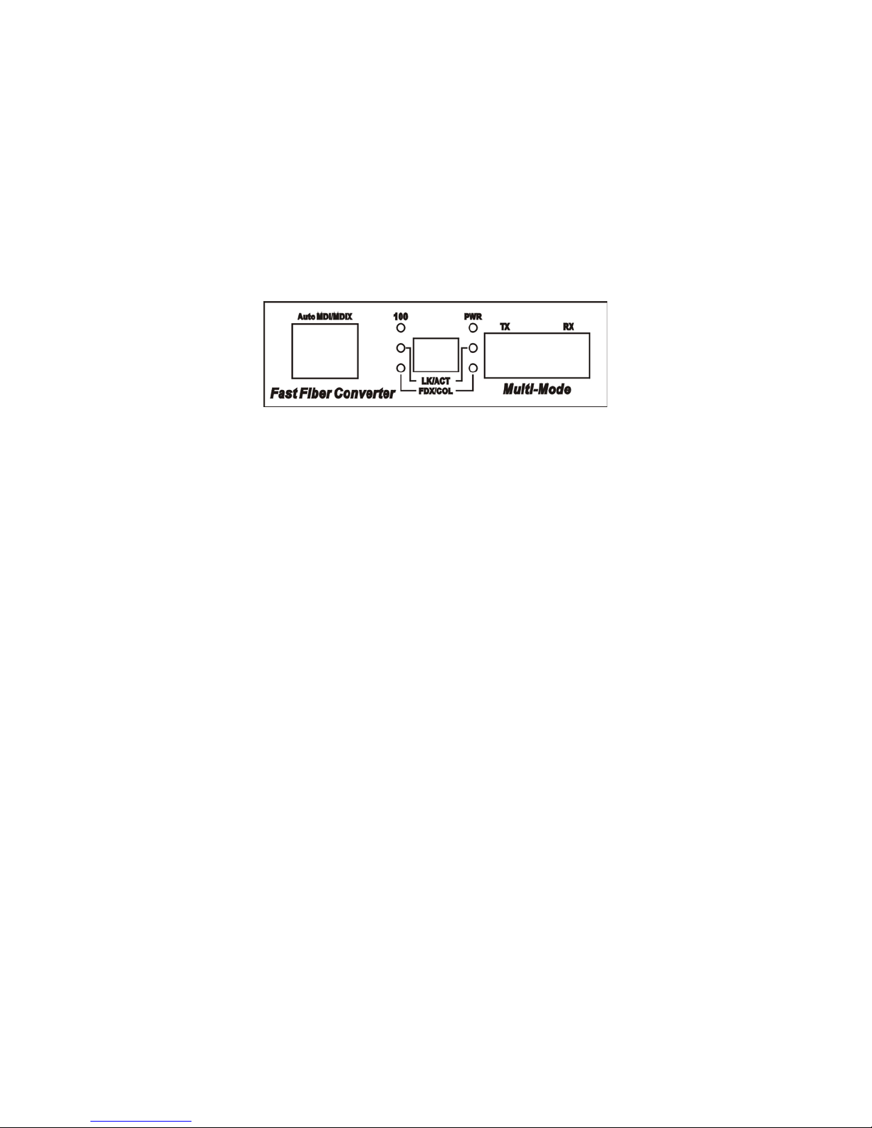
Front Panel
The Front Panel of the ComNet CWFE2SC(M,S)2 consists of one RJ-45 Port (Auto MDI/MDIX),
6 LED Indicators (UTP 100, LK/ACT, FDX/COL, Fiber LK/ACT, FDX/COL and PWR) and one fiber
100Base-FX Port.
Fast Fiber Conver ter Module - SC Model
Ports
RJ-45 Port (Auto MDI/MDIX): the Ethernet RJ-45 will auto-sense for 10Base-T or 100Base-TX
connections. Auto MDI/MDIX means that you can connect to another switch or workstation
without changing non-crossover or crossover cabling.
Fiber Port: This port is for 100 Base-FX connections.
TECH SUPPORT: 1.888.678.9427
QSG_CWFE2SC(M,S)2 Rev. 11.17.17 PAGE 4
Page 5

INSTRUCTION MANUAL CWFE2SC(M,S)2
LED Indicators
There are 6 diagnostic LEDs located on the Front panel of the media converter. They provide realtime information of system and optional status. The indicator includes Power, UTP 100, LK/ACT,
FDX/COL, Fiber LK/ACT, FDX/COL. The following table provides description of the LED status and
their meanings.
LED Color Status Description
PWR Green On Power On
100 Green On 100 Mbps UTP Speed
Off 10 Mbps UTP Speed
LK /ACT (UTP) Green On The unit is linking with its link partner.
Green Blinking The unit is transmitting or receiving packets from UTP devices.
Off No device attached
LK/ACT (Fiber) Green On The unit is linking with its link partner.
Green Blinking The unit is transmitting or receiving packets from FX devices.
Off No device attached
FDX/COL (UTP) Orange On The UTP port is operating in full-duplex mode.
Orange Blinking Collision of packets is occurring in the port.
Off Half-duplex mode or no device attached.
FDX/COL (Fiber) Orange On The fiber port is operating in full-duplex mode.
Orange Blinking Collision of packets is occurring in the port.
Off Half-duplex mode or no device attached.
TECH SUPPORT: 1.888.678.9427
QSG_CWFE2SC(M,S)2 Rev. 11.17.17 PAGE 5
Page 6

INSTRUCTION MANUAL CWFE2SC(M,S)2
DIP-switch
The DIP-switch is used to configure operation mode for LLF (Link Lost Forwarding) and operation
mode for UTP/Fiber port. The default value of DIP switch is OFF.
SW No Status Description
1 ON UTP 100 Mbps Full Duplex Mode
OFF UTP Auto-Negotiate
2 ON Fiber in Half Duplex
OFF Fiber in Full Duplex
3 ON LLF Enable
OFF LLF Disable
4 ON Pure Converter mode
OFF Switch Converter mode
Link Lost Forwarding (DIP-Switch 3): When LLF is enabled, it allows UTP link failures to be reported
to the fiber side and also allows a fiber link failure to be reported to the UTP side. Therefore, a link
loss forward feature is provided in both UTP and fiber side.
Pure Converter mode (DIP-Switch 4): When the pure converter mode is enabled (on), it operates
with minimal latency. The transmission flow does not wait until the entire frame is ready, but
instead it forwards the received data immediately after the data has been received. The UTP port
should be forced at 100M in this application. When DIP-Switch is in Switch Converter mode (off),
the converter function is same as Switch Hub.
Note: Do not change the DIP-switch setting when UTP or fiber port is transmitting or receiving
data. It may cause some data errors. If you change the DIP-switch setting, please power off
the converter and power it on again to make the setting effective.
TECH SUPPORT: 1.888.678.9427
QSG_CWFE2SC(M,S)2 Rev. 11.17.17 PAGE 6
Page 7

INSTRUCTION MANUAL CWFE2SC(M,S)2
Rear Panel
The rear panel contains a power socket, which accepts 5-12 VDC @ 2.7 W.
Connect the included Power Supply to the rear panel DC IN jack.
Plug the AC input of the Power Supply to a commercial power source.
DC IN
Fast Fiber Conver ter Module - Rear Panel
Cabling
» For the Twisted-pair segment unshielded twisted pair (UTP) or shielded twisted pair (STP)
cabling can be used. The cable must comply with the IEEE 802.3u 100Base TX standard for
Category 5. The cable between the converter and the link partner (switch, hub, workstation,
etc.) must be less than 100 meters (328 feet) long.
» For the single mode fiber optic segment, use 9/125 μm single mode fiber cable. You can
connect two devices over a distance of 30 kilometers.
» For the multimode fiber optic segment use 50 or 62.5/125 µm multimode fiber cable. You can
connect two devices up to a 3 kilometer (2 mile) distance.
Connections
Ethernet
Device
POWER
SUPPLY
CAT5e CAT5e
CWFE2SC
2 Multimode
or Single Mode
Optical Fibers
CWFE2SC
Ethernet
Device
POWER
SUPPLY
TECH SUPPORT: 1.888.678.9427
QSG_CWFE2SC(M,S)2 Rev. 11.17.17 PAGE 7
Page 8

INSTRUCTION MANUAL CWFE2SC(M,S)2
Problem Solving
» Check the DIP-switch configuration. It must be set in the same operational mode as the
corresponding link.
» Select the proper UTP/fiber optic cable to construct your network. The single-mode media
converter must use single-mode fiber optic cable. Please check that you are using the right
cable.
Optical Fiber Specifications
The following table shows the optical Fiber Specification
Module Name Wavelength (nm) Avg. Launch Power (dB) Avg. Sensitivity (dB)
CWFE2SCM2 1310 nm -20 dB -30 dB
CWFE2SCS2 1310 nm -15 dB -30 dB
Module Name Avg. Power Loss Budget (dBm) Max. FDX Fiber Distance (Km) Fiber Size (um)
CWFE2SCM2 10 dBm 3 km 62. 5/125
50/125
CWFE2SCS2 15 dBm 30 km 9/125
Optical Specifications of Transceivers
1310 nm
Multimode
Single Mode
Transmitter (Output Center Wavelength): 1261~1360 nm
Receiver (Wavelength of Operation): 1100~1600 nm
TECH SUPPORT: 1.888.678.9427
QSG_CWFE2SC(M,S)2 Rev. 11.17.17 PAGE 8
Page 9

INSTRUCTION MANUAL CWFE2SC(M,S)2
Technical Specifications
ComNet CWFE2SC(M,S)2 technical specifications are as follows:
Standard IEEE802.3 10BASE-T
IEEE802.3u 100BASE-TX /100BASE-FX
IEEE802.3x Flow Control and Back pressure
Connector Fiber: Duplex SC
RJ45 Socket: CAT-3/5 (10/100Mbps) Twisted Pair cable
Auto MDI/MDI-X and Auto-Negotiation Function Support
Switch architecture Store and Forward
Fiber parameters Fiber Core: Multi-Mode (62.5/125 μm, 50/125 μm)
Single-Mode (9/125 μm)
Wavelength: 1310 nm Multimode & Single-mode
Fiber Distance: Multi-Mode Fiber 3 km
Single-Mode Fiber 30 km
Transparent packet 64 to 1518 Bytes for Non-VLAN Ethernet packet
Link Lost Forward UTP to Fiber: If UTP port link is down, the converter will force the fiber to link
down.
Fiber to UTP: If Fiber port link is down, the media converter will force UTP port to
link down.
DIP Switch DIP Switch 1: UTP Auto-Negotiate / 100Mbps Full Duplex mode
DIP Switch 2: Fiber Full/Half Duplex
DIP Switch 3: LLF (Link Lose Forwarding) Disable/Enable
DIP Switch 4: Switch Converter / Pure converter mode
LED Module: Power, TX (100Mbps, LK/Act, FDX/COL) Fiber (LK/Act, FDX/COL)
Power Stand-alone (external adapter): 5-12 VDC @ 2.7 W
Dimension Module: 119 × 85 × 26 mm
EMI & safety FCC Class A, CE
TECH SUPPORT: 1.888.678.9427
QSG_CWFE2SC(M,S)2 Rev. 11.17.17 PAGE 9
Page 10

MECHANICAL INSTALLATION INSTRUCTIONS
ComNet Customer Service
Customer Care is ComNet Technology’s global service center, where our professional staff is
ready to answer your questions at any time.
Email ComNet Global Service Center: customercare@comnet.net
© 2017 Communications Networks Corporation. All Right s Reserved. “ComNet” and the “ComNet Logo” are registered trademar ks of Communication Networks, LLC.
3 CORPORATE DRIVE | DANBURY, CT 06810 | USA
T: 203.796.5300 | F: 203.796.5303 | TECH SUPPORT: 1.888.678.9427 | INFO@COMNET.NET
8 TURNBERRY PARK ROAD | GILDERSOME | MORLEY | LEEDS, UK LS27 7LE
T: +44 (0)113 307 6400 | F: +44 (0)113 253 7462 | INFO-EUROPE@COMNET.NET
 Loading...