

Page 1

INSTALLATION AND OPERATION MANUAL
CWFE(1,2)COAX[M]
100MBPS ETHERNET-OVER-COAX
SINGLE / DUAL CHANNEL
The ComNet™ CWFE1COAX[M] and CNFE2COAX support high-speed Ethernet
transmission over standard 75 coaxial cable circuits, at data rates of 100Mbps,
and transmission distances of up to 305 meters (1000 feet). The CWFE1COAX is
a standard sized single channel unit, the CWFE1COAXM is a small sized unit and
the CWFE2COAX contains two independent channels in a single standard-sized
enclosure (ComFit). These modems are the perfect solution for upgrading an
existing coaxial cable plant for use with Ethernet, when compared to the significant
costs and nuisance of installing new network cabling.
User-configurable master/remote selection is included for unparalleled versatility.
See Figure 10 on Page 5 for Switch settings.
LED indicators are provided for rapidly ascertaining the operating status of the
device. See Figure 9 on Page 5 for LED explanations.
These units are designed for shelf, card cage (standard-size units only) or standalone mounting, making them ideal for those installations were space is limited.
These products may also be DIN-rail mounted by the addition of the ComNet
model DINBKT2 Adaptor Plate Kit. See Figures A and B on Page 6 for mounting
instructions.
See Figures 1 – 10 for complete installation details.
INS_CWFE(1,2)COAX[M]_REV–
11/18/10
PAGE 1
Page 2

INSTALLATION AND OPERATION MANUAL CWFE(1,2)COAX[M]
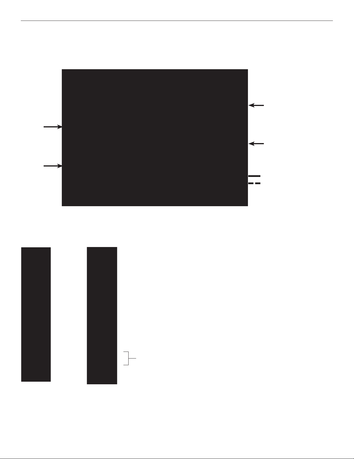
FIGURE 1 – CWFE1COAXM
COAX (75Ω)
CAT5e/6
FIGURE 2 – CWFE1COAXM
REAR PANELFRONT PANEL
BLACK
BLACK WITH WHITE STRIPE
Power Supply:
Surface Mount: 9–24VDC@120mA
NOTE: Remove Electrical
Connector for Rack Mount
Units
TECH SUPPORT: 1.888.678.9427
INS_CWFE(1,2)COAX[M]_REV–
11/18/10
PAGE 2
Page 3

INSTALLATION AND OPERATION MANUAL CWFE(1,2)COAX[M]
FIGURE 3 – CWFE1COAX
COAX (75Ω)
CAT5e/6
BLACK
BLACK WITH WHITE STRIPE
FIGURE 4 – CWFE1COAX
REAR PANELFRONT PANEL
Power Supply:
Surface Mount:
9 – 24 VDC @ < 120 mA OR
12 – 24 VAC @ < 120 mA
NOTE: Remove Electrical
Connector for Rack Mount
Units
NOTE: Remove Electrical Connector for Rack Mount Units
TECH SUPPORT: 1.888.678.9427
INS_CWFE(1,2)COAX[M]_REV–
11/18/10
PAGE 3
Page 4
INSTALLATION AND OPERATION MANUAL CWFE(1,2)COAX[M]
FIGURE 5 – CWFE2COAX
COAX (75Ω)
CAT5e/6
COAX (75Ω)
CAT5e/6
BLACK
BLACK WITH WHITE STRIPE
FIGURE 6 – CWFE1COAX
REAR PANELFRONT PANEL
Power Supply:
Surface Mount:
9 – 24 VDC @ < 120 mA OR
12 – 24 VAC @ < 120 mA
NOTE: Remove Electrical
Connector for Rack Mount
Units
NOTE: Remove Electrical Connector for Rack Mount Units
TECH SUPPORT: 1.888.678.9427
INS_CWFE(1,2)COAX[M]_REV–
11/18/10
PAGE 4
Page 5
INSTALLATION AND OPERATION MANUAL CWFE(1,2)COAX[M]
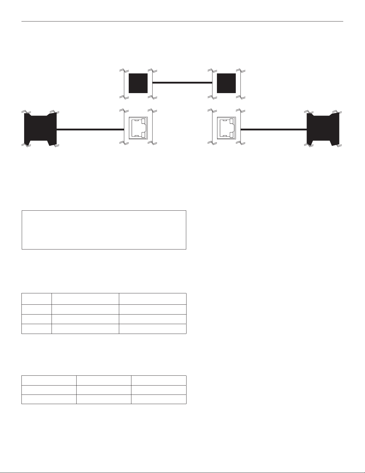
FIGURE 7 – POSSIBLE ETHERNET CONFIGURATIONS
Ethernet IEEE 802.3 Network Element determined by user.
Coaxial (75Ω)
CAT5e/6 with
RJ45 Connections
Ethernet IEEE 802.3
Network Element
CWFE1COAXM
(Master*)
FIGURE 8 – DISTANCE VS. SPEED
Line Side Port:
Coax connector: BNC
Impedance: 75 ohm coax
Throughput: (Down Stream / Up Stream)
< 1000 ft 100 Mbps / 100 Mbps
FIGURE 9 – LED INDICATORS
COAX LINK POWER
CWFE1COAXM
(Remote)
CAT5e/6 with
RJ45 Connections
Ethernet IEEE 802.3
Network Element
GREEN
OFF
BLINK
– Unit powered up
– Unit powered down
Coax data activity –
FIGURE 10 – SWITCH SETTINGS
SWITCH DOWN (ON) UP (OFF)
1 Remote Master
2 Remote Master
TECH SUPPORT: 1.888.678.9427
INS_CWFE(1,2)COAX[M]_REV–
11/18/10
PAGE 5
Page 6

MECHANICAL INSTALLATION INSTRUCTIONS
INSTALLATION CONSIDERATIONS
This modem is supplied as a Standalone module. Units should be installed
in dry locations protected from extremes of temperature and humidity.
CAUTION: Take care not to press on any of the LEDs.
WARNING: Unit is to be used with a Listed Class 2 or LPS power supply.
FIGURE A
Dimensions are for the CWFE1COAXM standalone ComNet module
IMPORTANT SAFEGUARDS:
A) Elevated Operating Ambient - If installed in a closed or multi-unit rack
assembly, the operating ambient temperature of the rack environment may
be greater than room ambient. Therefore, consideration should be given to
installing the equipment in an environment compatible with the maximum
ambient temperature (Tma) specified by the manufacturer.
B) Reduced Air Flow - Installation of the equipment in a rack should be such
that the amount of air flow required for safe operation of the equipment is not
compromised.
FIGURE B
Dimensions are for a standard ComNet™ one slot module
.156 [3.96 mm]
3 CORPORATE DRIVE | DANBURY, CT 06810 | USA
T: 203.796.5300 | F: 203.796.5303 | TECH SUPPORT: 1.888.678.9427 | INFO@COMNET.NET
8 TURNBERRY PARK ROAD | GILDERSOME | MORLEY | LEEDS, UK LS27 7LE
T: +44 (0)113 307 6400 | F: +44 (0)113 253 7462 | INFO-EUROPE@COMNET.NET
© 2012 Communications Networks Corp oration. All Rights Reserved. “ComNet” and the “ComNet Logo” are registere d trademarks of Communic ation Networks, LLC.
.313 [7.95 mm]
INS_CWFE(1,2)COAX[M]_REV–
11/18/10
PAGE 6
 Loading...