

Comnet CWFE1005POEMHO-M, CWFE1005POESHO-M, CWFE1003POESHO-M, CWFE1003POEMHO-M Installation And Operation Manual
Page 1
INSTALLATION AND OPERATION MANUAL
CWFE100(X)POE(M,S)-M
10/100 MBPS ETHERNET
2 PORT MEDIA CONVERTER
ELECTRICAL
SC/ST OPTICAL
1
WITH POWER OVER ETHERNET
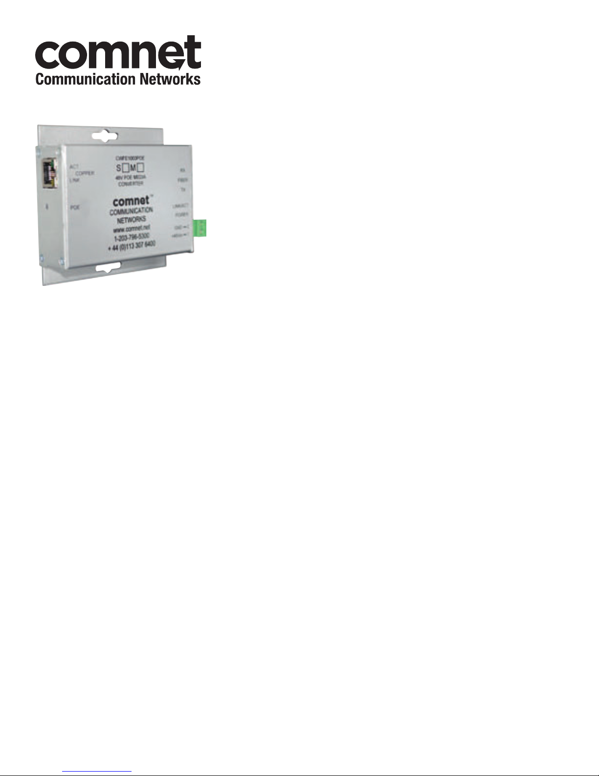
The ComNet™ CWFE1003POEM and CWFE1005POEM 2-port media converters provide
full-duplex fiber optic transmission of a single channel of 10/100 Mbps Ethernet data
(10/100 BASE-TX) through multimode or single mode optical fiber. Type SC or type
ST optical connectors are available, providing the user with the flexibility to use these
devices with virtually any multimode or single mode cable plant.
Both mode A and mode B of PoE operation are supported and selected by the media
converter automatically. The Ethernet electrical interface auto-negotiates to either
10 or 100 Mbps without the need for any user selection, and the optical interface
operates at 100 Mbps (100-FX).
LED indicators are provided for rapidly ascertaining the operating status of the
device. See Figure 9 on Page 6 for an explanation of the LED Indicators.
These units are designed for shelf or stand-alone mounting. See Figure A on
Page 7 for mounting instructions.
See Figures 1 – 11 for complete installation instructions.
INS_CWFE100(X)POE(M,S)-M_REV–
10/28/10
PAGE 1
Page 2
INSTALLATION AND OPERATION MANUAL CWFE100(X)POE(M,S)-M
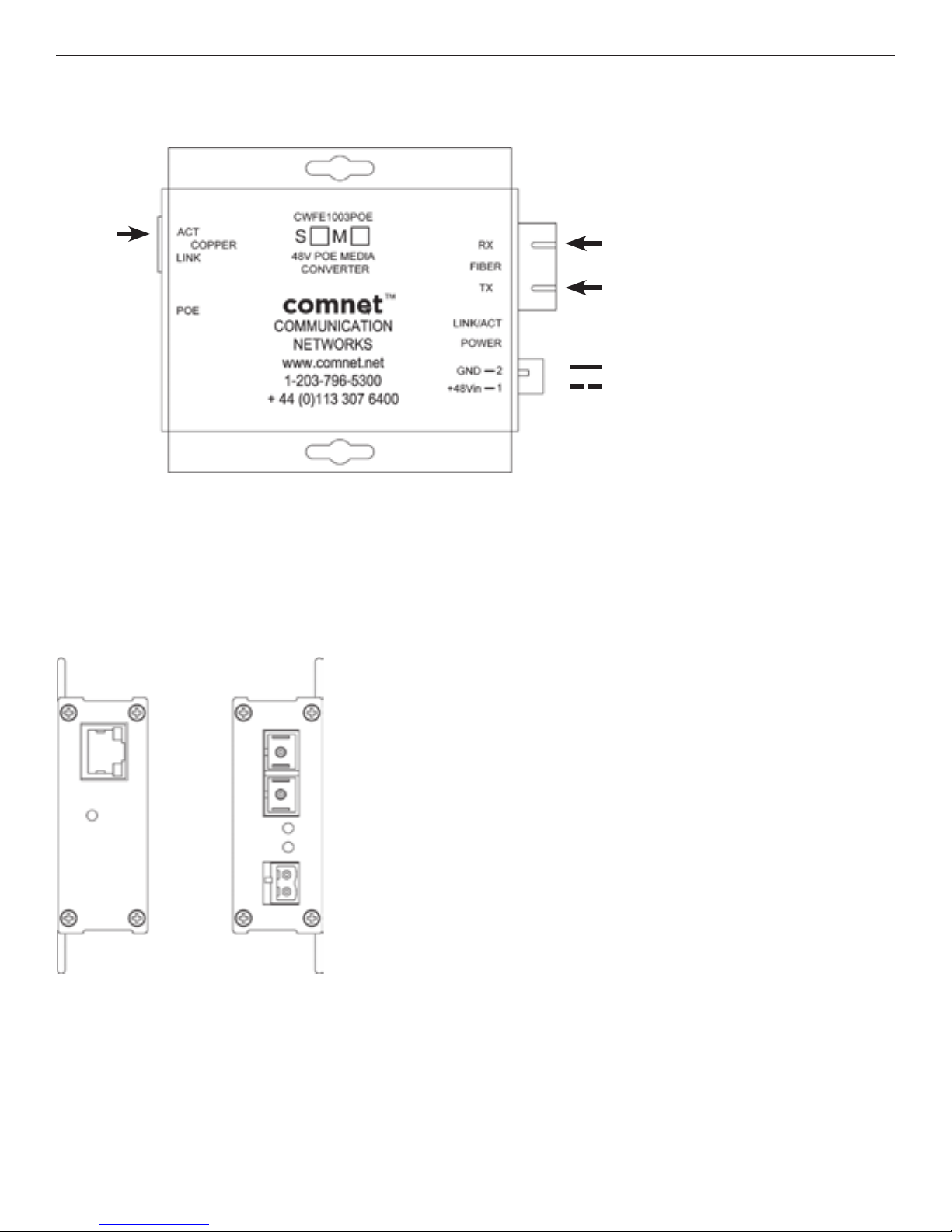
FIGURE 1 – CWFE1003POE(M,S)-M MEDIA CONVERTER
CAT5e/6
FIGURE 2 – CWFE1003POE(M,S)-M MEDIA CONVERTER
REAR PANELFRONT PANEL
MULTIMODE OR
SINGLE MODE
OPTICAL FIBER
BLACK
BLACK WITH WHITE STRIPE
TECH SUPPORT: 1.888.678.9427
INS_CWFE100(X)POE(M,S)-M_REV–
10/28/10
PAGE 2
Page 3

INSTALLATION AND OPERATION MANUAL CWFE100(X)POE(M,S)-M
FIGURE 2 – CWFE1003POE(M,S)HO-M MEDIA CONVERTER
CAT5e/6
FIGURE 3 – CWFE1003POE(M,S)HO-M MEDIA CONVERTER
REAR PANELFRONT PANEL
MULTIMODE OR
SINGLE MODE
OPTICAL FIBER
BLACK
BLACK WITH WHITE STRIPE
TECH SUPPORT: 1.888.678.9427
INS_CWFE100(X)POE(M,S)-M_REV–
10/28/10
PAGE 3
Page 4

INSTALLATION AND OPERATION MANUAL CWFE100(X)POE(M,S)-M
FIGURE 5 – CWFE1005POE(M,S)-M MEDIA CONVERTER
CAT5e/6
FIGURE 6 – CWFE1005POE(M,S)-M MEDIA CONVERTER
REAR PANELFRONT PANEL
MULTIMODE OR
SINGLE MODE
OPTICAL FIBER
BLACK
BLACK WITH WHITE STRIPE
TECH SUPPORT: 1.888.678.9427
INS_CWFE100(X)POE(M,S)-M_REV–
10/28/10
PAGE 4
Page 5

INSTALLATION AND OPERATION MANUAL CWFE100(X)POE(M,S)-M
FIGURE 7 – CWFE1005POE(M,S)HO-M MEDIA CONVERTER
CAT5e/6
FIGURE 8 – CWFE1005POE(M,S)HO-M MEDIA CONVERTER
REAR PANELFRONT PANEL
MULTIMODE OR
SINGLE MODE
OPTICAL FIBER
BLACK
BLACK WITH WHITE STRIPE
TECH SUPPORT: 1.888.678.9427
INS_CWFE100(X)POE(M,S)-M_REV–
10/28/10
PAGE 5
Page 6

INSTALLATION AND OPERATION MANUAL CWFE100(X)POE(M,S)-M
FIGURE 9 – LED INDICATORS
LINK/ACT POE POWER
GREEN
Fiber interface linked
(when lit or flashing)
OFF
Fiber interface not
linked.
FIGURE 10 – POSSIBLE ETHERNET CONFIGURATION
Ethernet IEEE 802.3 Network Element determined by user.
30W PoE
Power is being sup-
Unit powered up
plied by unit
Power not supplied
Unit powered down
by unit.
(No PoE device)
CWFE1003POEM-M CWFE1003POEM-M
CAT5e/6 with
RJ-45 Connections
Remote Ethernet
IEEE802.3at PD
FIGURE 11 – POE PIN ASSIGNMENT
RJ-45 port supports IEEE802.3at
End-point: Positive (VCC+): RJ45 pin 1, 2 or 4, 5
Negative (VCC-): RJ45 pin 3, 6 or 7,8
Data: (1, 2, 3, 6)
CAT5e/6 with
RJ-45 Connections
Ethernet IEEE 802.3
Network Element
2 Multimode
Optical Fibers
TECH SUPPORT: 1.888.678.9427
INS_CWFE100(X)POE(M,S)-M_REV–
10/28/10
PAGE 6
Page 7

MECHANICAL INSTALLATION INSTRUCTIONS
INSTALLATION CONSIDERATIONS
This unit is supplied as a Standalone module. Units should be installed in
dry locations protected from extremes of temperature and humidity.
WARNING: Unit is to be used with a Listed Class 2 or LPS power supply rated
48VDC @ 1A.
IMPORTANT SAFEGUARDS:
A) Elevated Operating Ambient - Consideration should be given to installing
the equipment in an environment compatible with the maximum ambient
temperature (Tma) specified by the manufacturer.
B) Reduced Air Flow - Installation of the equipment should be such that
the amount of air flow required for safe operation of the equipment is not
compromised.
FIGURE A
Dimensions are for a small size ComNet™ surface mount module
© 2011 Communicat ions Network s Corporation. All Rights Reserved. “ComNet ” and the “ComNet L ogo” are registered tr ademarks of Communication Networks, LLC.
3 CORPORATE DRIVE | DANBURY, CT 06810 | USA
T: 203.796.5300 | F: 203.796.5303 | TECH SUPPORT: 1.888.678.9427 | INFO@COMNET.NET
8 TURNBERRY PARK ROAD | GILDERSOME | MORLEY | LEEDS, UK LS27 7LE
T: +44 (0)113 307 6400 | F: +44 (0)113 253 7462 | INFO-EUROPE@COMNET.NET
INS_CWFE100(X)POE(M,S)-M_REV–
10/28/10
PAGE 7
 Loading...