

Page 1
INSTALLATION AND OPERATION MANUAL
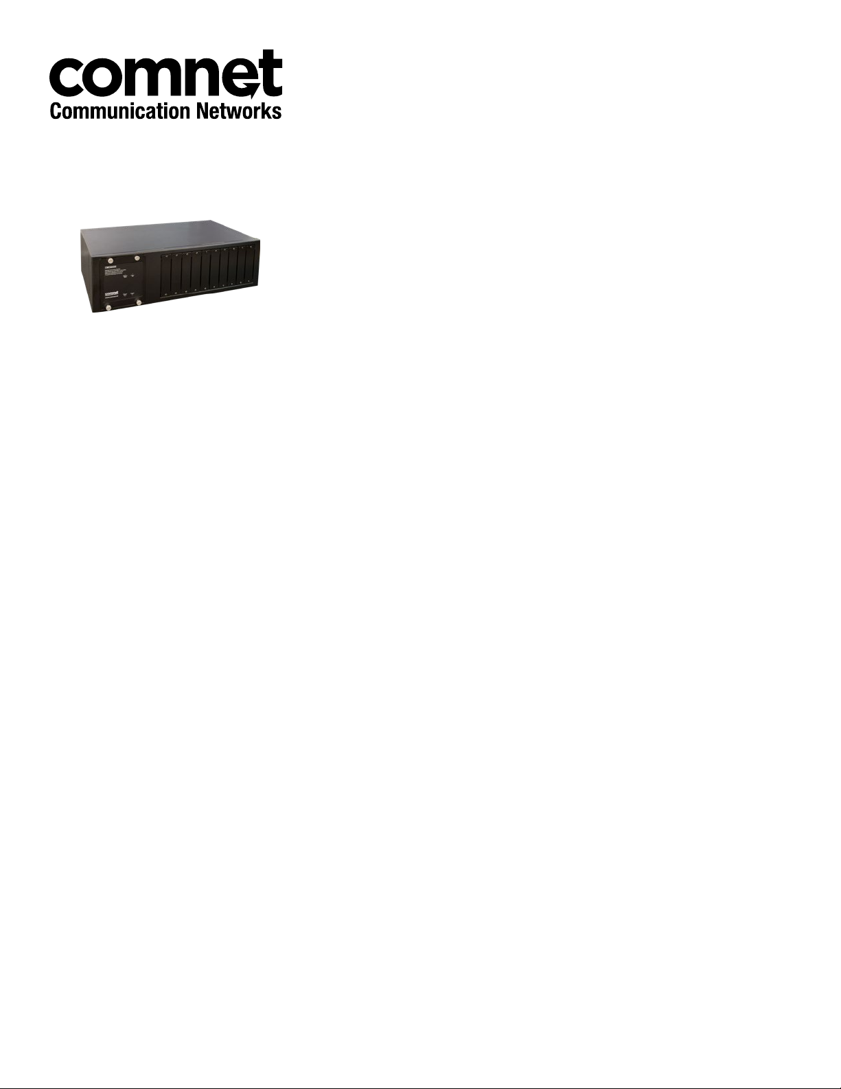
CWCHASSIS
Commercial Grade Media Converter Rack Mount Chassis
With Single or Dual Power Supplies
The CWCHASSIS is supplied with a single power supply but can also be fitted with a
second power supply (sold separately) that provides redundancy in the unlikely event of
a power supply failure. LED indicators provide visual indication in the event that one of
the two power supply modules has failed. The design approach employed by ComNet
for equipment mounted within the CWCHASSIS chassis rack unit with two modular
CWCHASSISPSU power supplies, provides for the elimination of a single-point failure
in the event of a major fault within any module located within the chassis rack. This is
accomplished through the use of automatic electronic current limiting within each rackmountable module, rather than providing the current limiting within the power supply
unit which supports the power requirements for equipment located within the rack. This
automatic current limiting feature is also self-resetting, should the fault or overload be
of a temporary or intermittent condition. Furthermore, all modules located within the
chassis rack are hot-swappable, so that it is not necessary to power-down the rack when
removing or replacing modules.
Rev. 12.4.17
Page 2

INSTRUCTION MANUAL CWCHASSIS
Contents
Package Contents 3
Hardware Description 3
Front Panel 3
Rear Panel 3
LED Indicators 4
Rack Mount Installation 5
Hardware Installation 5
Desktop Application 5
Rack Mounting 6
Media Converter Installation 7
TECH SUPPORT: 1.888.678.9427
INS_CWCHASSIS Rev. 12.4.17 PAGE 2
Page 3
INSTRUCTION MANUAL CWCHASSIS
Package Contents
» The CWCHASSIS 10 slot Rack Chassis
» Region-Specific Power cord
» Rubber feet
» Rack mount kit
» User manual
Compare the contents of your CWCHASSIS package with the standard checklist above. If any
item is missing or appears damaged, please keep the carton and original packaging materials if
possible in case you need to return the chassis for repair.
Hardware Description
This Chapter describes the hardware of the CWCHASSIS rack including Front panel, LEDs, and
Rear panel.
The CWCHASSIS rack is a modular unit, and its chassis contains 10 slots for optional media
converters.
The physical dimensions of the rack are: 440 × 266 × 133 mm
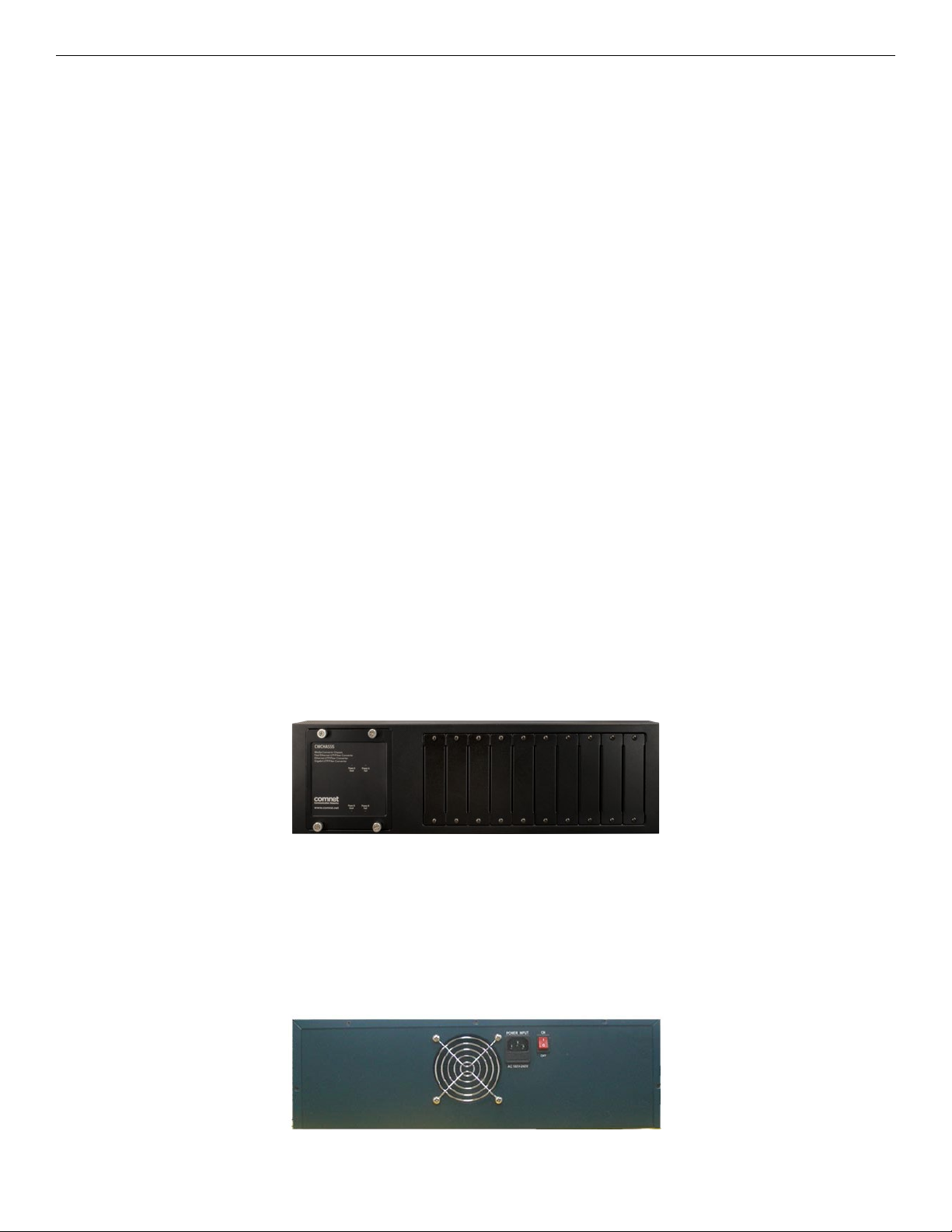
Front Panel
The Front Panel of The CWCHASSIS rack contains 10 slots for optional media converters and LEDs
to indicate dual redundant power supply status.
The Front Panel of the CWCHASSIS rack
Rear Panel
The IEC power plug, on/off switch and ventilation fan are located on the Rear Panel of the
CWCHASSIS rack displayed in below. The Chassis will work with AC in the range AC 100~240 VAC,
50/60 HZ. The redundant power slot is positioned behind the front panel of the CWCHASSIS rack.
TECH SUPPORT: 1.888.678.9427
The Rear Panel of the CWCHASSIS rack
INS_CWCHASSIS Rev. 12.4.17 PAGE 3
Page 4

INSTRUCTION MANUAL CWCHASSIS
LED Indicators
There are 4 diagnostic LEDs located on the Front panel of the CWCHASSIS rack. They provide
real-time information of system and operational status. The indicators include Power Good (A,
B) and Power Fail (A, B). The following table provides a description of the LED status and their
meanings.
LED Color Status Description
Power A Good Green Solid Power Module A is Ready
Off Power Module A is Not Ready
Power B Good Green On Power Module B is Ready
Off Power Module B is Not Ready
Power A Fail Orange On Power Module A is in Failure
Off Power Module A is Ready
Power B Fail Orange On Power Module B is in Failure
Off Power Module B is Ready
TECH SUPPORT: 1.888.678.9427
INS_CWCHASSIS Rev. 12.4.17 PAGE 4
Page 5

INSTRUCTION MANUAL CWCHASSIS
Rack Mount Installation
This Chapter provides the installation procedure of The CWCHASSIS rack.
Hardware Installation
The CWCHASSIS rack is suitable for use in an office environment where it can be rack-mounted in
standard EIA 19-inch racks or standalone.
Desktop Application
1. Set The CWCHASSIS on a sufficiently large flat space with a power outlet nearby.
2. Apply the rubber footpads to each corner on the bottom of the Chassis. These pads
cushion the switch against shock/vibration.
3. Connect the power cord. The power supply is self-adjusting for AC input power between
110 and 220 Volts.
Note: Air vents must not be blocked and must have free access to the room ambient air for
cooling.
TECH SUPPORT: 1.888.678.9427
INS_CWCHASSIS Rev. 12.4.17 PAGE 5
Page 6

INSTRUCTION MANUAL CWCHASSIS
Rack Mounting
To stack The CWCHASSIS rack in a standard 19-inch EIA rack, use the supplied mounting kit. This
kit contains 2 side-mounting brackets and 10 bracket screws.
Perform the following steps to rack mount the Chassis:
1. Position one bracket to align with the holes on one side of the switch and secure it with the
smaller bracket screws. Then attach the remaining bracket to the other side of the switch.
Attaching Mounting Brackets
2. After attached both mounting brackets, position the switch in the rack by lining up the
holes in the brackets with the appropriate holes on the rack. Secure the switch to the rack
with a screwdriver and the appropriate rack-mount screws (not supplied).
Rack Mount the Chassis
Note: For proper ventilation, allow about 6 inches of clearance on all sides of the Chassis. This is
especially important for enclosed rack installations.
TECH SUPPORT: 1.888.678.9427
INS_CWCHASSIS Rev. 12.4.17 PAGE 6
Page 7

INSTRUCTION MANUAL CWCHASSIS
Media Converter Installation
This Chapter provides the installation procedure of the sold separately CWFE2SC(M,S)2 and CWGE2SFP
series media converters within the CWCHASSIS rack.
1. Remove the slot blanking on the CWCHASSIS rack by unscrewing the two fixing screws using a
screwdriver. Put the blank panel aside, but don’t discard the blank panel in case it is required at a
later date.
2. Open the rack mount ear kit (10pcs are supplied with each CWCHASSIS). The kit contains two-rack
mount ears (with thumbscrew) and four screws. Do not discard any unused ear kits in case these are
required for additional media converter modules in the future.
3. Attach a rack mount ear on both sides of the media converter by using a screwdriver to secure the
rack mount ears.
4. Install the media converter by inserting it into the guides and sliding it in until it stops. Press it
firmly until the power plug in the chassis plugs into the media converter receptacle. Slide the media
converter in smoothly.
5. Gently push the thumbscrews in and turn clockwise to tighten. Do not over tighten the
thumbscrews.
TECH SUPPORT: 1.888.678.9427
INS_CWCHASSIS Rev. 12.4.17 PAGE 7
Page 8

MECHANICAL INSTALLATION INSTRUCTIONS
ComNet Customer Service
Customer Care is ComNet Technology’s global service center, where our professional staff is
ready to answer your questions at any time.
Email ComNet Global Service Center: customercare@comnet.net
3 CORPORATE DRIVE | DANBURY, CT 06810 | USA
T: 203.796.5300 | F: 203.796.5303 | TECH SUPPORT: 1.888.678.9427 | INFO@COMNET.NET
8 TURNBERRY PARK ROAD | GILDERSOME | MORLEY | LEEDS, UK LS27 7LE
T: +44 (0)113 307 6400 | F: +44 (0)113 253 7462 | INFO-EUROPE@COMNET.NET
© 2017 Communications Networks Corporation. All Right s Reserved. “ComNet” and the “ComNet Logo” are registered trademar ks of Communication Networks, LLC.
 Loading...