

Page 1

INSTALLATION AND OPERATION MANUAL
CN-OB(M,S)
INDUSTRIAL 2-PORT OPTICAL BYPASS SWITCH
WITH 4 × LC DUPLEX CONNECTORS
This manual serves the following
ComNet Model Numbers:
CN-OBM
CN-OBS
The ComNet CN-OB(M,S) is an external Bypass switch for 100M/1G/10G fiber optic
networks. This fiber optic bypass switch protects from network failures and Network
maintenance by ensuring network integrity during power loss. This fiber optic
bypass switch includes Network ports and Monitor ports. The Network ports are
used to connect to main-network connections and provide protection mechanism
and the Monitor ports are used for down-link local networking device. When the
power is on,the mode of the Bypass switch is in Normal operation mode and the
local networking device is connected with main-network. When on the power failure
state, the Bypass switch is set to bypass mode to isolate the main-network from the
local networking device.
INS_CN-OB(M,S)_REV– 3/18/16 PAGE 1TECH SUPPORT: 1.888.678.9427
Page 2
INSTALLATION AND OPERATION MANUAL CN-OB(M,S)
INSTALLATION AND OPERATION MANUAL CN-OB(M,S)
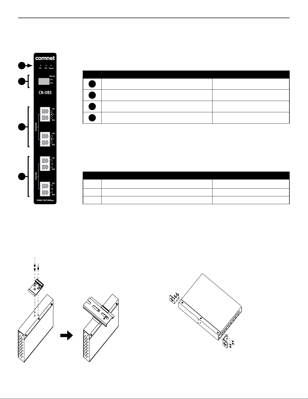
CN-OB(M,S) PHYSICAL DESCRIPTION
Figure 1 – Physical Features of CN-OB(M,S)
1
2
3
Table 1 – Physical Feature Descriptions
Call-out Description Manual Reference
1
Indicating LEDs See Table 2 - Indicator LEDs
2
DIP Switch Select for Power Alarm Relay Output See Table 3 - DIP Switch Operation
3
Network Fiber Ports See Figure 5 – Operation
4
Monitoring Fiber Ports See Figure 5 – Operation
Table 2 – Indicator LEDs
4
LED Description Color Indicator
P1 Power 1 Solid Green for Normal Operation
P2 Power 2 Solid Green for Normal Operation
Fault Fault Indicator Solid Amber for Power Failure
MOUNTING INSTRUCTIONS
Figure 2 – DIN Rail Mounting Kit Installation
TECH SUPPORT: 1.888.678.9427
Figure 3 – Wall Mount Bracket Installation
INS_CN-OB(M,S)_REV– 3/18/16 PAGE 2
Page 3

INSTALLATION AND OPERATION MANUAL CN-OB(M,S)
OPERATION INSTRUCTIONS
Figure 4 – Power Connections
PWR1
PWR21A@24V
-
+
Relay
+24V GND
Warning
Device
Power
Suppl y
V+ V-
DC12-48 V
V-
V+
Power 2
Suppl y
12-48 VDC
G
Power 1 Input 12-48 VDC
Fram eG roun d
Figure 5 – Operation
Normal Operation
The Bypass switch delivers
the data between the
Network ports and the
Monitor (local) ports
Normal mode Bypas sm od e
Table 3 – DIP Switch Settings
DIP Switch
1 2 Setting Effect
OFF OFF Power Failure Relay Alarm Disabled
ON OFF Power 1 Failure Relay Alarm Enabled
OFF ON Power 2 Failure Relay Alarm Enabled
ON ON Power 1 & Power 2 Failure Relay Alarms Enabled
P1 P2 Fault
Networ k
Monito r
100M/ 1G /10G bps
Bypass Mode
Network data traffic is
Alarm
P1
P2
routed directly to the other
Network port. Monitor data
traffic is routed directly to
the other Monitor port.
TX
A
RX
TX
B
RX
TX
A
RX
TX
B
RX
TECH SUPPORT: 1.888.678.9427
INS_CN-OB(M,S)_REV– 3/18/16 PAGE 3TECH SUPPORT: 1.888.678.9427
Page 4

INSTALLATION AND OPERATION MANUAL CN-OB(M,S)
INSTALLATION AND OPERATION MANUAL CN-OB(M,S)
INSTALLATION CONSIDERATIONS
These units are supplied as Standalone/DIN Rail mounted modules.
Units should be installed in dry locations protected from extremes of
temperature and humidity.
WARNING: Unit is to be used with a Listed Class 2 power supply.
IMPORTANT SAFEGUARDS:
A) Elevated Operating Ambient
assembly, the operating ambient temperature of the rack environment
may be greater than room ambient. Therefore, consideration should be
given to installing the equipment in an environment compatible with
the maximum ambient temperature (T
B) Reduced Air Flow - Installation of the equipment in a rack should be such
that the amount of air flow required for safe operation of the equipment
is not compromised.
- If installed in a closed or multi-unit rack
) specified by the manufacturer.
ma
3 CORPORATE DRIVE
8 TURNBERRY PARK ROAD
© 2016 Communicat ion Network s. All Rights R eserved. “C omNet,” the “Com Net Logo,” “Copper Line,” and the “Copp erLine Logo” ar e registered t rademarks o f Communication N etworks.
|
DANBURY, CONNECTICUT 06810
|
GILDERSOME
|
MORLEY
|
|
USA
T: 203.796.5300
|
LEEDS, UK LS27 7LE
|
F: 203.796.5303
|
T: +44 (0)113 307 6400
|
TECH SUPPORT: 1.888.678.9427
|
F: +44 (0)113 253 7462
|
INS_CN-OB(M,S)_REV– 3/18/16 PAGE 4
|
INFO@COMNET.NET
INFO-EUROPE@COMNET.NET
 Loading...