

Page 1
INSTALLATION AND OPERATION MANUAL
CNFE3FX1TX2C/M Series
CONTACT OVER ETHERNET MODULES
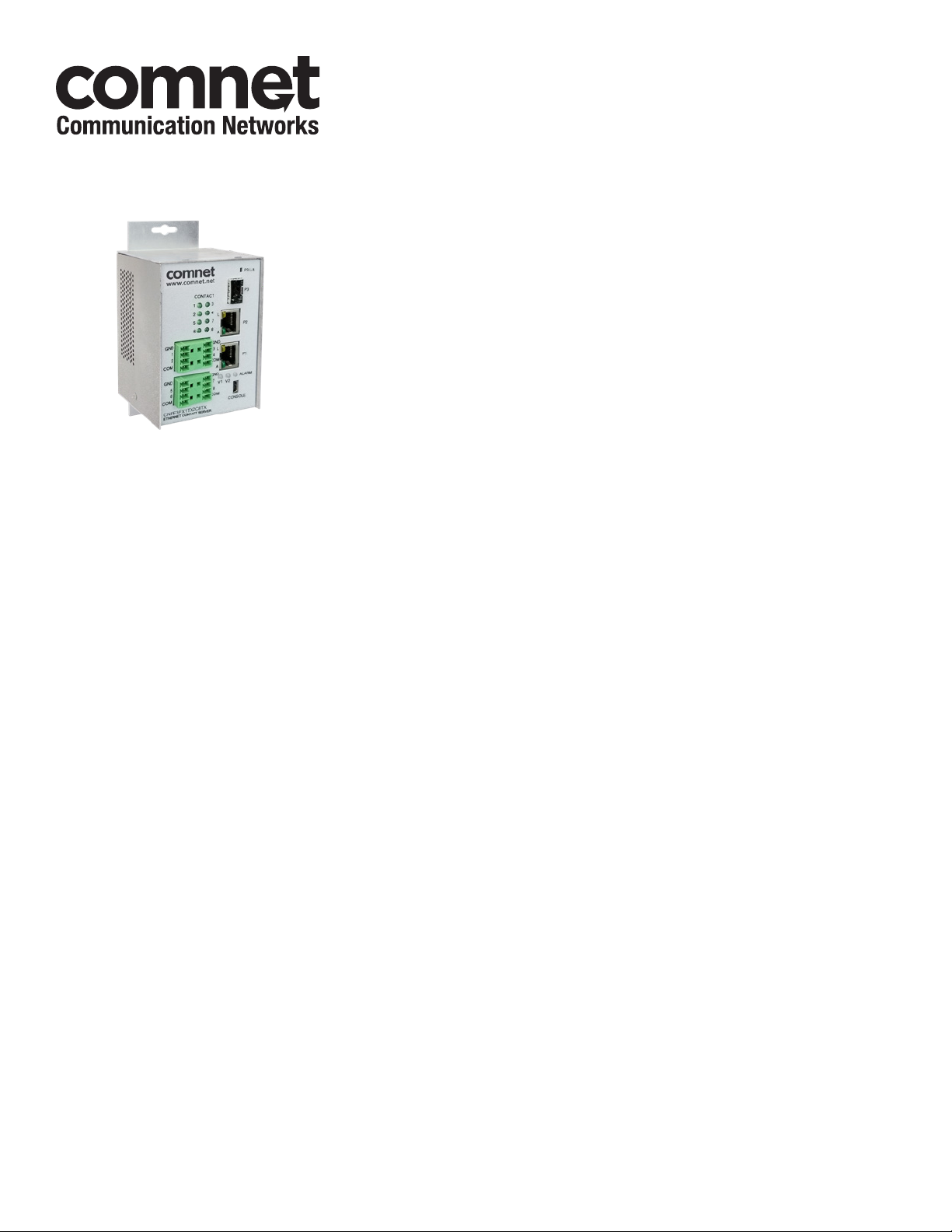
The ComNet CNFE3FX1TX2C/M series is an industrially hardened three-port intelligent
switch with light management functionality and an integrated contact closure
server. The 100BASE-FX port supports conventional CAT-5e/CAT-6 copper or optical
transmission media by selection of the appropriate ComNet SFP* module. A summary
fault alarm provides indication via a form c relay in the event of loss of optical link
or operating power. The 10/100BASE-TX ports support both auto-negotiation and
automatic MDI/MDI-X crossover for full and half-duplex operation; manual MDI/
MDI-X switching is not required. The integrated contact closure server is available
with 4 or 8 channels and supports individual user selectable wet or dry inputs. Form
A relay outputs feature individual user selection of normally open or normally closed
operation via the built-in web GUI. The contact server supports 4 modes of operation
including one-to-one, one-to-many, many-to-one and stand-alone.
The internal/self-contained 9 to 36 VDC or 24 VAC power supply features
redundant power inputs, for the highest possible reliability. The simple to install,
CNFE3FX1TX2C/M Series is DIN-rail or panel-mountable, and is ideal for missioncritical applications where very high levels of reliability and network availability are of
the utmost importance.
Page 2

INSTALLATION AND OPERATION MANUAL CNFE3FX1TX2C/M SERIES
Contents
Hardware description 3
Hardware Features 4
Module Input/Output Mapping 5
Software Features 6
Cables 7
Ethernet Cables 7
10/100BASE-T(X) Pin Assignments 7
Console Cable 8
SFP 8
WEB Management 9
Configuration by Web Browser 9
System Information 11
Switch Port Configuration 12
Active Ping Check Configuration 13
Authentication Username and Password Configuration 14
Firmware Upgrade 15
Factory Defaults 16
System Reset 17
Network Interface Configuration 18
SMNP 19
SNMP - Config 19
Alarm Contact 20
In Contact Ethernet Link 21
Out Contact Ethernet Link 22
Contact Status 23
Contact Configuration 23
Port Guardian 26
Command Line Interface Management 28
Firmware Upgrade Procedure 31
TECH SUPPORT: 1.888.678.9427
Static Multicast Routing Per Port 24
Static MAC Lock Configuration 25
INS_CNFE3FX1TX2C/M Series
10/11/11 PAGE 2
Page 3

INSTALLATION AND OPERATION MANUAL CNFE3FX1TX2C/M SERIES
Hardware description
The ComNet CNFE3FX1TX2C/M series is an industrially hardened three-port intelligent switch
with light management functionality and an integrated contact closure server. The 100BASE-FX
port supports conventional CAT-5e/CAT-6 copper or optical transmission media by selection of
the appropriate ComNet SFP module. A summary fault alarm provides indication via a form c relay
in the event of loss of optical link or operating power. The 10/100BASE-TX ports support both
auto-negotiation and automatic MDI/MDI-X crossover for full and half-duplex operation; manual
MDI/MDI-X switching is not required. The integrated contact closure server is available with 4 or 8
channels and supports individual user selectable wet or dry inputs. Form A relay outputs feature
individual user selection of normally open or normally closed operation via the built-in web GUI.
The contact server supports 4 modes of operation including one-to-one, one-to-many, many-toone and stand-alone.
Distances depend on which SFP (Small Form Pluggable) module is used. The two RJ45 Ethernet
connectors auto-negotiate or the configuration may be forced. The optical interface is fixed at
100Mbs.
TECH SUPPORT: 1.888.678.9427
INS_CNFE3FX1TX2C/M Series
10/11/11 PAGE 3
Page 4
INSTALLATION AND OPERATION MANUAL CNFE3FX1TX2C/M SERIES
Hardware Features
» 2 × Redundant DC power inputs
» Operating Temperature: -40 – 75ºC
» Storage Temperature: -40 – 85ºC
» Operating Humidity: 5% – 95%, non-condensing
» 2 × 10/100Base-T(X) Fast Ethernet port
» 1 × 100 Base-X SFP
» 4 × Dry Contact Inputs
» 4 × Form A Relays
» 1 × Form A Alarm Relay
» USB Console Port 115.2K baud 8N1
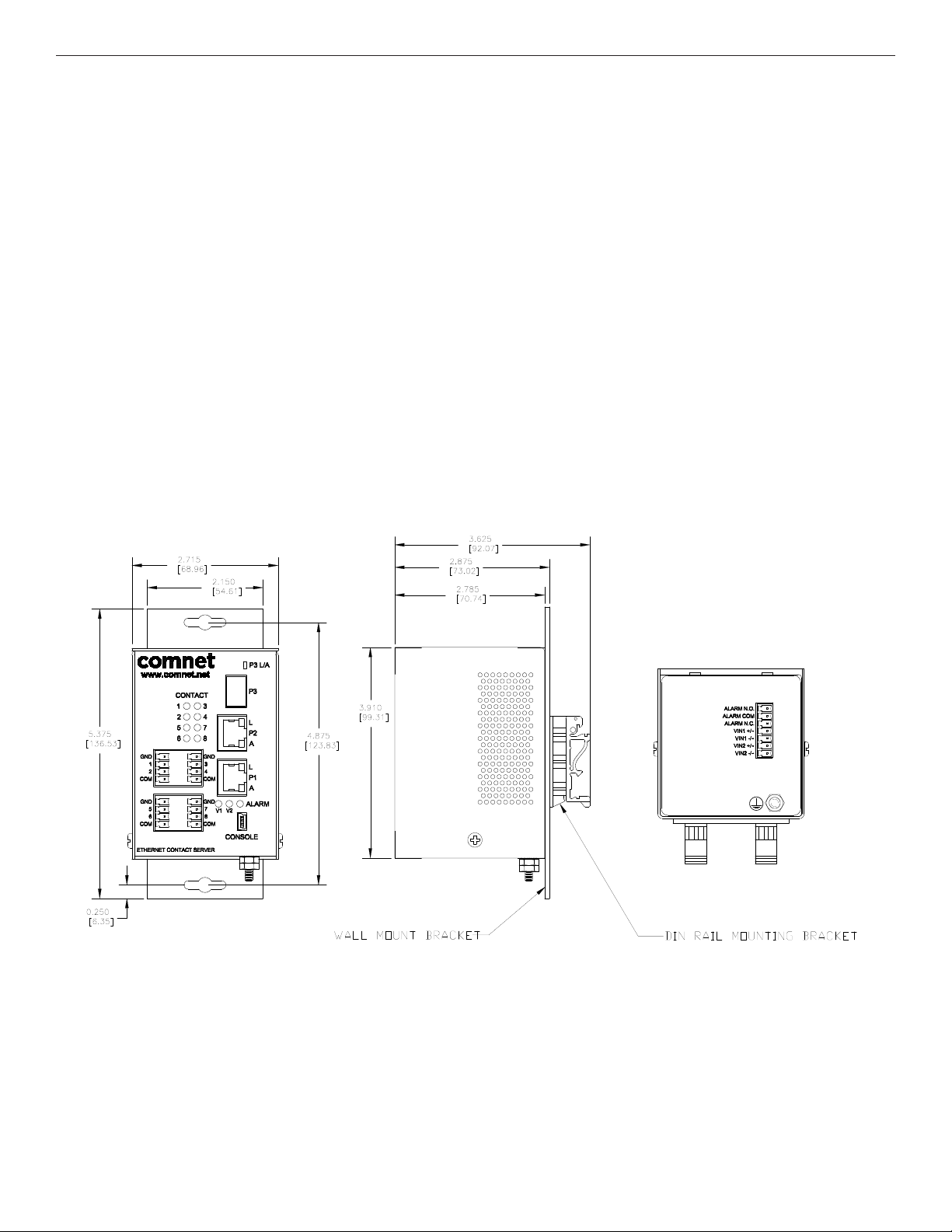
» Dimensions: w/ wall mount adapter plate 5.4 × 2.7 × 2.9 in (13.7 × 6.7 × 7.4 cm)
w/ DIN rail mount clips 3.9 × 2.7 × 3.6 in (9.9 × 6.7 × 9.1 cm)
Mechanical Drawing of CNFE8TCOE MODULE including contact connector pin-out
TECH SUPPORT: 1.888.678.9427
INS_CNFE3FX1TX2C/M Series
10/11/11 PAGE 4
Page 5

INSTALLATION AND OPERATION MANUAL CNFE3FX1TX2C/M SERIES
Module Input/Output Mapping
Module LEDs
LED Color Status Description
PWR1 Green On DC Power Input 1 Good
Off No power detected
PWR2 Green On DC Power Input 2 Good
Off No power detected
STATUS Green On Initialization passed
Red On Failed
10/100Base-T(X) Ethernet ports
LNK /ACT Green On Port link up
Blinking Data transmitting
100 Mbps
Amber On Port speed is 100 Mbps
indicator
SFP
LNK /ACT Green On Port link up
Blinking Data transmitted
TECH SUPPORT: 1.888.678.9427
INS_CNFE3FX1TX2C/M Series
10/11/11 PAGE 5
Page 6

INSTALLATION AND OPERATION MANUAL CNFE3FX1TX2C/M SERIES
Software Features
» Supports SNMPv1/v2c
» Event notification by SNMP trap and Alarm Relay Output
» Web-based GUI and USB Console CLI configuration
» Enable/disable ports
» IGMPv3 Multicast host
» Static MAC lock (per port)
» Static multicast MAC routing
» Field firmware upgrade capable
» Port Guardian physical port lockout feature
» Active ping check with SNMP trap & port shutdown capability
» Port Statistics
» Remote Reset
» Factory default reset
TECH SUPPORT: 1.888.678.9427
INS_CNFE3FX1TX2C/M Series
10/11/11 PAGE 6
Page 7

INSTALLATION AND OPERATION MANUAL CNFE3FX1TX2C/M SERIES
Cables
Ethernet Cables
The CNFE3FX1TX2C4DX switches have standard Ethernet ports. According to the link type, the
switches use CAT 3, 4, 5, & 5e UTP cables to connect to any other network device (PCs, servers,
switches, routers, or hubs). Please refer to the following table for cable specifications.
Cable Types and Specifications
Cable Type Max. Length Connector
10BA SE-T Cat. 3, 4, 5 100Ω UTP 100m (328ft) RJ-45
100BASE-TX Cat. 5 100Ω UTP UTP 100m (328ft) RJ-45
1000BASE-TX Cat. 5/Cat. 5e 100Ω UTP UTP 100m (328ft) RJ-45
10/100BASE-T(X) Pin Assignments
With 100BASE-T(X)/10BASE-T cable, pins 1 and 2 are used for transmitting data, and pins 3 and 6
are used for receiving data.
10/100 Base-T RJ-45 Pin Assignments
Pin Number Assignment
1 TD+
2 TD-
3 RD+
4 Not used
5 Not used
6 RD-
7 Not used
8 Not used
TECH SUPPORT: 1.888.678.9427
INS_CNFE3FX1TX2C/M Series
10/11/11 PAGE 7
Page 8
INSTALLATION AND OPERATION MANUAL CNFE3FX1TX2C/M SERIES
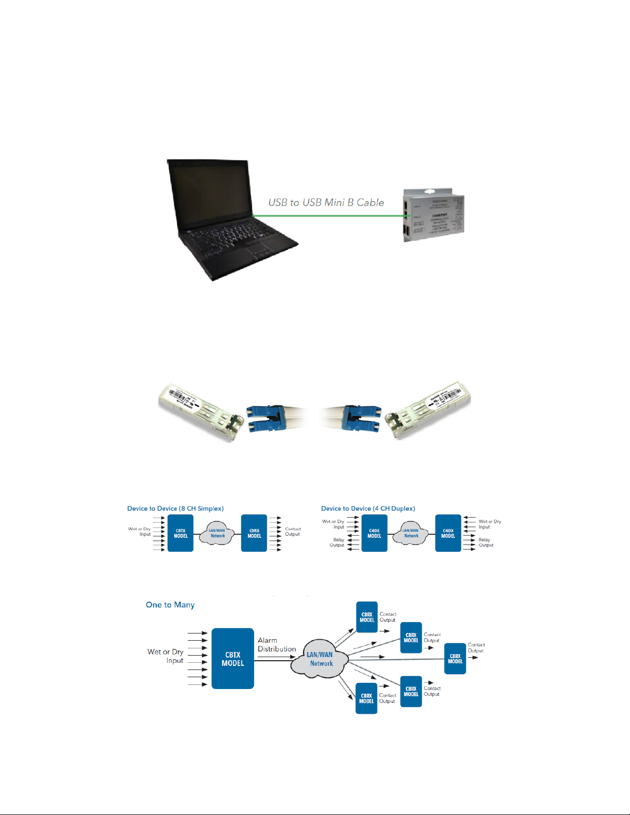
Console Cable
Each CNFE3FX1TX2C4DX switch can have the initial network settings configured by the
management console port. You can connect them to a PC with USB Ports using the supplied USB
to USB Mini B male plug cable.
SFP
The CNFE3FX1TX2C4DX has a fiber optic port that utilizes an SFP connector. ComNet offers a
wide selection of SFP modules that offer different fiber type, connector type and distances. Please
remember that the TX port of Switch A should be connected to the RX port of Switch B.
Application Examples
One to One UDP connection
One to Many Multicast UDP example
TECH SUPPORT: 1.888.678.9427
INS_CNFE3FX1TX2C/M Series
10/11/11 PAGE 8
Page 9

INSTALLATION AND OPERATION MANUAL CNFE3FX1TX2C/M SERIES
WEB Management
Attention: While installing and upgrading firmware, please DO NOT power off equipment while
the firmware is upgrading!
Configuration by Web Browser
This section provides instruction on configuration through the Web browser.
About Web-based Management
An embedded HTML web site resides in the flash memory on the CPU board. It contains
advanced management features and allows you to manage the switch from anywhere on the
network through a standard web browser such as Microsoft Internet Explorer.
The Web-Based Management function supports Internet Explorer 5.0 or later.
Preparing for Web Management
The default value is as below:
IP Address: 192.168.10.1 Subnet Mask: 255.255.255.0 Default Gateway: 192.168.10.254 User Name:
admin Password: admin
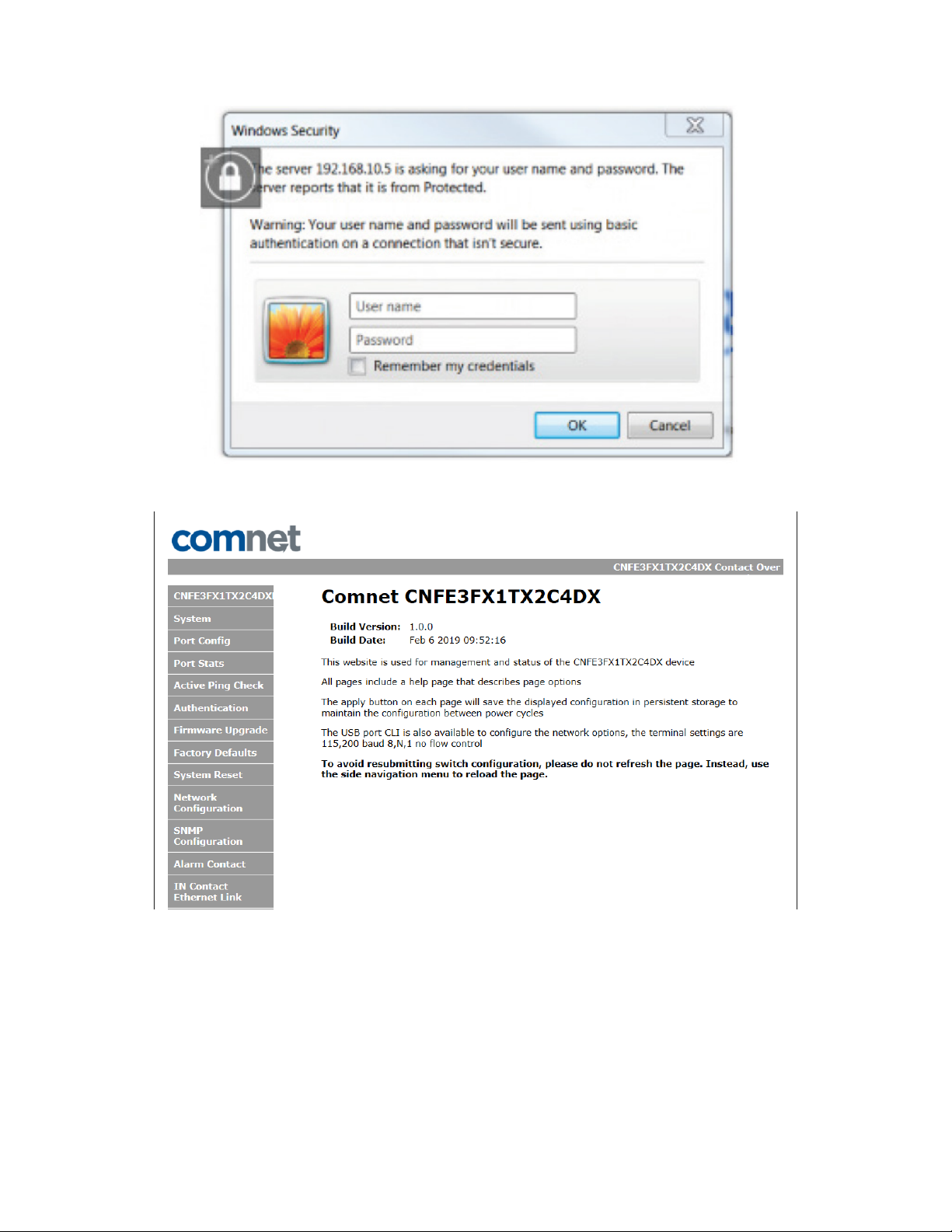
System Login
1. Launch your Web Browser.
2. Type http:// and the IP address of the switch. Press Enter.
3. The login screen appears.
4. Enter username and password. The default username and password is admin.
5. Select Enter or OK button, then the main interface of the Web-based management appears.
TECH SUPPORT: 1.888.678.9427
INS_CNFE3FX1TX2C/M Series
10/11/11 PAGE 9
Page 10
INSTALLATION AND OPERATION MANUAL CNFE3FX1TX2C/M SERIES
Main Index page
TECH SUPPORT: 1.888.678.9427
INS_CNFE3FX1TX2C/M Series
10/11/11 PAGE 10
Page 11

INSTALLATION AND OPERATION MANUAL CNFE3FX1TX2C/M SERIES
System Information
The switch system information is provided here
Label Description
Enabled protocols Summary table of enabled protocols
Temperature Unit’s internal board temperature reading
Port link status Link status and port disable
TECH SUPPORT: 1.888.678.9427
INS_CNFE3FX1TX2C/M Series
10/11/11 PAGE 11
Page 12

INSTALLATION AND OPERATION MANUAL CNFE3FX1TX2C/M SERIES
Switch Port Configuration
Unless you have reason to change this setting, it is recommended to leave the negotiation set to
auto. The link segment requires forcing the settings. Both ends of the link need to have the same
selection.
TECH SUPPORT: 1.888.678.9427
INS_CNFE3FX1TX2C/M Series
10/11/11 PAGE 12
Page 13

INSTALLATION AND OPERATION MANUAL CNFE3FX1TX2C/M SERIES
Active Ping Check Configuration
The active ping check function allows the switch to check that a configured IP address is alive
on each of the RJ45 ports. If the specified IP address becomes unreachable then the switch will
perform the action selected in the Failure Action menu.
Label Description
Enable Select to enable the active ping check function
Interval Active ping check interval in seconds
Remote IP Configure IP addresses of remote device to ping
Failure action Configure action to take upon failure
No Action - No action taken
SNMP Trap - Issue an SNMP trap
Power Down - Turn off the RJ45 port
PwrDwn & Trap - Issue an SNMP trap and then turn off the RJ45 port
Retries Number of times to retry the ping check on failure before proceeding with the
selected failure action.
TECH SUPPORT: 1.888.678.9427
INS_CNFE3FX1TX2C/M Series
10/11/11 PAGE 13
Page 14

INSTALLATION AND OPERATION MANUAL CNFE3FX1TX2C/M SERIES
Authentication Username and Password Configuration
The username and password entered here are also used in the CLI.
TECH SUPPORT: 1.888.678.9427
INS_CNFE3FX1TX2C/M Series
10/11/11 PAGE 14
Page 15

INSTALLATION AND OPERATION MANUAL CNFE3FX1TX2C/M SERIES
Firmware Upgrade
Upgrade Firmware allows you to update the firmware of the switch. Before updating, have your
Windows firmware update application ready and the firmware image is available. Many features
are not available during the firmware update process so please, observe the network topology
before upgrading.
Details on how to upload the new image is located in Firmware Upgrade section.
After applying a new firmware version, it is recommended that a Factory Default Reset is
performed to ensure that all new or adjusted settings take effect. Please note that performing a
Factory Default reset will erase all the devices settings except for the IP address.
Warning: Do not enable the firmware update process unless you have a firmware file available
and are ready to upgrade the unit. Once this processed is started it cannot be cancelled
and if a new firmware is not uploaded to the unit it will be necessary to return the unit
to the factory for re-programming.
TECH SUPPORT: 1.888.678.9427
INS_CNFE3FX1TX2C/M Series
10/11/11 PAGE 15
Page 16

INSTALLATION AND OPERATION MANUAL CNFE3FX1TX2C/M SERIES
Factory Defaults
This function restores the system configuration back to the factory default values. All parameters
will revert back to the original factory default values except the network configuration settings.
TECH SUPPORT: 1.888.678.9427
INS_CNFE3FX1TX2C/M Series
10/11/11 PAGE 16
Page 17

INSTALLATION AND OPERATION MANUAL CNFE3FX1TX2C/M SERIES
System Reset
This feature will perform a system reset.
Some system configuration changes require a system reset to take effect:
-File System updates
-Network configuration changes
- Static Mac Lock changes
- Static Mcast routing
After a system reset there may be a delay of up to 15 seconds before the device becomes
responsive again.
TECH SUPPORT: 1.888.678.9427
INS_CNFE3FX1TX2C/M Series
10/11/11 PAGE 17
Page 18

INSTALLATION AND OPERATION MANUAL CNFE3FX1TX2C/M SERIES
Network Interface Configuration
Label Description
Host Name Assign a name to the device (this is used for CLI and SNMP functions)
Enable DHCP To enable or disable the DHCP client function. When DHCP client function is
enabled, the switch will be assigned the IP address from the network DHCP
server. The default IP address will be replaced by the IP address which the
DHCP server has assigned.
IP Address Assign the IP address that the switch will use. If DHCP client Function is
enabled, you do not need to assign the IP address.
Gateway Assign the network gateway for the switch.
Subnet MaskPrimary DNS Assign the subnet mask for the switch.
Primary DNS Assign the primary DNS IP address
Secondary DNS Assign the secondary DNS IP address
Apply Select Apply to set the configurations.
Note: A system reset must be performed after making changes to the network settings.
TECH SUPPORT: 1.888.678.9427
INS_CNFE3FX1TX2C/M Series
10/11/11 PAGE 18
Page 19

INSTALLATION AND OPERATION MANUAL CNFE3FX1TX2C/M SERIES
SMNP
Simple Network Management Protocol (SNMP) is the protocol developed to manage nodes
(servers, workstations, routers, switches and hubs etc.) on an IP network. SNMP enables network
administrators to manage network performance, find and solve network problems, and plan for
network growth. Network management systems learn of problems by receiving traps or change
notices from network devices implementing SNMP.
SNMP - Config
Label Description
SNMP V1/V2c
Community
SNMP trap enable Enable SNMP traps to be sent to the manager
Manager IP address IP address of the management software
Apply Select Apply to activate the configurations.
Help Show help file.
TECH SUPPORT: 1.888.678.9427
The switch supports one Read and one Write SNMP community string. Community
string names are limited to 8 characters. To disable a community string leave its
entry blank.
INS_CNFE3FX1TX2C/M Series
10/11/11 PAGE 19
Page 20

INSTALLATION AND OPERATION MANUAL CNFE3FX1TX2C/M SERIES
Alarm Contact
CNFE3FX1TX2C4DX Contact Configuration, allows for the setting of what happens when specific
instances occur during the operation of the unit allowing for the triggering of the alarm contact.
CNFE3FX1TX2C4DX Contact Override, allows for the override and force setting of the alarm
contact for testing and troubleshooting purposes.
CNFE3FX1TX2C4DX Contact Status shows the current status of the output of the alarm contact.
TECH SUPPORT: 1.888.678.9427
INS_CNFE3FX1TX2C/M Series
10/11/11 PAGE 20
Page 21

INSTALLATION AND OPERATION MANUAL CNFE3FX1TX2C/M SERIES
In Contact Ethernet Link
Allows for enabling a link between Input Contacts on a Host device to Output Contacts on a
Remote device(s). Device’s input contacts can be configured either One to One, or One to Many.
One to One:
Enabling this option, the Remote Output IP must match the IP Address of the device you wish
to communicate with. This is also true for the Port Number. As well as enabling the One to One
option the desired input contacts must be selected from the Selected Input Contacts section.
One to Many:
Enabling this option, allows for the use of multicasting the contacts between a group of devices
within the same multicast group. For this work the Multicast Group and Port Number must match
the same Multicast Group and Port Number as the Output Contact Configuration. As well as
enabling the One to Many option the desired input contacts must be selected from the Selected
Input Contacts section.
Selected Input Contacts:
These check boxes allow for the enabling and disabling of the input contacts on the Host device.
TECH SUPPORT: 1.888.678.9427
INS_CNFE3FX1TX2C/M Series
10/11/11 PAGE 21
Page 22

INSTALLATION AND OPERATION MANUAL CNFE3FX1TX2C/M SERIES
Out Contact Ethernet Link
Allows for enabling a link between a remote Input Contact device(s) and the local output contacts.
Device’s output contacts can be configured either One to One, or One to Many.
One to One:
Enabling this option, the Remote Output IP must match the IP Address of the device you wish to
communicate with. This is also true for the Port Number.
One to Many:
Enabling this option, allows for the use of multicasting the contacts between a group of devices
within the same multicast group. For this work the Multicast Group and Port Number must match
the same Multicast Group and Port Number as the Input Contact Configuration.
Retain Remote Data:
Enabling this option allows for the retention of the last data state when a link is lost and will hold
until a new link is enabled.
TECH SUPPORT: 1.888.678.9427
INS_CNFE3FX1TX2C/M Series
10/11/11 PAGE 22
Page 23

INSTALLATION AND OPERATION MANUAL CNFE3FX1TX2C/M SERIES
Contact Status
Allows for a display of the current overview of the current states for the input and output contacts.
Contact Configuration
Contact Configuration allows for the configuration of each port for both input and output to
trigger SMNP Traps.
INS_CNFE3FX1TX2C/M Series
TECH SUPPORT: 1.888.678.9427
10/11/11 PAGE 23
Page 24

INSTALLATION AND OPERATION MANUAL CNFE3FX1TX2C/M SERIES
Static Multicast Routing Per Port
Label Description
Enable Enable static multicast MAC routing
MAC Addr. Destination Multicast MAC address of the stream
Port Number Ports to be included in the multicast route
Apply Select Apply to activate the configurations.
Help Show help file.
Note: A system reset must be performed after making changes to the MAC routing settings.
TECH SUPPORT: 1.888.678.9427
INS_CNFE3FX1TX2C/M Series
10/11/11 PAGE 24
Page 25

INSTALLATION AND OPERATION MANUAL CNFE3FX1TX2C/M SERIES
Static MAC Lock Configuration
Label Description
Enable Enable static MAC locking
MAC Addr. MAC address of the device that is allowed to forward and receive traffic. Packets will be
dropped for MAC addresses not listed in the table stream
Port Number Ports to be included in the locked list
Apply Select Apply to activate the configurations.
Help Show help file.
Note: A system reset must be performed after making changes to the static MAC lock settings.
TECH SUPPORT: 1.888.678.9427
INS_CNFE3FX1TX2C/M Series
10/11/11 PAGE 25
Page 26

INSTALLATION AND OPERATION MANUAL CNFE3FX1TX2C/M SERIES
Port Guardian
The Port Guardian feature provides a high security managed port lock out mode and when
enabled will power down the port as soon as a link loss status is detected when a cable is
disconnected. This provides high security against network attack by an intruder who accesses
the edge device and disconnects it to then try and connect their own intrusion device (laptop,
network sniffer etc.).
To reset a port from a lock out state the network administrator can issue an SNMP reset or can
reset a port by using the CLI via the USB serial port. In PoE models a reset can also be initiated by
using one of the contact inputs.
TECH SUPPORT: 1.888.678.9427
INS_CNFE3FX1TX2C/M Series
10/11/11 PAGE 26
Page 27

INSTALLATION AND OPERATION MANUAL CNFE3FX1TX2C/M SERIES
Port Guardian – CLI Reset
Command Description
portguardian show Will display any ports that are currently in port lockout fault state.
Command Description
portguardian clear Will clear any ports that were previously in port lockout fault state.
TECH SUPPORT: 1.888.678.9427
INS_CNFE3FX1TX2C/M Series
10/11/11 PAGE 27
Page 28

INSTALLATION AND OPERATION MANUAL CNFE3FX1TX2C/M SERIES
Command Line Interface Management
Configuration by Command Line Interface (CLI).
About CLI Management
Besides WEB-base management, the CNGE4+2SMS also supports CLI management for network
configuration. You can use USB console to manage the switch by CLI.
CLI Management by USB Console (115200, 8, none, 1, none)
Before configuring by USB console, use a USB mini B cable to connect the switch’s Console port
to your PC’s USB port.
Follow the steps below to access the console via USB mini B cable.
Step 1. Connect the USB cable between the PC and the CNGE4+2SMS. If the device driver is not
found, the product CD includes the windows .inf driver.
Step 2. From the Windows desktop, select on Start -> Tera Term
TECH SUPPORT: 1.888.678.9427
INS_CNFE3FX1TX2C/M Series
10/11/11 PAGE 28
Page 29

INSTALLATION AND OPERATION MANUAL CNFE3FX1TX2C/M SERIES
Step 3. Select the COM port number
Step 4. The COM port properties setting, 115200 for Bits per second, 8 for Data bits, None for
Parity, 1 for Stop bits and none for Flow control.
TECH SUPPORT: 1.888.678.9427
INS_CNFE3FX1TX2C/M Series
10/11/11 PAGE 29
Page 30

INSTALLATION AND OPERATION MANUAL CNFE3FX1TX2C/M SERIES
Step 5. Hit enter to initiate the connection and receive the username prompt. After entering the
username and password the console will be presented with a CLI prompt.
Enter “?” or “help” to list the commands
More detailed help for each command is available using help in front of the command name.
TECH SUPPORT: 1.888.678.9427
INS_CNFE3FX1TX2C/M Series
10/11/11 PAGE 30
Page 31

INSTALLATION AND OPERATION MANUAL CNFE3FX1TX2C/M SERIES
Issuing a “netinfo” command will display the ip address of the switch
To change the network configuration using the CLI, the following commands must be used:
-setip
-setgw
-setdns
Save_netcfg if you want to save these changes in the startup configuration. Not using this
command will not save the changes persistently.
Firmware Upgrade Procedure
The steps for upgrading the unit with the push boot loader are as follows;
1. Bring up the web server and open the FileSystem Upload page click the Enable Image upload
check box and hit apply.
2. Open the Windows bootloader application, click the enable Ethernet check box and adjust the
IP address to the target IP
3. Click the “Load Hex File” and select the new firmware file. - Click Erase - Click Program - Click
Verify - Click run application Note: The “Erase-Program-Verify” button is not supported at this
time. Please use the individual buttons.
Warning: Do not enable the firmware update process unless you have a firmware file available
and are ready to upgrade the unit. Once this processed is started it cannot be cancelled
and if a new firmware is not uploaded to the unit it will be necessary to return the unit
to the factory for re-programming.
INS_CNFE3FX1TX2C/M Series
TECH SUPPORT: 1.888.678.9427
10/11/11 PAGE 31
Page 32

INSTALLATION AND OPERATION MANUAL CNFE3FX1TX2C/M SERIES
TECH SUPPORT: 1.888.678.9427
INS_CNFE3FX1TX2C/M Series
10/11/11 PAGE 32
Page 33

MECHANICAL INSTALLATION INSTRUCTIONS
ComNet Customer Service
Customer Care is ComNet Technology’s global service center, where our
professional staff is ready to answer your questions at any time.
Email ComNet Global Service Center: customercare@comnet.net
3 CORPORATE DRIVE | DANBURY, CT 06810 | USA
T: 203.796.5300 | F: 203.796.5303 | TECH SUPPORT: 1.888.678.9427 | INFO@COMNET.NET
8 TURNBERRY PARK ROAD | GILDERSOME | MORLEY | LEEDS, UK LS27 7LE
T: +44 (0)113 307 6400 | F: +44 (0)113 253 7462 | INFO-EUROPE@COMNET.NET
© 2019 Communications Networks Corpor ation. All Right s Reserved. “ComNet” and the “ComNet Logo” are registered trademarks of Communication Networ ks, LLC.
 Loading...