

Page 1
INSTALLATION AND OPERATION MANUAL
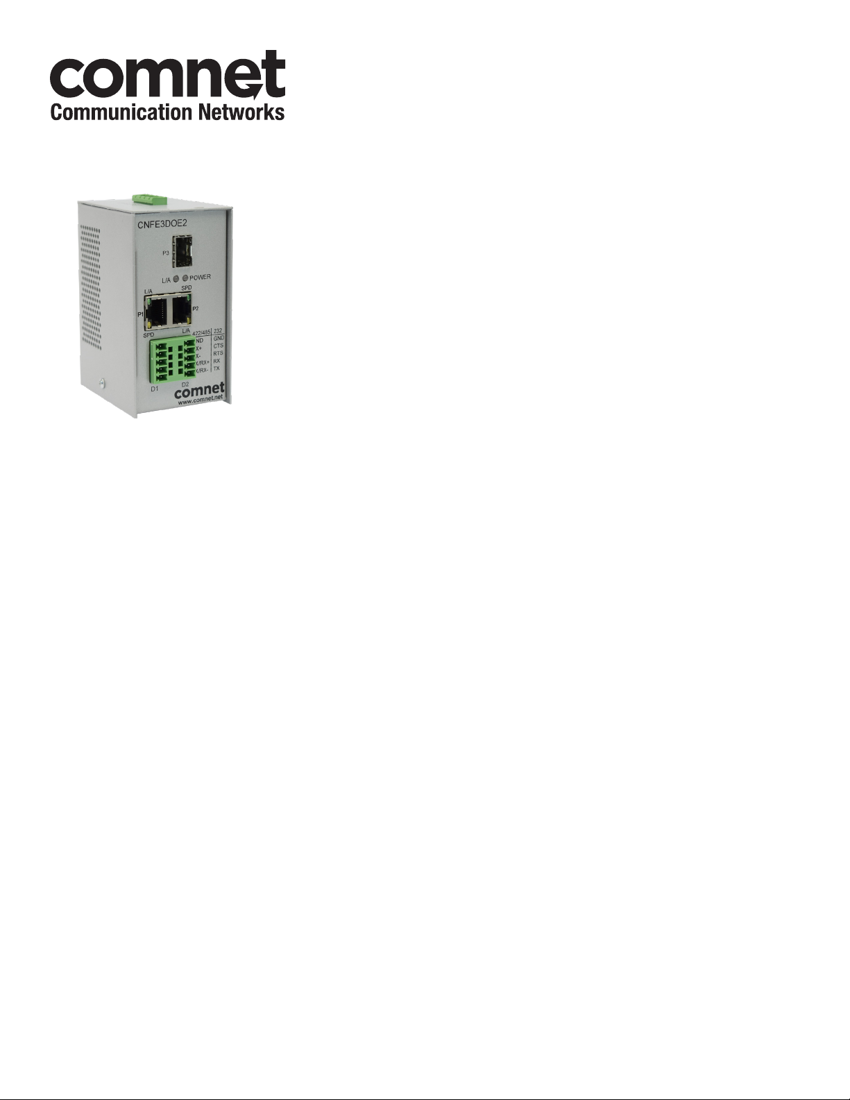
CNFE3DOE2/M
RS232/422/485 DATA OVER ETHERNET TERMINAL SERVER
The ComNet CNFE3DOE2/M allows any combination of two RS-232, RS-422, or 2 or
4-wire RS-485 serial data circuits to be inserted onto any 10/100 Mbps Ethernet-based
network. The CNFE3DOE2/M units include two serial data input/output ports, and
three Ethernet ports featuring two electrical ports and one SFP port. It may be used to
tunnel serial data over an IP network or as a media converter, for converting copper
transmission media to fiber. Access one serial device from the Internet and another
serial device from a local area network (LAN) using SSH or SSL. The CNFE3DOE2/M
provides control of the remote hardware, as if it were connected directly to the PC
COM port. A USB to serial converter may be required in new PCs without a DB9 serial
connection. The CNFE3DOE2/M supports SNMP Version 1, RFC1155, RFC1213 &
RFC1215.
Page 2

INSTALLATION AND OPERATION MANUAL CNFE3DOE2/M
Contents
Hardware description 3
Assign IP Address to a Terminal Server 4
Using Terminal Server as a Serial Extender over Ethernet 8
TCP Transport 8
UDP Transport 13
SSL Transport 17
Creating openssl certificates 24
SSH Transport 26
Creating SSH key pairs 30
Telnet Transport 30
HTTPS Configuration 34
OpenSSL Certificate, key and CA for HTTPS 40
Console Port Access 41
Network Statistics 42
Factory Defaults 43
Upgrading Firmware 44
Module Update 44
TECH SUPPORT: 1.888.678.9427
INS_CNFE3DOE2/M
10/11/11 PAGE 2
Page 3
INSTALLATION AND OPERATION MANUAL CNFE3DOE2/M
Hardware description
The ComNet CNFE3DOE2/M terminal server supports Ethernet transmission over two copper
ports and one fiber port. The server is universally compatible with RS232, RS422, RS485 serial
data protocols. All configurations are done through its web server. Distances depend on which
SFP (Small Form Pluggable) module is used. The RJ45 Ethernet and SFP interfaces are all enabled.
They can function as an Ethernet media converter.
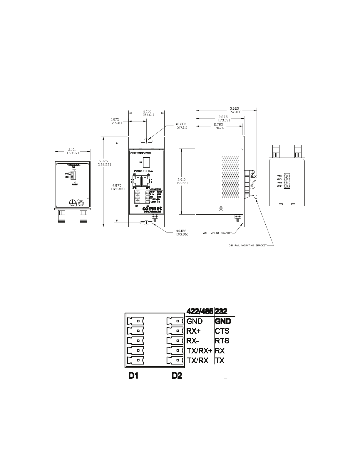
Mechanical Drawing of CNFE3DOE2/M Unit
Switches are used for RS485 Full Duplex mode to terminate Tx+ & Tx- and Rx+ & Rx- with 120
ohms. Both switches should be in the on position. For all other modes, the switches should be in
the off position.
The data connector pin-out is as below:
Settings by Data Type (Port 1 or 2)
TECH SUPPORT: 1.888.678.9427
INS_CNFE3DOE2/M
10/11/11 PAGE 3
Page 4
INSTALLATION AND OPERATION MANUAL CNFE3DOE2/M
Assign IP Address to a Terminal Server
A unique IP address has to be assigned to each terminal server device. You can connect one
at a time to change the default IP address. The default IP address of the device is the same:
192 .168.10.1.
Connect the terminal server on to your local Ethernet network which your PC is connected to, and
power on the unit.
Follow the steps below to set up your PC IP address to the same subnet as the terminal servers.
Disable the machine’s wireless network connection and any other internet connections that could
interfere with the network being created.
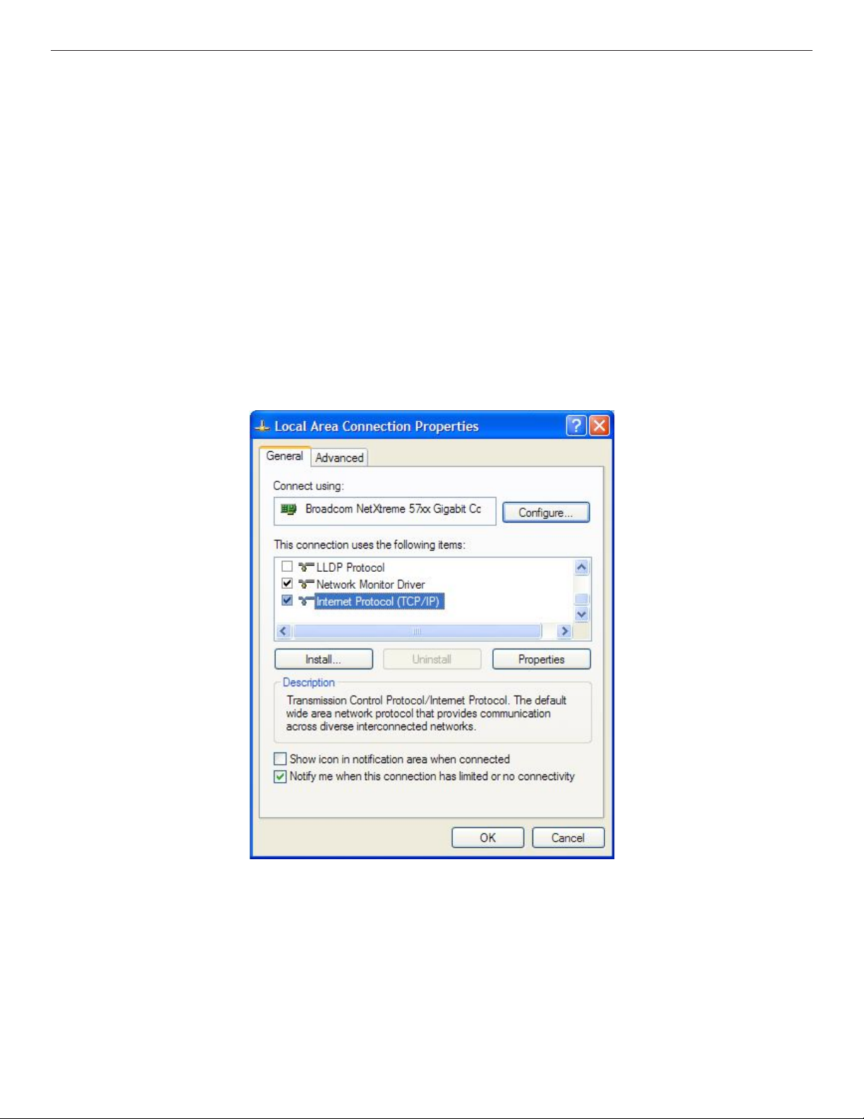
Select the Internet Protocol (TCP/IP) connection within the Local Area Connection Properties from
start -> Control Panel -> Network Connections -> Properties.
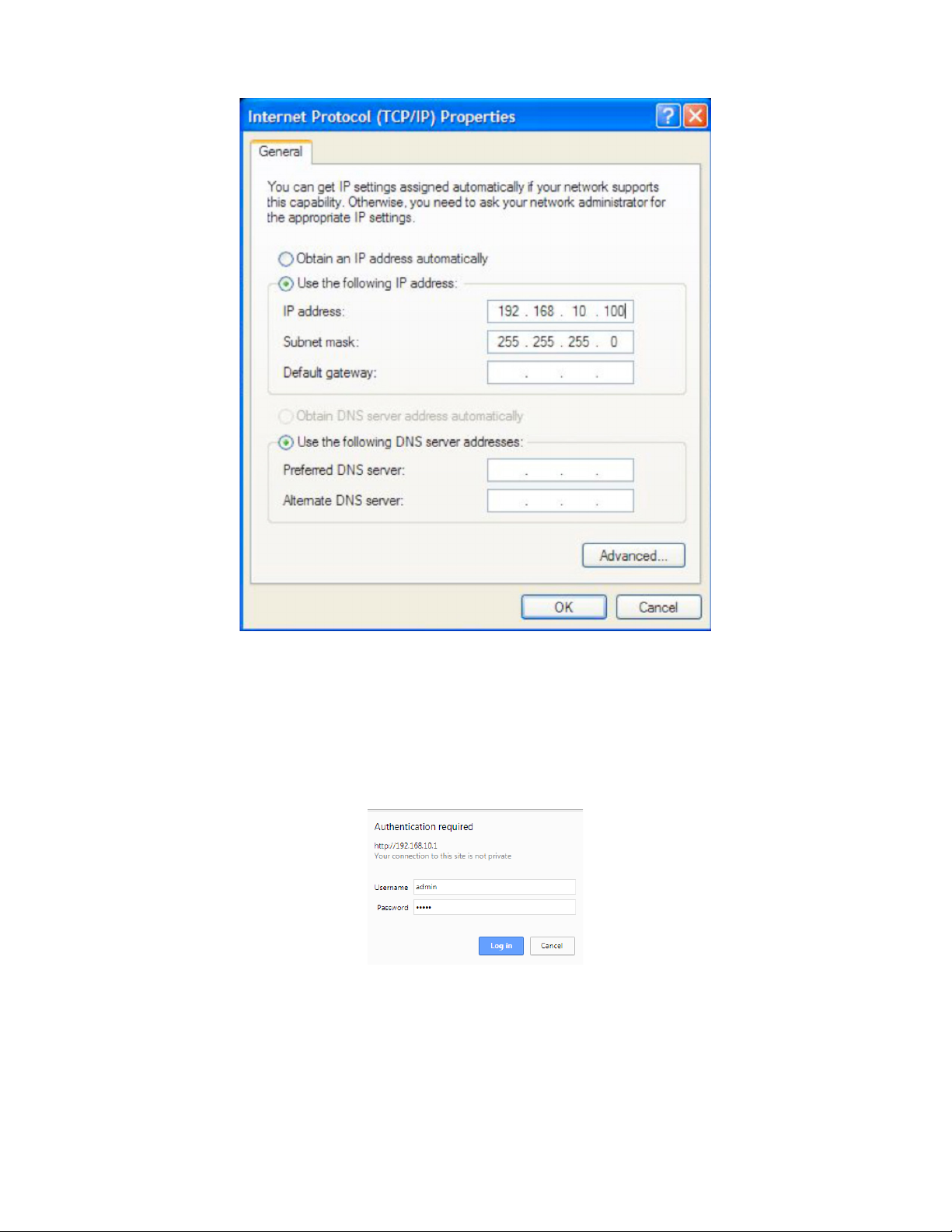
Next, manually set your IP address to 192 .168.10.100, for instance, and your subnet mask to
255.255.255.0, as shown below.
INS_CNFE3DOE2/M
TECH SUPPORT: 1.888.678.9427
10/11/11 PAGE 4
Page 5
INSTALLATION AND OPERATION MANUAL CNFE3DOE2/M
Click OK to finish the setting.
Open the browser on your PC, and type in 19 2.168 .10.1 and open the Terminal Server Log in Page
as shown.
The default User Name and Password are both admin
Log in to the Terminal Server Home Page as shown.
Terminal Server Log in Pop-up
TECH SUPPORT: 1.888.678.9427
INS_CNFE3DOE2/M
10/11/11 PAGE 5
Page 6
INSTALLATION AND OPERATION MANUAL CNFE3DOE2/M
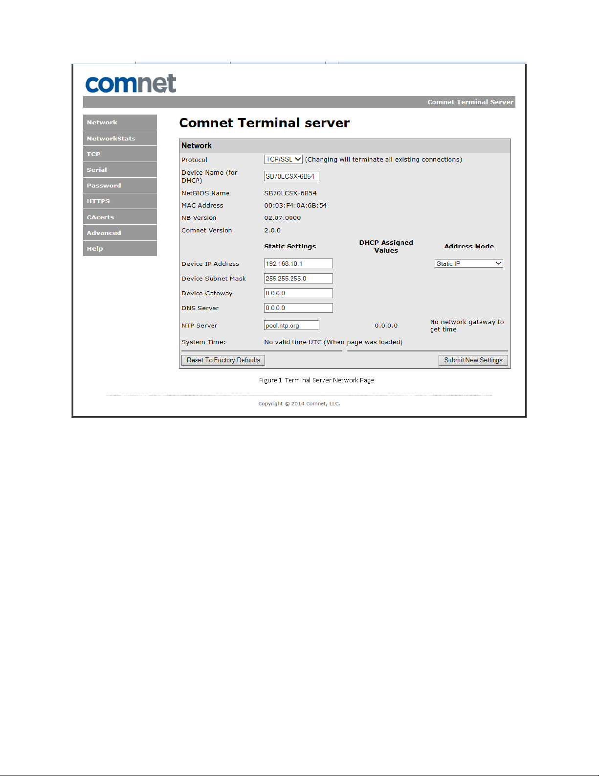
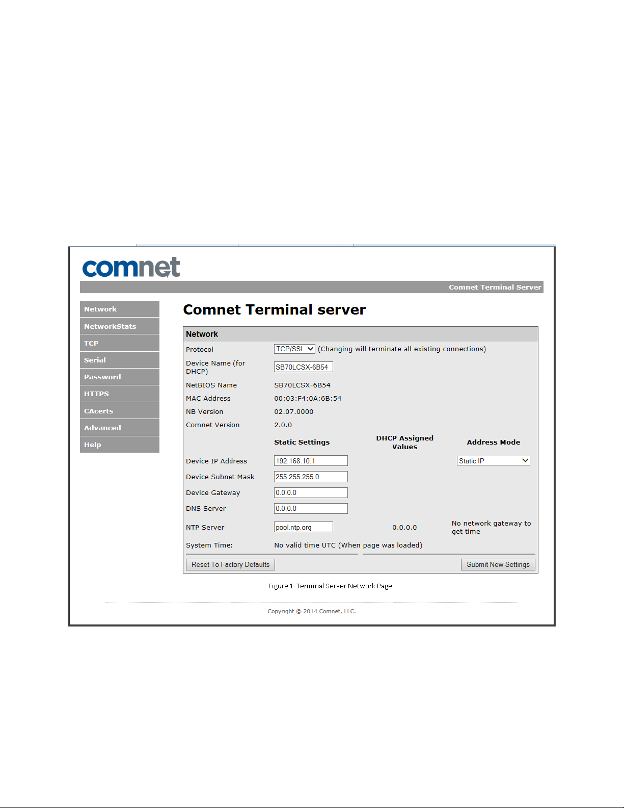
Terminal Server Network Page
Click on the Device IP Address text box.
Change the IP address to an IP address with subnet appropriate for your network. In the following
examples an IP address in subnet 192 .168 .10.x x x will be used.
Configure the IP address to 192.168 .10.10 as shown in the Terminal Server Network Page.
Click Submit New Settings.
TECH SUPPORT: 1.888.678.9427
INS_CNFE3DOE2/M
10/11/11 PAGE 6
Page 7
INSTALLATION AND OPERATION MANUAL CNFE3DOE2/M
Terminal Server Configuration Page
Log in to the terminal server again using the new IP address.
If an IP address in a different subnet was used, be sure to change the PC’s network address to an
IP address in the appropriate subnet.
INS_CNFE3DOE2/M
TECH SUPPORT: 1.888.678.9427
10/11/11 PAGE 7
Page 8
INSTALLATION AND OPERATION MANUAL CNFE3DOE2/M
Using Terminal Server as a Serial Extender over Ethernet
TCP Transport
To use the Terminal Server as a serial extender over Ethernet, connect two terminal servers to your
local Ethernet network.
Configure Server
Configure the first device as a server:
» Set protocol to TCP/SSL on Network page.
Figure 1 Terminal Server Network Page
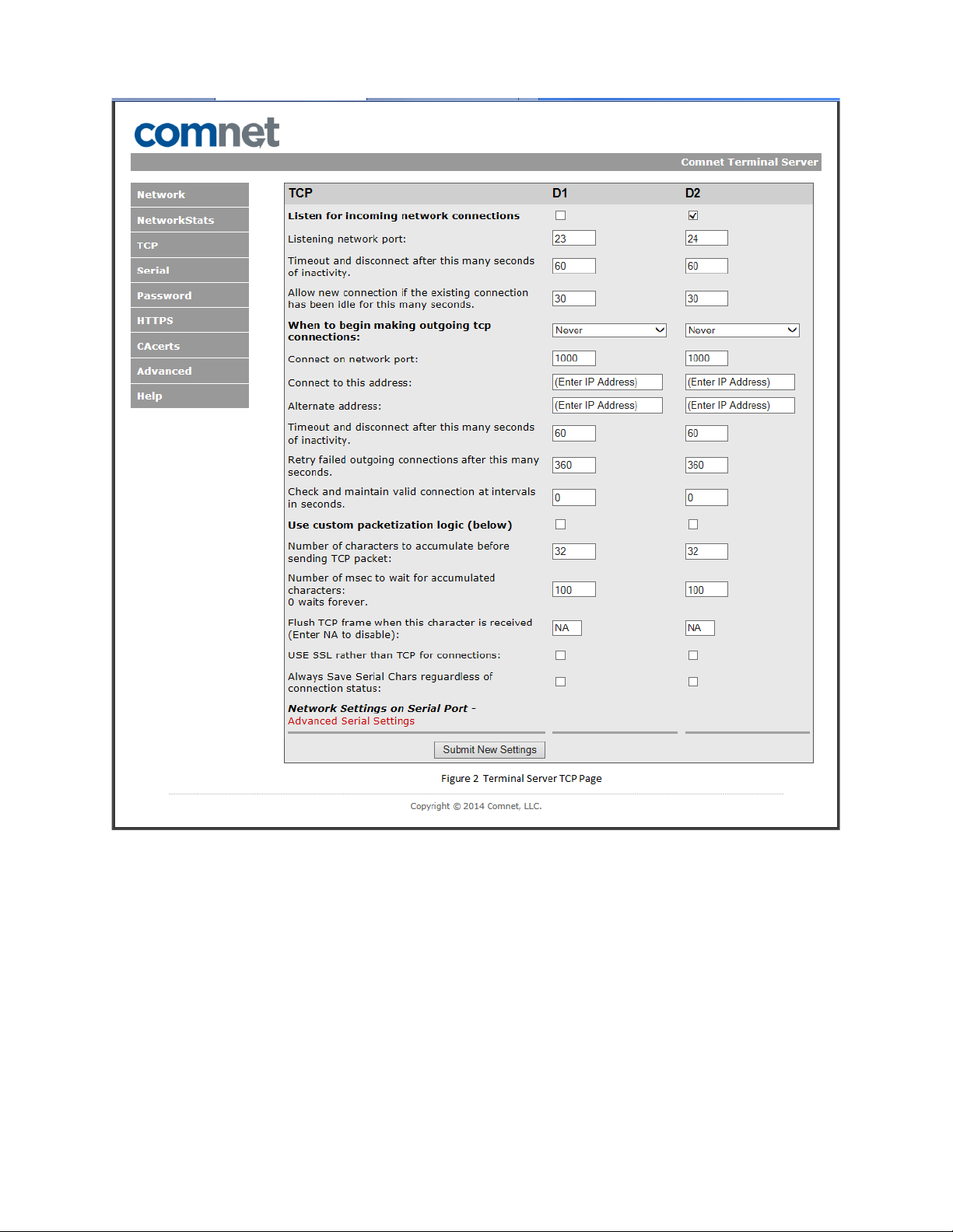
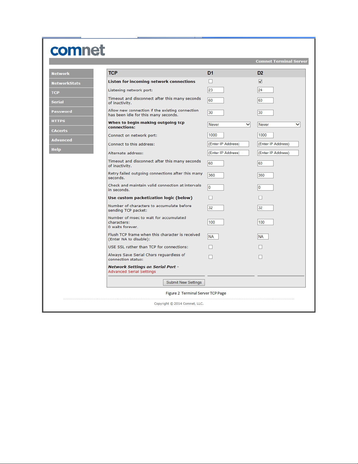
» Click TCP link
» Configure Port1 to listen for incoming connections on port 24
TECH SUPPORT: 1.888.678.9427
INS_CNFE3DOE2/M
10/11/11 PAGE 8
Page 9
INSTALLATION AND OPERATION MANUAL CNFE3DOE2/M
» Click Serial link
» Configure Port1 for RS422
TECH SUPPORT: 1.888.678.9427
Figure 2 Terminal Server TCP Page
INS_CNFE3DOE2/M
10/11/11 PAGE 9
Page 10
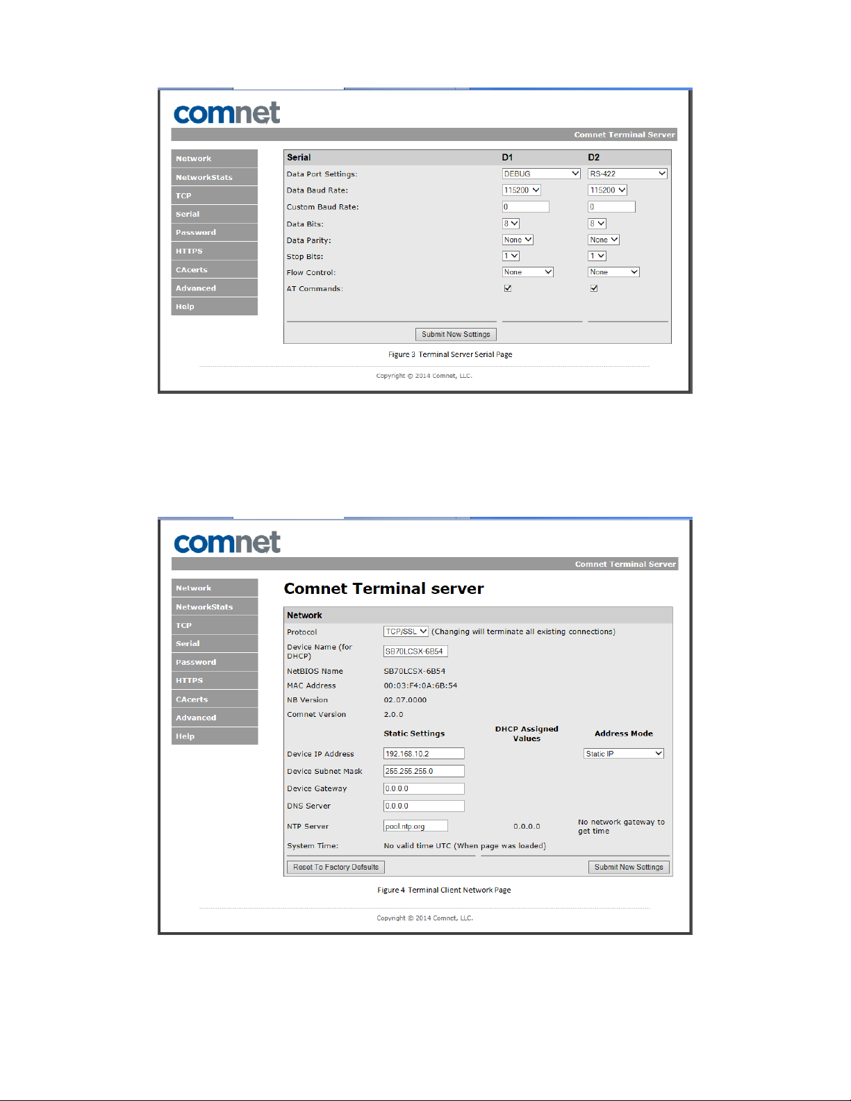
INSTALLATION AND OPERATION MANUAL CNFE3DOE2/M
Figure 3 Terminal Server Serial Page
Configure Client
» Configure the second device as a client.
» Set protocol to TCP/SSL on Network page.
Figure 4 Terminal Client Network Page
» Click TCP link
» Configure Port1 to connect to 192.168.10.1 port 24
TECH SUPPORT: 1.888.678.9427
INS_CNFE3DOE2/M
10/11/11 PAGE 10
Page 11
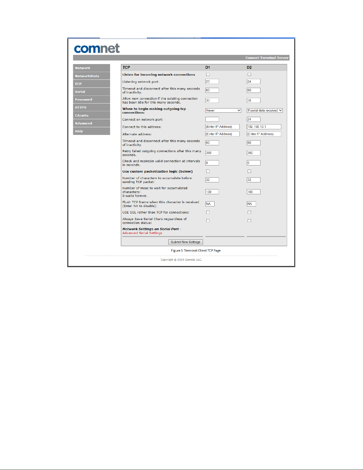
INSTALLATION AND OPERATION MANUAL CNFE3DOE2/M
» Click Serial link
» Configure Port1 for RS422
TECH SUPPORT: 1.888.678.9427
Figure 5 Terminal Client TCP Page
INS_CNFE3DOE2/M
10/11/11 PAGE 11
Page 12
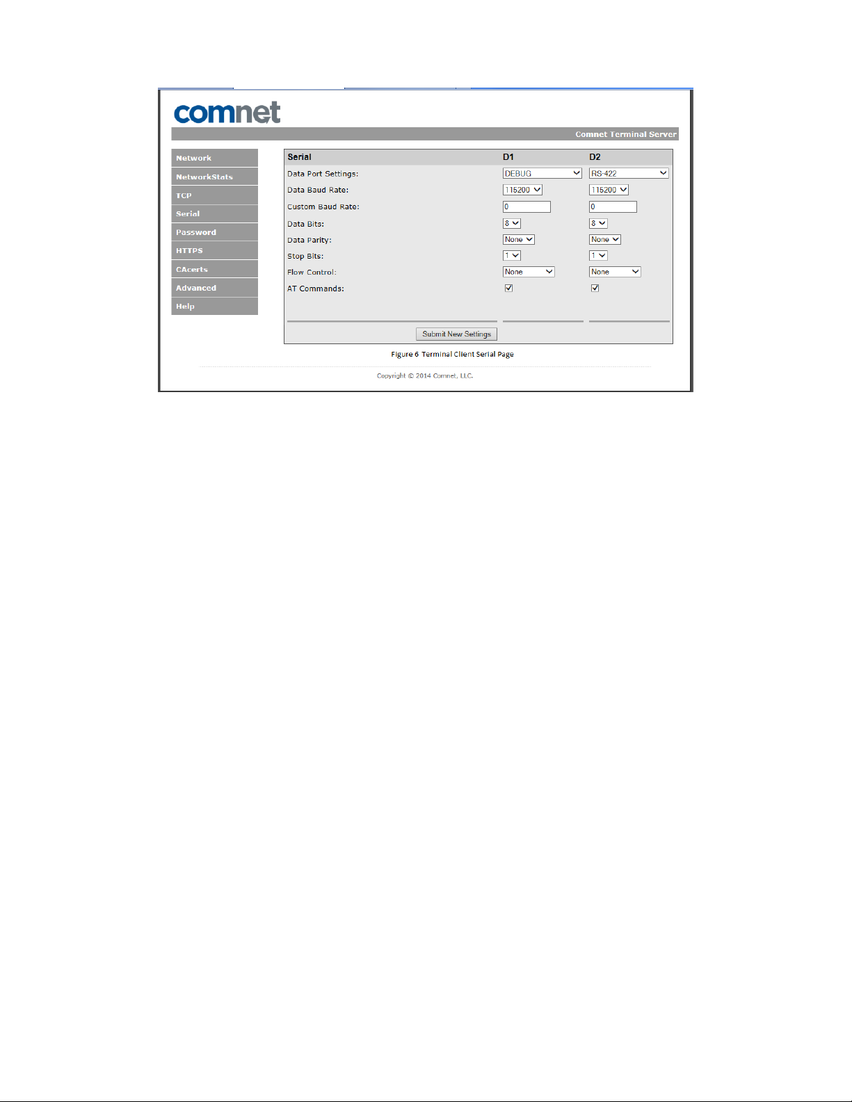
INSTALLATION AND OPERATION MANUAL CNFE3DOE2/M
Figure 6 Terminal Client Serial Page
TECH SUPPORT: 1.888.678.9427
INS_CNFE3DOE2/M
10/11/11 PAGE 12
Page 13

INSTALLATION AND OPERATION MANUAL CNFE3DOE2/M
UDP Transport
To use the Terminal Server as a serial extender over Ethernet utilizing UDP, connect two terminal
servers to your local Ethernet network and configure devices as a client server connection.
Configure Server
» Set protocol to UDP on Network page.
Figure 7 Terminal Server Network Page
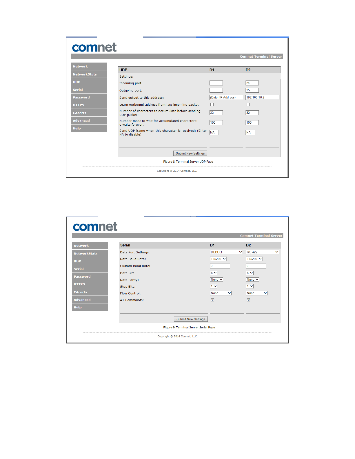
» Click UDP link
» Configure Port1 to receive on port 24 & to transmit to 192.168.10.2 on port 25
TECH SUPPORT: 1.888.678.9427
INS_CNFE3DOE2/M
10/11/11 PAGE 13
Page 14
INSTALLATION AND OPERATION MANUAL CNFE3DOE2/M
» Click Serial link
» Configure Port1 for RS422
Figure 8 Terminal Server UDP Page
Figure 9 Terminal Server Serial Page
TECH SUPPORT: 1.888.678.9427
INS_CNFE3DOE2/M
10/11/11 PAGE 14
Page 15

INSTALLATION AND OPERATION MANUAL CNFE3DOE2/M
Configure Client
» Set protocol to UDP on Network page.
Figure 10 Terminal Client Network Page
» Click UDP link
» Configure Port1 to receive on port 25 & to transmit to 192.168.10.1 on port 24
TECH SUPPORT: 1.888.678.9427
INS_CNFE3DOE2/M
10/11/11 PAGE 15
Page 16

INSTALLATION AND OPERATION MANUAL CNFE3DOE2/M
» Click Serial link
» Configure Port1 for RS422
Figure 11 Terminal Client UDP Page
Figure 12 Terminal Client Serial Page
TECH SUPPORT: 1.888.678.9427
INS_CNFE3DOE2/M
10/11/11 PAGE 16
Page 17

INSTALLATION AND OPERATION MANUAL CNFE3DOE2/M
SSL Transport
To use the Terminal Server as a serial extender over Ethernet utilizing SSL, connect two terminal
servers to your local Ethernet network and configure devices as a client server connection.
Configure Server
» Set protocol to TCP/SSL on Network page.
Figure 13 Terminal Server Network Page
» Click TCP link
» Configure Port1 to listen for incoming connections on port 24
» Check “USE SSL rather than TCP for connection”
TECH SUPPORT: 1.888.678.9427
INS_CNFE3DOE2/M
10/11/11 PAGE 17
Page 18

INSTALLATION AND OPERATION MANUAL CNFE3DOE2/M
» Click Serial link
» Configure Port1 for RS422
TECH SUPPORT: 1.888.678.9427
Figure 14 Terminal Server TCP Page
INS_CNFE3DOE2/M
10/11/11 PAGE 18
Page 19

INSTALLATION AND OPERATION MANUAL CNFE3DOE2/M
Figure 15 Terminal Server Serial Page
» Click HTTPS link
» Select Choose File and load Certificate “device.crt”
» Select Choose File and load Certificate key “device.key”
Figure 16 Terminal Server Certificate and key files
» Select Install Certificate and Key
TECH SUPPORT: 1.888.678.9427
INS_CNFE3DOE2/M
10/11/11 PAGE 19
Page 20

INSTALLATION AND OPERATION MANUAL CNFE3DOE2/M
Configure Client
» Set protocol to TCP/SSL on Network page.
Figure 17 Terminal Client Network Page
» Click TCP link
» Configure Port1 to connect to 192.168.10.1 port 24
» Check “USE SSL rather than TCP for connection”
TECH SUPPORT: 1.888.678.9427
INS_CNFE3DOE2/M
10/11/11 PAGE 20
Page 21

INSTALLATION AND OPERATION MANUAL CNFE3DOE2/M
» Click Serial link
» Configure Port1 for RS422
TECH SUPPORT: 1.888.678.9427
Figure 18 Terminal Client TCP Page
INS_CNFE3DOE2/M
10/11/11 PAGE 21
Page 22

INSTALLATION AND OPERATION MANUAL CNFE3DOE2/M
Figure 19 Terminal Client Serial Page
» Click CAcerts link
» Select Choose File and load Certificate “CA.crt”
Figure 20 Terminal Client Certificate Authority certificate file
» Select Add New client CA
TECH SUPPORT: 1.888.678.9427
INS_CNFE3DOE2/M
10/11/11 PAGE 22
Page 23

INSTALLATION AND OPERATION MANUAL CNFE3DOE2/M
Figure 21 Terminal Client CA Certificate add
TECH SUPPORT: 1.888.678.9427
INS_CNFE3DOE2/M
10/11/11 PAGE 23
Page 24

INSTALLATION AND OPERATION MANUAL CNFE3DOE2/M
Creating openssl certificates
» Open terminal on a Linux machine
Client Certificate
Server Certificate
Figure 22 Client Self Signed Certificate
Figure 23 Server Self Signed Certificate
TECH SUPPORT: 1.888.678.9427
INS_CNFE3DOE2/M
10/11/11 PAGE 24
Page 25

INSTALLATION AND OPERATION MANUAL CNFE3DOE2/M
Figure 24 Client and Server Certificates & keys
TECH SUPPORT: 1.888.678.9427
INS_CNFE3DOE2/M
10/11/11 PAGE 25
Page 26

INSTALLATION AND OPERATION MANUAL CNFE3DOE2/M
SSH Transport
To use the Terminal Server to connect a serial device over Ethernet utilizing SSH, connect a
terminal server and a laptop to your local Ethernet network configuring both devices as a client
server connection.
Configure Server
» Set protocol to SSH on Network page.
Figure 25 Terminal Server Network Page
» Click SSH link
» Configure Port1 to listen for incoming connections on port 22
TECH SUPPORT: 1.888.678.9427
INS_CNFE3DOE2/M
10/11/11 PAGE 26
Page 27

INSTALLATION AND OPERATION MANUAL CNFE3DOE2/M
Figure 26 Terminal Server SSH Page
» Click SSH Keys link
» Click Choose File and select ssh rsa key pair “id_rsa”
» Click Install Key
Figure 27 Terminal Server Keys Page
» Click Serial link
» Configure Port1 for RS422
TECH SUPPORT: 1.888.678.9427
INS_CNFE3DOE2/M
10/11/11 PAGE 27
Page 28

INSTALLATION AND OPERATION MANUAL CNFE3DOE2/M
Figure 28 Terminal Server Serial Page
Configure Client Laptop
» Open Tera Term and select SSH and TCP port 22
Figure 29 Terminal Client Tera Term
» On SSH Authentication Pop Up click RSA and select Private key file id_rsa
TECH SUPPORT: 1.888.678.9427
INS_CNFE3DOE2/M
10/11/11 PAGE 28
Page 29

INSTALLATION AND OPERATION MANUAL CNFE3DOE2/M
TECH SUPPORT: 1.888.678.9427
Figure 30 Terminal Client Tera Term SSH Authentication
INS_CNFE3DOE2/M
10/11/11 PAGE 29
Page 30

INSTALLATION AND OPERATION MANUAL CNFE3DOE2/M
Creating SSH key pairs
Open terminal on a linux machine
Figure 31 Creating SSH key pairs
Telnet Transport
To use the Terminal Server to connect a serial device over Ethernet utilizing Telnet, connect a
terminal server and a laptop to your local Ethernet network configuring both devices as a client
server connection.
Configure Server
» Set protocol to TCP on Network page.
INS_CNFE3DOE2/M
TECH SUPPORT: 1.888.678.9427
10/11/11 PAGE 30
Page 31

INSTALLATION AND OPERATION MANUAL CNFE3DOE2/M
Figure 32 Terminal Server Network Page
» Click TCP link
» Configure Port1 to listen for incoming connections on port 24
TECH SUPPORT: 1.888.678.9427
INS_CNFE3DOE2/M
10/11/11 PAGE 31
Page 32

INSTALLATION AND OPERATION MANUAL CNFE3DOE2/M
» Click Serial link
» Configure Port1 for RS422
TECH SUPPORT: 1.888.678.9427
Figure 33 Terminal Server TCP Page
INS_CNFE3DOE2/M
10/11/11 PAGE 32
Page 33

INSTALLATION AND OPERATION MANUAL CNFE3DOE2/M
Figure 34 Terminal Server Serial Page
Configure Client Laptop
» Open Tera Term and select Telnet and TCP port 24
Figure 35 Terminal Client Tera Term
TECH SUPPORT: 1.888.678.9427
INS_CNFE3DOE2/M
10/11/11 PAGE 33
Page 34

INSTALLATION AND OPERATION MANUAL CNFE3DOE2/M
HTTPS Configuration
» Click HTTPS
» Select Certificate File to Install Choose File “device.crt”
» Select Key File to Install. Choose File “device.key”
» Click Install Certificate and Key
Figure 36 Terminal Server Certificate and Key files
TECH SUPPORT: 1.888.678.9427
INS_CNFE3DOE2/M
10/11/11 PAGE 34
Page 35

INSTALLATION AND OPERATION MANUAL CNFE3DOE2/M
Internet Explorer Configuration
» Click on tools and select Internet options
TECH SUPPORT: 1.888.678.9427
Figure 37 Terminal Client IE Options
INS_CNFE3DOE2/M
10/11/11 PAGE 35
Page 36

INSTALLATION AND OPERATION MANUAL CNFE3DOE2/M
» Click Content tab and click Certificates
Figure 38 Terminal Client IE Certificates
» Click Trusted Root Certifications Authority tab
TECH SUPPORT: 1.888.678.9427
INS_CNFE3DOE2/M
10/11/11 PAGE 36
Page 37

INSTALLATION AND OPERATION MANUAL CNFE3DOE2/M
Figure 39 Terminal Client IE Root CA
» Click Import…
» Use wizard to load CA certificate “CA.crt”
» Place in Trusted Root Certification Authorities
TECH SUPPORT: 1.888.678.9427
INS_CNFE3DOE2/M
10/11/11 PAGE 37
Page 38

INSTALLATION AND OPERATION MANUAL CNFE3DOE2/M
Figure 40 Terminal Client IE Certificate Store
» Finish wizard and close Internet Explorer
» Terminal Server is now accessible using HTTPS with Internet Explorer
TECH SUPPORT: 1.888.678.9427
INS_CNFE3DOE2/M
10/11/11 PAGE 38
Page 39

INSTALLATION AND OPERATION MANUAL CNFE3DOE2/M
FireFox Configuration
» Click on tools and select options
Figure 41 Terminal Client FireFox Options
» Click Privacy & Security
» Click View Certificates
Figure 42 Terminal Client FireFox Certificate MGR
» Click Servers and Add Exception
TECH SUPPORT: 1.888.678.9427
INS_CNFE3DOE2/M
10/11/11 PAGE 39
Page 40

INSTALLATION AND OPERATION MANUAL CNFE3DOE2/M
Figure 43 Terminal Client FireFox Exception
» Click Get Certificate
» Click Confirm Security Exception
» Close FireFox
» Terminal Server is now accessible using HTTPS with FireFox
OpenSSL Certificate, key and CA for HTTPS
» Use same SSL certificates
TECH SUPPORT: 1.888.678.9427
INS_CNFE3DOE2/M
10/11/11 PAGE 40
Page 41

INSTALLATION AND OPERATION MANUAL CNFE3DOE2/M
Console Port Access
One serial port may be designated as a console port using USB to RS232 cable. The console
port may be used to view and change the IP address as well as access other system information.
Debug mode will not forward any serial data but is only used to access the terminal server host.
» Click Serial Link
» Configure Port0 for Debug
Figure 44 Terminal Server Serial Page
TECH SUPPORT: 1.888.678.9427
INS_CNFE3DOE2/M
10/11/11 PAGE 41
Page 42

INSTALLATION AND OPERATION MANUAL CNFE3DOE2/M
Network Statistics
This page displays information on network statistics and TCP states. Each counter can be set by
entering a value in the box and selecting “Submit New Settings”. All the counters can be cleared
by selecting “Clear All Stats”. A page refresh will update the counters and TCP states.
TX & RX frames - total frames
UDP TX & RX frames - UDP protocol frames
TCP TX & RX frames - TCP protocol frames
D1 - Serial data characters on Port D1
D2 - Serial data characters on Port D2
D1 TCP State States
Idle
Listening on Port 23 state
Connected to IP 192.168.10.200 state
D2 TCP State States
Idle
Listening on Port 24 state
Connected to IP 192.168.10.201 state
TECH SUPPORT: 1.888.678.9427
Figure 45 Terminal Server Network Statistics Page
INS_CNFE3DOE2/M
10/11/11 PAGE 42
Page 43

INSTALLATION AND OPERATION MANUAL CNFE3DOE2/M
Factory Defaults
There are two methods to set the terminal server back to factory defaults.
» Select “Reset to Factory Defaults” on the Network page.
» Press the reset button on the device.
Factory defaults are
» IP ad dr es s 192 .168.10.1/24
» No gateway
» D1 TCP port is configured for listening on port 23
» D2 TCP port is configured for listening on port 24
» D1 serial port is configured as a Debug console port 115200 baud 8 bit/no parity/1 stop
» D2 serial port is configured for RS-232 115200 baud 8 bit/no parity/1 stop
TECH SUPPORT: 1.888.678.9427
Figure 46 Terminal Server Factory Defaults Page Factory Defaults
INS_CNFE3DOE2/M
10/11/11 PAGE 43
Page 44

INSTALLATION AND OPERATION MANUAL CNFE3DOE2/M
Upgrading Firmware
There are four files used to upgrade firmware on the terminal server.
IPSetup Discovers terminal server on the local network and configures its IP
Address.
Autoupdate Loads the application using UDP.
ModuleUpdate Batch file that invokes IPSetup & Autoupdate to configure terminal
server with IP address 192.168.10.1 and loads application.
D1381_ AP P. s19 Application In s-record format.
Module Update
» Setup a local area network with laptop and module (terminal server) on the 192.168.10.0/24
subnet.
» Install ModuleUpdate, IPSetup, Autoupdate & d1381_APP.s19 in same directory.
» Run ModuleUpdate batch file from command prompt where files reside.
» Program will prompt “Connect Module to the network Press any to continue . . .”
» Press any key, program will configure module with:
IP ad dr es s: “192.168 .10 .1”
Subnet Mask: “255.255.255.0”
Gateway: “192.168.10.254”
Flash: d1381_ APP.s19
Figure 47 Terminal Server Upgrade Firmware Director
TECH SUPPORT: 1.888.678.9427
INS_CNFE3DOE2/M
10/11/11 PAGE 44
Page 45

INSTALLATION AND OPERATION MANUAL CNFE3DOE2/M
TECH SUPPORT: 1.888.678.9427
INS_CNFE3DOE2/M
10/11/11 PAGE 45
Page 46

MECHANICAL INSTALLATION INSTRUCTIONS
ComNet Customer Service
Customer Care is ComNet Technology’s global service center, where our
professional staff is ready to answer your questions at any time.
Email ComNet Global Service Center: customercare@comnet.net
3 CORPORATE DRIVE | DANBURY, CT 06810 | USA
T: 203.796.5300 | F: 203.796.5303 | TECH SUPPORT: 1.888.678.9427 | INFO@COMNET.NET
8 TURNBERRY PARK ROAD | GILDERSOME | MORLEY | LEEDS, UK LS27 7LE
T: +44 (0)113 307 6400 | F: +44 (0)113 253 7462 | INFO-EUROPE@COMNET.NET
© 2019 Communications Networks Corpor ation. All Right s Reserved. “ComNet” and the “ComNet Logo” are registered trademarks of Communication Networ ks, LLC.
 Loading...