

Page 1

INSTALLATION AND OPERATION MANUAL
CNFE100(X) Series
10/100 MBPS ETHERNET 2 PORT MEDIA CONVERTER
1 CHANNEL: ELECTRICAL
The CNFE100(X) converts 10/100 Mbps Fast Ethernet from an electrical signal
to an optical signal and back to an electrical signal. The electrical connection
uses an RJ45 data connector.
Depending on the specific model in use, the optical connector is either a ST or
SC, 1 or 2 Fibers, multimode (M) or singlemode (S), and the unit operates on
either AC/DC or DC only power.
The CNFE100(X) Series standard size units may be directly plugged into
the ComNet Rack (Part C1) or operated as a standalone module. The
CNFE100(X)-M small size units operate as standalone modules only.
See Figures 1 – 7 for complete installation details.
OPTICAL
INS_CNFE100(X)_REV–
01/04/10
PAGE 1
Page 2
INSTALLATION AND OPERATION MANUAL CNFE100(X) SERIES
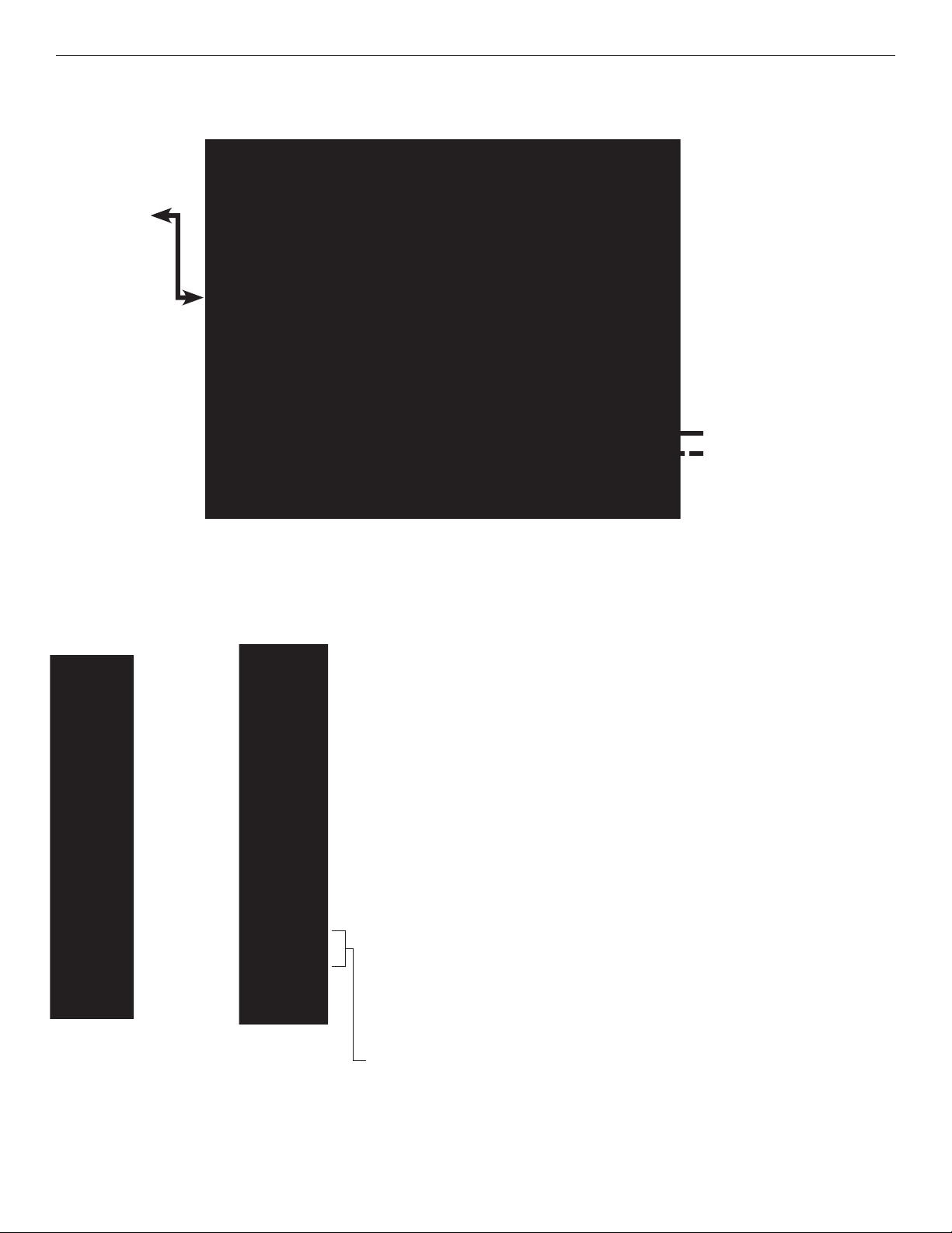
FIGURE 1 – CNFE100(X) SERIES STANDARD SIZE UNIT
MULTIMODE OR
SINGLE MODE
OPTICAL FIBER
BLACK
BLACK WITH WHITE STRIPE
FIGURE 2 – CNFE100(X) SERIES STANDARD SIZE UNIT
REAR PANELFRONT PANEL
NOTE: Remove Electrical Connector for Rack Mount Units
TECH SUPPORT: 1.888.678.9427
INS_CNFE100(X)_REV–
01/04/10
PAGE 2
Page 3

INSTALLATION AND OPERATION MANUAL CNFE100(X) SERIES
FIGURE 4 – CNFE100(X) SERIES SMALL SIZE UNIT
MULTIMODE OR
SINGLE MODE
OPTICAL FIBER
BLACK
BLACK WITH WHITE STRIPE
FIGURE 5 – CNFE100(X) SERIES SMALL SIZE UNIT
REAR PANELFRONT PANEL
TECH SUPPORT: 1.888.678.9427
INS_CNFE100(X)_REV–
01/04/10
PAGE 3
Page 4

FIGURE 6 – POSSIBLE ETHERNET CONFIGURATIONS
Ethernet IEEE 802.3 Network Element determined by user.
SINGLE FIBER
Optical Fiber
ST
Connectors
Ethernet IEEE 802.3
Network Element
TWO FIBER
Ethernet IEEE 802.3
Network Element
CAT5e/6 with
RJ45 Connections
CAT5e/6 with
RJ45 Connections
CNFE1002M1A
CNFE1003M2A
Optical Fibers
SC
Connectors
CNFE1002M1B
CNFE1003M2B
CAT5e/6 with
RJ45 Connections
Ethernet IEEE 802.3
Network Element
CAT5e/6 with
RJ45 Connections
Ethernet IEEE 802.3
Network Element
FIGURE 7 – LED INDICATORS
LINK POWER
GREEN
OFF
Ethernet link has
been established at
the RJ45 connector.
Unit Powered Down
Unit powered up
INS_CNFE100(X)_REV–
01/04/10
PAGE 4
Page 5

MECHANICAL INSTALLATION INSTRUCTIONS
INSTALLATION CONSIDERATIONS
This fiber-optic link is supplied as a Standalone/Rack module. Units
should be installed in dry locations protected from extremes of
temperature and humidity.
STANDALONE MODULE:
The unit is provided with a mounting plate with holes for two No. 6
pan head screws (3 mm or 3.55 mm). Attach the module to a solid
piece of wood using two No. 6 pan head wood screws with a
minimum penetration into the wood of 3/4 inch. (Screws not
supplied). See Figure A.
RACK MODULE:
The unit is designed to be installed in the ComNet 19-inch (483-mm)
EIA standard card-cage rack, the C1-US, C1-EU, or the C1-CH. Follow
these guidelines to install rack cards after performing module setup
procedures.
C1-US, C1-EU, C1-AU OR C1-CH CARD CAGE RACKS
CAUTION: Although the units are hot-swappable and may be installed
without turning power off to the rack, ComNet recommends that
the power supply be turned off and that the rack power supply
is disconnected from any power source. Note: Remove electrical
connector before installing in card cage rack.
FIGURE A
Dimensions are for a standard ComNet™ one slot module
.156 [3.96 mm]
.313 [7.95 mm]
1. Make sure that the card is oriented right side up, and slide it into
the card guides in the rack until the edge connector at the back
of the card seats in the corresponding slot in the rack’s connector
panel. Seating may require thumb pressure on the top and bottom
of the card’s front panel.
CAUTION: Take care not to press on any of the LEDs.
2. Tighten the two thumb screws on the card until the front panel of
the card is seated against the front of the rack.
WARNING: Unit is to be used with a Listed Class 2 or LPS power supply rated 9-12 VDC @ 1A.
WARNING: This unit should be installed in a restricted access location; available through the use of a lock and key or other means of security. Access should
be limited to service personnel who have been instructed about the reasons for the restrictions to the location. Any and all precautions should be taken and
controlled by the authority responsible for the location.
IMPORTANT SAFEGUARDS:
A) Elevated Operating Ambient - If installed in a closed or multi-unit rack assembly, the operating ambient temperature of the rack environment may be
greater than room ambient. Therefore, consideration should be given to installing the equipment in an environment compatible with the maximum ambient
temperature (Tma) specified by the manufacturer.
B) Reduced Air Flow - Installation of the equipment in a rack should be such that the amount of air flow required for safe operation of the equipment is not
compromised.
3 CORPORATE DRIVE | DANBURY, CT 06810 | USA
T: 203.796.5300 | F: 203.796.5303 | TECH SUPPORT: 1.888.678.9427 | INFO@COMNET.NET
8 TURNBERRY PARK ROAD | GILDERSOME | MORLEY | LEEDS, UK LS27 7LE
T: +44 (0)113 307 6400 | F: +44 (0)113 253 7462 | INFO-EUROPE@COMNET.NET
© 2010 Communications Networks Corporation. All Rights Reserved. “ComNet” and the “ComNet Logo” are registered trademarks of Communication Networks, LLC.
INS_CNFE100(X)_REV–
01/04/10
PAGE 5
 Loading...