

Page 1
F™ A
D
P
E
R
ASTCOM
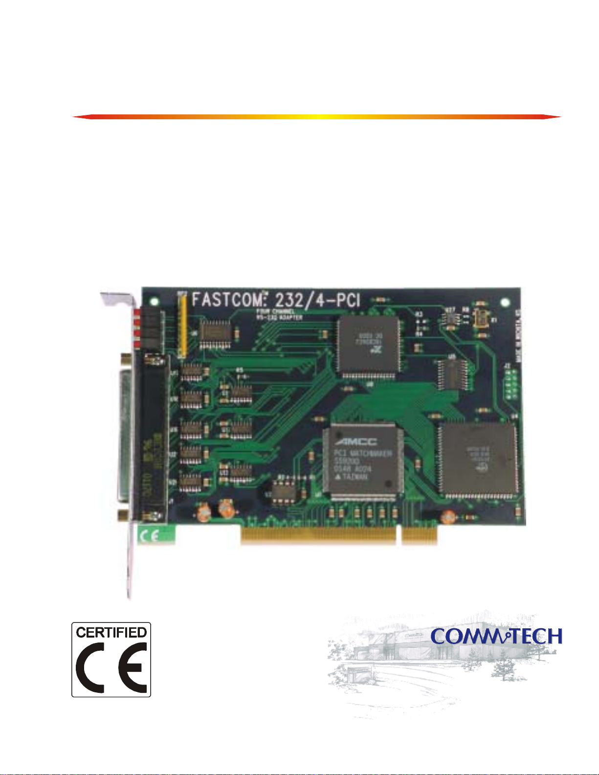
FASTCOM™: 232/4-PCI
Advanced Four Channel RS-232 Interface
Hardware Reference Manual
for PCI Bus
A
T
S
Manufactured by:
9011 E 37th St N
Wichita KS 67226-2006
Page 2

Page 3

9011 E. 37TH STREET N.
WICHITA, KANSAS 67226-2006
(316) 636-1131
FAX (316) 636-1163
http://www.commtech-fastcom.com/
COPYRIGHT (C) 1999, 2002, 2003
All rights reserved, including those to reproduce this document or parts thereof in
any form without permission in writing from Commtech, Inc.
FASTCOM and SMART14 are trademarks of Commtech, Inc.
IBM is a registered trademark of International Business Machines Corporation.
Microsoft is a registered trademark of Microsoft Corporation.
WINDOWS is a trademark of Microsoft Corporation.
Page 4

REVISION NOTES
REVISION PAGE NUMBER CHANGES MADE
2.1 8 Swapped DSR and DCD on loop back plug
2.2 12 Changed warranty to 2 years
2.3 6 Added link to installation manual
2.4 10 Updated contact information
2.5 3,4
2.6 10 Changed warranty period to lifetime
6-8
description
Changed 1.5 Mbaud to 725 Kbaud
Updated Testing Installation and Fastcom
Serial Settings
Page 5

CONTENTS
“CE” CERTIFICATE .............................................................................................................. 1
INTRODUCTION
Description / Block Diagram
Specifications / Features
Board Layout
INSTALLATION
Installing the Hardware
Testing the Installation
FASTCOM SERIAL SETTINGS
ADAPTER CABLE
TECHNICAL SUPPORT
APPENDIX A
16C854 UART Technical Data
................................................................................................................... 5
..................................................................................................... 6
................................................................................................................ 9
..................................................................................................... 10
............................................................................................ 3
................................................................................................. 4
/ Software................................................................................... 6
............................................................................................ 8
...................................................................................... 11
Page 6

Page 7

1
EUROPEAN UNION DECLARATION OF CONFORMITY
Information Technology Equipment
The Company COMMTECH, INC. declares under its own and full responsibility that the product
" Fastcom: 232/4-PCI - Revision 1.0 "
on which is attached this Certificate is compliant to the "89/336/EEC" Directive, amended by 92/31/EEC and
93/88/EEC.
[ ] The product identified above complies with the requirements of the above EU Directive by meeting the
following standards:
• EN 50081-1 (1992) EMC Generic Emission Standard - Part 1, Residential, Commercial and Light Industry
- EN 55022 (1995), CISPR 22 (1993) Limits and Methods of Measurement of Radio Disturbance
Characteristics of Information Technology Equipment, 30 MHz - 1 GHz, Class B Limits
• EN 50082-1 (1992) EMC Generic Immunity Standard - Part 1, Residential, Commercial and Light Industry
- IEC 801-2 (1984), Method of Evaluating Susceptibility to Electrostatic Discharge, Level 4
- IEC 801-3 (1984), Radiated Electromagnetic field Requirements, Level 3
- IEC 801-4 (1988), Electrical Fast Transient/Burst Requirements, Level 2
Products listed on this declaration are exempt from the requirements of the 73/23/EEC directive due to the input
voltage specification as stated in Article 1 of the directive.
The technical documentation required to demonstrate that this product meets the requirements of the EMC Directive
has been compiled by the signatory below and is available for inspection by the relevant enforcement authorities.
In WICHITA, KS on December 31st of 1995
9011 E. 37th Street North
Wichita, KS 67226-2006
(316) 636-1131
Fax (316) 636-1163
Mr. Glen R. Alvis
Chief Engineer
Page 8

2
Page 9
3
INTRODUCTION
The Fastcom: 232/4-PCI adapter is one of the fastest, most advanced four-channel RS-232 adapter in the
industry. Primarily designed for commercial, industrial, and OEM applications, the Fastcom: 232/4-PCI features
four discrete RS-232 channels, complete with all standard hand-shaking signals for each channel.
The advanced universal asynchronous receiver and transmitter (UART) chips used on the Fastcom: 232/4-PCI
are fully register compatible with standard 16C550 UARTs, but provide extraordinary 128 byte FIFOs for
receive and transmit buffering. This buffering is extremely valuable when working with RS-232
communications within high-overhead operating systems such as Windows NT and Windows 98. The fourchannel advanced UARTs on the Fastcom: 232/4-PCI can utilize all standard baud rates plus a high-speed
mode capable of up to an amazing 725 Kbps. (RS-232 data rates are realistically limited by cable length and
driver/receiver characteristics to data rates less than 725 Kbaud.) If your application requires faster data rates or
better noise immunity, we suggest you try our Mega-Baud family of RS232 adapters or our RS-422 family of PCI
adapters, such as the Fastcom: 422/4-PCI.
Software drivers for Windows 98/NT/2000/XP, and Linux are supplied. Multiple Fastcom: 232/4-PCI adapters can
be installed in all operating systems.
The Fastcom RS-232-PCI family also includes the eight-channel Fastcom: 232/8-PCI and the isolated ground
two-channel Fastcom: IG232/2-PCI. ISA bus versions are also available.
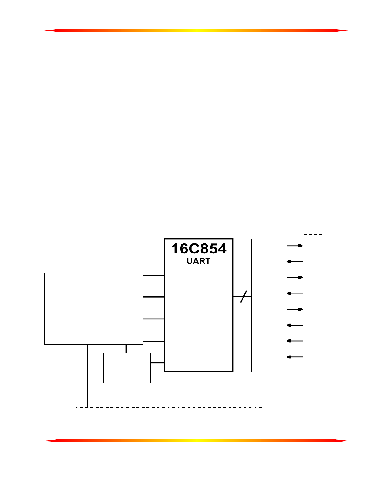
The following is the basic structure of the Fastcom: 232/4-PCI:
CHANNEL 1 (OF 4)
RS-232
DB37
PCI
INTERFACE
CONTROLLER
CLOCK
CONTROL
REGISTER
CS
A0-A2
DATA
INTERRUPT
CLOCK
TXD
RXD
RTS
8
DRIVERS /
RECEIVERS
CTS
DTR
DSR
DCD
RI
PCI BUS
Page 10

4
SPECIFICATIONS:
UART 16C854
BUFFERING Transmit - 128 bytes
Receive - 128 bytes
INTERFACE RS-232C
TXD, RXD, DTR, DSR, DCD, RTS, CTS, RI
BUS PCI
POWER
REQUIREMENTS: +5 600mA (Typical)
+12 100mA
- 12 100mA
ADDRESS
REQUIREMENTS: PCI Controller 128 bytes
UARTs 32 bytes
Control Registers 4 bytes
INTERRUPT
REQUIREMENTS: 1 (per board)
FEATURES:
High performance 16C854 UARTS
Standard
All baud rates up to 725 Kbaud*
128 byte FIFOs for improved throughput
User programmable baud rate
“Switchless” design
Durable Cables with RFI shielding
Comprehensive Hardware and Software Documentation
Made in Wichita, Kansas, USA
on the Fastcom: 232/4-PCI, no extra charge
* RS-232 data rates are realistically limited by cable length and driver/receiver characteristics to less than 725
Kbps. A clock change is required to achieve baud rates higher than 115.2 Kbps.
Page 11
FASTCOM: 232/4-PCI
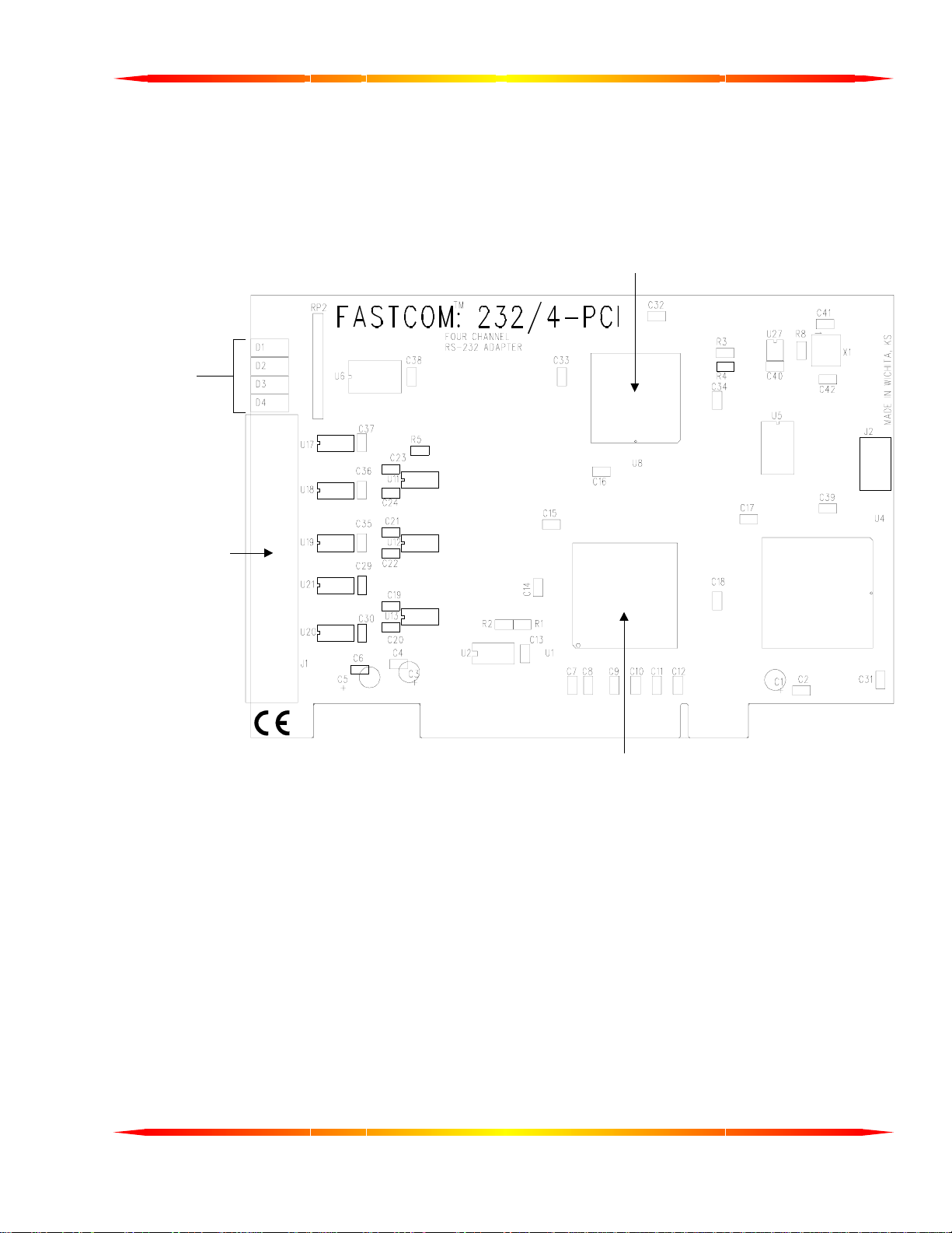
BOARD LAYOUT
TRANSMIT /
RECEIVE
LEDs
5
16C854
UART
DB37
CONNECTOR
PCI
CONTROLLER
PACKING LIST
FASTCOM: 232/4-PCI CARD
CABLE ASSEMBLY
FASTCOM CD
If an omission has been made, please call technical support for a replacement.
Page 12
6
HARDWARE INSTALLATION
Important: Observe Electrostatic Discharge (ESD) precautions when handling the Fastcom: 232/4-PCI
board.
1. Unpack the Fastcom: 232/4-PCI. Keep the box and static bag for warranty repair returns
2. Select an open PCI slot in your PC.
3. After removing the blank bracket from your PC, install the Fastcom: 232/4-PCI in the PC by pressing it firmly
into the slot. Install the bracket screw to hold it firmly in place.
4. Re-install the cover on your PC.
.
SOFTWARE INSTALLATION
Select the link above to open the Installation Manual. Under Fastcom – Async-PCI series cards, select your
operating system and follow the instructions. When you are finished, select Fastcom: 232/4-PCI from the list at
the end of the Fastcom – Async-PCI series cards section to return to this manual.
TESTING THE INSTALLATION
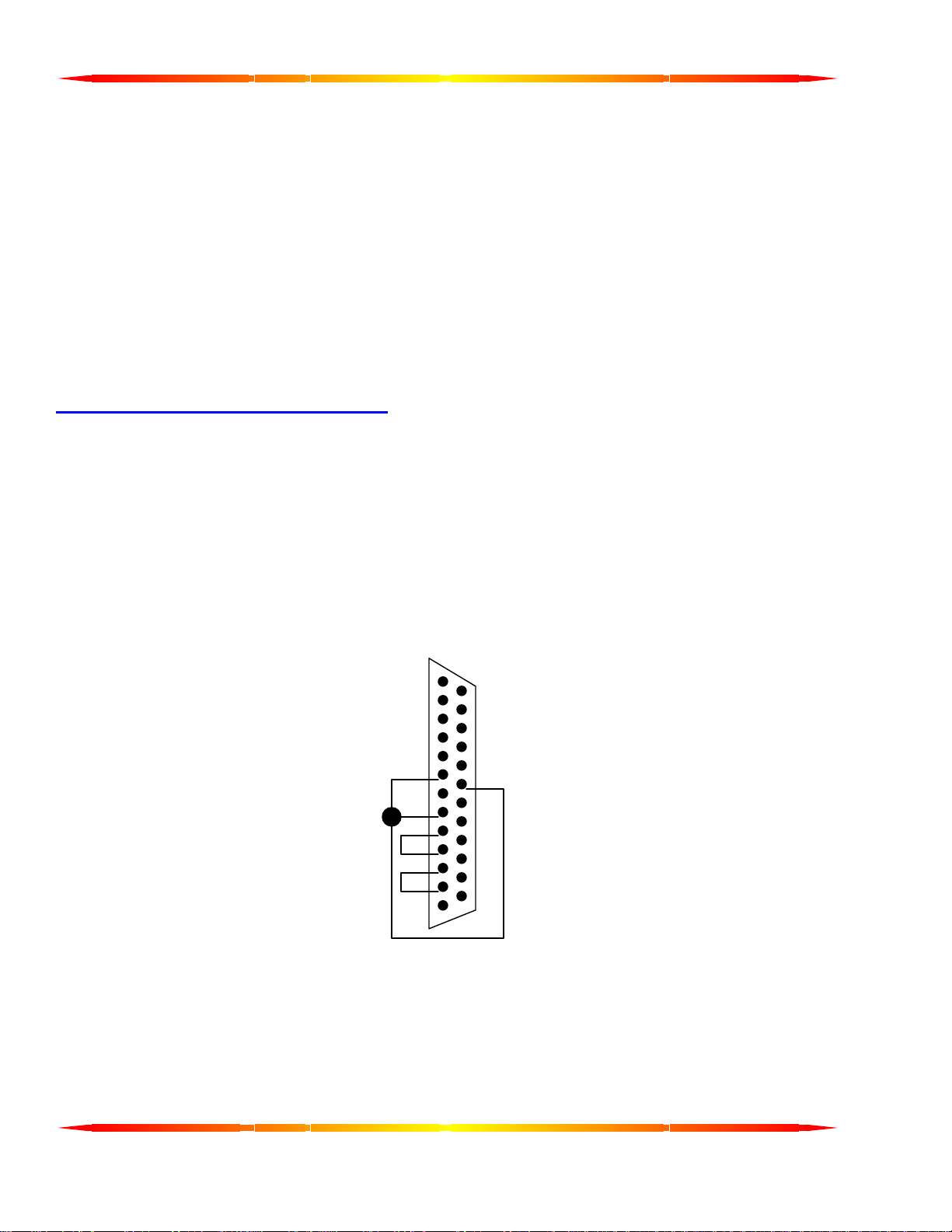
To fully test the installation of your Fastcom: 232/4-PCI, you will need to build a "loop back plug". Materials
needed are a DB25 female receptacle, solder cup style, and a few short pieces of 20 or 24 AWG stranded wire.
This loop back plug can be used to test any RS-232 port. Jumper the pins together on the DB25 as illustrated
below:
2 TRANSMIT
3 RECEIVE
4 RTS
5 CTS
6 DSR
8 DCD
20 DTR
TESTING YOUR FASTCOM ASYNC PCI PORT IN WINDOWS
These instructions assume that you have already installed the card and have followed the installation instructions.
The SERIALGT.EXE program (98, NT), or the Device Manager (2K, XP), should show the boards/ports that are
installed, and the COM numbers assigned to those ports.
1. Attach the “octopus” cable supplied to the DB37 connector. Install the loopback plug on the port to test.
8
6
5
4
3
2
20
Page 13

7
2. Find and run the TTY example program (simple terminal).
From the Start menu, choose Run, browse to and select D:\Fastcom_disks\AsyncPCI\tty\tty2.exe.
Click the Open button.
Click the OK button to run the program.
3. With the TTY program running, select Settings from the menu.
Select the COM port number that has the loopback plug on it.
Uncheck all of the flow control checkboxes (DTR/DSR, RTS/CTS, XON/XOFF).
Click OK.
From the TTY Main menu select Action, then Connect.
4. At this point you should get a blinking cursor in the upper left corner (under the menu bar).
5. You should be able to type on the keyboard and see the letters that you type on the screen. If you see what
you are typing, then your port is installed and operating properly.
If you do not get to the blinking cursor stage, but rather encounter a “Connection Failed” message box, some
possible causes are:
1. In NT, if multiple ports are opened (running more than one instance of TTY), the ports are using the same
IRQ, and the PermitShare registry entry is 0, the second port to be opened will fail. Use the registry
editor and expand HKEY_LOCAL_MACHINE ->SYSTEM ->CurrentControlSet ->Services ->Serial,
change the PermitShare value from 0 to 1, reboot, and run the test again.
2. The interrupt that was selected by the plug-and-play bios is trying to be shared with another device that is
not configured to share the IRQ (either Device or Driver Exclusive IRQ setting). Try a different PCI slot or
disable the other offending device.
3. IRQ steering is enabled on Windows 98 and Windows is not assigning an IRQ to the Fastcom card. Try
disabling IRQ steering or varying the options in Control Panel ->System ->Device Manager ->System
Devices ->PCI Bus.
4. Multiple COMx assignments. In Windows NT, the driver setup assumes that there are not any ports
installed above COM4, and starts assigning the Fastcom ports at COM5. If there is already a COM5 (or
higher) in the system, it is likely that the Fastcom ports are being assigned to the same port name(s).
Run the SERIALGT.EXE program (D:\Fastcom_disks\AsyncPCI\nt\serialgt.exe for Windows NT,
D:\Fastcom_disks\AsyncPCI\95\serialgt.exe for Windows95) and re-assign the com port numbers to these
ports to be different than any other ports in the system.
If you get to the blinking cursor stage, but do not see what you type with the loopback installed, some possible
reasons are:
1. Incorrect/faulty loopback construction or a bad connection.
2. The port is setup to have RS-485 enabled and the “RX Echo Disable” checkbox is checked. If the RX
Echo Disable is checked you will be unable to run a simple loopback test, as the purpose of the echo
disable is to strip the characters that are sent/received at the same time. Uncheck the RX Echo disable,
reboot, and try the test again.
3. The RTS/CTS flow control is checked and there is not a RTS->CTS loopback or the CTS disabled
checkbox was unchecked. If you enable flow control, you must allow CTS to be active in order for the
driver to transmit data. Either disable flow control or wire the RTS->CTS (and possibly DTR->DSR) loops
and try the test again.
4. The loopback plug is not on the correct port/cable.
Page 14

8
FASTCOM SERIAL SETTINGS
These settings can be accessed using the application serialgt.exe (Windows 98/NT) or in the Fastcom Serial Settings tab of
the Fastcom AsyncPCI Communications Port Properties dialog (Windows 2K/XP), which is found in the device manager under
Ports (COM & LPT).
CLOCK/4
Clock divisors of 1 and 4 are available. Clearing the checkbox selects a divisor of 1 and setting the checkbox
selects a divisor of 4. It is best to leave this box unchecked.
RX Trigger
Determines the number of bytes that will be stored in the receive FIFO on the 16C854 before an interrupt is
triggered. Valid values are from 1 to 128 bytes. The optimal setting is 64 bytes. For 16C550 compatibility,
set to 8.
TX Trigger
Determines the number of bytes remaining in the transmit FIFO on the 16C854 before an interrupt is
triggered. Valid values are from 0 to 127 bytes. The optimal setting is 64 bytes. For 16C550 compatibility,
set to 0.
TX Write Size
Determines the number of bytes sent to the board at a time. Valid values are from 1 to 128. This number
plus the TX Trigger value should not exceed 128. The optimal value is 64. For 16C550 compatibility, set to
16 or 1.
BaudTable (Win2K/XP)
This table represents the standard baud rates that the Fastcom card will currently support. If you wish to use
a non-standard baud, you may enter it into one of the boxes on the table and hit the tab key (do not hit enter,
hitting enter will exit the program). This will set the on-board clock generator to a frequency (see Input
Frequency below) that will divide down to the new baud rate. The rest of the table will also be updated to
reflect other bauds that can be used with the calculated clock frequency. If you wish to return to the standard
rates, you can set the top box to 115200 and hit tab; the rest of the bauds will be filled in.
Note: The baud rates that you set will not be available to standard Windows applications like HyperTerminal.
The new rates will be available to you in your code or in applications that allow user defined baud rates such
as TTY2, which can be found on the Fastcom disk (Fastcom_CD\Fastcom_disks\AsyncPCI\tty\tty2.exe).
THIS SETTING=THIS BITRATE (Baud Rate Substitution Table) (Win98/NT)
Under THIS SETTING you will see the standard PC baud rates, from 115.2K to 300. If you wish to use a
baud rate not shown, type the baud rate in the box next to 115200 (e.g., type 128K as 128000), and hit the
tab key. Do not hit enter. Hitting enter will exit the program. If the baud rate changes after you tab, move to
the next box down and try again. Continue moving down until the baud rate stays the way you want it. Now
note the standard PC baud rate to the left of the box you ended on. You will select this standard baud rate to
set up your com ports, and the baud rate you require will be substituted. If you receive an error message
stating that the maximum baud rate was exceeded, change the Clock Divisor to 1 and try again.
INPUT FREQUENCY
This is the calculated frequency required to generate the baud rate requested. When you click OK on the
Fastcom Serial Settings page, this frequency is sent to the clock generator and the new baud rates will be
available.
OTHERS
Auto 485, CTS Disable, 485 Enable, RX Echo Disable, Enable Source, and Sample Rate do not apply to this
board. Do not change these options as they will have no positive affect on settings for this board and may
cause instability.
Page 15

9
FASTCOM: 232/4-PCI ADAPTER CABLE
We provide access to the four channels on the FASTCOM: 232/4-PCI adapter through a shielded DB37
connector and an adapter cable (supplied with the board). The adapter cable consists of a DB37 male plug
fanning out to four standard DB25 male plugs.
DB37 PIN DESCRIPTION
N.C.
DCD3
GND
CTS3
RXD3
RI4
DTR4
DSR4
RTS4
TXD4
DCD2
GND
CTS2
RXD2
RI1
DTR1
DSR1
RTS1
TXD1
- 1
-
-
-
-
-
-
-
-
-
-
-
-
-
-
-
-
-
-
2
3
4
5
6
7
8
9
10
11
12
13
14
15
16
17
18
19
20 21
22
23
24
25
26
27
28
29
30
31
32
33
34
35
36
37
-
-
-
-
-
-
-
-
-
-
-
-
-
-
-
-
-
RI3
DTR3
DSR3
RTS3
TXD3
DCD4
GND
CTS4
RXD4
RI2
DTR2
DSR2
RTS2
TXD2
DCD1
GND
CTS1
RXD1
DB25 PIN DESCRIPTION
(Four Plugs)
DCD
GND
DSR
CTS
RTS
RXD
TXD
- 13
- 1
- 11
- 10
- 9
- 8
7
-
- 6
- 5
- 4
- 3
-
2
-
1
25 24 23 22 21 20 -
RI
DTR
2
19 18 17 16 15 14 -
Page 16

10
TECHNICAL SUPPORT
All products manufactured by Commtech are warranted against defective materials and workmanship for the
lifetime of the product. This warranty is available only to the original purchaser. Any product found to be
defective will, at the option of Commtech, be repaired or replaced with no charge for labor or parts not excluded
by the warranty. This warranty does not apply to any products that have been subjected to misuse, abuse, or
accident or as a result of service or modification by anyone other than Commtech. In no case shall Commtech
liability exceed the original product purchase price.
If any Commtech product is damaged such that it cannot be repaired, you can return it to Commtech for
replacement under our Non-Repairable Replacement policy, regardless of the cause of damage. Commtech will
replace the unit at 60% of the then-current list price.
Commtech provides extensive technical support and application suggestions. Most of the problems that occur
with the FASTCOM: 232/4-PCI can be corrected by double-checking the switch positions, your cables and your
program. We recommend that you build the loop back plug that is described in the Programming section of this
manual. With that plug, you can quickly isolate the problem to the board, cables, or software.
If you still have unresolved questions, use the following procedure to get technical support:
1. Call our Technical Support Staff at (316) 636-1131. They are on duty from 9:00 AM to 5:00 PM Central
Time.
If you purchased your board from Kontron America, please call their 7-24 technical support line at 1-800-
480-0044.
2. Ask for technical support for the FASTCOM: 232/4-PCI. Be ready to describe the problem, your computer
system, your application, and your software.
3. If necessary, our staff will give you an RMA number (Return Material Authorization). Use this number on
the mailing label and in all references to your board. Put the board back in its static bag and in its box.
Ship the board back to us as directed.
4. If you prefer, you may FAX a description of the problem to us at (316) 636-1163, or we can be reached on
the Internet at “http://www.commtech-fastcom.com
Kontron America can be reached by telephone at (800) 480-0044 or on the web at
“http://www.kontron.com/support/index.cfm
”.
” or by email at "[email protected]".
Page 17

11
APPENDIX A
16C854
UART DATA
 Loading...