

Page 1

Indoor Wireless AP4600
Quick Installation Guide
Com m Sky
WLAN AP Quick Installation Guide
Com m Sk y
Technologie s
Page 2

Com m Sky
WLAN AP Quick Installation Guide
Copyright Notice
Copyright ©2016 CommSky Technologies, Corp.
This document contains proprietary information which is protected by copyright. All rights are
reserved. No part of this document may be photocopied, reproduced, or translated to another
language without prior written consent of the CommSky Technologies, Corp. CommSky
Technologies is a trademark of CommSky Technologies, Corp., its subsidiaries, and affiliates. All
other trademarks are the property of their respective owners.
In the interest of improving product design, operational function, and reliability, CommSky
Technologies, Corp. reserves the right to change information contained in this manual without prior
notice. All statements, information, and recommendations in this document shall not be construed as
any form of guarantees by CommSky Technologies, Corp.
CommSky Technologies, Corp.
Page 3
Button names are enclosed in angular brackets “< >”; for example: “click
<OK>”。
Com m Sky
WLAN AP Quick Installation Guide
Preface
This guide is aimed to assist with hardware configuration, preparation for installation, installation
using several methods, and system configuration of the CommSky AP 4600 Series Indoor intelligent
Access Points.
The Preface includes the following contents:
Applicable models:
CommSky AP 4600 series of products made by CommSky Technologies, Corp.
Intended audience:
This guide is intended for the following audience:
• Network planners
• Field technical support and maintenance personnel
• Network administrators
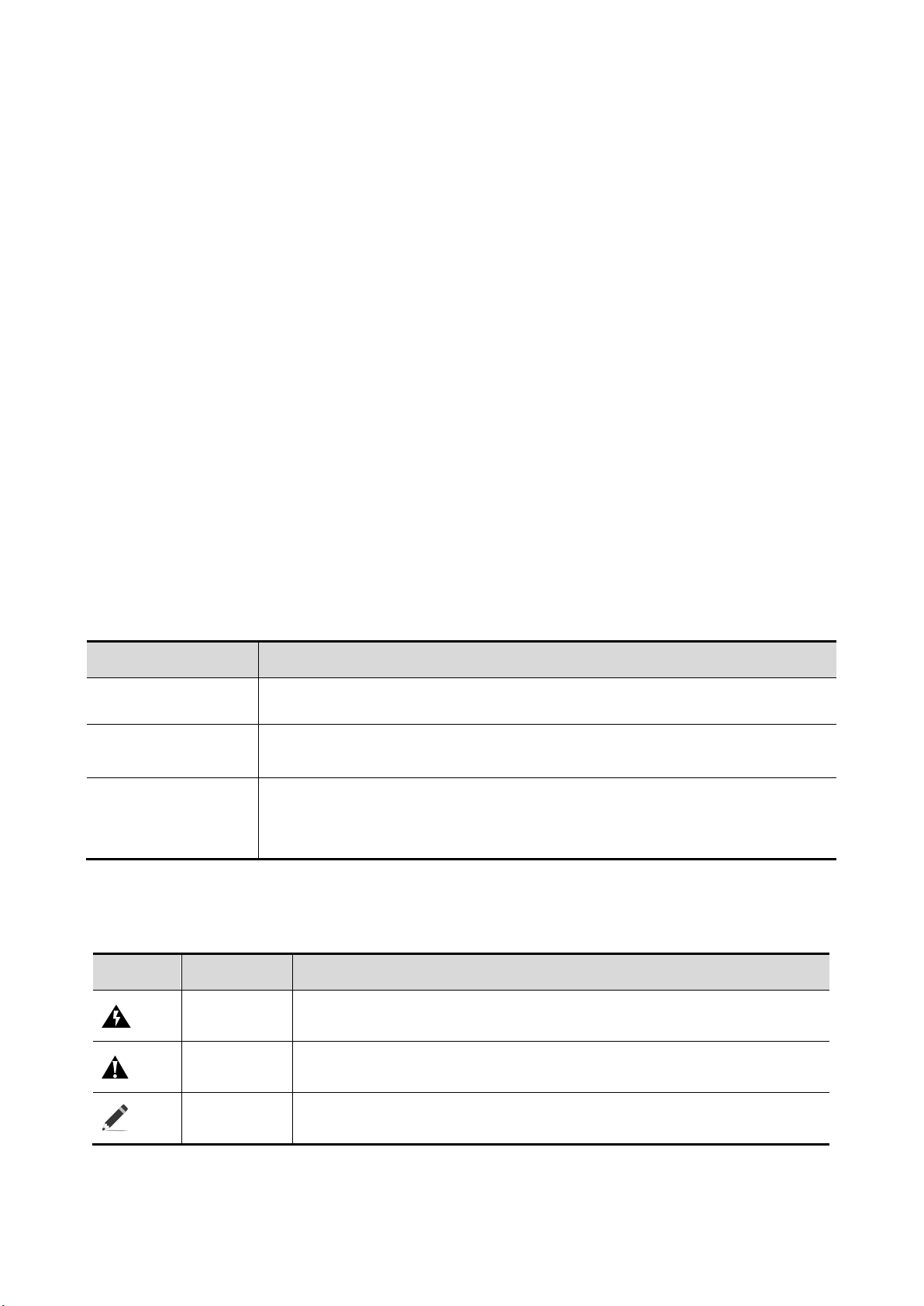
Conventions
1. GUI Conventions
Highlights Meaning
< >
【 】
/
2. Sign Conventions
This manual employs a variety of signs as user tips and warnings.
Icons Levels Description
Window name, menu title, and data table are enclosed in square brackets:
“【 】”,for example: “【New User】popup”。
Multi-level menus are separated by “/”; for example: 【File/New/Folder】
multi-level menu denotes【File】menu’s【New】sub-menu’s【Folder】
selection。
CommSky Technologies, Corp.
Danger
Warning
Note
This is a safety warning. Operation shall be strictly followed as
described. Improper operation may result in personal injury.
This is a safety warning. Improper operation may result in equipment
damage and/or loss of data.
Highlights supplemental information useful to perform operations;
omission of which will not impaired operations.
Page 4

Com m Sky
Obtaining Further Information
Latest documentation can be downloaded from CommSky website (http://www.commsky.com).
CommSky website and product related topics are as follows:
【Product Series】:to obtain product datasheets
【Technology Differentiation】:to obtain information regarding our product/technology
differentiation
【Solution】:to obtain solution materials using our products
【Service and Support / Document Center】:to obtain configuration and maintenance
information for our products
Technical Support
WLAN AP Quick Installation Guide
Email:[email protected]
Phone:400-826-8847
Company Website:www.commsky.com
Feedback
CommSky, Corp. appreciates any feedback on problems and/or corrections with our
documentation. You can contact us using the following methods:
E-mail:[email protected]
Technical support:400-826-8847
CommSky Technologies, Corp.
Page 5

Com m Sky
WLAN AP Quick Installation Guide
Contents
1 LEDs and Ports ................................................................................................................................ 1
1.1 LEDs ........................................................................................................................................... 1
1.2 Ports ............................................................................................................................................ 2
2 Installation Preparation .................................................................................................................. 3
2.1 Safety recommendations ............................................................................................................. 3
2.2 Temperature and humidity .......................................................................................................... 3
2.3 Accessories provided with the AP .............................................................................................. 3
2.4 User-supplied installation tools and equipment .......................................................................... 4
3 AP Installation .................................................................................................................................. 5
3.1 Installation pre-requisites ............................................................................................................ 5
3.2 Check before installation ............................................................................................................ 5
3.3 Determining location for installation .......................................................................................... 5
3.4 Installing the AP ......................................................................................................................... 5
3.5 Connecting the power supply ...................................................................................................... 9
4 Configuration Guide ...................................................................................................................... 11
4.1 Required tools ........................................................................................................................... 11
4.2 Device default configuration ..................................................................................................... 11
4.3 Configuration procedure ........................................................................................................... 11
4.4 Login page ................................................................................................................................ 13
Appendices .......................................................................................................................................... 14
A1 Factory Default Settings ............................................................................................................ 14
A2 List of Toxic and Hazardous Substances .................................................................................. 15
A3 Warranty Card ........................................................................................................................... 17
A4 Qualification Card ..................................................................................................................... 19
CommSky Technologies, Corp.
Page 6
Images in this manual are for reference only. Actual shipped units may have different exterior.
Alternating
blue
Com m Sky
Note
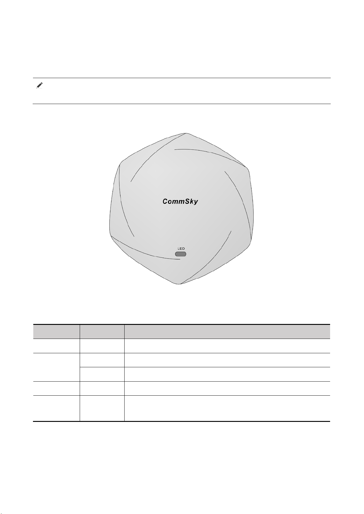
1.1 LEDs
WLAN AP Quick Installation Guide
1 LEDs and Ports
Figure 1 AP 4600 LEDs
Table 1 LED description
Color Status Description
Green Blinking A client is connected to the 2.4G port.
Steady on The AP has been booted, and is in standby state.
Blue
Blinking A client is connected to the 5G port.
Red Steady on The AP is booting.
green and
Blinking Clients are connected to both the 2.4G and 5G radio interfaces.
1 CommSky Technologies, Corp.
Page 7
The LAN 1 port can serve as an uplink interface to access the Internet
or MAN, and as an 802.3at-compliant PoE port at the same time.
Com m Sky
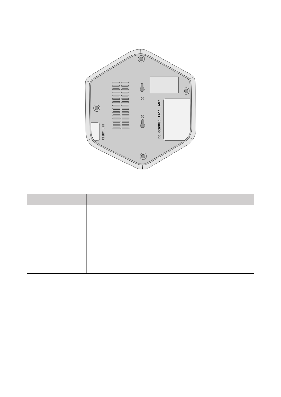
1.2 Ports
WLAN AP Quick Installation Guide
Figure 2 AP 4600 ports
Table 2 Port description
Port Description
RESET Reset button
USB USB port
DC The local power port is used for +48 VDC power supply to the device.
CONSOLE The console port is used for configuration and management.
LAN 1(PoE)
LAN 2 The LAN 2 port can serve as an downlink interface
CommSky Technologies, Corp. 2
Page 8
If condensation occurs on AP as it moved from a cold environment to a warm environment,
Com m Sky
WLAN AP Quick Installation Guide
2 Installation Preparation
2.1 Safety recommendations
Take adequate safety measures to avoid bodily injury and access point damage.
Make sure that the ground is dry and flat and anti-slip measures are in place.
Keep the chassis clean and dust-free.
Do not place the access point in a moist area and avoid liquid surrounding the access point.
Keep the chassis and installation tools away from walkways.
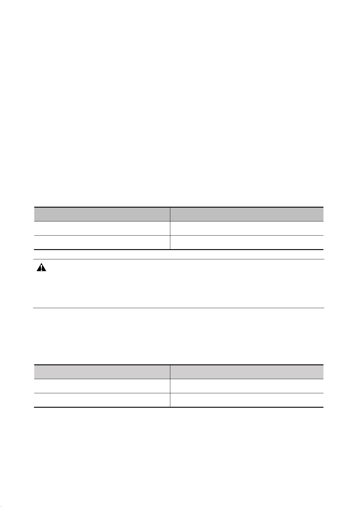
2.2 Temperature and humidity
2.2.1 Temperature requirements
Proper indoor temperature is necessary to ensure correct AP operations. See Table 2-1 for
required operating temperatures.
Table 1 Temperature requirements
Item Required Range
Operating temperature
Storage temperature
Warning
ensure AP is free of condensation prior to power on. This is to prevent any short circuit that may
occur within the device.
2.2.2 Humidity requirements
Proper indoor humidity is necessary to ensure correct AP operations. See Table 2-2 for required
operating humidity.
Table 2 Humidity requirements
Item Required Range
Operating relative humidity 10% to 9 5 %
0℃ to 40℃(long-term)
-40℃ to +70℃
Storage relative humidity 5% to 95%
2.3 Accessories provided with the AP
The following accessories are provided with the AP:
3 CommSky Technologies, Corp.
Page 9
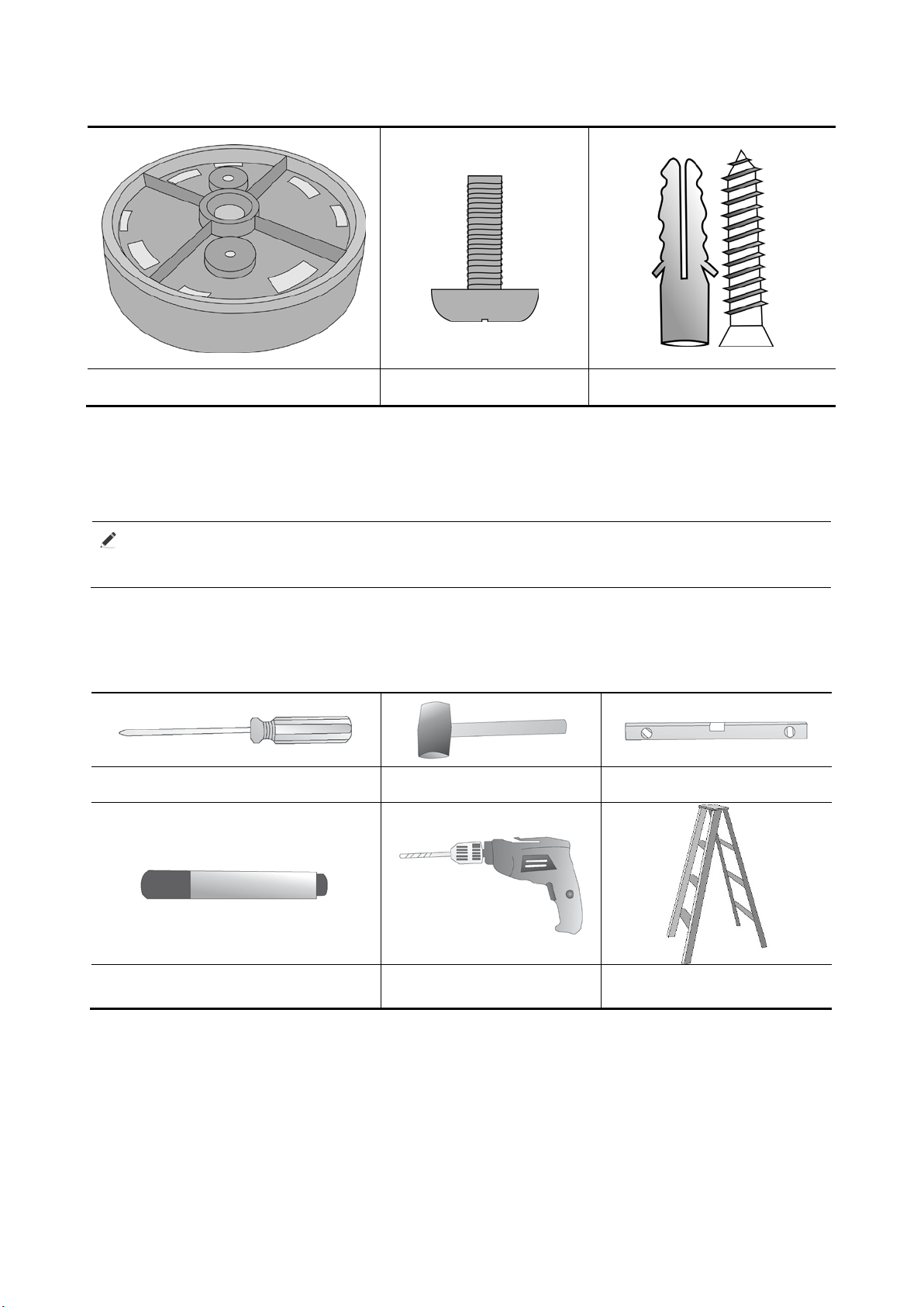
Power adapter, and power cable are user-supplied.
Percussion drill with
matching drills
Com m Sky
Circular support x 1 Unit Pan head screw Wall anchor kit
A packing list will be included with AP delivery. Please confirm all accessories on the packing
list are present. If any part is damaged or missing, please contact your local dealer or technical
support for replacement.
WLAN AP Quick Installation Guide
NOTE
2.4 User-supplied installation tools and equipment
When you install a 4600 access point, you may need the following tools:
Phillips screwdriver Rubber hammer Level
Marker
CommSky Technologies, Corp. 4
Ladder
Page 10

Com m Sky
WLAN AP Quick Installation Guide
3 AP Installation
3.1 Installation pre-requisites
You have read Section 2, Installation Preparation.
All requirements in Section 2, Installation Preparation, are satisfied.
3.2 Check before installation
Prior to installing the AP, please check the following:
Connect power cord to the AP and the network. Check the status LED to make sure the AP is
operating properly. For more information about AP LEDs, see Section 1, LEDs and ports.
Ensure all necessary cabling have been installed.
AP4600 supports 802.at-compliant PoE. For best performance, Commsky recommends to only
use GE connection to supply power to the device.
Record the MAC address and serial number of the AP for future use. MAC address and serial
number can be found on the bottom of the AP.
3.3 Determining location for installation
Determine positions to perform the installation:
Leave as few obstacles (such as wall) as possible between APs and clients.
Install APs away from electronic devices (such as microwave ovens) that may generate radio
frequency (RF) noise.
Install APs in place where they do not hinder daily work and life.
Do not install AP in places where water is seeping, soaking, or condensing. Prevent water and
moisture from entering the AP.
3.4 Installing the AP
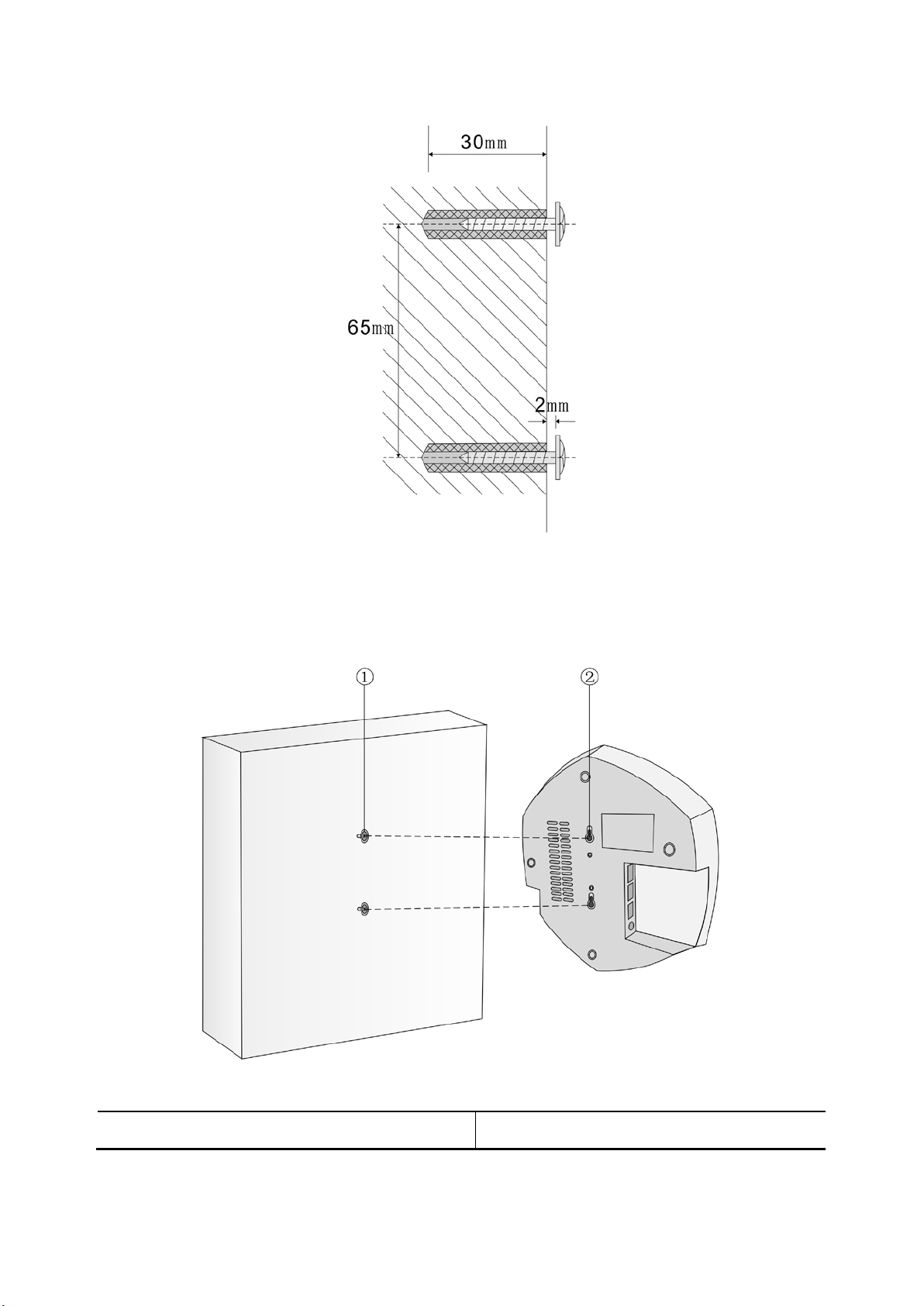
3.4.1 Wall-mounted
Step 1
Mark drilling locations on the wall, with a vertical separation of 65 mm to each other;
Drill two 6.5 mm holes to a depth of approximately 30 mm;
Insert two wall anchors and knock them down into the holes;
Insert two screws, leaving a gap of approximately 2 mm between the wall and the base of the
screw head.
5 CommSky Technologies, Corp.
Page 11
Com m Sky
WLAN AP Quick Installation Guide
Figure 1 Drilling locations
Step 2
Locate the AP so that the wall screws go into the mounting holes, then push down a few mm to
secure the AP into place.
Figure 2 Mounting AP on screws
1:Screws 2:AP wall-hanging holes
CommSky Technologies, Corp. 6
Page 12
Com m Sky
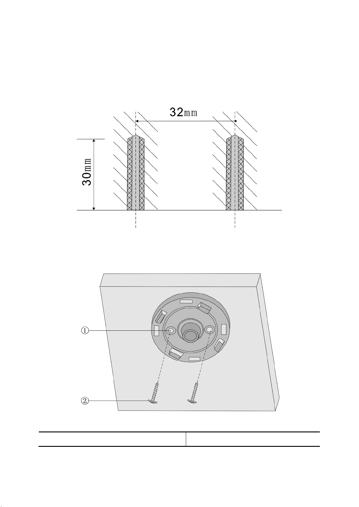
3.4.2 Ceiling-mounted
Step 1
Mark the drilling locations on the ceiling at a distance of 32 mm to each other.
Drill two 6.5 mm holes to a depth of approximately 30 mm
Insert two wall anchors and knock them down into the holes.
WLAN AP Quick Installation Guide
Figure 3 Drill holes locations
Step 2
Affix ceiling mount to ceiling using two screws.
Figure 4 Affix ceiling mount
1:Mounting holes on the circular support 2:Expansion screws
7 CommSky Technologies, Corp.
Page 13
Com m Sky
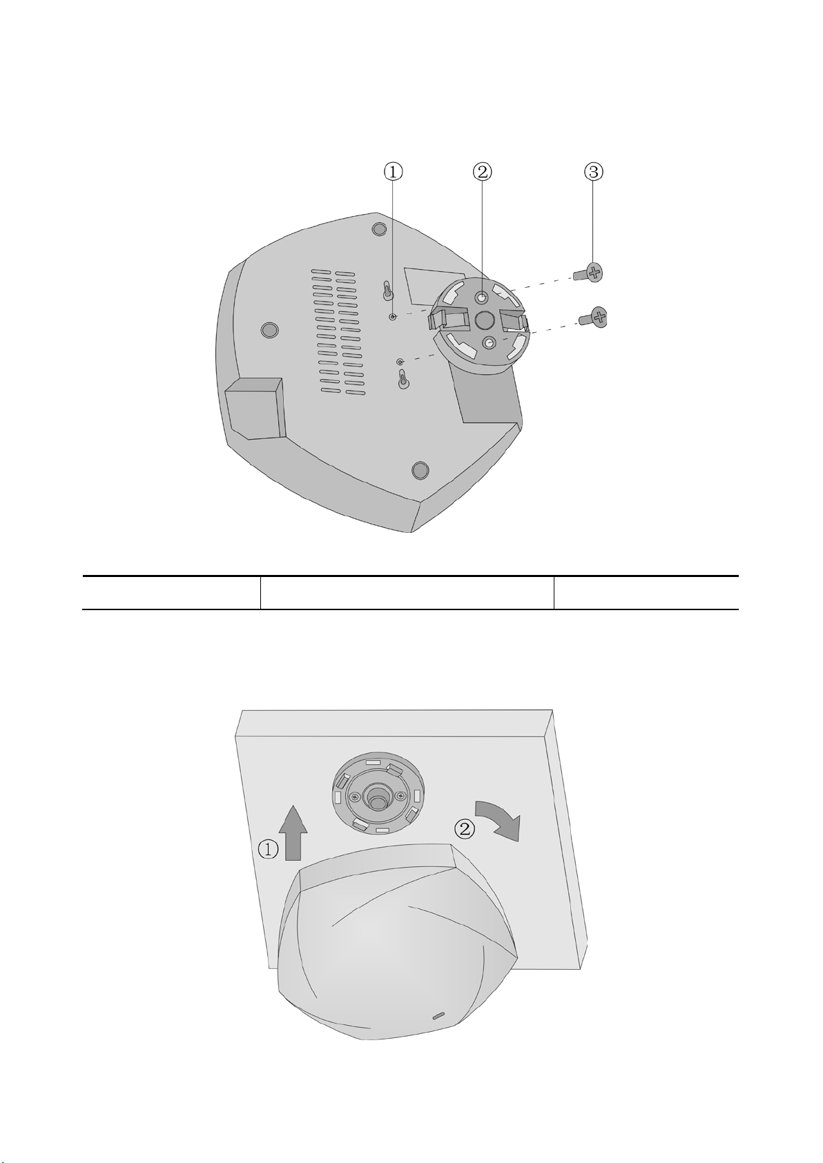
Step 3
Affix hosing bracket to the back of the AP using two screws.
WLAN AP Quick Installation Guide
Figure 5 Affix housing bracket
1:AP mounting holes 2:Circular support mounting holes 3:Pan head screws
Step 4
At a slight counter-clockwise angle, match the housing bracket and the ceiling mount, then rotate the
AP clockwise to secure in place.
Figure 6 Secure AP to ceiling
CommSky Technologies, Corp. 8
Page 14
Power adapter, and power cable are user-supplied.
Com m Sky
WLAN AP Quick Installation Guide
3.5 Connecting the power supply
AP 4600 series products support IEEE 802.3at PoE, supplying power over Ethernet. Customer can
select method of supplying power appropriate to the target network.
Prior to powering up, please ensure that there is a stable supply of power delivered to the equipment.
Regardless of using public utilities, UPS, or private generators, CommSky recommends to centralize
power supplied to the equipment. Such a power network is simple to use, safe to operate, flexibly
configured, and easy to maintain.
The low-voltage power supply uses a single-phase three-wire system.
3.5.1 Pre-power-up checklist
After AP is installed, please verify each of the following items prior to powering up:
If AP uses local power supply, make sure supply has a good connection to the power source.
If AP uses PoE power supply, make sure PoE supply has a good connection to power source
3.5.2 Local power supply
NOTE
Table 1 Power adapter specifications
Item Description
Input 100 VAC to 240 VAC
Output +48V --- 0.8A
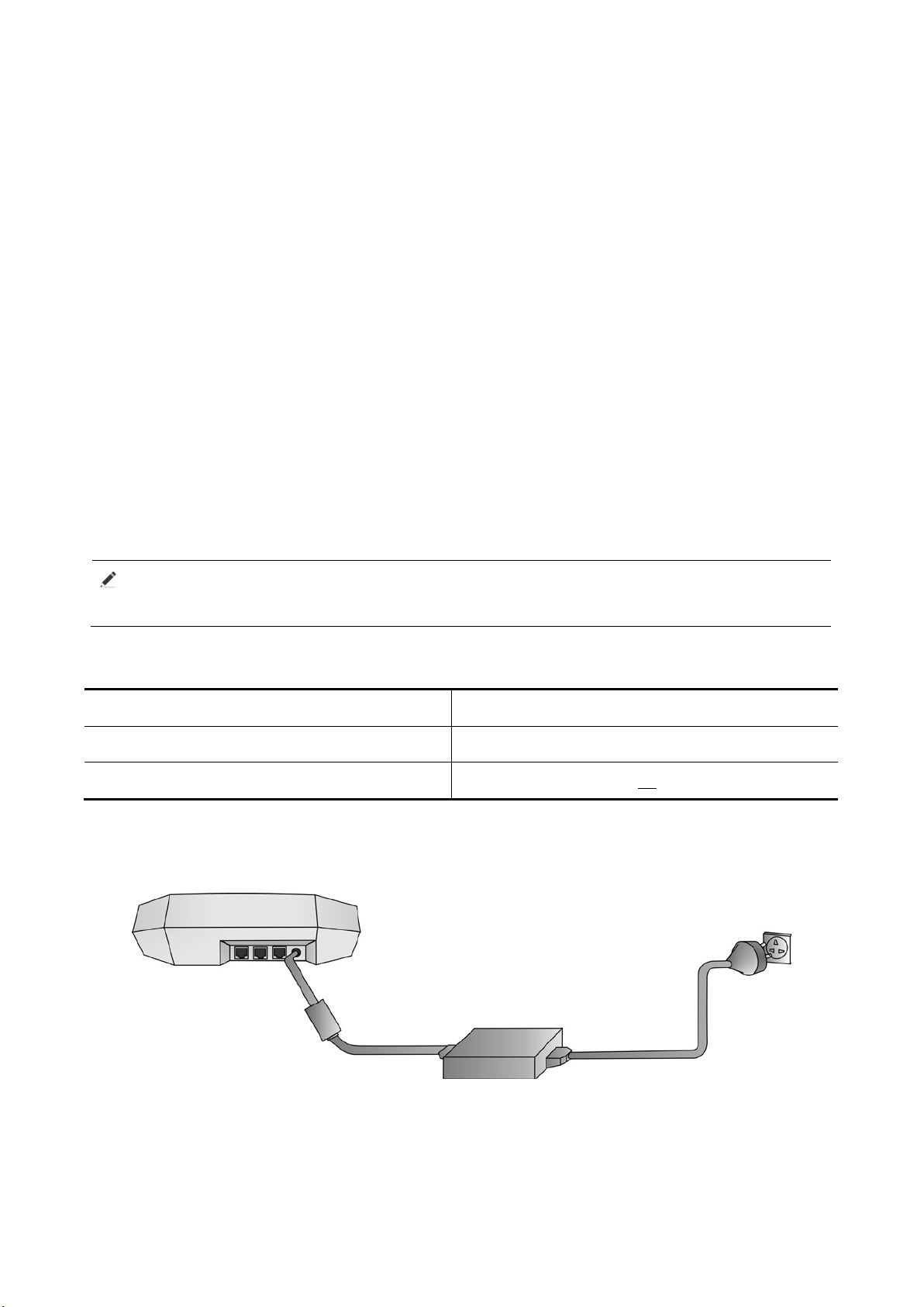
The AP 4600 supports both AC and DC power adapters. You can connect the power port of the AP
to the power source through a power adapter to supply power to the AP.
Figure 7 Local power supply connection
3.5.3 PoE power supply
If uplink device of an AP is a PoE switch, then use an Ethernet cable to directly connect Ethernet
interface on the AP to the PoE device.
9 CommSky Technologies, Corp.
Page 15
1. Do not connect PoE connector to the Console port. Doing so will damage the AP.
Com m Sky
Warning
2. If you use PoE as primary power supply, there is no need to supply power through the power
adapter connector: just connect one end of the network cable to AP’s PoE interface and connect the
other end to the PoE port on the PoE power supply.
4.5.4 PoE Supply Method of Connection
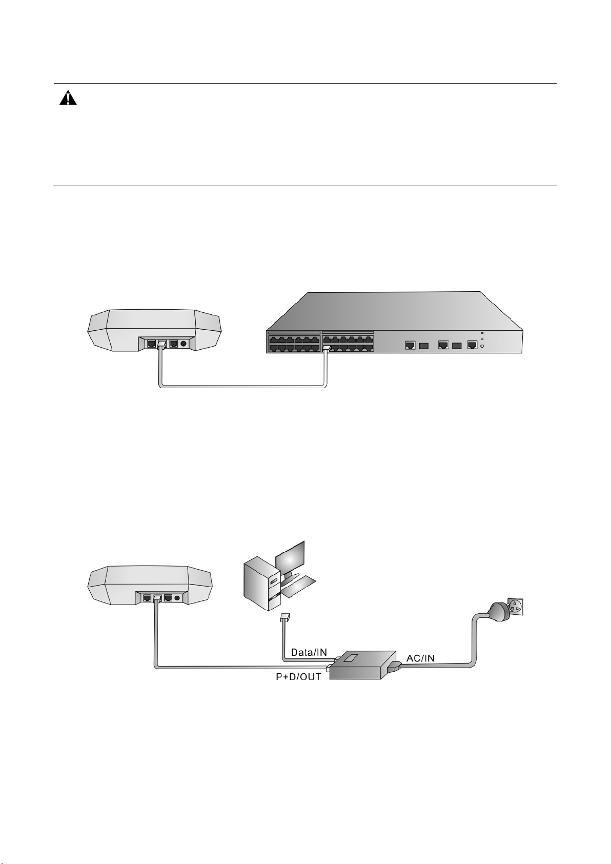
(1)PoE switch as power supply
First, connect one end of the Ethernet cable to AP’s LAN1 port. Next, connect the same cable to the
left most Ethernet ports on the PoE switch. Finally, power up the PoE switch by connecting it to a
local power supply.
WLAN AP Quick Installation Guide
Figure 8 PoE connection
(2)PoE stand-alone power supply
1) Connect one end of Ethernet cable to AP’s LAN1 port; then connect the other end to PoE
P+D/OUT port.
2)Connect Data/IN port on the PoE supply to PC’s ethernet port.
3)After connecting power to PoE supply’s AC/IN port, power up the adapter to start PoE
power delivery.
Figure 9 PoE connection
3.5.5 Post power-up checklist
Once AP is powered up, please make sure AP’s LEDs are operating properly. For the list of AP
LEDs and their purpose, please consult to Section 1: LEDs and Ports.
CommSky Technologies, Corp. 10
Page 16

Configuration method below can only be used on Fat APs. When Thin APs powered up, they
Due to lack of compatibility among different browsers, CommSky recommends using the Google
Com m Sky
WLAN AP Quick Installation Guide
4 Configuration Guide
This section contains a superficial description of how to log on to the per-AP web-based manager.
Please consult related manuals for additional information.
Note
automatically register themselves to the AC. As such, please refer to AC User Guide for
configuring Thin APs.
CommSky Technologies, Corp. designed and implemented three methods to configure AP:
Cloud NMS
Web based Element Manager
CLI
This manual focuses on AP configuration using the web-based Element Manager.
4.1 Required tools
Computer with an ethernet port and web browser;
An Ethernet cable;
A PoE module or PoE switch.
Note
Chrome browser, v20 or later, for best user experience.
4.2 Device default configuration
When factory default HTTP service is enabled on the AP, users can log in to the AP’s web service
interface using default login credential. The default web login information are:
Username:admin;
Password:admin;
IP Address:192.168.0.50。
4.3 Configuration procedure
Step 1:Insert power, wait until Status LED turns blue;
Step 2:After 1 minute, directly connect computer’s Ethernet port to AP’s LAN1 port;
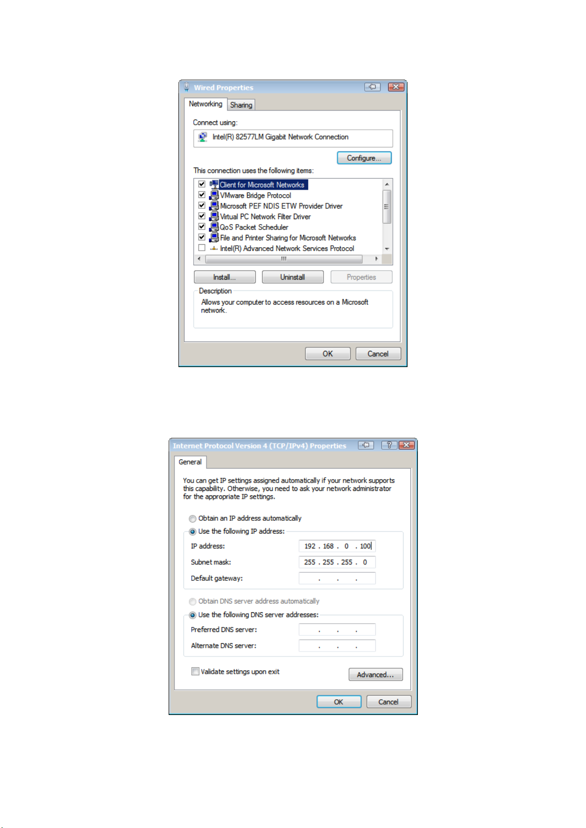
Step 3:change computer’s wired interface to be in the same subnet as the AP, AP’s default
IP address is 192.168.0.50, recommend PC’s management address is set as 192.168.0.100.
Configuration procedure is:【Start】->【Control Panel】->【Network and Internet】->【Network
and Sharing】->【Change Adapter Settings】->【Local Connection】, right click “Properties” to
show the following panel:
11 CommSky Technologies, Corp.
Page 17
Com m Sky
WLAN AP Quick Installation Guide
Figure 5-1 Ethernet Interface
Double click on 【Internet(TCP/IPv4)】to configure static IP address and corresponding network
mask, as show below:
Figure 5-2 Internet Protocol (TCP/IPv4)
CommSky Technologies, Corp. 12
Page 18
During AP configuration, avoid connecting AP to external network. If AP is connected to the
Com m Sky
Warning
external network, please modify AP’s default IP address such that it is in a different subnet than
the external network.
WLAN AP Quick Installation Guide
4.4 Login page
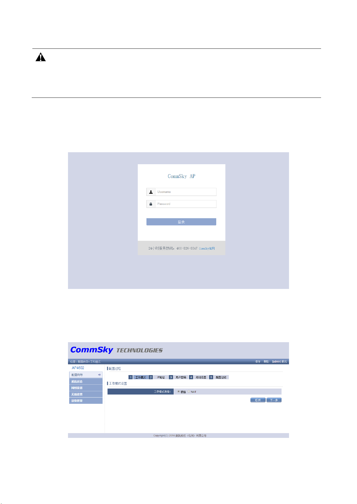
Open web page, enter the following IP address in the browser’s address bar: 192.168.0.50. Browser
will display the following panel, asking user to enter username and password. System default
username is admin, default password is admin。
Figure 5-3 Login Web Page
After entering username and password, click <Log On> button or <Enter> key to perform logon.
Once successfully logged on, user is ready to perform AP configuration.
Figure 5-4 Configuration Page
13 CommSky Technologies, Corp.
Page 19

Com m Sky
WLAN AP Quick Installation Guide
A1 Factory Default Settings
Parameter Default Value
LAN IP Address 192.168.0.50
LAN Network Mask 255.255.255.0
Login Web page username admin
Login Web page password admin
SSID (2.4GHz/5GHz) CommSky_2.4G/CommSky_5G
WPA Pass Phrase 12345678
Telnet Service Enabled
Appendices
HTTP Service Enabled
CommSky Technologies, Corp. 14
Page 20
Com m Sky
WLAN AP Quick Installation Guide
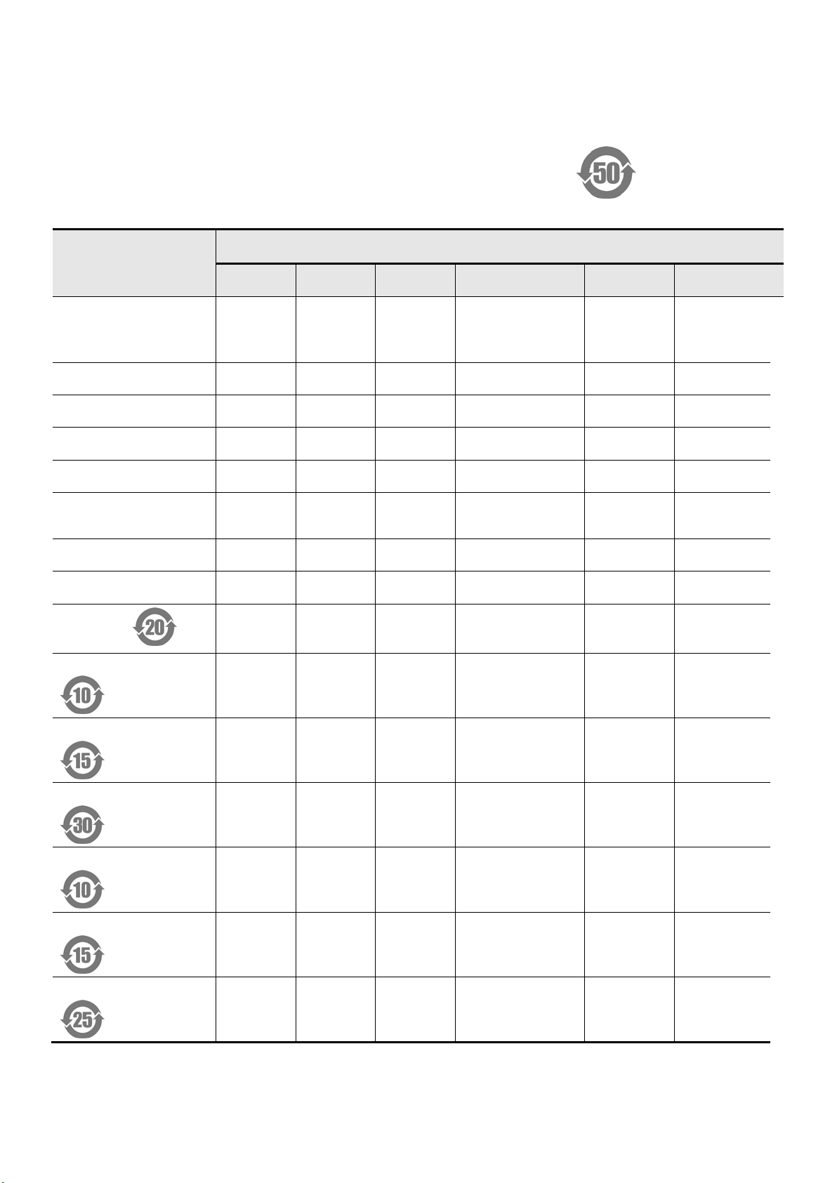
A2 List of Toxic and Hazardous Substances
Parts Name
Chassis / separator /
other metal and
plastic parts
PCB
Wiring
Battery
Fan / fan tray
Power / power
adapter
CF card
Optical module
List of toxic and hazardous substances
Toxic, Hazardous Substances
Pb Hg Cd Cr 6 PBB PBDE
× ○ ○ ○ ○ ○
× ○ ○ ○ ○ ○
× ○ ○ ○ ○ ○
○ ○ ○ ○ ○ ○
○ ○ ○ ○ ○ ○
× ○ ○ ○ ○ ○
○ ○ ○ ○ ○ ○
× ○ ○ ○ ○ ○
Hard drive
Power adapter 1
Power adapter 2
Power adapter 3
Internal power 1
Internal power 2
Internal power 3
× ○ ○ ○ ○ ○
× ○ ○ ○ ○ ○
× ○ ○ ○ ○ ○
× ○ ○ ○ ○ ○
× ○ ○ ○ ○ ○
× ○ ○ ○ ○ ○
× ○ ○ ○ ○ ○
15 CommSky Technologies, Corp.
Page 21
Com m Sky
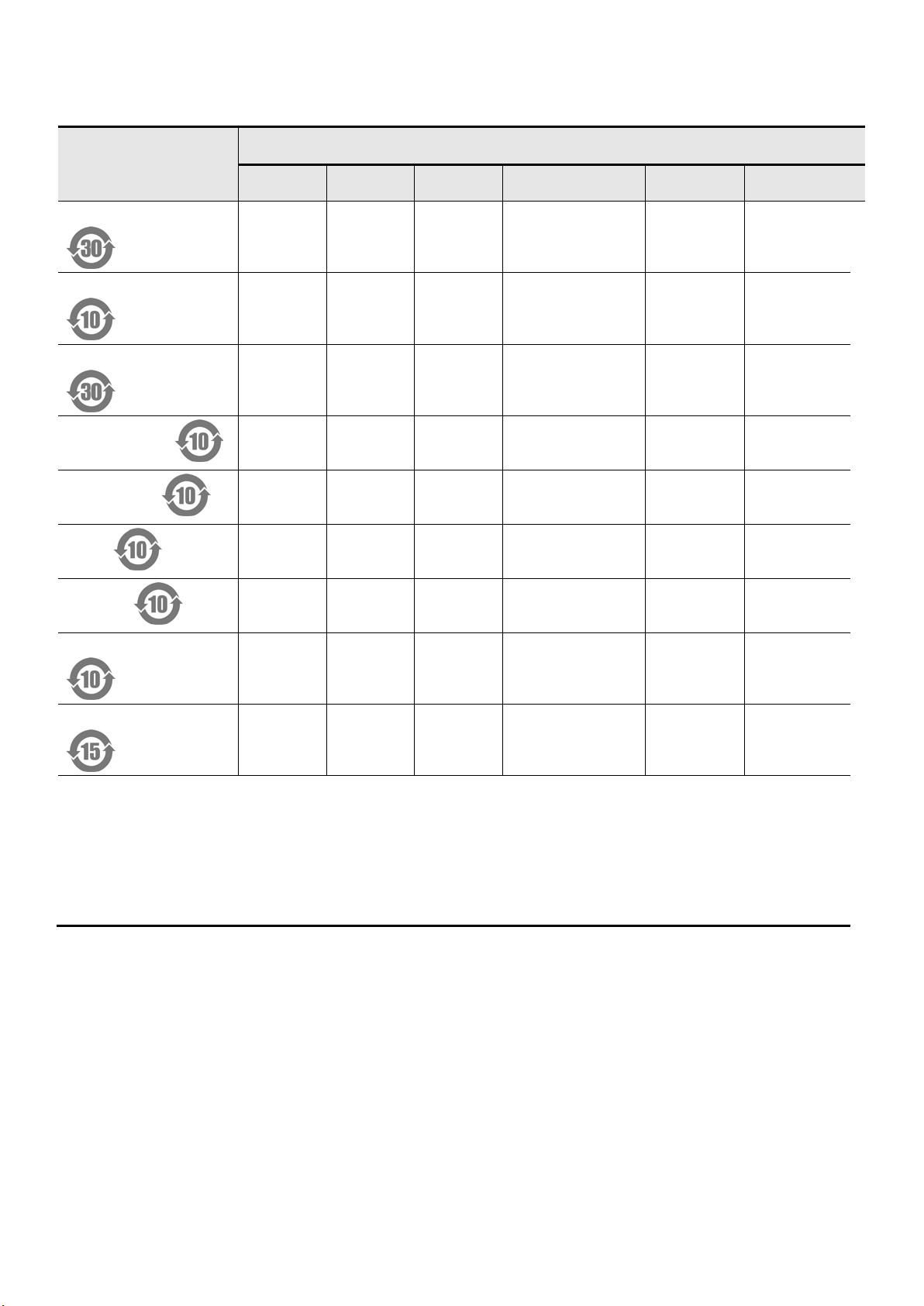
Parts Name
Internal power 4
Redundant power 1
Redundant power 2
WLAN AP Quick Installation Guide
Toxic, Hazardous Substances
Pb Hg Cd Cr 6 PBB PBDE
× ○ ○ ○ ○ ○
× ○ ○ ○ ○ ○
× ○ ○ ○ ○ ○
Video camera
Microphone
RAM
Antenna
Optical Module 1
Optical Module 2
○: Source materials used for this part contains toxic or hazardous substance whose level is lower than
the SJ / T11363-2006 requirements.
×: At least one source materials used for this part contains toxic or hazardous substances whose level
is above the SJ / T11363-2006 prescribed limits.
Note: Environmental aging effect is determined in accordance with the referenced product under
normal operating conditions (such as temperature and humidity).
× ○ ○ ○ ○ ○
× ○ ○ ○ ○ ○
× ○ ○ ○ ○ ○
× ○ ○ ○ ○ ○
× ○ ○ ○ ○ ○
× ○ ○ ○ ○ ○
CommSky Technologies, Corp. 16
Page 22
Com m Sky
WLAN AP Quick Installation Guide
A3 Warranty Card
CommSky Technologies Corporation. Warranty Card
产品名称(Prod. Name):_____________________________________________
型 号(Model Number):_____________________________________________
条形码(Serial Number):
Warranty Terms and Conditions of Service:
CommSky provides high quality and performance network equipment to its customers. CommSky
customers are legally entitled to receive the following support services:
1. Warranty Service:
a. Warranty repairs: A 1 year complementary warranty service starting from date of purchase;
b. DOA exchange: DOA products can be freely exchanged within 30 days of purchase;
c. Power adapter limited warranty:180 days from date of purchase; returned supply adapter
that shows clear damage not due to manufacturing defects, broken cable, or stripped cable are
not replaced. Customer may purchase separately.
Note: Above are limited to the primary product. Packaging, cabling, software, etc. are
excluded from free repair/replacement.
2. Non-warranty service:CommSky will charge repair fees at market rate for any and all non-
warranty repairs.
3. Please present either warranty card or purchase invoice when requesting warranty service. If you
cannot provide an invoice or a valid warranty card, warranty start date will be set to 15 days after the
date of product manufacture.
4. All CommSky exchanged / repaired products are entitled to 180 days of warranty service, counting
from the day of exchange / repair, or continue with existing warranty service, whichever is longer.
5. Warranty does not cover the following:
a. Non-CommSky products;
b. Product whose bar code was torn or altered;
17 CommSky Technologies, Corp.
Page 23

Com m Sky
c. External damage, accidental damage, installation / usage in abnormal environment,
unauthorized product maintenance or modification, external power supply damage, or any other
abnormal damages;
d. Damages due to acts of god: earthquake, tsunami, fire, typhoon, and flood
WLAN AP Quick Installation Guide
6. Contact CommSky technical support at +86-400-826-8847 or website
obtain warranty service.
Warranty Service Locations:
Through your purchasing product agent / distributor, or contact CommSky service personnel.
※ CommSky Technologies Corporation reserves the final right to interpret and modify
contents of this warranty card.
Warning
This device complies with part 15 of the FCC Rules. Operation is subject to the following two
conditions: (1) This device may not cause harmful interference, and (2) this device must accept
any interference received, including interference that may cause undesired operation.
Changes or modifications not expressly approved by the party responsible for compliance
www.commsky.com to
could void the user's authority to operate the equipment.
This equipment has been tested and found to comply with the limits for a Class B digital device,
pursuant to part 15 of the FCC Rules. These limits are designed to provide reasonable protection
against harmful interference in a residential installation. This equipment generates, uses and can
radiate radio frequency energy and, if not installed and used in accordance with the instructions,
may cause harmful interference to radio communications. However, there is no guarantee that
interference will not occur in a particular installation. If this equipment does cause harmful
interference to radio or television reception, which can be determined by turning the equipment
off and on, the user is encouraged to try to correct the interference by one or more of the
following measures:
-- Reorient or relocate the receiving antenna.
-- Increase the separation between the equipment and receiver.
-- Connect the equipment into an outlet on a circuit different from that to which the receiver
is connected.
-- Consult the dealer or an experienced radio/TV technician for help.
CommSky Technologies, Corp. 18
Page 24

Com m Sky
RF exposure statement
This equipment complies with FCC radiation exposure limits set forth for
an uncontrolled environment .
To maintain compliance with FCC’s RF exposure guidelines, this equipment should
be installed and operated with a minimum distance of 20cm between the radiator
and your body.
WLAN AP Quick Installation Guide
CommSky Technologies, Corp.
19
Page 25

Com m Sky
U.S.
California
1-40 8-986 - 950 2 (Fax)
Hang Zhou.China
Copyright © 2016 Com mSk y Techno logies Cor p. All Right s Reserved.
Technologie s
Com m Sky Technologies,Cor p.
4677 Old I ron sides Drive, # 40 0
San t a Clara, California 95054
1-40 8-986 - 950 0 (Office)
CommSky Technologies(Hang Zhou)Co.,Ltd
Jiang Nan Xing Zuo,Unit B2,F6 Chun Xiao Road 529#
Hang Zhou, China
86- 571- 8 7772 116 (Office)
86- 571- 8 6904 001 ( Fax )
 Loading...