

Page 1

639568 • Revision C • November 2008
Page 1 of 6
PWR-COBRA-1 RET Antenna System Quick Installation Guide
Scope
This document briefly describes the installation and operation of the PWR-COBRA Remote
Electrical Tilt antenna system. It is intended to give an overview of basic installation and
operation for experienced antenna users.
Equipment Required
COBRA™ RET capable antennas
Antenna mounting hardware (standard or 0–15° mechanical downtilt kit included with
antenna)
Coaxial cables from BTS to antenna RF ports
CBL-COBRA one feed line and one jumper per additional antenna, or smart bias tees
and jumper cables. Bias tees eliminate the need for the one main RET cable run
PWR-COBRA-1 interface power supply
RS-232 cable (supplied with PWR-COBRA-1)
Laptop or computer with PWR-COBRA software (supplied with PWR-COBRA-1) installed
Installation Instructions
1. Install the antennas using the mounting hardware provided. Record on an Installation
Configuration sheet the antenna sector, model number, serial number, and pointing angle
from 0–360°.
2. Attach the feed lines from the BTS to the antenna RF ports.
3. Attach the female end of the CBL-COBRA homerun data cable to the first antenna
actuator input port. (The homerun cable is the data cable that runs from the base of the
tower to the input of the first antenna in the RET system.)
4. Attach the male end of the CBL-COBRA jumper line to the output port of the first antenna
and route/connect the female end to the second antenna. Repeat this process until all the
antennas are attached to the RET system in a daisy chain configuration. Cap the output
port of the last antenna with the cap cover provided. Please the see note at the end of
this document for cable length recommendations.
5. Attach the male end of CBL-COBRA feed line at the base of the tower to the barrel
connector port on the PWR-COBRA-1 interface power supply.
6. Plug the interface power supply (PWR-COBRA-1) into the power source.
7. Attach the RS-232 cable (or USB-to-Serial adapter cable) to the laptop or computer and
into the PWR-COBRA-1 interface power supply.
8. Boot up the laptop or computer and launch the COBRA™ RET application software.
9. Click on the Scan button (located under the RET/Identification tab) to search for all
antennas connected to the RET system. When the scan is complete, all the antenna
actuators will be listed by their serial numbers (Figure 1).
Andrew, A CommScope Company
3 Westbrook Corporate Center, Suite 900, Westchester, Illinois U.S.A. 60154
U.S.A.: +1 (800) 279-8185 • International: +1 (703) 726-5556
WWW.CommScope.Com
© 2008 CommScope
Page 2

639568 • Revision C • November 2008
Page 2 of 6
Figure 1. RET Device Scan Results.
10. After the device scan has found all the installed antenna actuators, double click on the
serial number for the antenna actuator in the list that is to be configured.
“CONNECTED” should pop up in the Response box in the Selection area.
11. Enter the password Administrator (the password should be entered as shown with A in
upper case and the remaining letters using lower case)Click on Enable. The angle
indicator will move to the current electrical downtilt setting for the antenna.
Important Note:
Every time the Connect button is used, you must also click the Enable
button. If this is not done, errors are likely to result when reading or saving
settings in the RET.
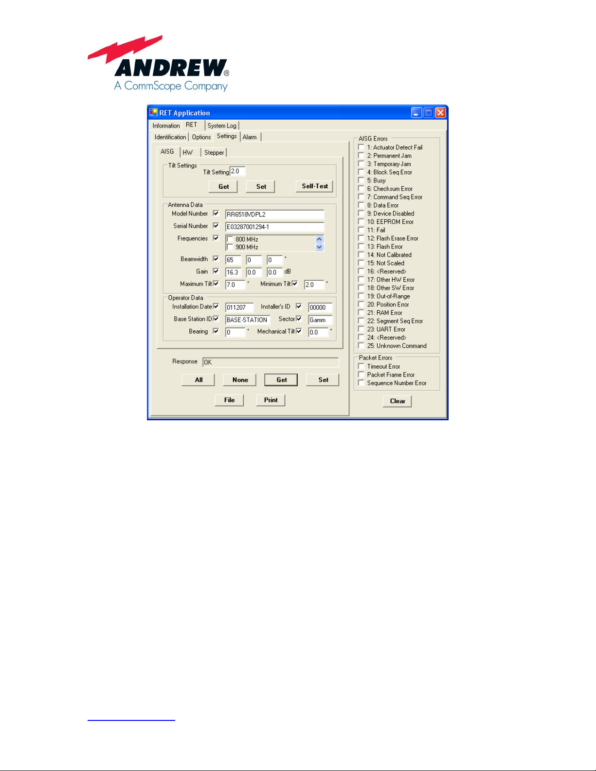
12. Click the Settings tab (located at the top of the screen). At the bottom of the screen, click
on ALL and then click on GET. This will populate the Antenna Data section of the scre en
with information that was programmed into the antenna at the factory (including model
number, serial number, frequency, gain, and the maximum and minimum tilt settings).
The Operator data section will be blank and should be filled in with the information that
was recorded on the Installation Configuration sheet in Step 1 (Figure 2 ).
Andrew, A CommScope Company
3 Westbrook Corporate Center, Suite 900, Westchester, Illinois U.S.A. 60154
U.S.A.: +1 (800) 279-8185 • International: +1 (703) 726-5556
WWW.CommScope.Com
© 2008 CommScope
Page 3
639568 • Revision C • November 2008
Page 3 of 6
Figure 2. Configuring Site Information into the PWR-COBRA Interface for a RET Antenna.
13. To store data in the Operator Data fields, use the information gathered during installation
and also enter the Installation Date, Installer’s Identification (this can be the company or
the individual name), Base Station ID, Sector, Bearing, and the amount of mechanical
downtilt set on the antenna during the installation. Once this information is entered, click
on SET to save this information to the flash memory at the antenna. Repeat this step for
each antenna located on the tower until all parameters are complete.
14. To set the electrical downtilt for each antenna actuator, first double click on the first
antenna serial number shown in the Vendor/Serial Number box on the Identification
screen. Enter the password (the password should be entered using lower case letters),
and then click on Connect and Enable. The Response window should display
CONNECTED. Select the Settings tab then the AISG tab. Enter the desired downtilt in
the Tilt Setting box at the top, then click the Set button. Repeat this step until all
antennas at the site have the desired electrical downtilt setting. See Figure 2.
Andrew, A CommScope Company
3 Westbrook Corporate Center, Suite 900, Westchester, Illinois U.S.A. 60154
U.S.A.: +1 (800) 279-8185 • International: +1 (703) 726-5556
WWW.CommScope.Com
© 2008 CommScope
Page 4

639568 • Revision C • November 2008
15. After all the antenna actuators have been configured and the downtilt settings have been
adjusted to their new values, you may want to generate a record of your work. Go to the
AISG screen shown in Figure 2 to generate a record (a read only XML file will be
generated).
Double click on the serial number of the antenna actuator (on the Identification screen)
you want to create a record on, and then click on File located on the AISG tab screen.
The software will prompt you for the location you wish to store the file on your computer
and for a filename. Typically, the file is named after the site the antennas are installed on
(e.g. GA12345 or TX345). After saving this file, you will then return to the Identification
tab where you can repeat this process with the remaining antenna actuators listed. Each
time you click on File you will be asked Do you want to replace this, click Yes (this will
add the new serial number into the file and will start compiling a list.) Figure 3 shows an
example of a file generated using the process described in this step. These files (XML
format) can be opened/viewed through an Internet browser (Microsoft Internet Explorer).
<?xml version="1.0" encoding="utf-8" ?>
-
<Antenna>
<Settings ID="EM12033901DWDV">
<Field Name="Date" Value="Wed, 12 Nov 2008 15:33:10 GMT" />
<Field Name="Tilt" Value="2.0" />
<Field Name="RET Software Version" Value="V2.3.1 [Build 02Nov07]" />
<Field Name="Antenna Model" Value="RR6518VDPL2" />
<Field Name="Antenna Serial Number" Value="E03287001294-1" />
<Field Name="Antenna Frequency Bands" Value="16" />
<Field Name="Antenna Beamwidth (1)" Value
<Field Name="Antenna Beamwidth (2)" Value="0" />
<Field Name="Antenna Beamwidth (3)" Value="0" />
<Field Name="Antenna Gain (1)" Value="16.3" />
<Field Name="Antenna Gain (2)" Value="0.0" />
<Field Name="Antenna Gain (3)" Value="0.0" />
<Field Name="Maximum Downtilt Angle" Value="7.0" />
<Field Name="Minimum Downtilt Angle" Value="2.0" />
<Field Name="Installation Date" Value="011207" />
<Field Name="Installer Identifier" Value="00000" />
<Field Name="Base Station Identifier" Valu e="BASE-STATION" />
<Field Name="Sector Identifier" Value="Gamm" />
<Field Name="Antenna Bearing" Value="0" />
<Field Name="Installed Mechanical Tilt" Value="0.0" />
<Field Name="Vendor Identifier" Value="EM" />
<Field Name="Controller Model Number" Value="ACT_COBRA_3" />
<Field Name="Controller Serial Number" Value="12033901DWDV" />
<Field Name="Controller Identifier" Value="610198-3S" />
<Field Name="RS-485 Termination" Value="false" />
="65" />
<Field Name="Number of Stepper Motors" Value="1" />
<Field Name="Potentiometer Scaling" Value="612" />
<Field Name="Shaft Gear" Value="40" />
<Field Name="Stepper Motor Resolution" Value="200" />
<Field Name="Worm Resolution" Value="1" />
<Field Name="Number of Smoothing Samples" Value="8" />
<Field Name="Left-Side Orient ation" Value="false" />
<Field
Name="Calibration Current Limit" Value="290" />
Andrew, A CommScope Company
3 Westbrook Corporate Center, Suite 900, Westchester, Illinois U.S.A. 60154
U.S.A.: +1 (800) 279-8185 • International: +1 (703) 726-5556
WWW.CommScope.Com
© 2008 CommScope
Page 4 of 6
Page 5

639568 • Revision C • November 2008
<Field Name="Stepper Current Limit" Value="310" />
<Field Name="Current Sample Duty Cycle" Value="35" />
<Field Name="Stepper Pulse Frequency" Value="500" />
<Field Name="Lower Position" Value="369" />
<Field Name="Center Position" Value="537" />
<Field Name="Present Sweep Count" Value="0" />
<Field Name="Upper Position" Value="706" />
Field Name="Present Mechanical Position" Value="706" />
<
<Field Name="Mechanical Span" Value="101.4" />
<Field Name="Temperature (deg C)" Value="29.0" />
<Field Name="Minimum Temperature (deg C)" Value="23.4" />
<Field Name="Maximum Temperature (deg C)" Value="29.0" />
<Field Name="Motor Voltage (V)" Value="29.938" />
<Field Name="Minimum Motor Voltage (V)" Value="15.392" />
<Field Name
<Field Name="3.3V Logic Voltage" Value="3.328" />
<Field Name="3.3V Minimum Logic Voltage" Value="3.324" />
<Field Name="3.3V Maximum Logic Voltage" Value="3.333" />
</Settings>
</Antenna>
="Maximum Motor Voltage (V)" Value="29.938" />
Figure 3. Site Report File Viewed Using Internet Browser.
Page 5 of 6
For the following Andrew Antennas, Andrew recommends no more than 130 meters of total
data cabling to the last actuator.
MB72RR80VDPALQ_R12 MB72RR65VDPALQ_R12
MB48RR80VDPALQ_R12 MB48RR65VDPALQ_R12
RR6518VDPL2_R RR9017VDPL2_R
RR6518VDUL2_R RR3320VDPL4_R
RR6513VDBL2-R RR9012VDBL2-R
Multiple homerun cables can be used for very demanding installations. Note that for 15 inch
COBRA actuators, Andrew recommends a homerun cable be used for each sector with a
maximum of 3 antennas on a sector.
Andrew, A CommScope Company
3 Westbrook Corporate Center, Suite 900, Westchester, Illinois U.S.A. 60154
U.S.A.: +1 (800) 279-8185 • International: +1 (703) 726-5556
WWW.CommScope.Com
© 2008 CommScope
Page 6

WARRANTY NOTICE
Proper installation, procedures must be followed when
installing and operating RET equipment. Failure to assure
installations are done by properly trained installation
personnel and follow Andrew’s documented procedures
may cause warranty for such products to be void.
Andrew requires that all RET installations be pre-tested
and configured prior to installation. Failure to conduct pretest and pre-installation procedures defined b y Andrew will
void warranty.
SAFETY NOTICE
The installation, maintenance, or removal of an antenna
requires qualified, experienced personnel. Andrew
installation instructions are written for such installation
personnel. Antenna systems should be inspected once a
year by qualified personnel to verify proper installation,
maintenance, and condition of equipment.
639568 • Revision C • November 2008
Page 6 of 6
Andrew disclaims any liability or responsibility for the
results of improper or unsafe installation practices.
Do not install near power
lines. Power lines,
telephone lines, and guy
wires look the same.
Assume any wire or line
can electrocute you.
Andrew, A CommScope Company
3 Westbrook Corporate Center, Suite 900, Westchester, Illinois U.S.A. 60154
U.S.A.: +1 (800) 279-8185 • International: +1 (703) 726-5556
WWW.CommScope.Com
© 2008 CommScope
Do not install on a wet or
windy day or when
lightning or thunder is in
the area. Do not use
metal ladder.
Wear shoes with rubber
soles and heels. Wear
protective clothing
including a
long-sleeved shirt and
rubber gloves.
 Loading...