

Page 1

NVG558 4G-LTE Gateway
User Manual, STANDARD Revision x.1
October 2020
P/N 365-095-35715
Page 2

CommScope copyrights and trademarks
©
2020 CommScope, Inc. All rights reserved.
No part of this content may be reproduced in any form or by any means or used to make
any derivative work (such as translation, transformation, or adaptation) without written
permission from CommScope, Inc. and/or its affiliates (“CommScope”). CommScope
reserves the right to revise or change this content from time to time without obligation on
the part of CommScope to provide notification of such revision or change. ARRIS and the
ARRIS Logo are trademarks of CommScope, Inc. and/or its affiliates. All other trademarks are
the property of their respective owners.
Wi-Fi Alliance®, Wi-Fi®, the Wi-Fi logo, the Wi-Fi CERTIFIED logo, Wi-Fi protected access
(WPA), the Wi-Fi Protected Setup logo, and WMM® are registered trademarks of Wi-Fi
Alliance. Wi-Fi Protected Setup™, Wi-Fi Multimedia™, and WPA2™ are trademarks of Wi-Fi
Alliance.
CommScope provides this guide without warranty of any kind, implied or expressed,
including, but not limited to, the implied warranties of merchantability and fitness for a
particular purpose. ARRIS may make improvements or changes in the product(s) described in
this manual at any time.
The capabilities, system requirements and/or compatibility with third-party products
described herein are subject to change without notice.
®
NVG558 4G-LTE Gateway User Manual STANDARD Revision x.1 2
Page 3

Revision history
Revision Date Summary
x1 October 2020 First issue
NVG558 4G-LTE Gateway User Manual STANDARD Revision x.1 3
Page 4

Table of contents
Chapter 1: Introduction............................................................................ 7
About the NVG500-series Gateways.............................................................................. 7
Chapter 2: Set up the Gateway.................................................................8
Configure Ethernet connections.....................................................................................8
Requirements....................................................................................................... 8
How to use this section....................................................................................... 8
Configure TCP/IP for Windows Vista....................................................................8
Configure TCP/IP for Windows 7, Windows 8, or Windows 10............................9
Configure TCP/IP for macOS................................................................................ 9
Connect to Wi-Fi...........................................................................................................10
Access the web management interface....................................................................... 10
Access online help..............................................................................................12
Navigation with the tab bar...............................................................................13
Chapter 3: How to.................................................................................. 14
Access the Gateway from somewhere else................................................................. 14
Allow an application to bypass the Firewall................................................................ 15
Change the access code............................................................................................... 16
Configure a default server............................................................................................17
Configure IP Passthrough............................................................................................. 18
Create a custom service............................................................................................... 19
Pair a device with the Gateway using WPS................................................................. 20
Restore the Gateway default settings..........................................................................20
Save or restore the configuration................................................................................ 21
Schedule downtime for a network...............................................................................21
Set up Dynamic DNS.................................................................................................... 22
Work with packet filters...............................................................................................23
Chapter 4: Tab and link elements defined...............................................25
Home tab......................................................................................................................25
Login................................................................................................................... 25
Home.................................................................................................................. 25
Device List.......................................................................................................... 27
Alias.................................................................................................................... 28
System tab.................................................................................................................... 30
System Status..................................................................................................... 30
Access Code........................................................................................................30
Restart................................................................................................................ 31
Reset...................................................................................................................32
NVG558 4G-LTE Gateway User Manual STANDARD Revision x.1 4
Page 5

Remote Access................................................................................................... 33
Misc.................................................................................................................... 35
Resources............................................................................................................35
Broadband tab..............................................................................................................36
Broadband Status...............................................................................................37
Broadband Settings............................................................................................39
Connection Settings........................................................................................... 39
Dynamic DNS......................................................................................................40
Routing............................................................................................................... 41
Routing Table......................................................................................................42
Wi-Fi tab....................................................................................................................... 43
Wi-Fi Status........................................................................................................ 43
Wi-Fi Home........................................................................................................ 46
Primary............................................................................................................... 46
Guest.................................................................................................................. 48
Advanced............................................................................................................ 49
MAC Filtering......................................................................................................50
Tools....................................................................................................................51
WPS (Wi-Fi Protected Setup)............................................................................. 53
Schedule............................................................................................................. 54
Wi-Fi security..................................................................................................... 54
Network tab..................................................................................................................55
Network Status...................................................................................................55
Configure (Ethernet LAN)...................................................................................58
Subnets & DHCP.................................................................................................58
DHCP Reservation...............................................................................................60
DHCP Leases.......................................................................................................61
ARP Table............................................................................................................61
UPnP................................................................................................................... 62
Firewall tab................................................................................................................... 62
Firewall Status....................................................................................................63
Level....................................................................................................................63
Port Triggering....................................................................................................64
Port Forwarding..................................................................................................65
Packet Filter........................................................................................................68
Public Subnet Hosts........................................................................................... 69
IP Passthrough....................................................................................................69
DoS Protection................................................................................................... 71
Static NAT........................................................................................................... 73
UPnP................................................................................................................... 73
Access Control....................................................................................................74
Blocking.............................................................................................................. 75
ALG..................................................................................................................... 76
Diagnostics tab............................................................................................................. 76
Troubleshoot.......................................................................................................76
Logs.....................................................................................................................78
NAT Table............................................................................................................79
Tech Support Info...............................................................................................80
NVG558 4G-LTE Gateway User Manual STANDARD Revision x.1 5
Page 6

Cellular tab................................................................................................................... 81
Cellular Statistics................................................................................................ 81
Cellular Settings..................................................................................................82
APN Management.............................................................................................. 83
Chapter 5: Troubleshooting.....................................................................84
Connection issues.........................................................................................................84
No Wireless light................................................................................................84
The Internet is not accessible but the user interface of the gateway is
accessible.......................................................................................................84
LAN Issues.....................................................................................................................84
IP address conflict..............................................................................................85
A wireless device is not locating the gateway................................................... 85
Cannot connect to the Gateway........................................................................86
The wireless signal strength is weak..................................................................86
Cannot set a custom Wi-Fi password................................................................ 87
Diagnostic issues...........................................................................................................88
Ping/Traceroute/DNS query does not respond..................................................88
Status lights.................................................................................................................. 88
NVG558 4G-LTE Gateway User Manual STANDARD Revision x.1 6
Page 7

Introduction
This document describes the installation, features, and configuration of the residential
gateway. The Gateway is your connection to the Internet, and can provide services such as
television, telephone, and wireless Internet.
You can:
■
configure the gateway using the gateway user interface.
■
view information about your connection, set up the gateway, and change connection
settings.
■
see the status of your gateway, and view logs, statistics, and metrics.
Important: Before configuring or administering the Gateway, you must first install
and connect it. See the Quick Start Guide that came with your Gateway for details.
Chapter 1
About the NVG500-series Gateways
The NVG500-series Gateways provide high-speed Internet, flexible home networking, as well
as a professional-grade firewall.
This document covers the model below. Models differ in the broadband interface provided.
■
NVG558: LTE (fixed wireless access)
NVG558 4G-LTE Gateway User Manual STANDARD Revision x.1 7
Page 8

Set up the Gateway
Use this chapter to:
■
Configure your computer's TCP/IP settings, if necessary
■
Access the web-based management interface
■
Access online help
Configure Ethernet connections
If you connect your computer to the Gateway using an Ethernet connection, you may have
to configure your computer’s TCP/IP settings. While you can configure your computer's Wi-Fi
setting using the same instructions, you can usually connect using default settings.
Requirements
Chapter 2
Make sure you have the following before attempting to configure your Ethernet connection:
■
Computer with Ethernet interface.
■
Ethernet cable.
■
IP address, subnet, gateway, and DNS information for installations not using DHCP.
How to use this section
The following list shows the procedures for modifying the TCP/IP settings on the computer.
The procedure is slightly different depending on the operating system that you are using.
Please ensure you are using the correct steps for the operating system on your computer.
Follow the links below for instructions to configure your Ethernet connection on your
operating system.
■
Configure TCP/IP for Windows Vista (page 8)
■
Configure TCP/IP for Windows 7, Windows 8, or Windows 10 (page 9)
■
Configure TCP/IP for macOS (page 9)
Configure TCP/IP for Windows Vista
1. Open the Vista Control Panel.
2. Double-click Network and Sharing Center to display the Network and Sharing Center
Window.
NVG558 4G-LTE Gateway User Manual STANDARD Revision x.1 8
Page 9

Chapter 2: Set up the Gateway
3. Click Manage network connections. If prompted for a connection, choose Local Area
Connection.
The Network Connections window appears.
4. Double-click the Local Area Connection to open the Properties window:
Note: If Windows requests permission to continue, click Continue.
5. Double-click Internet Protocol Version 4 (TCP/IPv4) to configure TCP/IPv4.
Note: If your service provider requires TCP/IP version 6, double-click Internet
Protocol Version 6 (TCP/IPv6) to configure TCP/IPv6.
The TCP/IP properties window for the version you selected appears.
6. For either TCP/IPv4 or TCP/IPv6, select Obtain an IP address automatically and Obtain
DNS server address automatically, unless instructed otherwise by your service provider.
7. Click OK to accept the new settings and close the Properties window.
Configure TCP/IP for Windows 7, Windows 8, or Windows 10
1. Click the Start menu and type network and sharing into the Search box.
2. Select Network and Sharing Centerwhen it appears.
3. Click Change adapter settings from the left-side menu.
4. Right-click on your local area connection icon and select Properties to open the
Properties window.
5. Select Internet Protocol Version 4 (TCP/IPv4) and click Properties to configure TCP/IPv4.
Note: If your service provider requires TCP/IP version 6, select Internet Protocol
Version 6 (TCP/IPv6) and click Properties to configure TCP/IPv6.
The TCP/IP properties window for the version you selected appears.
6. For either TCP/IPv4 or TCP/IPv6, select Obtain an IP address automatically and Obtain
DNS server address automatically, unless instructed otherwise by your service provider.
7. Click OK to accept the new settings and close the Properties window. Then click Close to
back out of the remaining setup screens.
Configure TCP/IP for macOS
1. Open System Preferences, either by choosing System Preferences from the Apple menu
or by clicking the System Preferences icon in the dock.
2. Click the Network icon.
3. Choose Automatic from the Location drop-down menu, and Built-in Ethernet from the
Show menu.
4. Choose the TCP/IP tab, if necessary.
If you are using TCP/IPv4, go to step 5.If your service provider requires TCP/IPv6, go to
step 8.
5. Choose Using DHCP from the Configure IPv4 menu.
NVG558 4G-LTE Gateway User Manual STANDARD Revision x.1 9
Page 10

6. If necessary, click the Renew DHCP Lease button.
7. Close the System Properties application.
TCP/IPv4 configuration is completed.
8. If you are using TCP/IPv6, click Configure IPv6 near the bottom of the previous window.
9. Choose Automatically from the Configure IPv6 drop-down menu and click OK.
10. Close the System Properties application.
Connect to Wi-Fi
The Gateway is compatible with nearly all Wi-Fi devices.
Before you start, locate the label on the base of the Gateway - the label provides
information you need to connect to the Gateway, including network name (SSID) and
passphrase. Alternatively, use your mobile device to scan the Wi-Fi QR code label on the side
of the Gateway.
1. Find and select your Wi-Fi connection icon in the menu bar or system tray.
The location and appearance of the icon are system-dependent.
2. Select the Wi-Fi network whose name matches the SSID name on your Gateway's label.
It may take several seconds for your SSID to appear in the list.
Chapter 2: Set up the Gateway
Important: In high-density dwellings, there may be a number of networks with
very similar names. Make sure you choose the network whose name exactly
matches the name on your Gateway's label.
3. When prompted, enter the password from your Gateway's label.
After a few seconds, your device should indicate a successful connection.
If you cannot connect, check the following.
If... Then...
You cannot see the SSID
You can see the SSID but
cannot connect
■
Make sure the Gateway is powered up.
■
If the Wi-Fi light is not green (steady or flashing), go to the
Primary (page 46) screen and enable Wi-Fi.
■
Proceed to A wireless device is not locating the gateway
(page 85).
Proceed to Cannot connect to the Gateway (page 86).
Access the web management interface
Before you start, connect your device to the Gateway using either Ethernet or Wi-Fi.
1. Open a Web browser, such as Firefox or Chrome, from any computer connected to the
Gateway.
NVG558 4G-LTE Gateway User Manual STANDARD Revision x.1 10
Page 11
2. Enter http://myrouter in the Location text box.
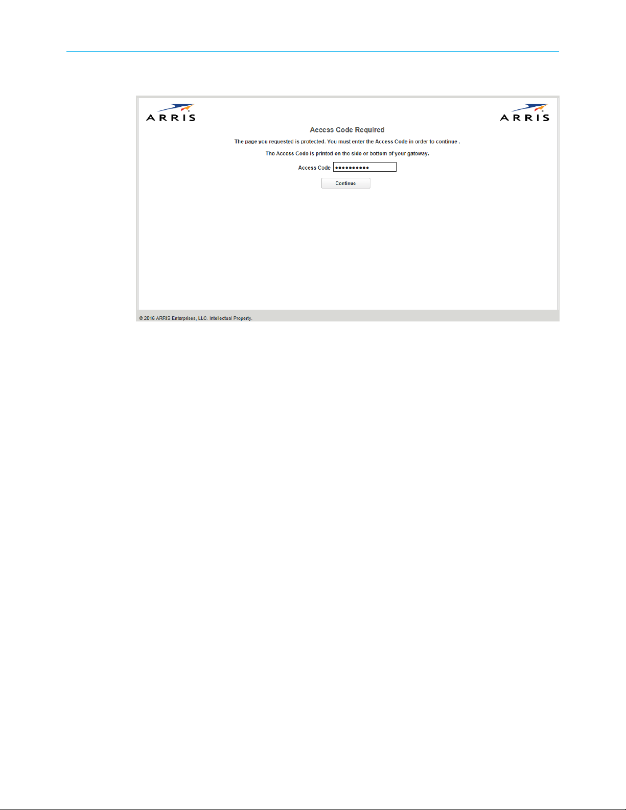
You may be prompted to log in upon accessing certain links.
Chapter 2: Set up the Gateway
3. Enter the access code where prompted.
The default access code is printed on a label on the bottom of the Gateway.
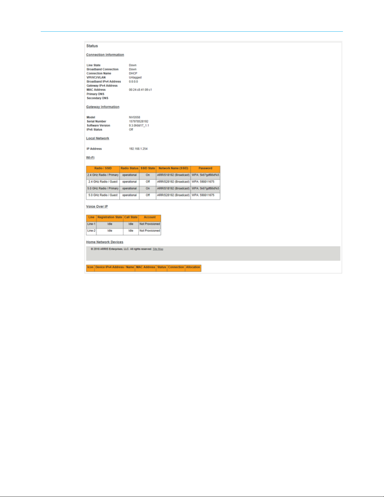
The Main page opens and provides summary information of the system.
NVG558 4G-LTE Gateway User Manual STANDARD Revision x.1 11
Page 12
Chapter 2: Set up the Gateway
4. Check to make sure the Broadband LED on your Gateway is lit GREEN to verify that the
Ethernet WAN connection to the Internet is active.
Access online help
Online help for the Gateway is available on the right side of every web page.
■
Click Show Help to display the information:
NVG558 4G-LTE Gateway User Manual STANDARD Revision x.1 12
Page 13
■
Click Hide Help to turn the information off (the default).
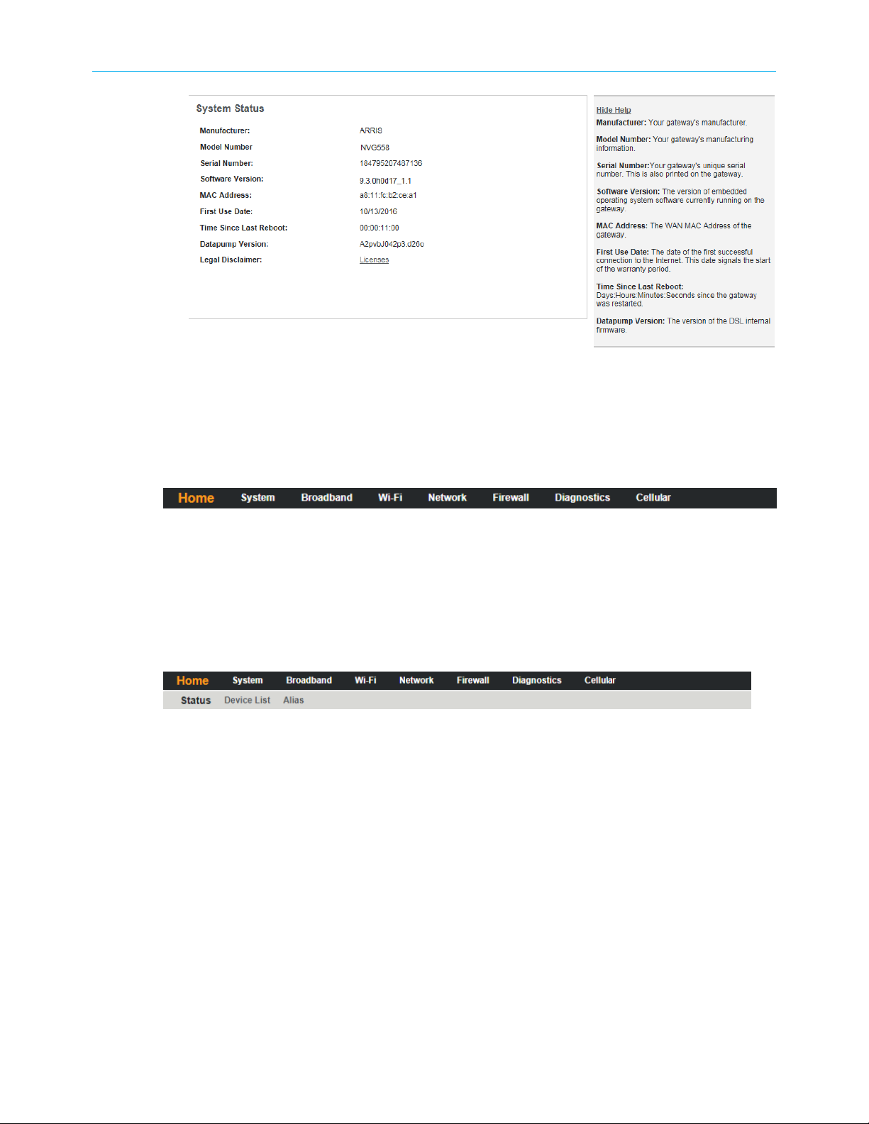
Navigation with the tab bar
The tab bar is located at the top of every page and provides navigation for configuration,
maintenance or monitoring.
Chapter 2: Set up the Gateway
Selecting a tab provides access to pages with a Links bar that allow managing or configuring
several features of the Embedded Software. Each tab is described in its own section.
Element navigation with the links bar
Select a tab bar element to open a links bar beneath the tab bar and the first of the links
pages, usually the status of the element chosen. Use the links to navigate to the pages for
configuration of features displayed on the page.
NVG558 4G-LTE Gateway User Manual STANDARD Revision x.1 13
Page 14
How to
Use these procedures to perform common functions.
Access the Gateway from somewhere else
You can use Remote Access to access the configuration pages as if you were on the home
network.
▶
To enable remote access:
1. Click the System tab, then Remote Access.
The Remote Access screen displays.
Chapter 3
2. Type a password in the Password field.
The password must be at least 8 characters long, and include at least two of the
following types of characters:
■
Alphabetic (letter) characters
■
Numeric (number) characters
■
Special characters (! @ \# $ % ^ & \* and so on)
3. Set a custom port number for secure HTTP access to the Gateway remote access session
in the Port to Use field.
NVG558 4G-LTE Gateway User Manual STANDARD Revision x.1 14
Page 15

Chapter 3: How to
4. Optional: Set an inactivity timeout and duration to minimize the risk of unattended
remote access.
5. Click the radio button that describes the type of remote access to allow:
■
Read-Write
■
Read-Only
6. Optional: Use the Access List fields to restrict which IP addresses can access the Gateway
remotely.
■
One specific IP address: put the same IP address in both the From and To fields. Do
this if you know what IP address the remote device has.
■
IP address range: put the low address in the From field, and the high address in the
To field. Do this if you know what network the remote device uses, but not the exact
IP address.
■
Any IP address: leave the From and To fields blank. Do this only if you cannot find the
IP address or range, because this choice leaves your Gateway open to access from
anywhere.
7. Click Add entry to access list, then repeat step 6 to add more IP addresses or ranges.
8. Click the Enable button.
The Gateway updates the Remote Access page and displays:
■
The current remote access settings
■
Shows the URL that a remote access client must use to connect to the remote access
session
■
Provides a button for ending the remote access session.
9. The remote access client will need to connect to the URL shown on the Remote
Access page, and will need to log in with the user name shown and with the password
configured when access was enabled.
10. To end (disable) an existing remote access configuration, click the Disable button at the
bottom of the page.
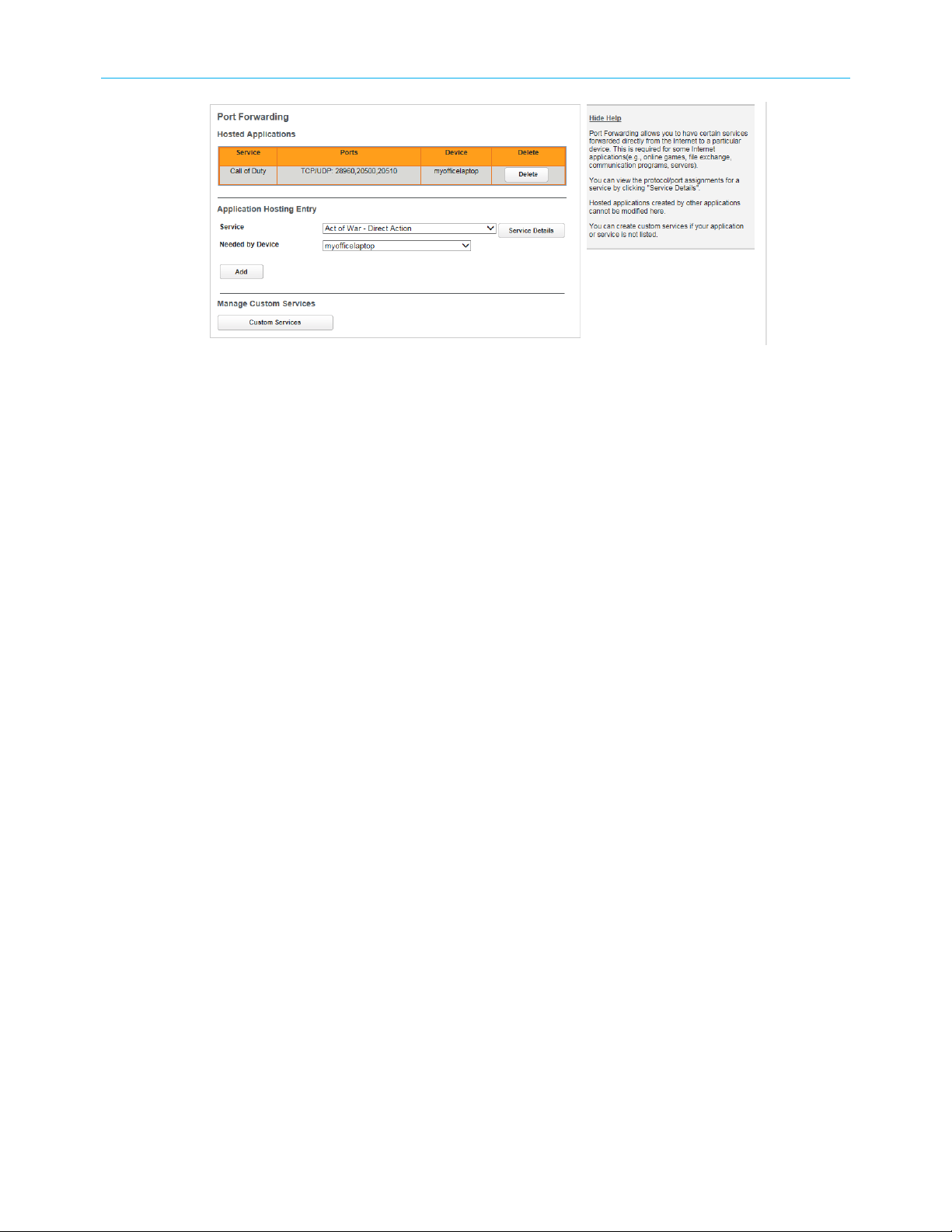
Allow an application to bypass the Firewall
Port Forwarding allows applications and games, that require access to the Internet, to
bypass the Firewall. Choose from a pre-defined list, or create a custom service.
1. In the Firewall tab, click Port Forwarding.
The Port Forwarding page displays:
NVG558 4G-LTE Gateway User Manual STANDARD Revision x.1 15
Page 16
Chapter 3: How to
2. Click the Service drop-down, and choose your application from the list.
If your application is not in the list, proceed to Create a custom service (page 19).
3. Choose the device using this application from the Needed by Device drop-down.
4. Click Add.
The Gateway adds the application to the Hosted Applications list at the top of the page. To
remove an application, click the Delete button next to that application.
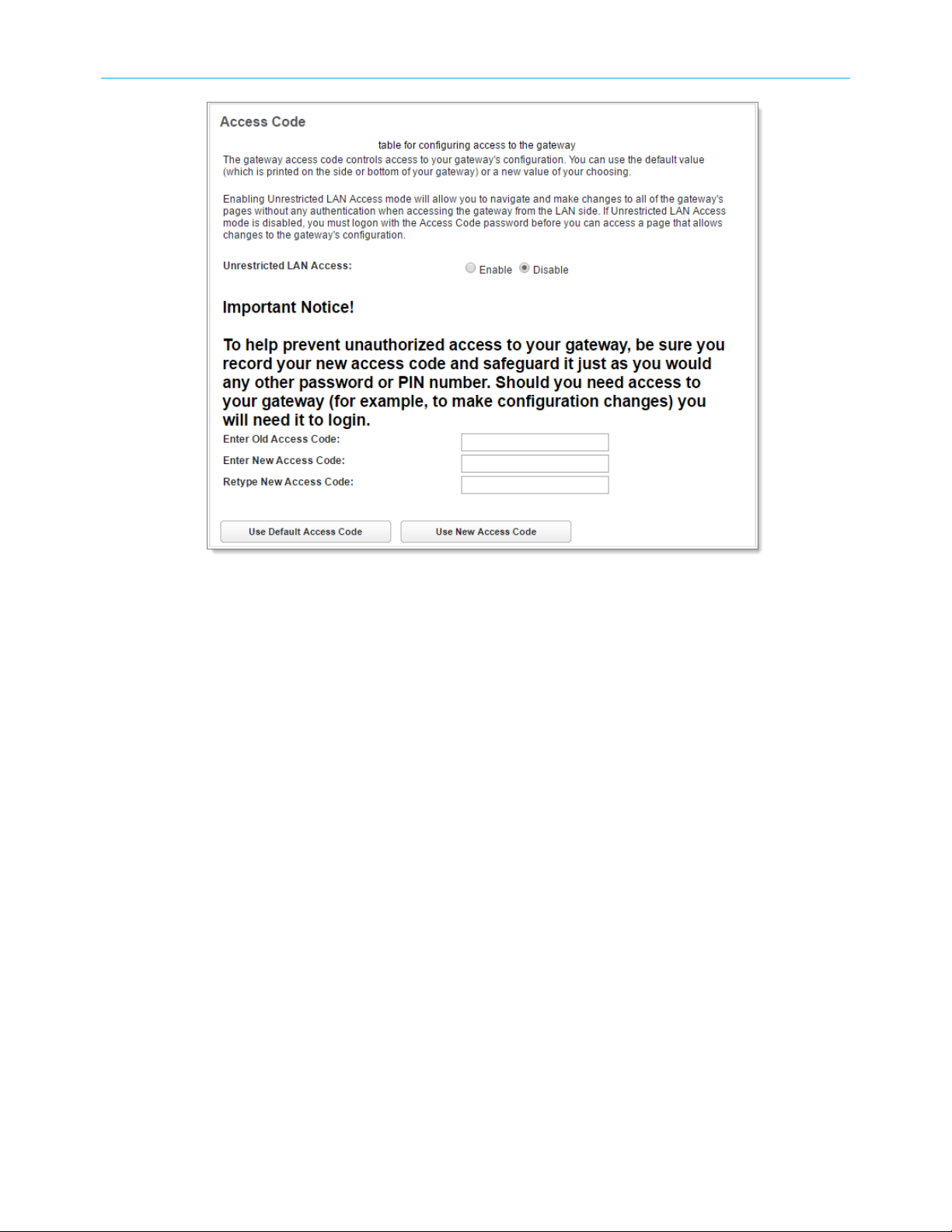
Change the access code
You can change the access code required to access the Gateway configuration.
The password must be between 8 and 20 characters long, and must include characters from
at least two of these categories:
■
Alphabetic (letter) characters
■
Numeric (number) characters
■
Special characters (! @ \# $ % ^ & \* and so on)
▶
To make a change:
1. In the System tab, click Access Code.
The Access Code page displays.
NVG558 4G-LTE Gateway User Manual STANDARD Revision x.1 16
Page 17
Chapter 3: How to
2. Make changes as needed:
■
To change the access code: enter the old access code, the new access code, and a
confirmation of the new access code, and click the Use New Access Code button.
The new access code takes effect immediately.
■
To return to the original default access code: click the Use Default Access Code
button.
■
To return to the last saved Access Code configuration, click the Cancel button.
Configure a default server
You can forward unexpected or unknown incoming IP traffic to a single default host on your
LAN.
Enable the default server for certain situations:
■
Where you cannot anticipate what port number or packet protocol an in-bound
application might use. For example, some network games select arbitrary port numbers
when a connection is opened. With NAT on in the gateway, these packets are normally
discarded.
■
For all unsolicited traffic to go to a specific LAN host.
▶
To configure a default server:
1. Choose the Firewall IP Passthrough link.
The IP Passthrough page displays.
2. Choose Default Server from the Allocation Mode pull-down menu.
NVG558 4G-LTE Gateway User Manual STANDARD Revision x.1 17
Page 18
Chapter 3: How to
The IP Passthrough page displays the Default Server fields:
3. Choose the device on the home network to receive traffic directed to the Gateway's
public IP address.
If the device is connected, find and click its address in the Choose from List field. If the
device has not connected, type its hardware (MAC) address into the Manual Entry input
field.
4. Click Save.
Changes take effect immediately.
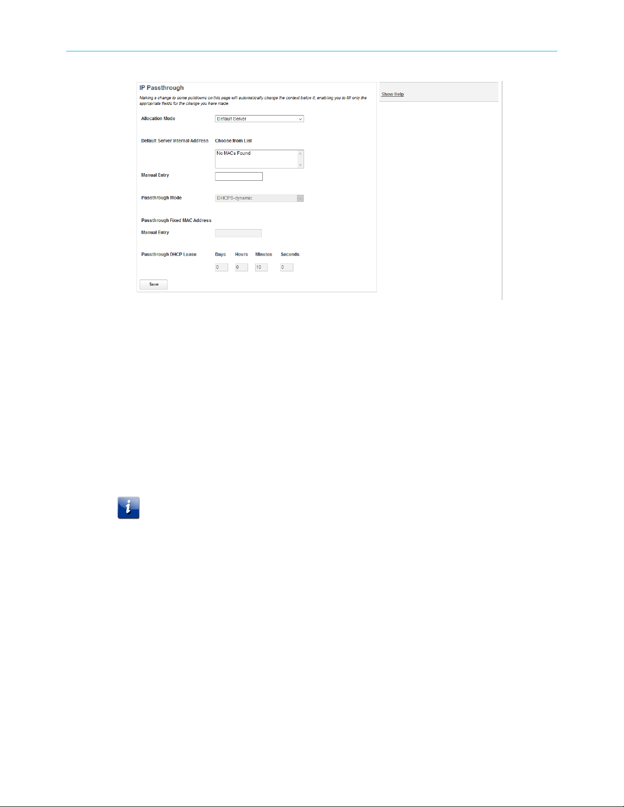
Configure IP Passthrough
The Gateway can pass all incoming traffic to a specific LAN-side client.
Important: Because both the Gateway and the passthrough host use the same IP
address, the Gateway rejects new sessions that conflict with existing sessions. If
two tunnels go to the same remote endpoint, such as a VPN access concentrator,
the first one to start the IPSec traffic will be allowed; the second one, because it is
indistinguishable from the WAN fails.
1. Click the Firewall IP Passthrough link.
2. Choose Passthrough from the Allocation Mode pull-down menu.
3. Choose how the Gateway assigns the public IP address to the passthrough client from
the Passthrough Mode pull-down menu:
■
DHCPS-dynamic: Assign to the first client gateway to renew its DHCP lease, if the
public IP address is available. No further configuration of the passthrough mode is
required.
■
DHCPS-fixed: Choose the gateway. If the gateway has already connected, find and
click the gateway address in the Choose from List field. If the gateway has not
connected, you may type its hardware (MAC) address in the Manual Entry input
field.
NVG558 4G-LTE Gateway User Manual STANDARD Revision x.1 18
Page 19
■
Manual: Manually assign the public IP address and the service provider’s network
mask and default gateway values to the client gateway on the network. No further
configuration of the passthrough mode is required.
Manual mode requires statically configuring your PC. With Manual mode, you
configure the TCP/IP Properties of the LAN client PC you want to be the IP
Passthrough client. You then manually enter the WAN IP address, gateway address,
and so on that matches the WAN IP address information of your ARRIS gateway. This
mode works the same as the DHCP modes; unsolicited WAN traffic will get passed to
this client. The client is still able to access the Gateway and other LAN clients on the
192.168.254.x network, etc.
4. Enter an optional custom passthrough lease time in the Passthrough DHCP Lease fields.
5. Click Save, for changes to take effect upon restart.
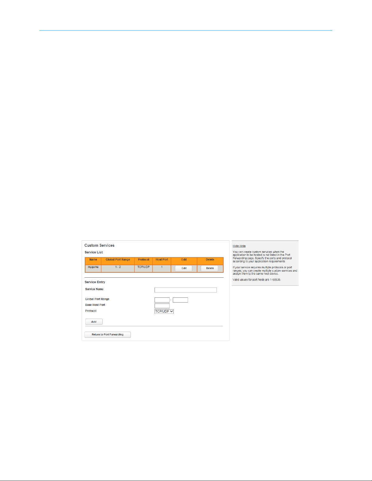
Create a custom service
If no pre-defined Port Forwarding service is available for your application, you can create a
custom service.
Chapter 3: How to
Obtain the ports and protocol type needed for your application. This information should be
in the application's help, or on a support page on the vendor's website.
1. From the Port Forwarding page, click Custom Services.
The Custom Services page displays.
2. Enter the name of your application in the Service Name field.
3. Enter the port range (low port number first) in the Global Port Range fields.
4. Enter the host port number in the Base Host Port field.
5. Select the protocol from the Protocol drop-down: TCP, UDP, or Both.
6. Click Add.
The Gateway adds an entry to the Custom Services list with the entered data.
7. Verify the new custom service against the information supplied by the application
vendor. Click Edit, if required, to make any changes.
8. Click Return to Port Forwarding.
NVG558 4G-LTE Gateway User Manual STANDARD Revision x.1 19
Page 20
Chapter 3: How to
You can now add your custom service using the Port Forwarding page.
Pair a device with the Gateway using WPS
Many wireless devices support Wi-Fi Protected Setup (WPS) method of pairing with the
Gateway. Entering a passphrase is not required.
▶
To pair a device using WPS:
1. On the device, activate WPS. Some devices use a menu entry, others have a WPS button.
2. On the Gateway, press and hold the WPS button until the Wi-Fi light flashes amber.
3. Monitor the Gateway Wi-Fi light and any indicators on the device you are trying to pair.
Pairing may take several minutes.
The Gateway and device automatically connect.
If the Gateway and device do not connect:
■
If the Gateway Wi-Fi light flashes red for 30 seconds, this indicates a timeout or some
other error. Retry the pairing procedure.
■
Try swapping steps 1 and 2 (start WPS on the Gateway first).
■
If you have selected the 5 GHz radio on the WPS page, and the device supports only 2.4
GHz, change the setting to use the 2.4 GHz radio for WPS pairing.
Restore the Gateway default settings
You can reset some Gateway components, or the entire Gateway, to factory defaults.
1. Click the System tab, then choose the Reset link.
The Reset page displays.
2. Click one of the Restore buttons:
■
Click Default Wireless Settings to restore just the Wi-Fi settings.
NVG558 4G-LTE Gateway User Manual STANDARD Revision x.1 20
Page 21
■
Click Default Firewall Settings to restore just the Firewall settings.
■
Click Factory Defaults to restore the entire Gateway to factory default settings.
3. If you have a saved configuration, proceed to Save or restore the configuration
(page 21) to reload it.
Save or restore the configuration
When everything is working properly, or before experimenting with system settings, you
should save the configuration. You can then reload it if necessary.
▶
To save the current configuration:
1. Click the System tab, then choose the Reset link.
The Reset page displays.
Chapter 3: How to
2. Click Save.
Your browser downloads the configuration file. Most computers automatically save to
the Downloads folder.
3. Move the file to a folder where you can find it, if needed.
▶
To restore a saved configuration:
4. Click Choose File.
Your browser prompts you for the name and location of the saved configuration file.
5. Locate the saved configuration, and click OK in your browser.
The Reset page displays the chosen configuration file name.
6. Click Load to load the configuration file.
The Gateway loads the saved configuration, then restarts to apply the changes.
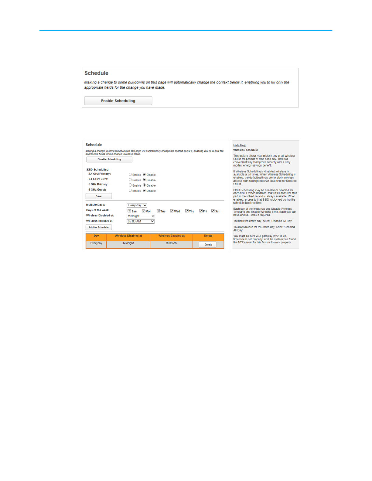
Schedule downtime for a network
Use the Schedule page to disable a Wi-Fi network during certain times of day.
NVG558 4G-LTE Gateway User Manual STANDARD Revision x.1 21
Page 22
Chapter 3: How to
▶
To schedule the dates and times to disable a Wi-Fi network:
1. Click the Wi-Fi tab, then Schedule.
The Schedule page displays:
2. Click Enable Schedule.
The Schedule page displays more information as shown below. The button changes to
Disable Schedule, and can now be used to return to the original display.
3. In SSID Scheduling, select Enable for Wi-Fi scheduling or Disable to forgo Wi-Fi
scheduling for that SSID (wireless is available on that SSID at all times). You can enable
some networks and disable others.
4. In the middle pane date/time resolution fields, select:
■
Multiple Days: Pre-selected configurations for the Days of the week checkboxes.
Choose between Every day, Weekdays, and Weekends.
■
Days of the week: Set the checkboxes as desired. You can override the Multiple Days
selections.
■
Enable/Disable Times: The range of times to disable the networks.
5. Click Add to Schedule.
The schedule selections appear in tabular form in the bottom pane. Click Delete to
remove the item from the schedule.
6. Repeat steps 4 and 5 to add more scheduled downtime. You can do this to, for example,
schedule non-contiguous blocks of downtime.
Set up Dynamic DNS
If you own a domain name that you want to associate with your Gateway, you can use a
Dynamic DNS service.
NVG558 4G-LTE Gateway User Manual STANDARD Revision x.1 22
Page 23
You need an account with one of the listed Dynamic DNS services
To configure Dynamic DNS:
1. Click the Broadband tab, then choose the Dynamic DNS link.
The DynDNS page displays.
Chapter 3: How to
2. Choose On from the Enable DynDNS drop-down list box.
3. Choose your dynamic DNS provider from the Provider drop-down.
4. Enter the credentials for your account at your dynamic DNS provider.
5. Click Save.
Work with packet filters
Follow these steps to work with packet filters.
1. Click the Firewall Packet Filter link.
The Packet Filter page displays.
2. Click Enable/Disable Packet Filters to globally turn filters on or off.
3. Click Add a ‘Drop’ Rule or Add a ‘Pass’ Rule to select the type of packet filter rule.
■
A drop rule blocks matching packets.
■
A pass rule forwards matching packets.
NVG558 4G-LTE Gateway User Manual STANDARD Revision x.1 23
Page 24
Chapter 3: How to
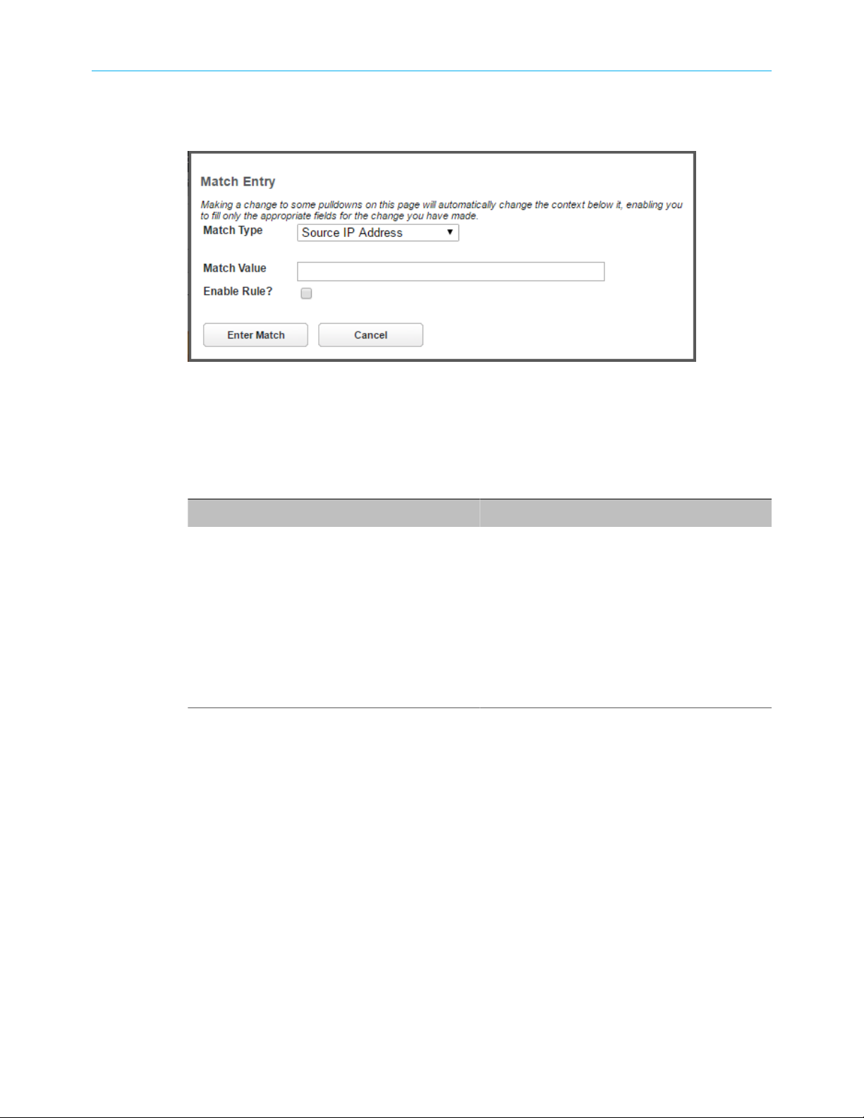
4. Click Add Match to enter the source IP address or destination IP address this filter will
match on.
The Match Entry dialog displays.
As you create new matches, the list items change. There can only be one match from
each match type for a given rule. Match types like Source Port, Destination Port, and TCP
Flags are only available if other matches (for example, Protocol =TCP) have previously
been created.
5. Select a protocol, if necessary, from the pull-down menu: ICMP, TCP, UDP, or None to
specify any another IP transport protocol.
If you chose... Enter...
by number Protocol by number
by name Protocol by name
ICMP ICMP Type as another match
TCP TCP flags, source ports, and destination
ports as other matches
Source Port The port number to match
Destination Port The port number to match
6. Click Enter Match when finished configuring the filter.
The Gateway adds the filter to the Packet Filter list.
NVG558 4G-LTE Gateway User Manual STANDARD Revision x.1 24
Page 25
Tab and link elements defined
The following sections provide detailed information about each of the tabs and links within
the NVG500-series 9.3.0 build.
Home tab
Links available on the Home tab provide an overview of the gateway configuration and
access to pages which allow configuration of the most commonly needed settings.
Select the Home tab to access the Home page and the Home links bar.
Chapter 4
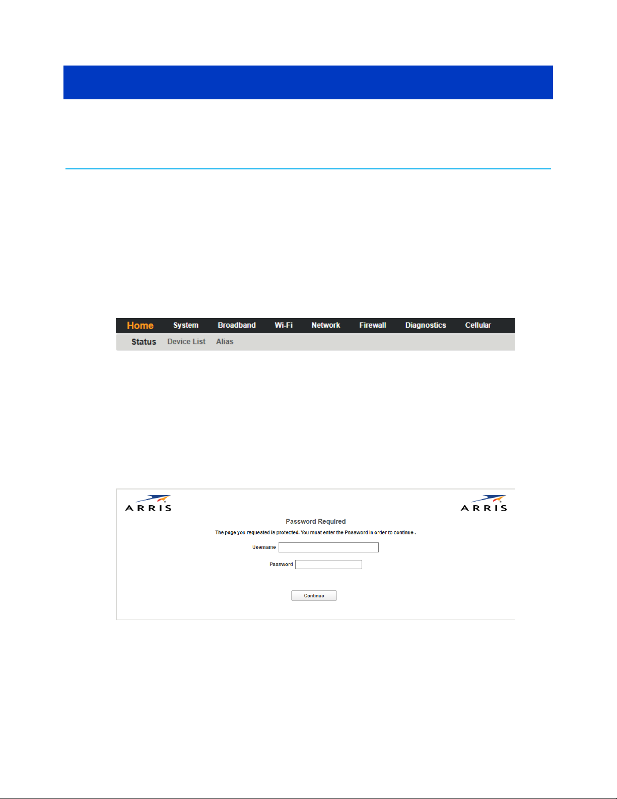
Login
Allows you to access the Gateway configuration pages.
Browse to the Gateway (http://myrouter) and login when you are prompted. Some web
pages are password protected. Protected pages require additional logins (Access Code)
because configuration changes or changes to a Gateway's state are possible on protected
pages. To go further, the Access Code must be typed in the Access Code text box. The
Default Access code is printed on a label on the bottom of the Gateway.
Click Continue after typing the Default Access Code or the Access Code that was configured
into the Gateway to access the password protected page.
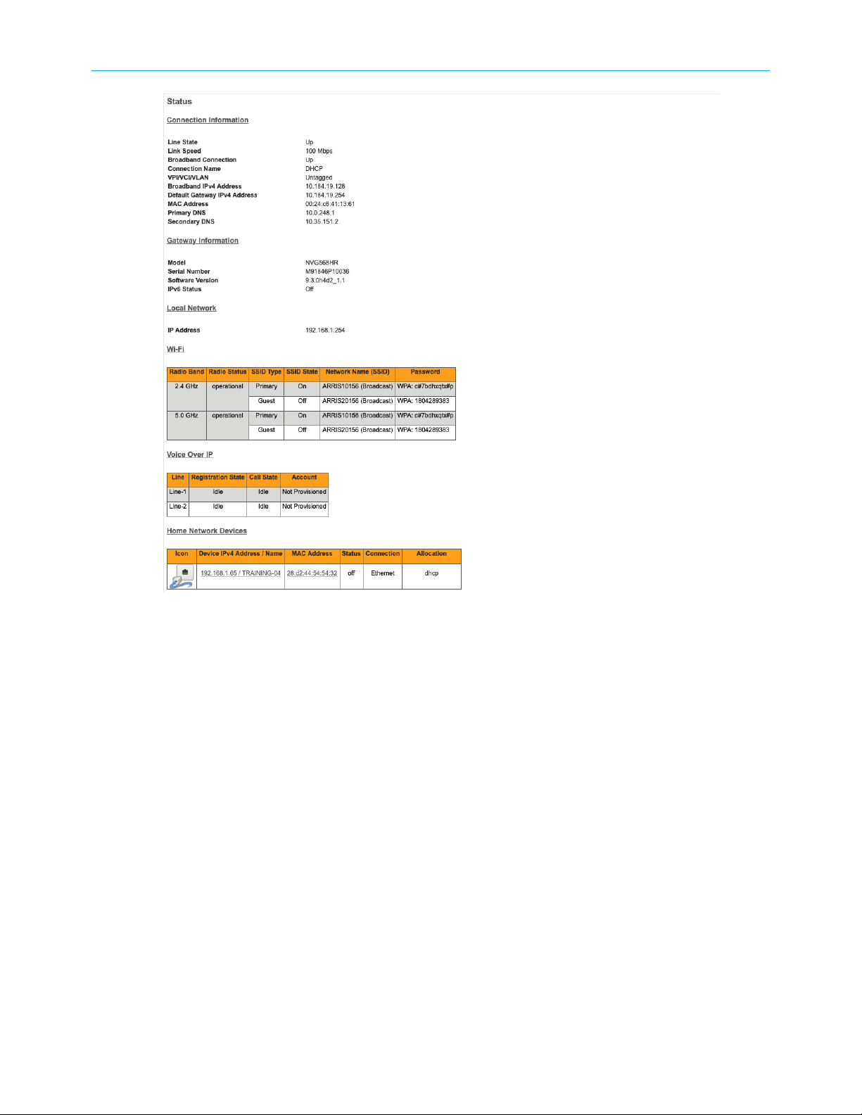
Home
Shows general network configuration and status.
Select the Home tab to open the Status page.
NVG558 4G-LTE Gateway User Manual STANDARD Revision x.1 25
Page 26
Chapter 4: Tab and link elements defined
Connection Information
■
Line State: The status of the physical layer, up or down.
■
Link Speed: The data rate of the physical broadband connection.
■
Broadband Connection: The current state, Up (active) or Down (not active), of the
broadband connection path to the Internet.
■
Connection Name: The type of connection; one of DHCP, Static, or PPPoE.
■
VPI/VCI/VLAN: VPI, VCI or VLAN when applicable.
■
Broadband IPv4 Address: The public IP address of your gateway, whether dynamically or
statically assigned.
■
Default Gateway IPv4 Address: Your ISP’s gateway router IP address.
■
MAC Address: Your gateway’s unique hardware address identifier.
■
Primary DNS / Secondary DNS
The IP address of the primary or backup Domain Name Server.
Gateway Information
■
Model: The Gateway model number.
■
Serial Number: The Gateway serial number.
NVG558 4G-LTE Gateway User Manual STANDARD Revision x.1 26
Page 27

Chapter 4: Tab and link elements defined
■
Software Version: The version number of the current embedded software in your
Gateway.
■
IPv6 Status: Shows if the Gateway is configured to support Internet Protocol Version 6
(IPv6) addressing in addition to IPv4.
Local Network
■
IP Address: Displays the IPv4 address of the gateway on the network.
Wi-Fi
■
Radio Band: One of 2.4 GHz or 5.0 GHz.
■
Radio Status: Your wireless radio may be operational or disabled.
■
SSID Type: Either Primary or Guest.
■
SSID State: On or off.
■
Network Name (SSID): The name or ID that is displayed to a client scan.
■
Password: The password for a Wi-Fi device to connect to the internet through the
Gateway.
Home Network Devices
■
Icon: A default icon is initially chosen by the system based on whether the client is wired
or wireless. There is an option to change the icon and give the client a new name to help
identify it when traversing the web pages.
■
IPv4 Address / Name : Client IP address or network name.
■
MAC Address: The device's unique hardware address.
■
Status: Off or On.
■
Connection: The type of network connection the client is using to access your gateway.
■
Allocation: Type of IP address assignment, for example, static or DHCP.
Depending on the particular setup of the client, some fields in the Home Network Devices
table may or may not be displayed. Click on any of the active fields to change the name and
icon of the device.
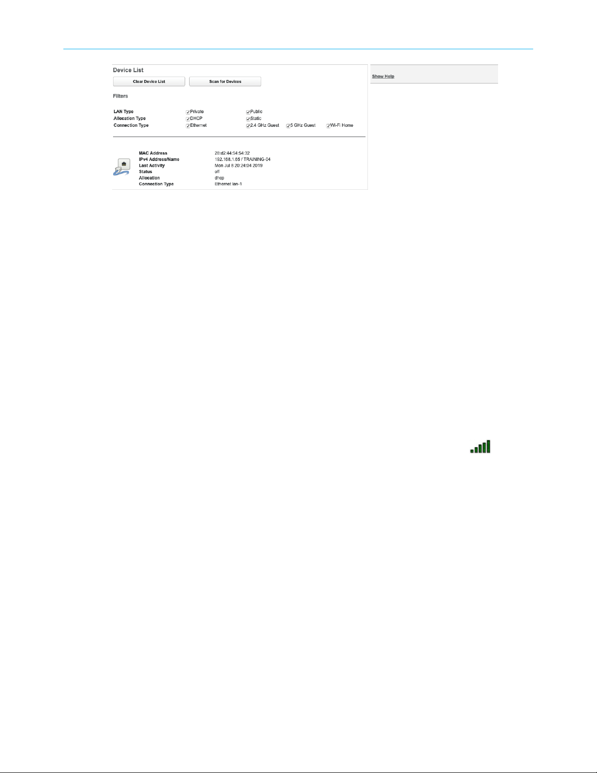
Device List
The Device List page provides access to information about devices connected to the
Gateway.
Click Device List in the Home tab to open the Device List page.
NVG558 4G-LTE Gateway User Manual STANDARD Revision x.1 27
Page 28
Chapter 4: Tab and link elements defined
Under the Filters, this page lists each connected home network device with its icon and the
following information.
■
Filters:
If there are many connected devices, it may help to filter some out by unchecking the
checkboxes in this section. Filters are:
■
LAN Type - Private and Public
■
Allocation Type - DHCP and Static
■
Connection Type - Ethernet wired and Wi-Fi
■
MAC Address: The device's unique hardware address.
■
IPv4 Address / Name : Client IP address or network name.
■
Last Activity: Date and time of last traffic passed on this device.
■
Status: Off or On.
■
Allocation: Type of IP address assignment, for example, static or DHCP.
■
Connection Type: Type of connection, for example, Ethernet or Wi-Fi.
Alias
For Wi-Fi client connections, the Device List page displays signal strength bars: . Hollow
bars indicate lower signal strength. If all bars are hollow, the device has disconnected.
Click Clear Device List to reset the Home Devices summary.
Click Scan for Devices to seek out other devices that have been connected since the last
scan. The Home Devices list is updated internally every 5 minutes. Use this button to force a
manual update immediately.
Changes the icon and the name associated with a LAN-side device, to make it easier to
identify.
Click the Alias link in the Home tab to open the Alias page.
NVG558 4G-LTE Gateway User Manual STANDARD Revision x.1 28
Page 29

Chapter 4: Tab and link elements defined
The Alias page contains a list of all devices for which an alias name/icon has been chosen.
You can display a device-specific version of this page by clicking a device in the Status or
Device List pages.
Alias Entry
■
Devices: Lists connected (or previously connected) devices by MAC address.
■
Manual Entry:If the device you want to add is not in the Devices list, enter its MAC
address.
Note: The MAC address is different for Ethernet and Wi-Fi interfaces. The
operating system's network configuration can show you the correct MAC address
for the device.
■
Alias Name: Enter the name you want to use for this device.
■
New icon: Choose the device type from the menu.
Click Add to add the alias to the list.
NVG558 4G-LTE Gateway User Manual STANDARD Revision x.1 29
Page 30

System tab
Links under the System Tab allow viewing and managing the gateway in detail.
Select the System Tab to access the System page and the System links. Some System Tab
functions mirror those found on the Home tab.
System Status
Provides general information about the Gateway.
Click the System tab to access the System page links bar and the System Status page.
Chapter 4: Tab and link elements defined
The System Status page displays the following information:
■
Manufacturer: Manufacturer’s identifier.
■
Model Number: Manufacturer’s model number.
■
Serial Number: Unique serial number of your gateway.
■
Software Version: Version number of the current embedded software in your gateway.
■
MAC Address: Unique hardware address of this gateway.
■
First Use Date: Date and time the gateway was first used.
■
Time Since Last Reboot: Elapsed time since last reboot of the gateway in
days:hours:minutes:seconds.
■
System Temperature: The internal temperature, in degrees Celsius.
■
Legal Disclaimer: Clicking the Licenses link displays a listing of software copyright
attributions.
Access Code
The Access Code page provides a way to change the password associated with the gateway
configuration.
Access to the ARRIS Embedded Software Version 9.3.0 is controlled through the Admin
account. The default Admin password for the gateway is the unique code printed on a label
on the bottom of the gateway.
NVG558 4G-LTE Gateway User Manual STANDARD Revision x.1 30
Page 31

Chapter 4: Tab and link elements defined
Restart
You can change the password to one between 8 and 20 characters long. The new password
must include characters from at least two of these categories:
■
Alphabetic (letter) characters
■
Numeric (number) characters
■
Special characters (! @ \# $ % ^ & \* and so on)
The Restart page provides a way to restart the gateway, or reset its connections.
NVG558 4G-LTE Gateway User Manual STANDARD Revision x.1 31
Page 32

Chapter 4: Tab and link elements defined
In some cases, when you make configuration changes, you may be required to restart for
the changes to take effect. If there is a problem with the service provider, restarting the
connection may be required.
■
Click the Restart Gateway button to:
● Disconnect all users
● Initialize all its interfaces
● Reload the operating system software
After clicking Restart Gateway, the following message appears.
Reset
■
Click the Restart Connection button to reinitialize the link between the gateway and
the service provider. Restarting the connection does not reload the operating system
software.
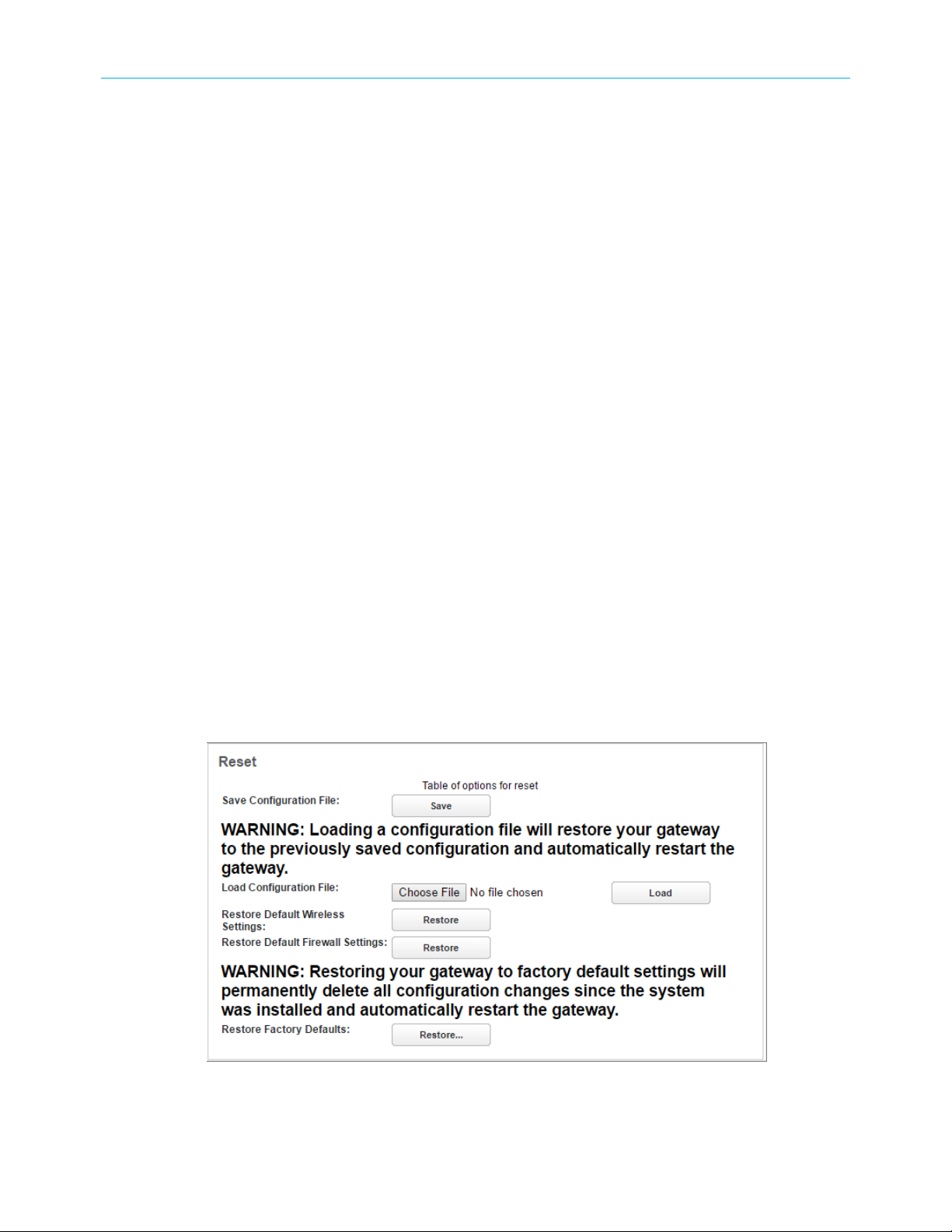
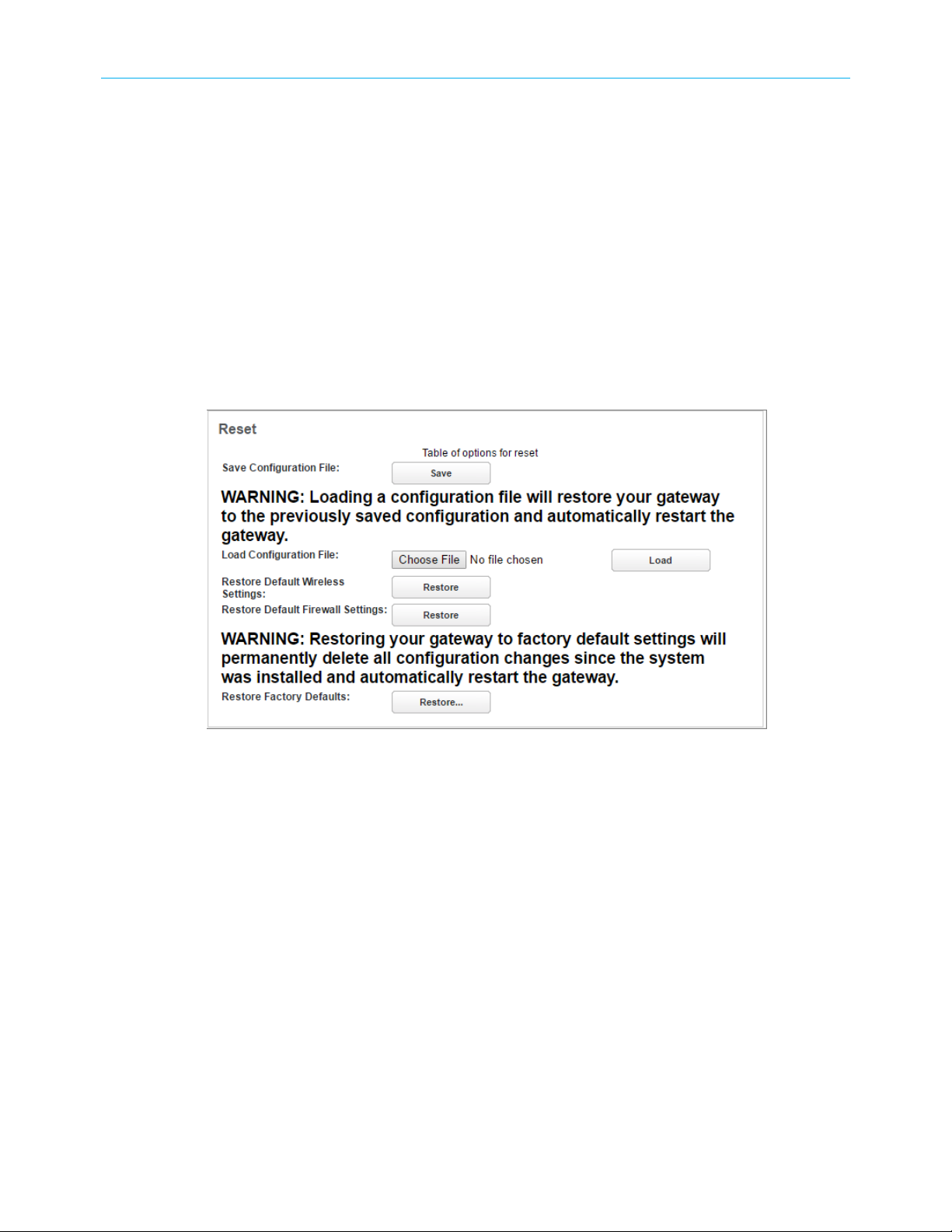
The Reset page provides access to three restore functions and a function to save a
configuration file.
NVG558 4G-LTE Gateway User Manual STANDARD Revision x.1 32
Page 33

Chapter 4: Tab and link elements defined
■
Save Configuration File
Save the current configuration to a local PC, with the default name of config.dat, to use
for restoring the settings at a later time.
■
Load Configuration File
Loading a configuration file saved from a previous software version may or may not
restore properly. On loading a configuration file the Gateway always restarts; it cannot
be cancelled.
To load a configuration file, click Choose File, find the file and then click Load.
■
Restore Default Wireless Settings
Restores only the default wireless settings of the gateway. All other user-defined
settings remain.
■
Restore Default Firewall Settings
Restores only the default firewall settings of the gateway. All other user-defined
settings remain.
■
Restore Factory Defaults
All configuration changes you have made will be deleted and settings will be returned
to factory defaults. In addition, a restart will occur, so all users connected to the
gateway or to the Internet will be disconnected.
Note: Exercise caution when performing a factory reset. A factory reset erases
all previous configuration changes made to the gateway. To bring the gateway
back to the previous configuration, begin with the Quick Start Guide associated
with the gateway.
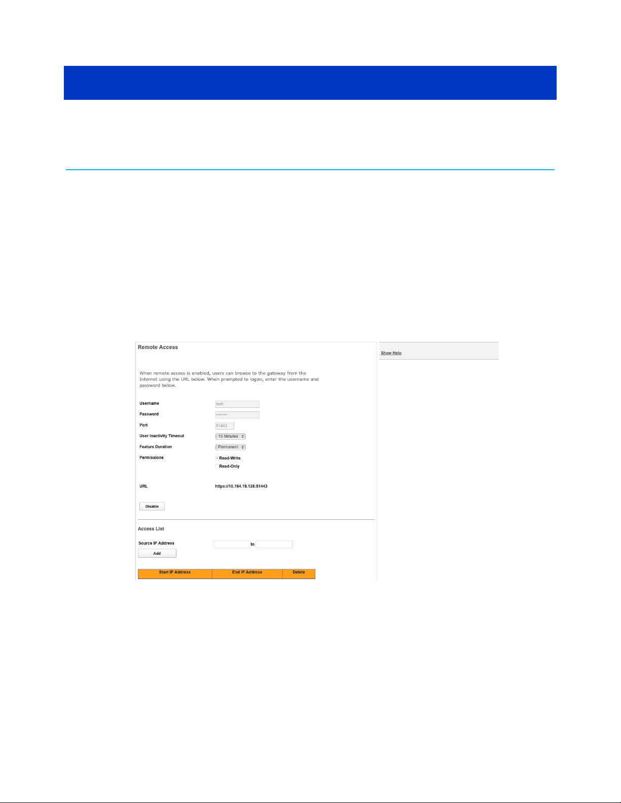
Remote Access
The Remote Access page provides access to the Gateway from the WAN. Use remote access
for advanced troubleshooting or remote configuration.
NVG558 4G-LTE Gateway User Manual STANDARD Revision x.1 33
Page 34

Chapter 4: Tab and link elements defined
Warning: Enabling remote access allows anyone who knows or can determine the
password, port ID, and URL (address) of the device to view any configuration settings
or change the operation of the device.
If remote access is not currently enabled, the Remote Access page allows configuration and
enabling.
■
Username: The user ID required to log in remotely.
■
Password: The password used for remote access.
■
Port: The port number used for remote access. Use a port in the range 49152 to 65535.
■
User Inactivity Timeout: The Gateway disconnects remote access after the specified
time expires with no activity.
■
Feature Duration: The amount of time the Gateway allows remote access.
■
Permissions: Select Read-Write or Read-Only.
■
URL: The URL required for remote access to the Gateway.
■
Enable: Click to enable remote access. When enabled, the button changes to Disable.
Access List
■
Source IP Address: A range of IP addresses. If entered, the Gateway restricts access to
devices within that address range. You can configure multiple ranges, if needed.
To restrict to a single IP address, enter the same address in both boxes.
■
Add: Click to add the configured range to the table.
The table shows configured address ranges. To delete a range, click the Delete button on
that row.
NVG558 4G-LTE Gateway User Manual STANDARD Revision x.1 34
Page 35

Misc
Chapter 4: Tab and link elements defined
The Misc page provides capability to set the Page Refresh Interval, Login Time-out value,
Local Time Zone, and Automatic Daylight Savings Time.
■
Language: Select the language used to display help and field names.
■
Page Refresh Interval: The automatic refresh interval, in seconds.
■
Login Time-out: The inactivity time-out, in minutes, after which the user will be
prompted to login to resume web page activity.
■
Firewall Redirects: When enabled, the Gateway displays a special page when blocking
access due to firewall restrictions (website or time of day).
■
Time Zone: A selection list to choose from for the time zone in which the gateway
resides.
■
Automatic Daylight Saving Time: The gateway automatically adjusts for Daylight Saving
Time. When configured in a local that does not observe Daylight Saving Time, disable
this feature.
Resources
The Resources page provides general Gateway information.
NVG558 4G-LTE Gateway User Manual STANDARD Revision x.1 35
Page 36

Chapter 4: Tab and link elements defined
■
Auto Refresh: Check this box to automatically refresh the page.
■
Model: Gateway model number.
■
Firmware: Current firmware version of the embedded operating system.
■
Current Time: Local time if:
■
The WAN is up
■
The timezone is set
■
The NTP server has been found
■
Uptime: Days, Hours, Minutes, Seconds since the gateway was restarted.
■
CPU: Displays the CPU installed in the Gateway.
■
CPU Utilization: CPU load for each core.
■
Memory: Total memory in the Gateway, and how much is used/free.
■
Flash: Total amount of Flash memory in the Gateway.
■
Sessions: The number of connections (TCP and UDP) in use, by count and by percentage
of the maximum number of sessions.
The table displays the number of sessions by connected device. Because the data is filtered,
the session count may not agree with the number of lines shown in the session table.
To update the Client Session table, click Refresh.
Broadband tab
The Broadband links provide access to information pages about the broadband connection
and to configure connection details.
Some links may differ from what is shown below, depending on model.
NVG558 4G-LTE Gateway User Manual STANDARD Revision x.1 36
Page 37

Select the Broadband tab to access the Broadband Links bar and the Broadband Status page.
Broadband Status
The Status page displays information about the Gateway WAN connection(s) to the Internet.
Select the Broadband tab to access the Broadband Links bar and the Broadband Status page.
Note: The content of this page may vary by both model and connection type. An
NVG548 page is provided as an example.
Chapter 4: Tab and link elements defined
■
Broadband Connection Source: The communications technology providing the
broadband uplink.
■
Broadband Connection: May be Up (connected) or Down (disconnected).
■
Broadband IPv4 Address: The public IP address of the gateway, whether dynamically or
statically assigned.
■
Gateway IPv4 Address: The ISP's gateway router IP address.
■
MAC Address: The gateway’s unique hardware address identifier.
■
Primary DNS: The IP address of the primary Domain Name System (DNS) server.
■
Secondary DNS: The IP address of the backup DNS server, if available.
■
MTU: Maximum transmittable unit before packets are broken into multiple packets.
■
Connection Name: The type of connection, e.g. DHCP, Static, or PPP.
NVG558 4G-LTE Gateway User Manual STANDARD Revision x.1 37
Page 38

Chapter 4: Tab and link elements defined
■
VPI/VCI/VLAN: VPI, VCI or VLAN when applicable.
■
Lease (seconds): The remaining time on the gateway's current DHCP lease.
■
Uptime (seconds): The time in seconds from the last reboot of the gateway.
IPv6
■
Status: May be Enabled or Unavailable.
■
Global Unicast IPv6 Address: The public IPv6 address of the gateway, whether
dynamically or statically assigned.
■
Border Relay IPv4 Address: The public IPv4 address of the gateway.
■
6rd Prefix: (if present) The ISP's IPv6 prefix. IPv6 RD (Rapid Deployment) uses this
technique to encapsulate IPv6 packets in IPv4.
IPv6 Statistics
■
Transmit Packets: IP packets transmitted.
■
Transmit Errors: Errors on IP packets transmitted.
■
Transmit Discards: Number of IPv6 packets dropped.
Connection Statistics
The Gateway shows the connection statistics for the current connection (Ethernet, LTE, etc.).
■
Line State (Transport): Indicates if the line is Up or Down.
■
Current Speed: (Ethernet only) The link speed.
■
Current Duplex: (Ethernet only) The Ethernet duplex state: full or half.
■
Receive Packets: IP packets received.
■
Transmit Packets: IP packets transmitted.
■
Receive Bytes: Number of bytes received on the port.
■
Transmit Bytes: Number of bytes sent out of the port.
■
Receive Unicast: Number of unicast packets received on the port.
■
Transmit Unicast: Number of unicast packets sent out from the port.
■
Receive Multicast: Number of multicast packets received on the port.
■
Transmit Multicast: Number of multicast packets sent out from the port.
■
Receive Dropped: Number of packets received on the port that were dropped.
■
Transmit Dropped: Number of packets sent out of the port that were dropped.
■
Receive Errors: Errors on IP packets received.
■
Transmit Errors: Errors on IP packets transmitted.
■
Collisions: Number of packets that had to be discarded as a result of collisions whereby
two devices tried to transmit data on the network at the same time.
Click Clear Statistics to reset the counted values to zero.
NVG558 4G-LTE Gateway User Manual STANDARD Revision x.1 38
Page 39

Broadband Settings
Displays the configured settings associated with the Gateway broadband interface.
Select the Broadband Settings link under the Broadband tab to view Broadband Settings.
■
WAN Type:
Often the system will automatically configure the WAN. If not, select the type of WAN
you are connecting from the drop-down list.
■
Line Mode:
Chapter 4: Tab and link elements defined
You may need to adjust the Line Mode for the WAN type that was selected.
Note: The Line Mode selections shown depend on the WAN Type selected.
■
Transport Mode:
You may need to adjust the Transport Mode after the WAN Type and Line Mode have
been selected.
■
VLAN ID: If the Line Mode or Transport Mode is tagged, enter the VLAN ID. Valid range: 0
to 4095.
Connection Settings
Displays the configured settings associated with the Gateway broadband connection.
Select the Connection Settings link under the Broadband tab to view the Connection
Settings.
Note: Some fields are displayed only for certain protocols.
NVG558 4G-LTE Gateway User Manual STANDARD Revision x.1 39
Page 40

Chapter 4: Tab and link elements defined
■
ISP Protocol
In most cases, the system automatically determines the ISP Protocol. Otherwise, select
the desired protocol. Options displayed on the screen vary depending on your previous
selections.
■
Protocol Detected: If ISP Protocol is Auto Select, the currently selected ISP protocol.
■
Host Name: Free text entry for the host name.
■
Domain Name: Free text entry for the domain name.
■
MTU: Choose Auto or Manual.
■
MTU size: If MTU is set to Manual, specifies the largest packet size of a frame. For
PPPoE, the maximum is 1492; otherwise, 1500.
■
DNS Type: Dynamic DNS or Static DNS. Select Static DNS to manually enter Primary and
Secondary DNS Addresses.
■
Primary DNS Address: IP address of the primary DNS server. The address used by the
gateway to lookup addresses.
■
Secondary DNS Address: Optional DNS Address if the primary server is unavailable.
Static IP-specific fields
These fields display only when ISP Protocol is Static IP.
■
Single Static IP: The ISP-assigned fixed value for the IP address.
■
Subnet Mask: The ISP-assigned fixed value for the subnet mask.
■
Gateway Address: The ISP-assigned fixed value for the default gateway.
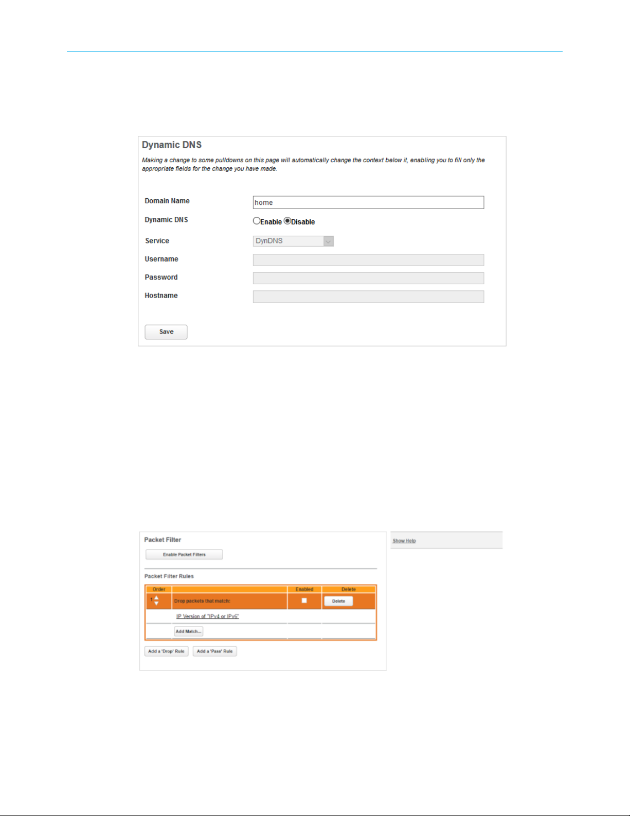
Dynamic DNS
The Dynamic DNS page allows association of variable DHCP- or PPPoE-assigned IP addresses
with a domain name you own (for example, www.examplehobbyist.com).
NVG558 4G-LTE Gateway User Manual STANDARD Revision x.1 40
Page 41

Chapter 4: Tab and link elements defined
Note: You must have an account with one of the dynamic DNS service providers
(DynDNS, ZoneEdit, etc.) listed in the Service drop-down list box.
■
■
■
■
■
■
Routing
The Routing page provides the capability to configure Routing Information Protocol (RIP)
send and receive on LAN and WAN sites in the upper panel. The lower panel allows you to
configure custom routes.
Select Routing from the Broadband tab to view the Routing page.
Domain Name: The name of your domain, such as example.com.
Dynamic DNS: Select Enable to enable Dynamic DNS.
Service: Select your Dynamic DNS provider from the drop-down menu.
Username: Your Dynamic DNS provider account.
Password: The password associated with the entered user name.
Hostname: The name of your host. This may be the same as your domain name, or
include a prefix such as www.example.com.
NVG558 4G-LTE Gateway User Manual STANDARD Revision x.1 41
Page 42

Chapter 4: Tab and link elements defined
■
LAN RIP Send: Select a version to enable Routing Information Protocol (RIP) Transmit.
■
LAN/WAN RIP Receive: Select a version to enable RIP receive.
■
LAN/WAN MD5 Key: Key used for V2-MD5.
Custom routes
■
Route Name: The custom route name.
■
Destination: The final destination IP address of the packet.
■
Netmask: Displays the Netmask information configured in the device.
■
Gateway: The device through which packets pass to reach the destination.
■
Interface: The outgoing network interface the device should use when forwarding the
packet to the next hop or final destination.
■
Metric: The metric to apply to this route. Most routes have a value of 1; use higher
numbers for slower or more congested routes.
Routing Table
The routing table of the Gateway.
NVG558 4G-LTE Gateway User Manual STANDARD Revision x.1 42
Page 43

Chapter 4: Tab and link elements defined
Wi-Fi tab
The Wi-Fi Status page provides access to configuration options and viewable information
about the gateway Wireless network.
Select the Wireless tab to access the Wi-Fi Status page and links bar.
Wi-Fi Status
The Wi-Fi Status page shows the current gateway Wi-Fi configuration details, and provides
the means to restart either wireless radio.
Click the Wi-Fi tab to open the Wi-Fi Status page.
NVG558 4G-LTE Gateway User Manual STANDARD Revision x.1 43
Page 44

Chapter 4: Tab and link elements defined
Wi-Fi Status
■
Wi-Fi Status: Status of each Wi-Fi radio: operational or disabled.
■
Wi-Fi Home: Status of the Wi-Fi home network.
■
Band: The frequency band of each Wi-Fi radio.
■
Mode: The Wi-Fi mode of operation.
■
Bandwidth: The width of each channel, in megahertz.
■
Current Radio Channel: The radio channel that the Wi-Fi network is broadcasting on.
■
Automatic Channel Selection: May be set to on or off.
■
Backhaul SSID: If a HomeAssure-enabled wireless extender is in the home network, the
Backhaul SSID carries traffic between the Gateway and the extender.
Primary SSID
If Wi-Fi Home is On, these fields provide information about the SSID.
■
Primary SSID Enabled: On if the home SSID is available on each radio.
■
SSID Availability: Indicates whether the SSID can be accessed by a wireless client, taking
into account if the radio is enabled and functional, if the SSID is enabled, if a Wireless
Schedule is enabled, if a Wireless Schedule is enabled for the SSID, and if the schedule
time is blocked/allowed.
■
Primary Network Name: This name should appear when a Wi-Fi client searches for
available networks.
NVG558 4G-LTE Gateway User Manual STANDARD Revision x.1 44
Page 45

Chapter 4: Tab and link elements defined
■
Broadcast SSID: When on, the gateway broadcasts its network name (SSID) to clients
scanning for wireless networks. When off, to connect to your wireless LAN, clients must
know the Network Name.
■
Wi-Fi Security: The security mechanism between the gateway and its clients.
■
Password: The Wi-Fi password, if security is WPA.
■
MAC Address Filtering: On indicates that gateway is inspecting MAC addresses before
connecting Wi-Fi clients.
■
Wi-Fi MAC Address: The MAC address of the Wi-Fi subsystem of this gateway.
Guest SSID
If the Guest SSID is enabled, these fields provide information about the SSID.
■
Guest SSID: Indicates which radio provides guest network access.
■
SSID Availability: Indicates whether the SSID can be accessed by a wireless client, taking
into account if the radio is enabled and functional, if the SSID is enabled, if a Wireless
Schedule is enabled, if a Wireless Schedule is enabled for the SSID, and if the schedule
time is blocked/allowed.
■
Network Name: The network name associated with the guest network.
■
Broadcast SSID: When on, the gateway broadcasts its network name (SSID) to clients
scanning for wireless networks. When off, to connect to your wireless LAN, clients must
know the Network Name.
■
Wi-Fi Security: The security mechanism between the gateway and its clients.
■
Password: The Wi-Fi password, if security is WPA.
■
MAC Address Filtering: On indicates that the gateway is inspecting MAC addresses
before connecting Wi-Fi clients.
■
Wi-Fi MAC Address: The MAC address of the Wi-Fi subsystem of this gateway.
Wi-Fi Network Statistics
■
Transmit Bytes: Number of bytes transmitted on the Wi-Fi network.
■
Receive Bytes: Number of bytes received on the Wi-Fi network.
■
Transmit Packets: Number of packets transmitted on the Wi-Fi network.
■
Receive Packets: Number of packets received on the Wi-Fi network.
■
Transmit Error Packets: Number of errors on packets transmitted on the Wi-Fi network.
■
Receive Error Packets: Number of errors on packets received on the Wi-Fi network.
■
Transmit Discard Packets: Number of packets transmitted on the Wi-Fi network that
were dropped.
■
Receive Discard Packets: Number of packets received on the Wi-Fi network that were
dropped.
Wi-Fi Client Connection Statistics
■
MAC Address: The hardware address of each client.
■
IP Address: The network address assigned to the client by this gateway.
NVG558 4G-LTE Gateway User Manual STANDARD Revision x.1 45
Page 46

■
State: Authentication state.
■
Access Point: Access point, including the band of the Wi-Fi radio and the Network Name
(SSID).
■
RSSI: Received Signal Strength Indicator value in dBm and displayed in bars, while
connected.
■
Tx/Rx Rate: The speed in Mbps that packets travel between the gateway and the Wi-Fi
client.
To restart either of the wireless radios, click the Restart Wi-Fi Radio button at the bottom of
the appropriate column. All clients using the radio will be disconnected.
The statistics counters can be reset at any time by clicking the Clear Statistics button.
Wi-Fi Home
The Wi-Fi Home screen allows you to enable and disable the ARRIS Wi-Fi Home Wi-Fi
optimization application. This feature combines your 2.4GHz and 5GHz Wi-Fi networks into
a single Wi-Fi network and promotes Wi-Fi devices to move between each band to ensure
the best coverage and bandwidth is available. The ARRIS Wi-Fi Home Wi-Fi optimization
application is enabled by default.
Chapter 4: Tab and link elements defined
■
Status: Choose Enable to display the other fields.
Note: When Status is Disable, the Wi-Fi tab shows the Primary link for
configuring basic SSID parameters.
■
Network Name (SSID): Enter the SSID name to use. The Gateway applies the SSID to
both radios.
■
WPA Version: Select the WPA version. The Gateway applies the selected value to both
radios.
■
Password: Enter the password you want to use to access Wi-Fi. The Gateway applies the
password to both radios.
After making changes, click Save for the changes to take effect.
Primary
The Primary page configures basic Wi-Fi settings on either radio.
When Wi-Fi Home (band steering) is disabled, select the Primary link.
NVG558 4G-LTE Gateway User Manual STANDARD Revision x.1 46
Page 47

Chapter 4: Tab and link elements defined
■
Radio Selection: Choose either 2.4 GHz Radio or 5.0 GHz Radio.
■
Radio state
Indicates if the Wi-Fi radio is enabled or disabled.
■
Wi-Fi Channel
Choose Automatic to have the Gateway select the best operating channel for its
environment. If a nearby wireless access point is transmitting on the same channel as
the Gateway, the networks interfere with each other, reducing throughput on both. If
you experience speed problems on your wireless LAN, test whether a particular choice
of channel improves the data transfer.
■
Network Name (SSID)
The network ID used to identify this particular wireless LAN. The default SSID for the
Gateway is Verizon-xxxx where xxxx is either 1 or 2 plus the last 4 digits of the serial
number located on the side of the gateway.
Depending on their operating system or client wireless card, users must either:
■
Select from a list of available wireless LANs that appear in a scanned list on their
client.
■
Enter this name on their clients in order to join this wireless LAN.
You can configure up to three SSIDs.
■
Isolate: Set to Enable to force all connections between devices to go through the service
provider's network, even if both devices are connected to the same wireless network.
■
Broadcast SSID
When on (the default), the Gateway broadcasts its Network Name (SSID) to clients
scanning for wireless networks. To connect to your wireless LAN, they must first choose
the Network Name.
If disabled, this mode hides the wireless network from the scanning features of
wireless client computers. Hiding the SSID prevents casual detection of the wireless
network by unwanted neighbors and passers-by. The gateway WLAN will not appear
NVG558 4G-LTE Gateway User Manual STANDARD Revision x.1 47
Page 48

Chapter 4: Tab and link elements defined
when clients scan for access points. If enabled, you must remember to enter the SSID
when adding clients to the wireless LAN.
Note: While disabling the Broadcast SSID may prevent casual discovery of the
wireless network, enabling security is the only true method of securing the
network.
■
Security
The type of wireless encryption security in use:
■
OFF-No Privacy
■
WPA-PSK
■
WPA-Default Password
See Wi-Fi security (page 54).
■
WPA Version
This field allows you to select the WPA version (WPA, WPA2, or WPA3) required for
client connections. Select WPA2 for maximum interoperability.
■
Password
The password must be at least eight characters when WPA is chosen.
Guest
After making changes, click Save for the changes to take effect.
The Guest page configures settings for a guest network.
■
Radio Selection: Choose either 2.4 GHz Radio or 5.0 GHz Radio.
■
Guest SSID Enable: Select Enable to deploy a guest network.
■
Guest Network Name: Enter the SSID you want to use for the guest network.
■
Isolate: Set to Enable to force all connections between devices to go through the service
provider's network, even if both devices are connected to the same wireless network.
NVG558 4G-LTE Gateway User Manual STANDARD Revision x.1 48
Page 49

Chapter 4: Tab and link elements defined
■
Broadcast SSID
When on (the default), the Gateway broadcasts its Network Name (SSID) to clients
scanning for wireless networks. To connect to your wireless LAN, they must first choose
the Network Name.
If disabled, this mode hides the wireless network from the scanning features of
wireless client computers. Hiding the SSID prevents casual detection of the wireless
network by unwanted neighbors and passers-by. The gateway WLAN will not appear
when clients scan for access points. If enabled, you must remember to enter the SSID
when adding clients to the wireless LAN.
Note: While disabling the Broadcast SSID may prevent casual discovery of the
wireless network, enabling security is the only true method of securing the
network.
■
Security
The type of wireless encryption security in use:
■
OFF-No Privacy
■
WPA-PSK
■
WPA-Default Password
See Wi-Fi security (page 54).
■
WPA Version
This field allows you to select the WPA version (WPA, WPA2, or WPA3) required for
client connections. Select WPA2 for maximum interoperability.
■
Password
The password must be at least eight characters when WPA is chosen.
After making changes, click Save for the changes to take effect.
Advanced
The Advanced page configures advanced settings on the Wi-Fi network.
Select the Advanced link to access the Advanced page.
NVG558 4G-LTE Gateway User Manual STANDARD Revision x.1 49
Page 50

Chapter 4: Tab and link elements defined
■
Radio Selection: Choose either 2.4 GHz Radio or 5.0 GHz Radio.
■
WMM Power Save: Enables WMM power save management. This can extend battery
life for mobile devices by putting their radios into a low-power mode when not actively
communicating.
■
Power Level: Select the lowest power level (where 100% indicates maximum power) to
cover your home or office. This is more important in high-density dwellings, to reduce
interference with neighboring networks.
■
Mode: The Wi-Fi mode of operation.
■
Channel Width
The default (20 MHz) is compatible with all devices. Set to 20/40 MHz if most devices
support 40 MHz channels. Note that any 20 MHz-only device on the network forces all
devices back to 20 MHz bandwidth.
■
RTS Threshold: Sets the packet size limit. When the threshold is passed, the ready to
send/clear to send (RTS/CTS) function is invoked. The default setting is 2347 bytes. The
allowable setting range is from 1 to 2347 bytes.
■
Beacon Interval: Sets the time interval between beacon transmissions, in milliseconds.
The Gateway uses these transmissions to synchronize the wireless network and its client
devices. For best compatibility, use the default 100ms setting. Valid range: 20 to 1024ms.
■
DTIM Interval: Sets the DTIM (Delivery Traffic Indication Message) Interval. The DTIM
Interval informs the wireless client devices of the next available window for listening to
broadcast and multicast messages. When the Gateway sends a DTIM beacon, the client
devices hear the beacon and then listen for the messages. For best compatibility, leave
the DTIM Interval at the default 1ms setting. Valid range: 1 to 255 ms.
■
Fragmentation Threshold: Sets the fragmentation threshold. This threshold should be
set to equal the maximum Ethernet frame size allowable on the link, including overhead.
Setting a lower threshold can lower data throughput, since large frames could be
fragmented and/or collisions could occur. The default setting is 2346. Valid range: 256 to
2346 bytes.
■
WPA Group Rekey Interval
The interval, in minutes, between exchanging new secret keys with each connected
device. Secret keys are used to authenticate the devices to the protected network.
After making changes, click Save for the changes to take effect.
MAC Filtering
Use MAC Filtering to restrict access to your network.
Select the MAC filtering link under the Wi-Fi tab to open the MAC Filtering page.
NVG558 4G-LTE Gateway User Manual STANDARD Revision x.1 50
Page 51

Chapter 4: Tab and link elements defined
Tools
■
MAC Filtering: Set each of the SSIDs as needed:
■
Disable: Turns off MAC filtering for this network.
■
Allow: Enables access only to the clients in the list (whitelisting). This provides high
security, but requires you to add new devices to the list.
■
Deny: Denies access to the clients in the list (blacklisting).
■
Select Device
Devices in this list are already connected to a network. Check the boxes corresponding
to the networks you want to list this device in.
■
Manually Add MAC Address: If you know the MAC address of a device you want to
list, and it does not show up in the Select Device drop-down, enter it here. The format
is nn:nn:nn:nn:nn:nn, where nn Is two hexadecimal digits (0-9, a-f). Check the boxes
corresponding to the networks you want to list this device in.
■
Add: Click this button to add the selected device to the list.
The table at the bottom of this page shows the listed devices, and their status (allowed or
denied) on each network. Click the Delete button next to a device to remove it from the list.
After making changes, click Save for the changes to take effect.
The Tools page scans the Wi-Fi bands and shows the activity on each channel.
NVG558 4G-LTE Gateway User Manual STANDARD Revision x.1 51
Page 52

Chapter 4: Tab and link elements defined
When first entering the Wi-Fi Tools screen, it displays a channel change history for both
radios.
To scan for channel quality and nearby access points, click Analyze Wireless. The scan
covers a frequency range within the 2.4 GHz or 5.0 GHz band. Channel selection depends on
government regulated radio frequencies that vary from region to region. Channel selection
can have a significant impact on performance, depending on other wireless activity close to
this gateway.
Important: This scan disconnects any wireless client devices while in progress.
After the analysis completes, the Gateway displays graphs, showing a score for each channel
tested on each radio. The score accounts for noise, interference, and traffic from other
access points. The Gateway also displays a table showing other detected access points. The
following is an example.
Access Points
Radio Channel BandwidthRSSI Network Name (SSID)/MAC MAC
2.4 GHz 1 20 MHz -72 dBm AUR_EC0086 00:06:0D:5E:DD:F5
2.4 GHz 1 20 MHz -52 dBm Motorola 00:26:82:3A:92:D7
2.4 GHz 3 20 MHz -48 dBm island-0B3B20 D4:68:4D:4B:3B:23
5 GHz 36 20 MHz -64 dBm DG6800S-F702E-5G 78:96:84:DB:B2:3F
5 GHz 48 80 MHz -34 dBm Hidden:20:F1:9E:C8:45:F3 20:F1:9E:C8:45:F3
5 GHz 48 80 MHz -34 dBm bhARRIS0245 22:F1:9E:C9:43:D7
NVG558 4G-LTE Gateway User Manual STANDARD Revision x.1 52
Page 53

Radio Channel BandwidthRSSI Network Name (SSID)/MAC MAC
5 GHz 48 40 MHz -59 dBm telenet-AEC6E 5C:35:3B:4A:EC:74
5 GHz 48 40 MHz -56 dBm telenet-AEE5F 5C:35:3B:4A:EE:65
WPS (Wi-Fi Protected Setup)
WPS is a simple way to add and securely configure new clients on the WLAN.
Chapter 4: Tab and link elements defined
Wi-Fi Protected Setup (WPS) is not a security protocol. By default, Privacy is set to Wi-Fi
Protected Access (WPA-PSK) with a 12-character security key. WPS allows you to securely
share the exact security configuration with a new client that you are adding to the WLAN,
without needing to look up and type this security key.
Clients can be added by implementing any of the WPS setups on this page. Not all wireless
devices support WPS. Refer to their documentation.
■
Radio Selection:
Provides selection for either the 2.4 Ghz or the 5.0 Ghz frequencies.
Note: The Gateway allows only one radio to have WPS enabled at a time. The
device defaults to ON for the 5 GHz radio.
■
Wi-Fi Protected Setup:
May be either Enable or Disable. To activate WPS features below, select Enable and
click Apply.
■
Generate PIN:
Click Generate PIN; a unique 8 digit PIN is generated.
■
WPS PIN:
To add a new client:
■
Choose the desired radio (2.4 GHz or 5 GHz) from the Radio Selection pull-down.
NVG558 4G-LTE Gateway User Manual STANDARD Revision x.1 53
Page 54

■
Schedule
Use the Schedule page to make a Wi-Fi network unavailable at certain times of day.
Chapter 4: Tab and link elements defined
■
Enter the new client's PIN (a string of numbers) in the WPS PIN field.
■
Click Submit to Primary SSID.
■
Follow any instructions that came with the wireless client.
WPS Virtual Pushbutton:
To add a new client:
■
Choose the desired radio (2.4 GHz or 5 GHz) from the Radio Selection pull-down.
■
Click the WPS Pushbutton to Primary SSID.
■
Follow any instructions that came with the wireless client.
By default, wireless access is blocked from midnight to 5 a.m. You must ensure your Gateway
WAN is up, timezone is set properly, and the Gateway has found the NTP server for this
feature to work.
Wi-Fi security
By default, wireless security is set to WPA with a pre-defined WPA-Default key.
Other options are available from the Security drop-down menu that is included in each page
under the Wi-Fi tab:
■
WPA-PSK: Allows you to enter your own key, the most secure option for the wireless
network. The key can be between eight and 63 characters, but for the best security it
should be at least 20 characters. If you select WPA-PSK as the privacy setting, the WPA
Version drop-down menu allows you to select the WPA version(s) that will be required
for client connections. Choices are:
● WPA-2, for maximum security
● WPA/WPA-2 or WPA-2/WPA3, for maximum interoperability
NVG558 4G-LTE Gateway User Manual STANDARD Revision x.1 54
Page 55

All clients must support the version(s) selected in order to successfully connect.
Important: Ensure that the Wi-Fi client adapter supports this option. Not all WiFi clients support WPA-PSK.
■
OFF-No Privacy: Disables privacy on the network, allowing any wireless users to connect
to the wireless LAN. Select this option if you are using alternative security measures such
as VPN tunnels, or if the network is for public use.
Network tab
Links in the Network tab allow configuration of LAN-side services.
Select the Network tab to access the Network Status page and the links bar.
Network Status
Chapter 4: Tab and link elements defined
Displays status and statistics for LAN-side interfaces.
Select the Network tab to view the status of the Network elements.
NVG558 4G-LTE Gateway User Manual STANDARD Revision x.1 55
Page 56

Chapter 4: Tab and link elements defined
■
Gateway IPv4 Address: The Gateway’s own IP address on the network.
■
DHCPv4 Netmask: Gateway’s own netmask on the network.
■
DNS Proxy: The Gateway can provide DNS service for LAN clients.
■
DHCP Server: If enabled, the Gateway is providing DHCP services to LAN clients.
■
DHCPv4 Start Address: Starting IP address of the DHCP range served by the Gateway.
■
DHCPv4 End Address: Ending IP address of the DHCP range served by the Gateway.
■
DHCP Leases Available: Number of IP addresses of the DHCP range available to be
served by the Gateway.
■
DHCP Leases Allocated: Number of IP addresses of the DHCP range currently being
served by the Gateway.
■
Lease Time: The amount of time a LAN client keeps an IP address before needing to
renew the lease.
■
DHCP Primary Pool: Number of IP addresses of the DHCP range currently being served
by the Gateway.
■
Auto Reservation: Indicates if IP addresses become reserved as they are handed out by
the DHCP server.
■
Secondary Subnet: Shows Enabled if a Public Subnet or Cascaded Router is configured.
NVG558 4G-LTE Gateway User Manual STANDARD Revision x.1 56
Page 57

Chapter 4: Tab and link elements defined
■
Public Subnet: Whether a second subnet to distribute public addresses to DHCP clients
has been configured on the Home Network Subnets & DHCP page.
■
Cascaded Router Status: Whether a routing gateway behind this gateway has been
specified on the Home Network Subnets & DHCP page.
■
IP Passthrough Status: Whether an IP passthrough has been configured on the Firewall
IP Passthrough page.
Interfaces
Interface Status Active Devices Inactive Devices
Ethernet, Wi-Fi
2.4GHz, or Wi-Fi 5GHz.
State of the specified
interface (Ethernet,
Wi-Fi, etc.).
■
Enabled
■
Disabled
Number of local
devices currently using
the interface.
Number of local
devices connected but
not currently using the
interface.
IPv6
■
Status: May be Enabled or Unavailable
■
Global IPv6 Address: The public IPv6 address of the gateway, whether dynamically or
statically assigned.
■
Link-local IPv6 Address: The private IPv6 address of the gateway, whether dynamically
or statically assigned.
■
Router Advertisement Prefix: The IPv6 prefix to include in router advertisements.
■
IPv6 Delegated LAN Prefix: The IPv6 network address prefix that identifies the
Gateway's network.
IPv4 Statistics/IPv6 Statistics
■
Transmit Packets: IP packets transmitted.
■
Transmit Errors: Errors on IP packets transmitted.
■
Transmit Discards: IP packets dropped.
■
Receive Packets: IP packets received.
■
Receive Errors: Errors on IP packets received.
■
Receive Discards: IP packets dropped.
LAN Ethernet Statistics
■
State: May be Up or Down.
■
Transmit Speed: Maximum speed of which the port is capable.
■
Transmit Packets: Number of packets sent out from the port.
■
Transmit Bytes: Number of bytes sent out from the port.
■
Transmit Dropped: Number of packets sent out from the port that were dropped.
■
Transmit Errors: Number of errors on packets sent out from the port.
NVG558 4G-LTE Gateway User Manual STANDARD Revision x.1 57
Page 58

■
Receive Packets: Number of packets received on the port.
■
Receive Bytes: Number of bytes received on the port.
■
Receive Unicast: Number of unicast packets received on the port.
■
Receive Multicast: Number of multicast packets received on the port.
■
Receive Dropped: Number of packets received on the port that were dropped.
■
Receive Errors: Number of errors on packets received on the port.
To clear the current LAN statistics information, click Clear Statistics.
Configure (Ethernet LAN)
The Network Configure link provides access to Ethernet LAN configuration elements.
Chapter 4: Tab and link elements defined
For each Ethernet Port, 1 through 4, valid selections are:
■
Ethernet:
● Auto (the default self-sensing rate)
● 10M full- or half-duplex
● 100M full- or half-duplex
● or 1G full- or half-duplex
■
MDI-X:
● Auto (the default self-sensing crossover setting)
● Off
● On
After making changes, click Save for the changes to take effect.
Subnets & DHCP
Configures Internet protocol details for the home network.
Click the Network Subnets & DHCP link, and apply configuration details in the active text
boxes.
NVG558 4G-LTE Gateway User Manual STANDARD Revision x.1 58
Page 59

Chapter 4: Tab and link elements defined
The server configuration determines the functionality of the DHCP settings. This
functionality enables the Gateway to assign the LAN computer(s) a "private" IP address
and other parameters that allow network communication. This feature simplifies network
administration because the Gateway maintains a list of IP address assignments. Additional
computers can be added to the LAN without the need to configure an IP address. This is the
default mode.
Reference the subsections that follow for field definitions.
Private LAN Subnet
■
Gateway IPv4 Address: The IP address of the device as seen from the LAN.
■
Subnet Mask: The subnet portion of the IP addresses on the private LAN subnet.
DNS Proxy
■
DNS Proxy Enable: When enabled, the gateway will be the DNS server to LAN clients.
DHCP Server
The Start and End addresses must be in the same subnet as the Gateway IPv4 Address value.
■
DHCP Server Enable: Specifies if the Gateway hands out leases to LAN-side clients.
■
DHCPv4 Start Address: First IP address in the range being served to LAN clients by the
Gateway DHCP server.
■
DHCPv4 End Address: Last IP address in the range being served to LAN clients by the
Gateway DHCP server.
NVG558 4G-LTE Gateway User Manual STANDARD Revision x.1 59
Page 60

Chapter 4: Tab and link elements defined
■
DHCP Lease: Specifies the default length for DHCP leases issued by the router. Enter
lease time in dd:hh:mm:ss (days/hours/minutes/seconds) format.
■
Option 66: The IP address or the hostname of a single TFTP server.
■
Custom Option: Custom options may be added one at a time. The option may be 1-254.
Public Subnet
■
Public Subnet Mode: To enable a second subnet to distribute public addresses to DHCP
clients, choose Public Subnet from the drop-down menu; IP addresses assigned to LAN
clients will then be public addresses.
■
Public IPv4 Address: The IP address of the gateway, as seen from the WAN.
■
Public Subnet Mask: Public subnet mask.
■
DHCPv4 Start Address: First IP address in the range being served from a DHCP public
pool.
■
DHCPv4 End Address: Last IP address in the range being served from a DHCP public pool.
■
Primary DHCP Pool: Enable a public subnet to have two DHCP pools from which to
provide IP addresses to clients. If you choose the Primary DHCP Pool to be public, the
Public Pool is used until there are no more addresses available, then the Private Pool
addresses are given. If you select Private, the Private Pool addresses are given out first.
Cascaded Router
■
Cascaded Router Enable: Select On from the drop-down menu when there is another
router behind this Gateway.
■
Cascaded Router Address: After selecting On from the drop-down menu, enter the IP
address of the router behind this gateway in the LAN private IP subnet range.
■
Network Address: After selecting On from the drop-down menu, enter the Network
Address that defines the range of IP addresses available to clients of the router behind
this gateway.
■
Subnet Mask: After selecting On from the drop-down menu, enter the Subnet Mask for
the network address that defines the range of IP addresses available to clients of the
router behind this gateway.
To apply configuration changes, click Save, and if prompted, restart the gateway.
DHCP Reservation
Use DHCP Reservation to implement auto or manual DHCP lease reservation.
NVG558 4G-LTE Gateway User Manual STANDARD Revision x.1 60
Page 61

Chapter 4: Tab and link elements defined
■
DHCP Auto Reservation: Automatically reserves the address of a client when it makes its
first attempt to get a DHCP lease.
■
Manual DHCP Reservation: Manually saves an IP address of a particular client in
the event the client is not yet connected, if Auto Reservation is disabled, or if Auto
Reservation has reached its limit.
DHCP Leases
Provides lease information for DHCP clients in tabular format.
■
DHCP Server: Indicates if the DHCP service is enabled.
■
LAN: Indicates if the primary DHCP pool is public or private.
■
DHCP Clients: Provides lease information for DHCP clients in tabular format.
ARP Table
Provides access to the Gateway ARP table.
NVG558 4G-LTE Gateway User Manual STANDARD Revision x.1 61
Page 62

UPnP
Chapter 4: Tab and link elements defined
■
Click Refresh to refresh the information on the ARP table.
■
Click Clear ARP Table to clear information from the ARP table. Note that entries may be
repopulated before the display refreshes.
The UPnP screen provides the status of the UPnP and a table of UPnP clients on the gateway.
■
Advertisement Period: The period, in seconds, the Gateway broadcasts UPnP
information. A shorter advertisement period ensures control points have current device
status, at the expense of additional network traffic.
■
Advertisement Time to Live (TTL): The number of hops before the advertisement
disappears. (A hop is the number of steps allowed to propagate for each UPnP
advertisement.)
■
IGD/NAT-T: Internet Gateway Device Protocol for Network Address Translation (NAT).
Must always be enabled.
Firewall tab
Links on the Firewall tab provide access to security configuration pages on the gateway.
NVG558 4G-LTE Gateway User Manual STANDARD Revision x.1 62
Page 63

Firewall Status
Displays the current state of the system firewall elements. Those elements turned on are
labeled Enabled
Select the Firewall tab to open the Firewall Status page.
Level
Sets the level of firewall protection to Off, Low or High.
The Firewall Level link provides access to this page of the Firewall. If IPv6 is disabled, the
lower section of the page is not shown.
Chapter 4: Tab and link elements defined
■
Off: All inbound and outbound traffic to the WAN is allowed.
■
Low: All outbound traffic and service exports such as pinholes, are supported.
Unsolicited inbound traffic from the WAN will be dropped.
■
High:
Pinholes and other service exports are disabled.
The following set of network services are allowed to be initiated by LAN-side devices:
■
TELNET
■
FTP
■
HTTP
■
HTTPS
■
SMTP
■
DNS
NVG558 4G-LTE Gateway User Manual STANDARD Revision x.1 63
Page 64

■
POP3
■
IMAP
■
NTP
All other traffic will be dropped.
Traffic initiated from WAN-side devices, except for remote administration, will be
dropped.
After making changes, click Save for the changes to take effect.
Port Triggering
A trigger port offers temporary pinholes that are opened in response to particular outbound
traffic, under the assumption that an application creates an outbound session X, and
requires an inbound session Y to be forwarded through the NAT/Firewall into the LAN.
The Port Triggering link provides access to the Port Triggering page of the Firewall.
Chapter 4: Tab and link elements defined
■
Application Name
The name of the triggering rule you are creating that is not provided in the Select
Application drop-down list.
■
Trigger Protocol
Applicable protocols are: TCP/UDP, TCP, and UDP.
■
Trigger Port Range
Enter the lowest port number in the range in the left box and the highest number in
the right box. (Apply the same port number in both boxes if not a range.)
■
Open Protocol
Applicable protocols are: TCP/UDP, TCP, and UDP.
■
Open Port Range
The port or range of port on the selected protocol which will receive the pin-holed
traffic.
Click Add after making any changes to the Port Triggering configuration.
NVG558 4G-LTE Gateway User Manual STANDARD Revision x.1 64
Page 65

Port Forwarding
Port Forwarding allows certain services to be forwarded directly from the Internet
to a particular device. Some Internet applications, e.g. online games, file exchange,
communications programs and servers, require port forwarding.
The Firewall Port Forwarding link provides access to the Port Forwarding page.
Hosted applications created by other applications cannot be modified on this page. You can
create custom services if the application or service is not listed.
Chapter 4: Tab and link elements defined
Predefined games and software are available from the Service drop-down menu. See List of
supported games and software (page 66). If you do not see the game or software in the
list of pre-configured services, create a new custom service.
See Device List (page 27) for information on the device list accessed in Port Forwarding.
■
To configure a custom service, click Custom Services (page 66).
■
To view the protocols and port ranges used by a supported game or service, select the
service name and click Service Details.
■
To remove a software service or game from the Hosted Applications list, choose the
software service or game and click Delete.
The Service Details include:
■
Service: The name of the custom service or application.
■
Protocol: Applicable protocols are: TCP/UDP, TCP, and UDP.
NVG558 4G-LTE Gateway User Manual STANDARD Revision x.1 65
Page 66

■
Global Port Range: The range of ports this application uses. Both boxes should contain
the same port number if not a range.
Custom Services
Configures a custom port triggering service.
Chapter 4: Tab and link elements defined
■
Edit:Click to edit an existing service. This populates the Service Entry fields with the
current entry values.
Note: A custom service must be inactive before it can be edited.
■
Delete: Click to remove the service.
Service Entry
■
Service Name: A unique identifier for the custom service.
■
Global Port Range: Range of ports on which incoming traffic will be received.
■
Base Host Port: The port number at the start of the port range the Gateway should use
when forwarding traffic of the specified type(s) to the internal IP address.
■
Protocol: Protocol type of Internet traffic:
■
TCP
■
UDP
■
Both
■
Add: Click to save the changes.
Each time a custom service is added, the entry is added to the list of service names in
the Service List. After defining a custom service, it becomes available in the Service
menu on the Port Forwarding page as one of the selectable services.
■
Return to Port Forwarding: Click to return to the Port Forwarding page.
List of supported games and software
AIM Talk Act of War - Direct Action Age of Empires II
NVG558 4G-LTE Gateway User Manual STANDARD Revision x.1 66
Page 67

Chapter 4: Tab and link elements defined
Age of Empires, v.1.0 Age of Empires: The Rise of
Age of Mythology
Rome, v.1.0
Age of Wonders America's Army Apache
Asheron's Call Azureus Baldur's Gate I and II
Battlefield 1942 Battlefield Communicator Battlefield Vietnam
BitTornado BitTorrent Black and White
Blazing Angels Online Brothers in Arms - Earned in
Brothers in Arms Online
Blood
Buddy Phone CART Precision Racing, v 1.0 Calista IP Phone
Call of Duty Citrix Metaframe/ICA Client Close Combat III: The Russian
Front, v 1.0
Close Combat for Windows 1.0 Close Combat: A Bridge Too
Far, v 2.0
Combat Flight Sim: WWII
Counter Strike DNS Server
Combat Flight Sim 2: WWII
Pacific Thr, v 1.0
Europe Series, v 1.0
Dark Reign Delta Force (Client and Server) Delta Force 2
Delta Force Black Hawk Down Diablo II Server Dialpad
DirecTV STB 1 DirecTV STB 2 DirecTV STB 3
Doom 3 Dues Ex Dune 2000
Empire Earth Empire Earth 2 F-16, Mig 29
F-22, Lightning 3 FTP Far Cry
Fighter Ace II GNUtella Grand Theft Auto 2
Multiplayer
H.323 compliant (Netmeeting,
HTTP HTTPS
CUSeeME)
Half Life Half Life 2 Steam Half Life 2 Steam Server
Half Life Steam Half Life Steam Server Halo
Hellbender for Windows, v 1.0 Heretic II Hexen II
Hotline Server ICQ 2001b ICQ Old
IMAP Client IMAP Client v.3 IPSec IKE
Internet Phone Jedi Knight II: Jedi Outcast Kali
KazaA Lime Wire Links LS 2000
Lord of the Rings Online MSN Game Zone MSN Game Zone DX
MSN Messenger Mech Warrior 3 MechWarrior 4: Vengeance
Medal of Honor Allied Assault Microsoft Flight Simulator
Microsoft Flight Simulator 98
2000
NVG558 4G-LTE Gateway User Manual STANDARD Revision x.1 67
Page 68

Chapter 4: Tab and link elements defined
Microsoft Golf 1998 Edition, v
1.0
Midtown Madness, v 1.0 Monster Truck Madness 2, v
Motocross Madness 2, v 2.0 Motocross Madness, v 1.0 NNTP
Need for Speed 3, Hot Pursuit Need for Speed, Porsche Net2Phone
Operation FlashPoint Outlaws POP-3
PPTP PlayStation Network Quake 2
Quake 3 Quake 4 Rainbow Six
RealAudio Return to Castle Wolfenstein Roger Wilco
Rogue Spear SMTP SNMP
SSH server ShoutCast Server SlingBox
Soldier of Fortune StarCraft StarLancer, v 1.0
Starfleet Command TFTP TeamSpeak
Telnet Tiberian Sun: Command and
Total Annihilation Ultima Online Unreal Tournament Server
Microsoft Golf 1999 Edition Microsoft Golf 2001 Edition
Monster Truck Madness, v 1.0
2.0
Timbuktu
Conquer
Urban Assault, v 1.0 VNC, Virtual Network
Warrock Westwood Online, Command
Wolfenstein Enemy Territory World of Warcraft X-Lite
XBox 360 Media Center XBox Live 360 Yahoo Messenger Chat
Yahoo Messenger Phone ZNES eDonkey
eMule eMule Plus iTunes
mIRC Auth-IdentD mIRC Chat mIRC DCC - IRC DCC
pcAnywhere (incoming)
Packet Filter
Packet filtering can improve network security by blocking unwanted traffic from passing
through the Gateway.
Select the Packet Filter link under the Firewall tab.
Warlords Battlecry
Computing
Win2000 Terminal Server
and Conquer
NVG558 4G-LTE Gateway User Manual STANDARD Revision x.1 68
Page 69

Chapter 4: Tab and link elements defined
■
Enable Packet Filters: Click to enable packet filtering. When enabled, this button
becomes Disable Packet Filters.
■
Add Match: Click to enter the source or destination IP address the filter matches. Before
using this button, use one of the following two.
■
Add a 'Drop' Rule: Click to add a rule that drops packets matching the filter.
■
Add a 'Pass' Rule: Click to add a rule that forwards packets matching the filter.
Public Subnet Hosts
Creates a subnet with a public IP address range on your LAN. Use only as instructed by your
network provider.
Click the Firewall Public Subnet Hosts link.
Click the link to proceed to the Home Network > Subnets & DHCP (page 58) page.
IP Passthrough
Allows a single PC on the LAN to use the public IP address of the Gateway.
This page also provides port address translation (PAT) or (NAPT – Network Address and
Port Translation) through the same public IP address for all other hosts on the private LAN
subnet.
NVG558 4G-LTE Gateway User Manual STANDARD Revision x.1 69
Page 70

■
Allocation Mode: The passthrough mode; one of:
■
Off: disables passthrough.
■
Passthrough: assigns the Gateway's public IP address to a single LAN-side client.
■
Default Server: forwards externally-initiated traffic to a specific LAN-side client. Use
this if you have a publically-available server, or have a network application that uses
arbitrary port numbers (for example, certain online games).
Chapter 4: Tab and link elements defined
The available fields in this page change, depending on the selected allocation mode.
Select Passthrough from the Allocation Mode pull-down menu, to assign and reuse the
public WAN IP on a LAN computer. Use DHCP for addressing the designated passthrough PC.
The acquired or configured WAN address is passed to DHCP, which will dynamically configure
a single-servable-address subnet. This dynamic subnet configuration is based on the local
and remote WAN address and subnet mask.
IP Passthrough mode
The following fields are available in IP Passthrough mode.
■
Passthrough Mode: The method used to assign the WAN IP address to the selected LAN
client:
■
DHCPS-dynamic: the Gateway assigns its WAN IP address to the first LAN client that
requests a DHCP lease. It may be helpful, after the gateway has obtained a WAN
IP address, to cycle the desired LAN client's interface or reboot it. On disabling this
feature, you should reboot the LAN client.
■
DHCPS-fixed: the Gateway assigns its WAN IP address to a specific LAN client. It
may be helpful, after the gateway has obtained a WAN IP address, to cycle the LAN
client's interface or reboot it. On disabling this feature, you should reboot the LAN
client.
■
Manual: a LAN client must be manually configured with the gateway's assigned
WAN IP address and gateway information.
■
Passthrough Fixed MAC Address: When Passthrough Mode is DHCPS-fixed, this is the
MAC of the selected LAN client.
NVG558 4G-LTE Gateway User Manual STANDARD Revision x.1 70
Page 71

Chapter 4: Tab and link elements defined
■
Passthrough DHCP Lease: When Passthrough Mode is DHCPS, this is the duration of the
lease that will be handed out by the gateway to the LAN client.
Default Server mode
The following fields are available in Default Server mode. Other fields are greyed out,
indicating that they do not apply.
■
Default Server Internal Address: The IP address of the LAN-side device to receive
unexpected or unknown traffic.
Choose the device from the list. If the device is not in the list (for example, it is
currently offline), enter its MAC address in the Manual Entry field.
DoS Protection
The Gateway includes default settings to block the most common types of DoS attacks. For
special requirements or circumstances, a variety of additional blocking characteristics are
offered.
Choose the Firewall DoS Protection link.
NVG558 4G-LTE Gateway User Manual STANDARD Revision x.1 71
Page 72

Chapter 4: Tab and link elements defined
In most cases, you should accept the default settings.
■
Drop packets with invalid source or destination IP address: Drops packets with invalid
source or destination IP address(es).
■
Protect against port scan: Detects and drops port scans.
■
Drop packets with unknown ether types: Drops packets with unknown ether types.
■
Drop packets with invalid TCP flags: Drops packets with invalid TCP flag settings (NULL,
FIN, Xmas, etc.).
■
Drop incoming ICMP Echo requests to LAN: Drops all ICMP (Ping) echo requests from
LAN-side devices.
■
Drop incoming ICMP Echo requests to device LAN Address: Drops all echo requests
coming from the Internet to LAN-side addresses of the Gateway.
■
Drop incoming ICMP Echo requests to device WAN Address: Drops all echo requests
coming from the Internet to WAN-side addresses of the Gateway, except anycast
addresses.
■
Flood Limit: Detects and drops packet flooding attacks.
■
Flood rate limit: Specifies the number of packets per second before dropping the
remainder.
■
Flood burst limit: Specifies the number of packets in a single burst before dropping the
remainder.
■
Flood limit ICMP enable: Detects and drops ICMP traffic packet flooding attempts.
■
Flood limit UDP enable: Detects and drops UDP traffic packet flooding attempts.
■
Flood limit UDP Pass multicast: Excludes UDP multicast traffic. On by default.
■
Flood limit TCP enable: Excludes TCP traffic. Off by default.
NVG558 4G-LTE Gateway User Manual STANDARD Revision x.1 72
Page 73

■
Flood limit TCP SYN-cookie: Drops TCP SYN cookies flooding attempts.
After making changes, click Save for the changes to take effect.
Static NAT
The Static NAT mapping feature allows for a 1–to–1 mapping between a public WAN IP
address and an internal private Local Host IP address.
Click the Firewall Static NAT link.
Chapter 4: Tab and link elements defined
UPnP
■
Status: The state of each Static NAT entry (usually Enabled).
■
Public IP Address:A public IP address, assigned by your service provider. This should not
be the WAN IP address of the Gateway.
Note: Assigning an arbitrary public IP address will not work.
■
Local Host: IP address of the LAN-side host.
■
Bypass Firewall: When enabled, unsolicited traffic bypasses any firewall rules.
■
Allow Inbound: When enabled, the Gateway forwards unsolicited traffic destined for the
public IP address to the local host.
After making changes, click Save for the changes to take effect.
Universal Plug and Play (UPnP) allows discovery UPnP-enabled devices in Microsoft
environments. Leave these settings unchanged unless instructed by support or your service
provider.
NVG558 4G-LTE Gateway User Manual STANDARD Revision x.1 73
Page 74

■
UPnP: Choose Enable to enable UPnP.
■
Advertisement Period: The period, in seconds, the Gateway broadcasts UPnP
information. A shorter advertisement period ensures control points have current device
status, at the expense of additional network traffic.
■
Advertisement Time to Live (TTL): The number of hops before the advertisement
disappears. (A hop is the number of steps allowed to propagate for each UPnP
advertisement.)
■
IGD/NAT-T: Internet Gateway Device Protocol for Network Address Translation (NAT).
Must always be enabled.
Access Control
Use the Access Control screen to block access to particular websites.
Chapter 4: Tab and link elements defined
NVG558 4G-LTE Gateway User Manual STANDARD Revision x.1 74
Page 75

Chapter 4: Tab and link elements defined
Website Blocking
■
Website URL: Enter the URL of a website you want to block, then click Add Website.
The table shows all listed websites. Click Delete next to any website to remove it from
the list.
Time of Day Profiles
You can create profiles, blocks of time when website blocking is active. Individual devices
can be assigned to different profiles.
Each row in the table displays one profile. Use the Edit button to edit that profile.
■
Profile Name: Enter the name of a new profile and click Add new profile.
■
Multiple Days: Choose Every Day, Weekdays, or Weekends.
■
Days of the week: Check or uncheck days as needed to set up your profile.
■
Access Begins at: Choose Enabled All Day, Blocked All Day, or a time of day.
■
Access Ends at: Choose a time of day later than the beginning time.
If you want to block access (for example) from 9 p.m. to 7 a.m., you need to create two
blocks of time: 9 p.m. to midnight, and 12:01 a.m. to 7 a.m.
When finished, click Add to Profile.
Blocking
Blocks selected services from Gateway clients.
■
■
■
Enable Service Blocking: When enabled, the services in the list are blocked from LANside clients. The button name changes to Disable Service Blocking.
Select Service From List: Select services from the pull-down list to be blocked. A custom
service can be blocked by creating a name and port.
Trusted IP: Manually enter the LAN-side IP address of clients to be trusted and not have
services blocked.
NVG558 4G-LTE Gateway User Manual STANDARD Revision x.1 75
Page 76

ALG
Chapter 4: Tab and link elements defined
Application Level Gateway (ALG) supports address and port translation for certain protocols
such as FTP, TFTP, SIP, etc.
■
FTP: When enabled, provides support for File Transfer Protocol.
■
H.323: When enabled, provides audio-visual communications support.
■
TFTP: When Trivial File Transfer Protocol is enabled, it allows get/put of a file from/to a
remote host.
■
PPTP: When Point-to-Point Tunneling is enabled, it supports virtual private networking.
■
IPSec: This feature helps ESP (IPsec encryption) work properly when using NAT. It can
sometimes cause problems for non-NATed hosts (such as devices on the Public LAN).
■
SIP: This feature understands the SIP protocol used by the specific applications and does
a protocol packet-inspection of traffic through it. A NAT router with a built-in SIP ALG
can re-write information within the SIP messages (SIP headers and SDP body) making
signaling and audio traffic between the client behind NAT and the SIP endpoint possible.
Diagnostics tab
Links on the Diagnostics tab provide the ability to run diagnostics, test Internet access, and
examine various information stored in logs.
Troubleshoot
Use the features on the Troubleshoot page to examine the elements and functions on the
Gateway.
NVG558 4G-LTE Gateway User Manual STANDARD Revision x.1 76
Page 77

Chapter 4: Tab and link elements defined
Note: Not all Gateway models have all the interfaces listed.
■
Run Full Diagnostics: Click to run tests on each physical interface.
Click the Details buttons for each interface to see detailed results of the tests. The
troubleshooting details retrieved depend on the router configuration and network
type.
Each test generates one of the following result codes:
Pass The test was successful.
Fail The test was unsuccessful.
Skipped The test was skipped because a test on
which it depended failed.
Pending The test timed out without producing a
result. Try running the test again.
Warning The test was unsuccessful. The service
provider equipment your Gateway connects
to may not support this test.
Test Internet Access
This test checks connectivity between the Gateway and an external IP address.
■
Address: The IP address or name of an external host system.
NVG558 4G-LTE Gateway User Manual STANDARD Revision x.1 77
Page 78

Chapter 4: Tab and link elements defined
■
Preferred Protocol: Select IPv4 or IPv6 as appropriate.
■
Ping: Sends ICMP (Ping) packets to the remote host.
■
Traceroute: Lists the route that packets take to the remote host, showing response times
for each hop.
■
NSlookup: Performs a name server lookup on the remote host.
■
Progress Window: Shows the results of a Ping, Traceroute, or NSlookup test.
Example:
This graphic is an example of the Troubleshooting details on the Ethernet Details page.
Logs
Displays saved information about the Gateway operational status.
Select the Logs link under the Diagnostics tab.
NVG558 4G-LTE Gateway User Manual STANDARD Revision x.1 78
Page 79

Chapter 4: Tab and link elements defined
■
Select Log: The logs you want to display: System and Firewall.
■
Display Level: The lowest severity level you want to display. Lower levels such as Notice
or Info provide a great deal of detailed information.
■
Clear Log: Click to erase all log entries.
■
Save to File:Click to download a copy of the logs to your computer as a text file.
NAT Table
The NAT Table page displays the network address translation sessions that are NAT mappings
used by the gateway.
Note: Some browsers, such as Internet Explorer for Windows, require specifying
the Gateway device's LAN address as a Trusted Site in Internet Options: Security.
This is necessary to allow the download of the log text file to the PC.
NVG558 4G-LTE Gateway User Manual STANDARD Revision x.1 79
Page 80

Tech Support Info
Chapter 4: Tab and link elements defined
Collects system information that can be used by technical support to debug certain issues.
Click Collect Tech Support Info to begin gathering information. When the Gateway finished,
the screen refreshes and displays another button:
Click Save Tech Support Info to File to download the information to your computer. Do not
change the name unless instructed by technical support.
NVG558 4G-LTE Gateway User Manual STANDARD Revision x.1 80
Page 81

Cellular tab
Links available on the Celluar tab provide access to configuration options and viewable
information about the cellular network.
Select the Celluar tab to access Cellular links bar.
Cellular Statistics
Displays the statistics, status, and current parameter settings of the Gateway cellular
connection.
Select the Cellular Statistics link under the Cellular tab to view the Cellular Statistics.
Chapter 4: Tab and link elements defined
NVG558 4G-LTE Gateway User Manual STANDARD Revision x.1 81
Page 82

Chapter 4: Tab and link elements defined
The Cellular Statistics page displays the following information:
Module
■
Model:
Indicates the Cellular modem model number.
■
Version: Indicates the version of the Cellular module.
■
Manufacturer: Indicates the cellular modem manufacturer.
■
Vendor: Indicates cellular module Vendor.
■
IMEI: International Mobile Equipment Identity.
■
IMSI: International Mobile Subscriber Identity.
Status
■
Cellular Connection: TIndicates the current state of the cellular data connection, up or
down.
■
RSSI: Received Signal Strength Indication.
■
Frequency Band: TIndicates the current frequency band of the cellular module.
■
MCC: Mobile Country Code.
■
MNC: Mobile Network code.
■
PCI: Physical Cell ID.
■
Cell ID: Indicates the Cell Identifier.
■
ICCID:
Integrated circuit card identifier - it is a unique number identifying the SIM card.
■
MDN: Mobile Directory Number.
■
CPIN: Indicates the SIM readiness. "READY" indicates that it's ready for operation.
■
COPS: Current network operator.
■
RSRP: Reference Signal Received Power.
■
RSRQ: Reference Signal Received Quality.
■
TX_Powe: Indicates the transmission power.
■
EARFCN : Indicates the E-UTRA Absolute Radio Frequency Channel Number.
■
DL Bandwidth: Indicates the Downlink Bandwidth.
■
UL Bandwidth: Indicates the Uplink Bandwidth.
■
SINR: Signal-to-Noise ratio in decibels.
■
Registration Status : Indicates the Registration status.
Cellular Settings
Displays the configured settings associated with the Gateway cellular connection.
Select the Cellular Settings link under the Cellular tab to view the Cellular Settings.
NVG558 4G-LTE Gateway User Manual STANDARD Revision x.1 82
Page 83

APN Management
Use the APN Management screen to view and configure the Gateway's APN settings.
Chapter 4: Tab and link elements defined
Select the APN Management link under the Cellular tab to view the APN Management
screen.
Note: Users are unable to make changes to PDP Type.
NVG558 4G-LTE Gateway User Manual STANDARD Revision x.1 83
Page 84

Troubleshooting
This chapter provides information about resolving issues with the gateway connection using
the broadband redirect messages, as well as general troubleshooting processes.
Connection issues
Use the information in this section to identify and resolve common connection issues.
No Wireless light
Symptom: The Wireless light, on the front panel, is off.
Cause: The Wi-Fi interface is disabled.
Solution:
Chapter 5
1. On the Settings tab, click LAN, and then click Wi-Fi.
2. For Wi-Fi Interface, select Enable.
3. Click Save.
The Internet is not accessible but the user interface of the gateway is accessible
Symptom: No devices can connect to remote hosts, but can connect to LAN servers and the
Gateway interface.
Cause: Broadband settings are incorrect.
Solution:
1. On the Settings tab, click Broadband.
2. On the Status page, check the connectivity status of the broadband link.
3. Restart the Gateway (if needed) to refresh the broadband connection.
LAN Issues
Use the information in this section to identify and resolve common local network issues.
NVG558 4G-LTE Gateway User Manual STANDARD Revision x.1 84
Page 85

IP address conflict
Symptom: One or more devices on the LAN display "address conflict" messages.
Cause: A device's settings are misconfigured.
Solution:
1. Open the network settings on the device.
2. Check the IP address configuration.
If the device should have a... Then...
static IP address Make sure the assigned address is outside the
dynamic IP address Make sure the device is configured to request an IP
3. If the device is using DHCP, force it to renew its lease.
There is usually a button available in the device settings called Renew Lease, or
something similar. Click this button to force the device to request a new IP address. If
there is no obvious control, save the settings and restart the device.
Chapter 5: Troubleshooting
Gateway's DHCP pool (the range of addresses it
assigns).
address using DHCP.
Cause: Gateway DHCP settings are misconfigured, allowing it to assign addresses that should
be static.
Solution:
1. On the Settings tab, click LAN, and then click DHCP.
2. Change the DHCP pool (IP address range) so that the static address is not part of the
range.
A wireless device is not locating the gateway
Symptom: The Gateway is on, but devices do not find the Gateway in the Wi-Fi settings.
Note: If Wi-Fi Home Wi-Fi optimization is enabled, it will need to be disabled before
you make make any Wi-Fi configuration changes.
Cause: SSID broadcast is disabled.
Solution:
1. On the Settings tab, click LAN, and then click Wi-Fi.
2. For SSID Broadcast, select Enable.
Cause: Wi-Fi is disabled.
Solution:
1. On the Settings tab, click LAN, and then click Wi-Fi.
2. For Wi-Fi Interface, select Enable.
3. Click Save.
NVG558 4G-LTE Gateway User Manual STANDARD Revision x.1 85
Page 86

Cannot connect to the Gateway
Symptom: Some or all devices are unable to connect to the Gateway over Wi-Fi.
Note: If Wi-Fi Home Wi-Fi optimization is enabled, it will need to be disabled before
you make any Wi-Fi configuration changes.
Cause: Wi-Fi is disabled.
Solution:
1. On the Settings tab, click LAN, and then click Wi-Fi.
2. For Wi-Fi Interface, select Enable.
3. Click Save.
Cause: Wi-Fi is enabled, but devices are not using the correct authentication type.
Solution:
1. On the Settings tab, click LAN, and then click Wi-Fi.
2. Check the gateway’s configured authentication type and compare it to the wireless
device’s configured authentication type to verify that the Gateway and the wireless
device are using the same authentication type.
Chapter 5: Troubleshooting
Cause: Older devices do not support WPA/WPA2 authentication.
Solution:
■
If possible, connect older devices using Ethernet rather than Wi-Fi.
■
Only if necessary, configure the Gateway to use WPA or no authentication.
Note: This presents security risks. If downgrading security is the only solution, set
it only when older devices need to connect.
The wireless signal strength is weak
Symptom: Client devices display low signal power, and sometimes lose the Wi-Fi connection.
Note: If Wi-Fi Home Wi-Fi optimization is enabled, it will need to be disabled before
you make any Wi-Fi configuration changes.
Cause: Wireless channel interference.
Solution:
1. Click the Wi-Fi tab, then either Primary 2.4 GHz or Primary 5 GHz.
2. Set the Wi-Fi Channel to Automatic.
3. Repeat steps 1 and 2 with the other radio, if needed.
4. Click Save.
Cause: The Gateway power is set too low.
Solution:
1. Click the Wi-Fi tab, then either Advanced 2.4 GHz or Advanced 5 GHz.
NVG558 4G-LTE Gateway User Manual STANDARD Revision x.1 86
Page 87

Chapter 5: Troubleshooting
2. Change the Power Level value to the next highest setting.
In high-density areas, set the power level to the lowest value that allows clients to
reliably connect throughout your home. This reduces interference with other nearby
networks.
3. Repeat steps 1 and 2 with the other radio, if needed.
4. Click Save.
Cause: Distance or solid objects reduce the signal.
Solution:
■
Move the device nearer to the Gateway.
Metal and concrete walls can significantly reduce the Wi-Fi signal. Drywall and wood can
also affect signal strength.
■
Move the Gateway to a location nearer to the center of your dwelling, if needed.
■
Increase the Wi-Fi power level:
a. Click the Wi-Fi tab, then either Advanced 2.4 GHz or Advanced 5 GHz.
b. Change the Power Level value to the next highest setting.
c. Click Save.
Cannot set a custom Wi-Fi password
Symptom: Attempting to change the Wi-Fi password results in an error.
Note: If Wi-Fi Home Wi-Fi optimization is enabled, it will need to be disabled before
you make any Wi-Fi configuration changes.
Cause: Using WPA/WPA2 security, the custom Wi-Fi password is not long enough.
Solution:
■
Set a password at least 8 characters long.
A length of 16 characters prevents many brute-force password guessing attacks.
The German government recommends a minimum password length of 20 characters.
Passwords may be up to 63 characters long.
Cause: Using WEP security, the password must be a fixed length.
Solution:
■
Set a WEP password as follows:
● For 64-bit WEP, the password must be exactly 5 characters long or 10 hex digits long.
● For 128-bit WEP, the password must be exactly 13 characters long or 26 hex digits
long.
Cause: Invalid characters in the passphrase.
Solution:
■
For highest compatibility, use only characters in the ASCII character set.
NVG558 4G-LTE Gateway User Manual STANDARD Revision x.1 87
Page 88

Chapter 5: Troubleshooting
Some devices may support extended character sets for WPA passphrases, but the
standards require ASCII-only.
Diagnostic issues
Use this section to identify and resolve common diagnostic issues.
Ping/Traceroute/DNS query does not respond
Symptom: On the Diagnostics Troubleshoot (page 76) page, attempting to run a Ping,
Traceroute, or NSlookup test fails.
Cause: The host name or address is incorrect.
Solution:
■
Ensure that you entered the correct host name or destination IP address in the Address
text box.
■
If you entered a host name, try replacing it with a known IP address.
Tip: Google's DNS server, 8.8.8.8, is configured to respond to Ping and
Traceroute.
Cause: No connectivity to the Internet.
Solution:
■
Proceed to The Internet is not accessible but the user interface of the gateway is
accessible (page 84).
Status lights
Use the status lights on the front of the Gateway to determine its status.
NVG558 4G-LTE Gateway User Manual STANDARD Revision x.1 88
Page 89

Front panel
Chapter 5: Troubleshooting
Rear panel
Status light Description
Power
Broadband
WAN
NVG558 4G-LTE Gateway User Manual STANDARD Revision x.1 89
Green. The power is on.
Flashing green. The Gateway is starting.
Red. The Gateway was unable to start.
Red/green. Standard reset in progress.
Flashing red. Factory reset in progress.
Blue. The Gateway is connected to the provider network.
Red. No IP address, or authentication failed.
Green Cellular WAN connection is within the configured "RSSI good" range.
Flashing green (all). WAN sync in progress.
Page 90

Status light Description
Amber WAN connection is within the configured "RSSI fair" range.
Red WAN Connection is within the configured "RSSI poor" range (consider
repositioning the NVG558).
Chapter 5: Troubleshooting
Wi-Fi
Green. Wi-Fi is enabled on either or both radios.
Slow flashing amber. WPS data or guest SSID pairing on configured radio
(2.4 GHz or 5 GHz). Button was pressed for less than 3 seconds.
Fast flashing amber. Button was pressed for more than 3 seconds. This
is an unsupported mode. Please wait until the LED stops flashing before
proceeding.
Red. Wi-Fi network failure.
Flashing red. WPS timeout or conflict (session overlap). Returns to previous
state after 30 seconds.
NVG558 4G-LTE Gateway User Manual STANDARD Revision x.1 90
Page 91

Page 92

Corporate Headquarters
CommScope · Hickory · North Carolina · 28602 · USA
www.commscope.com
 Loading...