

Page 1
Repeaters
Node AM4
4 slots
Network Elements
Manual
MF0121ACP
Page 2

DISCLAIMER:
This document has been developed by CommScope, and is intended for the use of its
customers and customer support personnel. The information in this document is subject to
change without notice. While every effort has been made to eliminate errors, CommScope
disclaims liability for any difficulties arising from the interpretation of the information contained
herein. The information contained herein does not claim to cover all details or variations in
equipment, nor to provide for every possible incident to be met in connection with installation,
operation, or maintenance. This document describes the performance of the product under the
defined operational conditions and does not cover the performance under adverse or disturbed
conditions. Should further information be desired, or should particular problems arise which
are not covered sufficiently for the purchaser’s purposes, contact CommScope.
CommScope reserves the right to change all hardware and software characteristics without
notice.
COPYRIGHT:
© Copyright 2018 CommScope Inc. All Rights Reserved.
This document is protected by copyright. No part of this document may be reproduced, stored
in a retrieval system, or transmitted, in any form or by any means, electronic, mechanical
photocopying, recording, or otherwise without the prior written permission of CommScope.
TRADEMARKS
All trademarks identified by ® or ™ are registered trademarks or trademarks, respectively, of
CommScope. Names of products mentioned herein are used for identification purposes only
and may be trademarks and / or registered trademarks of their respective companies.
Andrew Wireless Systems GmbH, 30-August-2018
Page 2 MF0121ACP_uc.docx Manual for Node AM4
Page 3

Table of Contents
TABLE OF CONTENTS
1. GENERAL 7
1.1. USED ABBREVIATIONS 7
1.2. HEALTH AND SAFETY 8
1.3. PROPERTY DAMAGE WARNINGS 8
1.4. COMPLIANCE 9
1.5. ABOUT COMMSCOPE 14
1.6. INTERNATIONAL CONTACT ADDRESSES FOR CUSTOMER SUPPORT 15
2. INTRODUCTION 17
2.1. PURPOSE 17
2.2. THE NODE AM4 REPEATER 17
2.3. QUICK START CHECKLIST 18
3. INSTALLATION 19
3.1. MECHANICAL INSTALLATION 19
3.1.1. Health and Safety for Mechanical Installation 19
3.1.2. Property Damage Warnings for Mechanical Installation 19
3.1.3. Removal of Transport Protection Cover 20
3.1.4. 19 Inch Rack Mounting of the Node AM4 20
3.1.5. RF Card Installation 22
3.2. ELECTRICAL INSTALLATION 23
3.2.1. Health and Safety for Electrical Installation 23
3.2.2. Property Damage Warnings for Electrical Installation 23
3.2.3. Grounding 24
3.2.4. Interconnection Cabling 25
3.2.5. Connection of the Antenna Cables 25
3.2.6. Cleaning Procedure for RF Cable Connectors 27
3.2.7. Antenna Cable Connector Assembly 30
3.2.8. Power Connection 31
3.2.9. Connection to the Node AM 33
3.2.9.1. Setting up the Local Connection 33
3.2.9.2. Setting up the Remote Connection 33
4. FUNCTIONAL DESCRIPTION 34
4.1. ARCHITECTURE 34
4.2. FEATURES 34
4.2.1. Digital Channel Filters 34
4.2.2. Frequency Hopping 35
4.2.3. Filter Types 35
4.2.4. Status Information 35
4.2.5. Alarm Forwarding 36
4.3. COMPONENTS 36
4.3.1. Multiband Combiner 37
4.3.2. Digital Channel Modules (DCM) / RF Cards 39
4.3.3. Dummy Card 40
4.3.4. Power Supply Unit 40
4.3.5. User Interface Board (UI1 Board) 41
MF0121ACP_uc.docx Manual for Node AM4 Page 3
Page 4

Table of Contents
4.3.5.1. External Alarms 42
4.3.5.2. Summary Alarm 44
4.3.6. User Interface 2 Board with Optional Features 46
4.3.6.1. VSWR Module Option 46
4.3.6.2. Battery Backup Option 46
4.3.6.3. Optional Modems 48
5. MAINTENANCE 52
5.1. GENERAL 52
5.2. REPLACEMENT OF COMPONENTS 52
5.2.1. Multiband Combiner 55
5.2.2. Modem / Battery 57
5.2.3. VSWR Module (Optional) 61
5.2.4. Status LED 62
5.2.5. Power Supply 63
5.2.6. RF Card Exchange / Upgrade with Additional RF Cards 66
5.2.7. Fan Unit 67
5.2.7.1. Backside Type 67
5.2.7.2. Bottom Type 68
6. ILLUSTRATIONS 71
6.1. CABINET DRAWINGS NODE AM 71
6.2. LAYOUT 71
7. SPECIFICATIONS 72
7.1. ELECTRICAL SPECIFICATIONS 72
7.1.1. RF Card Options 72
7.1.2. Bandwidths available in UL and DL per rack (single-band cards) 74
7.1.3. Bandwidths available in UL and DL per dual-band card 75
7.2. MECHANICAL SPECIFICATIONS 77
7.3. ENVIRONMENTAL AND SAFETY SPECIFICATION 77
7.4. FEATURES 77
7.5. MODEMS 78
7.5.1. HC25 / PHS8 / PLS8 / MC88 / TRM-5 78
7.5.2. Wireless Router M!DGE (Racom) 78
8. SPARE PARTS LIST 79
9. INDEX 81
10.LIST OF CHANGES 82
Page 4 MF0121ACP_uc.docx Manual for Node AM4
Page 5

Figures and Tables
FIGURES AND TABLES
figure 3-1 Grounding bolt ............................................................................................ 24
figure 3-2 Example for interconnecting cabling for a Node AM4 (combiner with three
pairs of band ports) .................................................................................. 25
figure 3-3 Front view of Node AM4 antenna connections (combiner with three pairs of
band ports) ............................................................................................... 26
figure 3-4 DC Mains connector, PIN assignment ....................................................... 31
figure 3-5 Mains connector, location .......................................................................... 31
figure 3-6 Connecting the CAT5 cable to the Node AM for the local connection....... 33
figure 4-3 Layout of a Node AM4 (combiner with three pairs of band ports), maximum
equipment ................................................................................................ 36
figure 4-4 Node AM4 3-band combiner (850-900, 1800, 2100 MHz) with three pairs of
band ports) ............................................................................................... 37
figure 4-5 Node AM4 2-band combiner (800-900 and 1800-2100 MHz) with two pairs
of band ports ............................................................................................ 38
figure 4-6 Single-band DCM, RF card, low / medium power (left) and high power with
additional DL amplifier (right) ................................................................... 39
figure 4-7 Dual band DCM, RF card (medium power) ................................................ 39
figure 4-8 Dummy card ............................................................................................... 40
figure 4-9 Power supply (DC/DC type), front and back .............................................. 40
figure 4-10 UI-board for general applications, installed.............................................. 41
figure 4-11 UI-board for general applications, top and rear view ............................... 42
figure 4-12 PIN assignment ........................................................................................ 43
figure 4-13 Schematics of external alarm clamps ...................................................... 43
figure 4-14 External cable gland ................................................................................. 44
figure 4-15 Summary alarm relay ............................................................................... 44
figure 4-16 Relay contacts, alarm condition ............................................................... 45
figure 4-17 Schematics of summary alarm clamps .................................................... 45
figure 4-18 UI2 Board kit, layout ................................................................................. 46
figure 4-19 Position of UI2 Board and BBU ................................................................ 47
figure 4-20 Modem installed, exemplary .................................................................... 48
figure 4-21 Cable from the modem to the multiband combiner, exemplary ............... 49
figure 4-22 Modem Kit HC25 / PHS8 / PLS8 Node AM, schematic wiring ................ 49
figure 4-23 Modem Kit MC88/TRM-5 Node AM, schematic wiring ............................ 50
figure 4-24 UI1 Board, position of modem RS232 connector .................................... 50
figure 4-25 SIM-card drawer ....................................................................................... 50
figure 4-26 Installation of modem RV50X................................................................... 51
figure 5-1 Installation of modem onto adapter kit ....................................................... 59
figure 5-2 VSWR module, layout ................................................................................ 61
figure 5-3 VSWR module, position of RF connectors ................................................. 61
figure 5-4 Cover of UI-card with status LED ............................................................... 62
figure 5-5 Status LED and connection cables ............................................................ 62
figure 6-1 Cabinet of a Node AM4 (fan unit backside type) ....................................... 71
figure 6-2 Layout of the Node AM4, example ............................................................. 71
MF0121ACP_uc.docx Manual for Node AM4 Page 5
Page 6

table 3-1 Description of Node AM4 antenna connectors ........................................... 26
table 3-2 AC Mains connector, PIN assignment ........................................................ 31
table 3-3 Node AM4, voltage range & external breaker ............................................. 32
table 4-1 Pin assignment of relay contacts ................................................................ 45
table 5-1 Specified torques for stainless steel screws ............................................... 53
table 5-2 Standard torques for neck-collar screws ..................................................... 53
table 5-3 Standard torques for metal cable glands .................................................... 53
table 5-4 Specified standard tolerances ..................................................................... 54
table 7-1 RF card options, EMEA, single band cards ................................................ 72
table 7-2 RF card options for USA, single band cards ............................................... 73
table 7-3 RF card options, dual band cards ............................................................... 73
table 7-4 Bandwidths available in UL and DL per rack, single-band cards ................ 74
table 7-5 Filter resources allocation (up to 5 MHz wide), example ............................ 75
table 7-6 Bandwidths available in UL and DL per dual-band card ............................. 75
table 7-7 Filter resources allocation (up to 5 MHz wide), example ............................ 76
Figures and Tables
Page 6 MF0121ACP_uc.docx Manual for Node AM4
Page 7

1. General
1. General
1.1. Used Abbreviations
3GPP 3rd Generation Partnership Project
BCCH Broadcast Control Channel
BTS Base Transceiver Station
CDMA Code Division Multiple Access
DAS Distributed Antenna System
DL Downlink
DoC Declaration of Conformity
EDGE Enhanced Data Rates for GSM Evolution
ESD Electrostatic Discharge
FRU Field Replaceable Unit
GPS Global Positioning System
GSM Global System for Mobile Communication
I2C-Bus Inter-Integrated Circuit Bus (Philips)
ID No Identification Number
ISDE Innovation, Sciences et Développement économique Canada
ISED Innovation, Science and Economic Development Canada; formerly IC / Industry Canada
LAN Local Area Network
LED Light Emitting Diode
LNA Low Noise Amplifier
MCC Mobile Country Code
MIMO Multiple Input Multiple Output
MNC Mobile Network Code
MS Mobile Station
OMC Operation and Maintenance Center
PA Power Amplifier
PCS Personal Communication System
PSU Power Supply Unit
QoS Quality of Service
RED Radio Equipment Directive
Rev Revision
RF Radio Frequency
RoHS Directive on Restriction of certain Hazardous Substances
RSSI Receive Signal Strength Indication
RX Receiver
TDMA Time Division Multiple Access
TX Transmitter
UE User Equipment
UL Uplink
UMTS Universal Mobile Telecommunication System
UPS Uninterruptable Power Supply
VSWR Voltage Standing Wave Ratio
WCDMA Wide Code Division Multiple Access
WEEE Waste Electrical and Electronic Equipment (Directive)
MF0121ACP_uc.docx Manual for Node AM4 Page 7
Page 8
1. General
1.2. Health and Safety
1. Danger: Electrical hazard. Danger of death or fatal injury from electrical current.
Obey all general and regional installation and safety regulations relating to work
on high voltage installations, as well as regulations covering correct use of
tools and personal protective equipment.
2. Danger: Electrical hazard. Danger of death or fatal injury from electrical current
inside the unit in operation. Before opening the unit, disconnect mains power.
3. Caution: High frequency radiation in operation. Risk of health hazards associated
with radiation from the unit’s inner conductor of the antenna port(s). Disconnect mains
before connecting or replacing antenna cables.
4. Caution: High frequency radiation in operation. Risk of health hazards associated
with radiation from the antenna(s) connected to the unit. Implement prevention
measures to avoid the possibility of close proximity to the antenna(s) while in
operation.
1.3. Property Damage Warnings
1. Attention: Due to power dissipation, the unit may reach a very high temperature. Do
not operate this equipment on or close to flammable materials. Use caution when
servicing the unit.
2. Attention: Only authorized and trained personnel are allowed to open the unit and
get access to the inside.
3. Notice: Although the unit is internally protected against overvoltage, it is strongly
recommended to ground (earth) the antenna cables close to the antenna connectors
of the unit for protection against atmospheric discharge. In areas with strong lightning,
it is strongly recommended to install additional lightning protection.
4. Notice: ESD precautions must be observed. Before commencing maintenance work,
use the available grounding (earthing) system to connect ESD protection measures.
5. Notice: Only suitably qualified personnel are allowed to work on this unit and only
after becoming familiar with all safety notices, installation, operation and maintenance
procedures contained in this manual.
6. Notice: Keep operating instructions within easy reach and make them available to all
users.
7. Notice: Read and obey all the warning labels attached to the unit. Make sure that all
warning labels are kept in a legible condition. Replace any missing or damaged labels.
Page 8 MF0121ACP_uc.docx Manual for Node AM4
Page 9
1. General
8. Notice: Only license holders for the respective frequency range are allowed to operate
this unit.
9. Notice: Make sure the repeater settings are correct for the intended use (refer to the
manufacturer product information) and regulatory requirements are met. Do not carry
out any modifications or fit any spare parts, which are not sold or recommended by
the manufacturer.
1.4. Compliance
1. Attention: In order to meet the Conducted Emissions requirement according to EN
61000-6-3, the following conditions must be fulfilled for units with PSU DC 680 W or
PSU DC 780 W:
a) The connecting cable to the DC voltage source must be less than 30 m long.
b) For connecting cables >30m, special material requirements must be observed,
e.g. a shielded two-wire line must be used as the input lead or a metal cable
channel/installation conduit must be used for installing the input lead.
2. Notice: For installations, which have to comply with FCC RF exposure requirements,
the antenna selection and installation must be completed in a way to ensure
compliance with those FCC requirements. Depending on the RF frequency, rated
output power, antenna gain, and the loss between the unit and antenna, the minimum
distance D to be maintained between the antenna location and human beings is
calculated according to this formula:
P
][
D
][
cm
4
mW
PD
2
]/[
cmmW
where
P (mW) is the radiated power at the antenna, i.e. the max. rated unit output power
in addition to the antenna gain minus the loss between the unit and the antenna.
PD (mW/cm²) is the allowed Power Density limit acc. to 47 CFR 1.1310 (B) for
general population / uncontrolled exposures which is
o F (MHz) / 1500 for frequencies from 300MHz to 1500MHz
o 1 for frequencies from 1500MHz to 100,000MHz
RF exposure compliance may need to be addressed at the time of licensing, as
required by the responsible FCC Bureau(s), including antenna co-location
requirements of 1.1307(b)(3).
For FCC compliance and meeting the UL requirement of 1 watt EIRP max. for the
AWS uplink band, the type of donor antenna must be selected in way not to exceed
the 1 watt EIRP. Selection of antenna type and execution of installation has to be done
in accordance to relevant FCC part and is in responsibility of the installer.
MF0121ACP_uc.docx Manual for Node AM4 Page 9
Page 10

1. General
3. Notice: For installations which have to comply with European EN50385 exposure
compliance requirements, the following Power Density limits/guidelines (mW/cm²)
according to ICNIRP are valid:
o 0.2 for frequencies from 10 MHz to 400 MHz
o F (MHz) / 2000 for frequencies from 400 MHz to 2 GHz
o 1 for frequencies from 2 GHz to 300 GHz
4. Notice: For installations which have to comply with FCC/ISED requirements:
English:
This device complies with FCC Part 15. Operation is subject to the following two conditions:
(1) this device may not cause interference, and (2) this device must accept any interference,
including interference that may cause undesired operation of the device.
This device complies with Health Canada’s Safety Code. The installer of this device should
ensure that RF radiation is not emitted in excess of the Health Canada’s requirement.
Information can be obtained at http://www.hc-sc.gc.ca/ewh-semt/pubs/radiation/radio_guidelignes_direct-eng.php.
Changes or modifications not expressly approved by the party responsible for compliance
could void the user’s authority to operate the equipment.
Antenna Stmt for ISED:
This device has been designated to operate with the antennas having a maximum gain of 9
dBi. Antennas having a gain greater than 9 dBi are prohibited for use with this device without
consent by ISED regulators. The required antenna impedance is 50 ohms.
The antenna(s) used for this transmitter must be installed to provide a separation distance of
at least 100 cm from all persons and must not be co-located or operating in conjunction with
any other antenna or transmitter. Users and installers must be provided with antenna
installation instructions and transmitter operating conditions for satisfying RF exposure
compliance.
French:
Cet appareil est conforme à FCC Partie15. Son utilisation est soumise à Les deux conditions
suivantes: (1) cet appareil ne peut pas provoquer d’interférences et (2) cet appareil doit
accepter Toute interférence, y compris les interférences qui peuvent causer un mauvais
fonctionnement du dispositif.
Cet appareil est conforme avec Santé Canada Code de sécurité 6. Le programme
d’installation de cet appareil doit s’assurer que les rayonnements RF n’est pas émis au-delà
de I’exigence de Santé Canada. Les informations peuvent être obtenues: http://www.hcsc.gc.ca/ewh-semt/pubs/radiation/radio_guide-lignes_direct-fra.php
Les changements ou modifications non expressément approuvés par la partie responsable
de la conformité pourraient annuler l’autorité de l’utilisateur à utiliser cet équipement.
Antenne Stmt pour ISDE:
Ce dispositif a été désigné pour fonctionner avec les antennes ayant un gain maximal de 9
dBi. Antennes ayant un gain plus grand que 9 dBi sont interdites pour une utilisation avec cet
appareil sans le consentement des organismes de réglementation d’ISDE. L’impédance
d’antenne requise est 50 ohms.
L’antenne (s) utilisé pour cet émetteur doit être installé pour fournir une distance de
séparation d’au moins 100 cm de toutes les personnes et ne doit pas être co-localisées ou
opérant en conjonction avec une autre antenne ou émetteur. Les utilisateurs et les
installateurs doivent être fournis avec des instructions d’installation de l’antenne et des
conditions de fonctionnement de l’émetteur pour satisfaire la conformité aux expositions RF.
Page 10 MF0121ACP_uc.docx Manual for Node AM4
Page 11

1. General
5. Notice: Installation of this equipment is in full responsibility of the installer, who has
also the responsibility, that cables and couplers are calculated into the maximum gain
of the antennas, so that this value, which is filed in the FCC Grant and can be
requested from the FCC data base, is not exceeded. The industrial boosters are
shipped only as a naked booster without any installation devices or antennas as it
needs for professional installation.
6. Notice: Corresponding local particularities and regulations must be observed. For
national deviations, please refer to the respective documents included in the manual
CD that is delivered with the unit.
7. Notice: The unit complies with Overvoltage Category II. It also complies with the surge
requirement according to EN 61000-4-5 (fine protection); however, installation of an
additional medium (via local supply connection) and/or coarse protection (external
surge protection) is recommended depending on the individual application in order to
avoid damage caused by overcurrent.
For Canada and US, components used to reduce the Overvoltage Category shall
comply with the requirements of IEC 61643-series. As an alternative, components
used to reduce the Overvoltage Category may comply with ANSI/IEEE C62.11, CSA
Certification Notice No. 516, CSA C22.2 No. 1, or UL 1449. Suitability of the
component for the application shall be determined for the intended installation.
8. Note: For a Class A digital device or peripheral:
This equipment has been tested and found to comply with the limits for a Class A
digital device, pursuant to part 15 of the FCC Rules. These limits are designed to
provide reasonable protection against harmful interference when the equipment is
operated in a commercial environment. This equipment generates, uses, and can
radiate radio frequency energy and, if not installed and used in accordance with the
instruction manual, may cause harmful interference to radio communications.
Operation of this equipment in a residential area is likely to cause harmful interference
in which case the user will be required to correct the interference at his own expense.
9. Note: For a Class B digital device or peripheral:
This equipment has been tested and found to comply with the limits for a Class B
digital device, pursuant to part 15 of the FCC Rules. These limits are designed to
provide reasonable protection against harmful interference in a residential installation.
This equipment generates, uses and can radiate radio frequency energy and, if not
installed and used in accordance with the instructions, may cause harmful interference
to radio communications. However, there is no guarantee that interference will not
occur in a particular installation. If this equipment does cause harmful interference to
radio or television reception, which can be determined by turning the equipment off
and on, the user is encouraged to try to correct the interference.
10. Note: This unit complies with European standard EN60950-1 / EN62368-1.
11. Note: This unit must be installed in areas with restricted access for skilled employees
only.
MF0121ACP_uc.docx Manual for Node AM4 Page 11
Page 12

1. General
Equipment Symbols Used / Compliance
Please observe the meanings of the following symbols used in our equipment and the
compliance warnings:
Symbol Compliance Meaning / Warning
For industrial (Part 20) signal booster:
WARNING: This is NOT a CONSUMER device. It is
designed for installation by FCC LICENSEES and
QUALIFIED INSTALLERS. You MUST have an FCC
LICENSE or express consent of an FCC Licensee to
operate this device. Unauthorized use may result in
significant forfeiture penalties, including penalties in
excess of $100,000 for each continuing violation.
For (Part 90) signal booster:
WARNING: This is NOT a CONSUMER device. It is
designed for installation by FCC LICENSEES and
QUALIFIED INSTALLERS. You MUST have an FCC
LICENSE or express consent of an FCC Licensee to
operate this device. You MUST register Class B signal
--- FCC
boosters (as defined in 47 CFR 90.219) online at
www.fcc.gov/signal-boosters/registration. Unauthorized
use may result in significant forfeiture penalties, including
penalties in excess of $100,000 for each continuing
violation.
For AWS-3:
To fulfill the FCC the UL requirement of 1 Watt EIRP max.
for the AWS uplink band, the type of donor antenna must
be selected in a way not to exceed the 1 Watt
EIRP. Antenna type selection and execution of
installation, i.e. the maximum antenna height of 10m must
not be exceeded, has to be done in accordance to the
relevant FCC part and is in responsibility of the installer.
For stationary application, an operation in the UL band
1755 to 1780 MHz is strictly prohibited by FCC.
WARNING: This is NOT a CONSUMER device. It is
designed for installation by an installer approved by an
ISED licensee. You MUST have an ISED LICENCE or the
express consent of an ISED licensee to operate this
device.
--- ISED
AVERTISSEMENT: Ce produit N’EST PAS un appareil
de CONSOMMATION. Il est conçu pour être installé par
un installateur approuvé par un titulaire de licence
d’ISDE. Pour utiliser cet appareil, vous DEVEZ détenir
une LICENCE d’ISDE ou avoir obtenu le consentement
exprès d’un titulaire de licence autorisé par ISDE.
Page 12 MF0121ACP_uc.docx Manual for Node AM4
Page 13
1. General
Symbol Compliance Meaning / Warning
To be sold exclusively to mobile operators or authorized
installers – no harmonized frequency bands, operation
CE
requires license. Intended use: EU and EFTA countries
Indicates conformity with the RED directive 2014/53/EU
and/or RoHS directive 2011/65/EU.
Indicates conformity with the RED directive 2014/53/EU
CE
and RoHS directive 2011/65/EU certified by the notified
body no. 0700.
WEEE Recycling
Country specific information about collection and recycling arrangements per the Waste
Electrical and Electronic Equipment (WEEE) Directive and implementing regulations is
available on CommScope’s website.
http://www.commscope.com/About-Us/Corporate-Responsibility-and-Sustainability/Environment/#recycling
Required Antenna Distances
Node AM/A+
Antenna gain
without
cable loss [dBi]
m inches m inches
Maximum Distance
FCC ISED
DCM AF 1727E 9 .251 9.88 .386 15.19
MF0121ACP_uc.docx Manual for Node AM4 Page 13
Page 14

1. General
1.5. About CommScope
CommScope is the foremost supplier of one-stop, end-to-end radio frequency (RF)
solutions. Part of the CommScope portfolio are complete solutions for wireless
infrastructure from top-of-the-tower base station antennas to cable systems and cabinets,
RF site solutions, signal distribution, and network optimization. For patents see www.cs-
pat.com.
CommScope has global engineering and manufacturing facilities. In addition, it maintains
field engineering offices throughout the world.
Andrew Wireless Systems GmbH based in Buchdorf/Germany, which is part of
CommScope, is a leading manufacturer of coverage equipment for mobile radio networks,
specializing in high performance, RF and optical repeaters. Our optical distributed
networks and RF repeater systems provide coverage and capacity solution for wireless
networks in both indoor installations and outdoor environments, e.g. tunnels, subways,
in-trains, airport buildings, stadiums, skyscrapers, shopping malls, hotels and conference
rooms.
Andrew Wireless Systems GmbH operates a quality management system in compliance
with the requirements of ISO 9001 and TL 9000. All equipment is manufactured using
highly reliable material. To maintain highest quality of the products, comprehensive
quality monitoring is conducted at all fabrication stages. Finished products leave the
factory only after a thorough final acceptance test, accompanied by a test certificate
guaranteeing optimal operation.
Hereby Andrew Wireless Systems declares that the radio equipment type Repeater is in
compliance with Directive 2014/53/EU.
The full text of the EU declaration is available at the following internet address:
www.commscope.com/collateral/Declarations_of_Conformity/.
According to the DoC, our “CE”-marked equipment can be used in all member
states of the European Union.
Note: Exceptions of and national deviations from this intended use may be
possible. To observe corresponding local particularities and
regulations, please refer to the respective documents (also in national
language) which are included in the manual CD delivered.
To make the most of this product, we recommend you carefully read the instructions in
this manual and commission the system only according to these instructions.
For technical assistance and support, please also contact the local office or CommScope
directly at one of the addresses listed in the following chapter.
Page 14 MF0121ACP_uc.docx Manual for Node AM4
Page 15
1. General
A
y
(
y
(
A
y
(
(
1.6. International Contact Addresses for Customer Support
Canada
CommScope Canada
Mail
Phone
Fax +1-905-878-3297 Fax +1-919-329-8950
E-mail wisupport@commscope.com E-mail wisupport@commscope.com
Mail
Phone
Fax + 55-15-2102-4001 Fax +52-55-1346-1901
E-mail wisupport@commscope.com E-mail wisupport@commscope.com
Mail
Phone +852-3106-6100 Phone +613-9300-7969
Fax +852-2751-7800 Fax +613-9357-9110
E-mail wisupport.China@commscope.com E-mail wisupport.Australia@commscope.com
CommScope Solutions International Inc.
Mail
Phone +971 4 390 09 80 Phone + 27 11-719-6000
Fax +971 4 390 86 23 Fax + 27 11-444-5393
E-mail wisupport@commscope.com E-mail wisupport@commscope.com
505 Consumers Road, Suite 803
Toronto M2J 4V8, Canada
+1-905-878-3457 (Office)
+1-416-721-5058
Cell)
A
M
Caribbean & South American Region Caribbean & Central American Region
CommScope Cabos do Brasil Ltda. CommScope Mexico S.A. de C.V.
CALA Tech Support for Distributed
Coverage & Capacity Solutions (DCCS)
products:
Rua Guaporanga, 49
Praça Seca – Rio de Janeiro – RJ
ZIP: 21320-180, Brazil
+1-815-546-7154 (Cell)
+55-15-9104-7722
China, India and Rest of Asia
Andrew International Corporation
Room 915, 9/F
Chevalier Commercial Centre
8 Wang Hoi Rd
Kowloon Ba
, Hong Kong
Office)
E
R
I
C
A
S
A
P
A
C
Middle East & North Africa
Branch)
PO Box 48 78 22
Unit 3206, Floor 32,
Jumeirah Business Center 5,
Jumeirah Lakes Towers,
Dubai, United Arab Emirates
Africa
&
Middle
East
ndrew LLC, A CommScope Compan
Mail
Phone +1-888-297-6433
Mail
Phone +52-55-1346-1900 (Office)
ndrew Corporation (Australia) Pty Ltd.
Mail
620 North Greenfield Parkway
Garner, NC 27529, U.S.A.
CALA Tech Support for Distributed
Coverage & Capacity Solutions
(DCCS) produc ts:
Av. Insurgentes Sur 688, Piso 6
Col. Del Valle, CP: 03100
Mexico Cit
Unit 1
153 Barry Road
Campbellfield
VIC 3061, Australia
Andrew Wire less Solutions Africa
Mail
United States
, Mexico
Australia & New Zealand
South Africa
PTY) LTD
11 Commerce Crescent West
Eastgate, Sandton
PO Box 786117
Sandton 2146
South Africa
MF0121ACP_uc.docx Manual for Node AM4 Page 15
Page 16

A
g
y
y
A
y
y
)
1. General
United Kingdom
Andrew Wireless Systems UK Ltd
Unit 15, Ilex Building
Mulberry Business Park
Mail
Phone +44-1189-366-792 Phone + 47 32-12-3530
Fax +44-1189-366-773 Fax + 47 32-12-3531
E-mail wisupport.uk@commscope.com E-mail wisupport@commscope.com
Mail
Phone +49-9099-69-0 Phone +33-1 82 97 04 00
Fax +49-9099-69-930 Fax +33-1 47 89 45 25
E-mail wisupport@commscope.com E-mail wisupport@commscope.com
Andrew Wireless Systems (Austria) GmbH CommScope Wireless Systems AG
Mail
Phone +43-1706-39-99-10 Phone +41-62-386-1260
Fax +43-1706-39-99-9 Fax +41-62-386-1261
E-mail wisupport.austria@commscope.com E-mail wisupport.ch@commscope.com
Mail
Phone +39-0546-697111 Phone +34-91-745-20 40
Fax +39-0546-682768 Fax +34-91-661-87 02
E-mail wisupport.italia@commscope.com E-mail wisupport.iberia@commscope.com
Mail
Phone
Fax +49 871 9659172
E-mail wisupport@commscope.com
Fishponds Road
Wokingham Berkshire
RG41 2GY, En
Andrew Wireless Systems GmbH CommScope France
Industriering 10
86675 Buchdorf
German
land
Germany France
Mail
Mail
E
U
R
O
Austria Switzerland
Weglgasse 10
2320 Wien-Schwechat
Austria
Italy Iberia Region -Spain & Portugal
CommScope Italy S.r.l., Faenza, Ital
Via Mengolina, 20
48018 Faenza (RA)
Ital
Czech Republic
CommScope Solutions Czech Republic
C-Com, spol. s r.o
U Moruší 888
53006 Pardubice, Czech Republic
+49 871 9659171 (Office)
+49 171 4001166 (Mobile
P
E
Mail
ndrew España S.A. A CommScope Compan
Mail
Scandinavia
ndrew Norway (AMNW)
P.O. Box 3066
Osloveien 10
Hoenefoss 3501
Norway
Immeuble Le Lavoisier
4, Place des Vosges
92052 Courbevoie, France
Tiergartenweg 1
CH-4710 Balsthal
Switzerland
Avda. de Europa, 4 - 2ª pta.
Parque Empresarial de la Moraleja
Alcobendas, Madrid 28108, Spain
Page 16 MF0121ACP_uc.docx Manual for Node AM4
Page 17

2. Introduction
2. Introduction
2.1. Purpose
Wireless communication systems provide a two-way information transfer (voice and data)
between a base station and multiple mobiles within a given area.
Repeaters are used to extend the transmission range if weak signal transmissions occur
within the coverage area due to indoor applications, topological conditions or distance
from the transmitter. In the downlink path, the repeater picks up the signal from a donor
antenna of an existing cell, amplifies and re-transmits it into the required dark spot. In the
uplink direction, the repeater receives signals from mobile stations present in its coverage
area and re-transmits the signals to the corresponding base station.
In the downlink (DL), the Node AM4 picks up signals coming from the base station, filters
them, amplifies them, and retransmits them to the mobile. In the uplink (UL), it picks up
signals from the mobile, filters them, amplifies them, and retransmits them to the base
station. The Node AM4 constantly monitors the quality of the signals passing through it.
2.2. The Node AM4 Repeater
Note: The denomination "Node AM4" says that this RF repeater is equipped with
slots for 4 RF cards / dummy cards.
Universal multi-band, multi-service repeater for mobile applications.
A coverage solution and a universal choice for selective transmission of interleaved
sub-bands for amplification of GSM, EDGE, TDMA, CDMA, WCDMA, HSPA, HSPA+,
and LTE signals within multiple frequency bands.
Supports up to 4 frequency bands (with single-band RF cards only) or currently up to
7-8 frequency bands (with dual-band RF cards) in a single chassis with fully integrated
multi-band combiner and modem for remote monitoring and control.
Software-based repeater platform enables on-the-fly filter changes and development
of new features and capabilities without expensive hardware upgrades.
Channel and band selective automatic gain/ power control for mobile multi-operator
and public safety applications.
Available in both medium and high power classes (for dual-band RF cards, medium
power class only) to enhance coverage in trains and ferry applications.
Automatic Frequency Allocation enable self-acting repeater reconfigurations based on
received GPS position.
Intuitive auto setup and help screens for easy system configuration, minimizing setup
time and reliance on expensive and bulky test equipment.
MF0121ACP_uc.docx Manual for Node AM4 Page 17
Page 18

Advanced statistic reports, including inbound and outbound measurement of channel
power/pilot power/RSSI to facilitate set up and verify ongoing system operation.
Remote alarming through SNMP or SMS using wireless data including GPS
positioning.
Seamless integration with Andrew’s Integrated Management and Operating System
(A.I.M.O.S.).
Rated for both indoor and outdoor use with versatile mounting option optimized for
train and ferry applications.
2. Introduction
2.3. Quick Start Checklist
Read and observe chapter 1.2.
Setting up the Node AM is quick and easy. The following step-by-step procedure
provides a quick overview for a correct setup and optimization.
a. Equipment required
Node AM
Donor antenna
Coverage antenna(s) or distributed antenna system (DAS)
Coaxial cables
Connectors (RF, mains)
Laptop or PC (Win 7, Win8, or Win 10) with Ethernet port and mains cable
Data cable (CAT5, 100 MBit).
b. Information required
Make sure the following information has been verified and is at hand:
Important on-site conditions (e. g. mains supply, available space, etc.)
Operators to be enhanced / amplified
Data of mandatory fields of Connectivity and Upload page
c. Procedure
1. Install the donor and coverage antennas (or leaky feeder).
2. Install the coaxial cables from the Node AM4 to the antennas.
3. Install the Node AM4 unit; see chapter 3.1 Mechanical Installation.
Note: Take care to ground the unit correctly as instructed in
chapter 3.2.3 Grounding.
4. Connect power and the antenna coaxial cables to the Node AM4.
5. Open the small User Interface cover plate
6. Establish a connection from the laptop or computer to the Node AM4.
7. Login to the unit and use the Technician Setup page (see Software manual)
for configuration.
Page 18 MF0121ACP_uc.docx Manual for Node AM4
Page 19

3. Installation
3. Installation
3.1. Mechanical Installation
3.1.1. Health and Safety for Mechanical Installation
Read and observe chapter 1.2.
1. Caution: Risk of injury by the considerable weight of the unit falling. Ensure there is
adequate manpower to handle the weight of the system.
2. Caution: Risk of serious personal injury by equipment falling due to improper
installation. The installer must verify that the supporting surface will safely support the
combined load of the electronic equipment and all attached hardware and
components. Only use sufficiently dimensioned screws for mounting and make sure
the mounting material is adequate for the mounting surface.
3.1.2. Property Damage Warnings for Mechanical Installation
1. Attention: Do not install the unit in a way or at a place where the specifications
outlined in the Environmental and Safety Specifications leaflet of the supplier are not
met.
2. Notice: Due to power dissipation, the unit may reach a very high temperature.
Ensure sufficient airflow for ventilation. When mounting the Node AM4 into a train, a
temperature test in maximum configuration (i.e. 4 RF cards) must essentially be
made. A minimum air flow of 50 m³/h is required where the maximum air flow of the
Node AM4 is 220 m³/h which will be reached at an environmental temperature of
around 45°C and above. We suggest to supply the repeater at the air inlet with fresh
air and to conduct warm air at the air outlet off the Node AM4 without feedback in
order to avoid a 'thermal short-circuit'.
3. Notice: It is recommended only to use the mounting hardware delivered by the
manufacturer. If any different or additional mounting material is used, ensure that the
mounting remains as safe as the mounting designed by the manufacturer. Ensure
that the static and dynamic strengths are adequate for the environmental conditions
of the site. The mounting itself must not vibrate, swing or move in any way that might
cause damage to the unit. The specifications for stationary use of the unit must not
be exceeded.
Note: Exceeding the specified load limits may cause the loss of warranty.
4. Notice: Only use sufficiently dimensioned screws for mounting and make sure the
mounting material is adequate for the mounting surface.
5. Notice: Observe that for M12 connectors the nominal torque is 1.0 N-m.
6. Notice: When connecting and mounting the cables (RF, mains, ...) ensure no water
can penetrate into the unit through these cables.
7. Notice: Do not operate the repeater without terminating the antenna connectors. The
antenna connectors may be terminated by connecting them to their respective
antennas or to a dummy load.
Unless otherwise agreed to in writing by CommScope, CommScope’s general limited
product warranty (http://www.commscope.com/Resources/Warranties/) shall be the
warranty governing the Node AMs, including the installation, maintenance, usage and
operation of the Node AMs.
MF0121ACP_uc.docx Manual for Node AM4 Page 19
Page 20
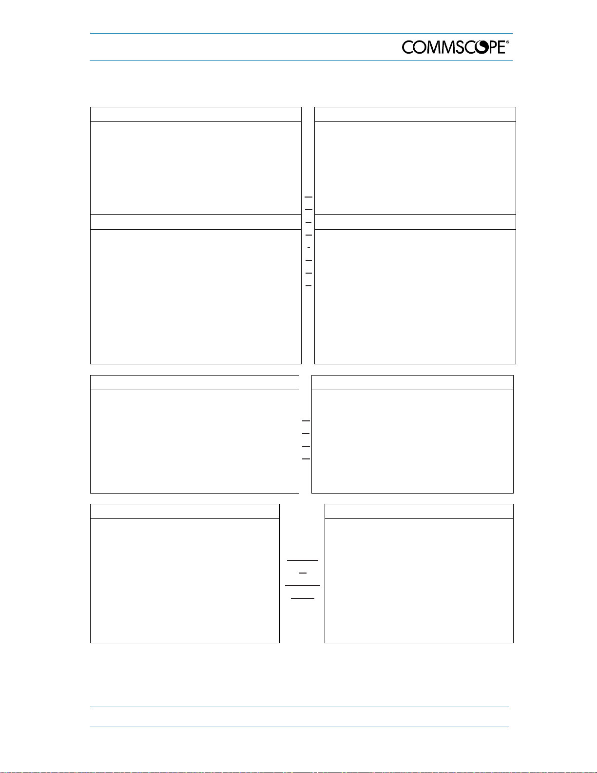
3.1.3. Removal of Transport Protection Cover
Before starting with the installation,
remove the transport protection cover
(only installed in units with bottom type
fan – see chapter 5.2.7.2). This cover is
retained by 6 screw heads at the Node’s
sides from which it can be unhinged
without having to loosen the screws.
Note: Please keep this cover
because it is required if the Node has to
be sent back, e.g. for a repair or upgrade.
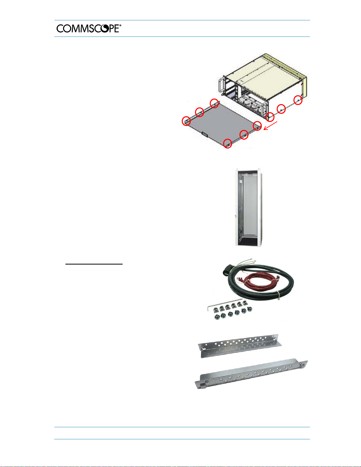
3.1.4. 19 Inch Rack Mounting of the Node AM4
1) 19’’ Rack for Node AM4 (and LMR450)
rack mounting
3. Installation
2) Mounting material:
The following components are included in
the Accessory Kit which is part of the
Node AM4 order.
1x hex screwdriver angled size 2.5
1x AC/DC cable AWG12 3M IP 67
6x cage nuts BM3861
6x M6.0x16mm raised head screws
Pozi recess
1x data cable 3 m Cat5e red
You only need four of each screws/nuts for
mounting.
The Accessory Kit does not contain the
required guide rails. Please use the guide
rails from your original supplier of the 19’’
rack.
Page 20 MF0121ACP_uc.docx Manual for Node AM4
Page 21
3. Installation
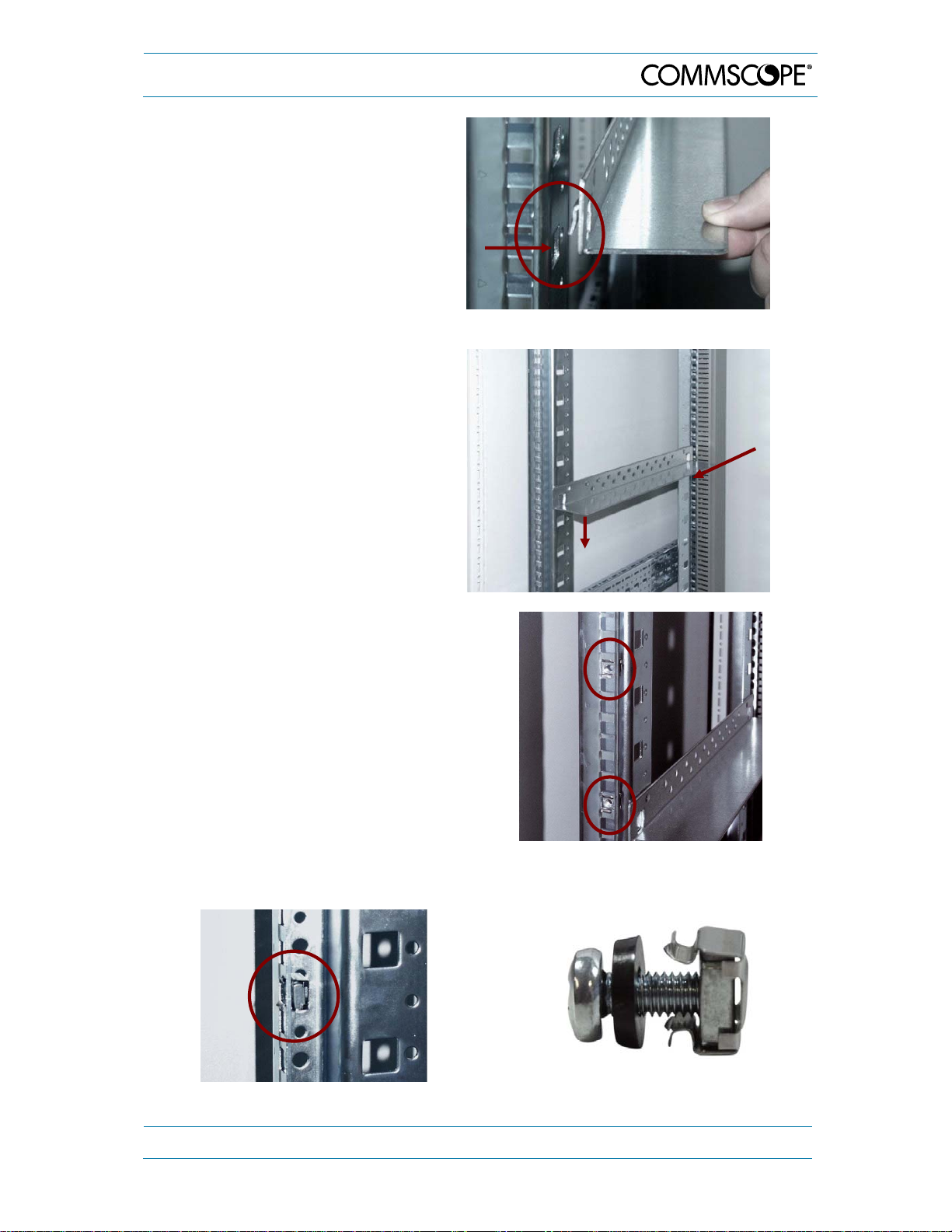
3)
Hook the guide rails into the four holes
of the vertical mounting rail of the
19’’rack.
Vertical mounting rail
4)
The free space below the guide rails
has to be at least 1 HU to ensure
sufficient air circulation. The rear side
of the Node AM4 needs a distance of
the rear side of the 19’’ rack of at least
100 mm.
100 mm
1HU
5)
Hook the cage nuts from behind in the
vertical mounting rail of the 19’’ rack.
Pay attention to the distance between
the nuts. It must fit with the holes in the
Node AM4 so it can be fastened with
screws later.
6)
Cage nut mounted (side view):
7)
Cage nut & M6.0x16 mm screw assembly:
MF0121ACP_uc.docx Manual for Node AM4 Page 21
Page 22
g
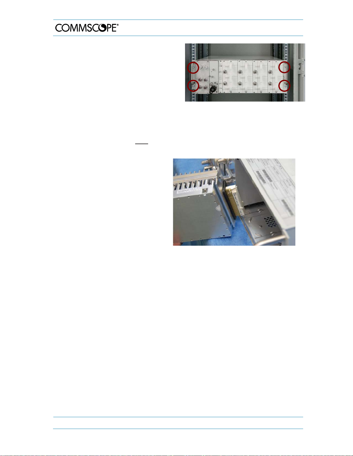
D8)
Put the Node AM4 on the rail guides and
fasten it with four M6.0x16 mm screws.
Then, install the RF cards as explained in
the next chapter.
3. Installation
3.1.5. RF Card Installation
Note 1: To ensure shock protection of the DC connectors and main board, the RF
cards are packed separately for transport. Installation of the RF cards is
recommended after the Node AM unit itself has been mounted according to
the following instruction:
Use the guide rails on top and bottom
to fit in the RF card smoothly.
Fasten* the four neck-collar screws
M3x16 mm tight to ensure
watertightness. For the specified
torque refer to the according table in
chapter 5.2 Replacement of
Components.
* First, just slightly tighten the screws
crosswise in order to avoid cant, and when
all four screws are positioned correctly,
fasten them ti
ht.
Note 2: Depending on the respective frequency range, the maximum equipment of 4
RF cards is not necessarily required but all unused slots need to be
assembled with a dummy card for sufficient airflow and provided IP class.
Note 3: It is mandatory that one RF card is installed into slot 1 as a (passive) dummy
card does not fit into slot 1. A dummy card has to be installed into slots with
no RF card to guarantee correct airflow and watertightness for the active
components. For layout please refer to figure 4 2 Exemplary layout of a Nod e
AM4, maximum equipment in chapter 4.3 Components.
Note 4: It is recommended to disconnect the Node AM4 from mains (power-supply
line) before an RF card is mounted or dismounted. In case the Node AM4 is
not allowed to be disconnected from mains, the RF card which needs to be
replaced must be disabled via software in the Technician page before
removing it. This is to avoid possible damage when inserting the new RF card
Note 5: Please observe that the RF cards must always be packed separately for
transport.
Page 22 MF0121ACP_uc.docx Manual for Node AM4
Page 23
3. Installation
3.2. Electrical Installation
3.2.1. Health and Safety for Electrical Installation
Read and observe chapter 1.2.
Danger: Electrical hazard. Danger of death or fatal injury from electrical current.
Obey all general and regional installation and safety regulations relating to
work on high voltage installations, as well as regulations covering correct use
of tools and personal protective equipment.
3.2.2. Property Damage Warnings for Electrical Installation
1. Attention: It is compulsory to ground (earth) the unit before connecting the power
supply. Grounding bolts are provided on the cabinet to connect the ground-bonding
cable.
2. Attention: If the mains connector of the unit is not easily accessible, a disconnect
device in the mains power circuit must be provided within easy reach.
3. Attention: A connection of the mains supply to a power socket requires the power
socket to be nearby the unit.
4. Attention: Before connecting or disconnecting the mains connector at the unit,
ensure that mains power supply is disconnected.
5. Attention: Make sure that an appropriate circuit breaker acting as a disconnect
device (as required by IEC/EN60950-1) and an overcurrent limiting device are
connected between mains power and the unit.
6. Attention: Incorrectly wired connections can destroy electrical and electronic
components.
7. Notice: To avoid corrosion at the connectors caused by electrochemical processes,
the material of the cable connectors must not cause a higher potential difference than
0.6 V (see electrochemical contact series).
8. Notice: Use an appropriate torque wrench for the coupling torques:
- for N-type connectors (2 N-m / 20 in lb) with 13/16 in opening,
e. g. item no. 244379 available from the CommScope e-catalog
- for 7/16 DIN-type (25 N-m / 19 ft lb) with 1 ¼ in opening,
e. g. item no. 244377 available from the CommScope e-catalog
SMA connectors have a specified torque of 60 N-cm.
Do NOT use your hands or any other tool (e.g. a pair of pliers). This might cause
damage to the connector and lead to a malfunction of the unit.
9. Notice: For unstabilized electric networks, which frequently generate spikes, the use
of a voltage limiting device is advised.
10. Notice: Observe the labels on the front panels before connecting or disconnecting
any cables.
11. Notice: Unused connectors must be closed with their protective covers to ensure
watertightness.
MF0121ACP_uc.docx Manual for Node AM4 Page 23
Page 24
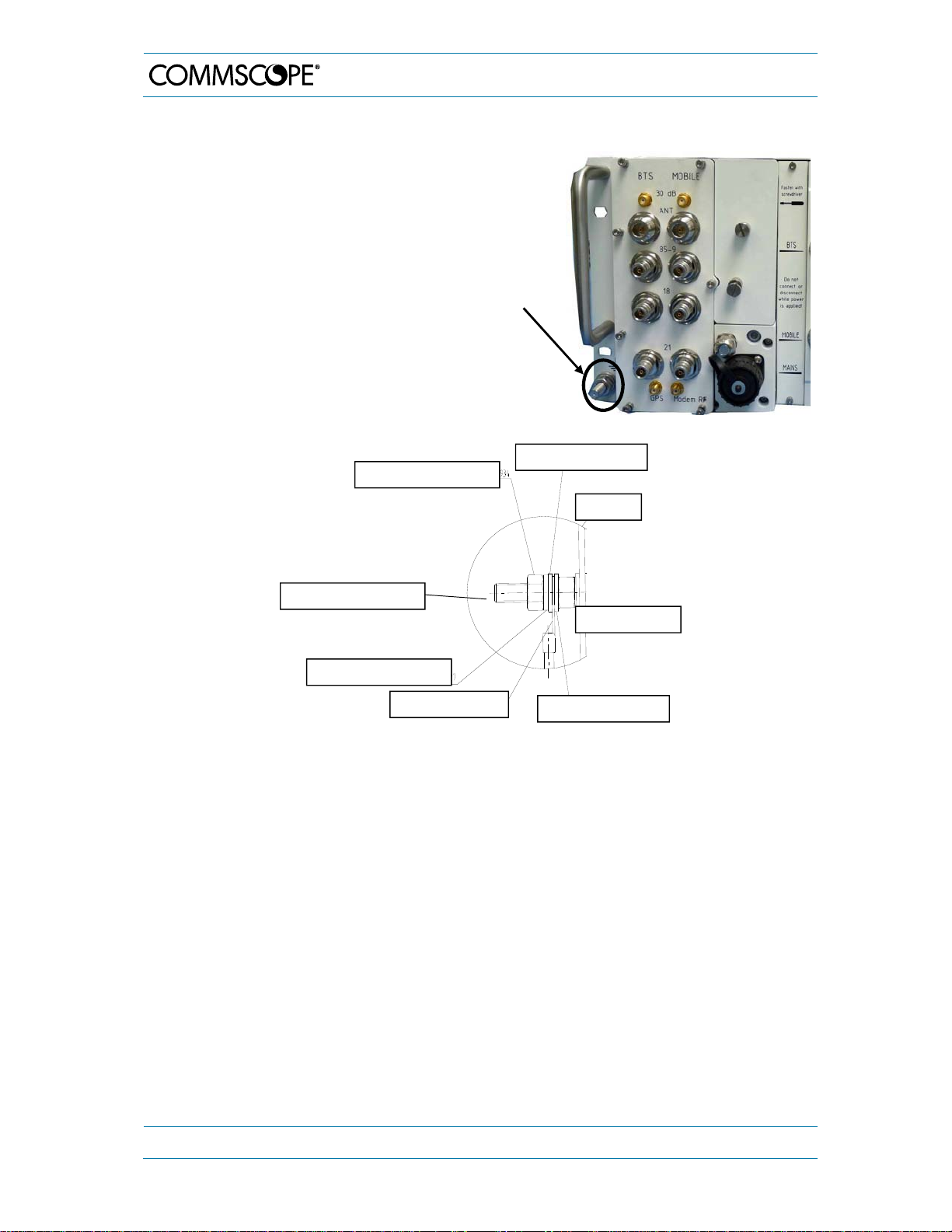
3.2.3. Grounding
Grounding (earthing) must be carried out.
Connect an earth-bonding cable to the
grounding connection provided at the
outside of the unit. Do not use the
grounding connection to connect external
devices.
After loosening the hex nut, connect
the earth-bonding cable between the
two washers, and fasten all parts again
with the hex nut:
Hexagon nut M8 DIN934
3. Installation
Grounding
bolt
Plain washer M8 DIN125
Cabinet
GND bolt M8
Contact washer M8
Locking ring M8 DIN127
Local ground cable
Plain washer M8 DIN125
figure 3-1 Grounding bolt
Note: The PE cables must have a minimum cross section of 16 mm
2
.
The local ground cable requires an adequate ear for the M8 GND bolt.
Page 24 MF0121ACP_uc.docx Manual for Node AM4
Page 25
3. Installation
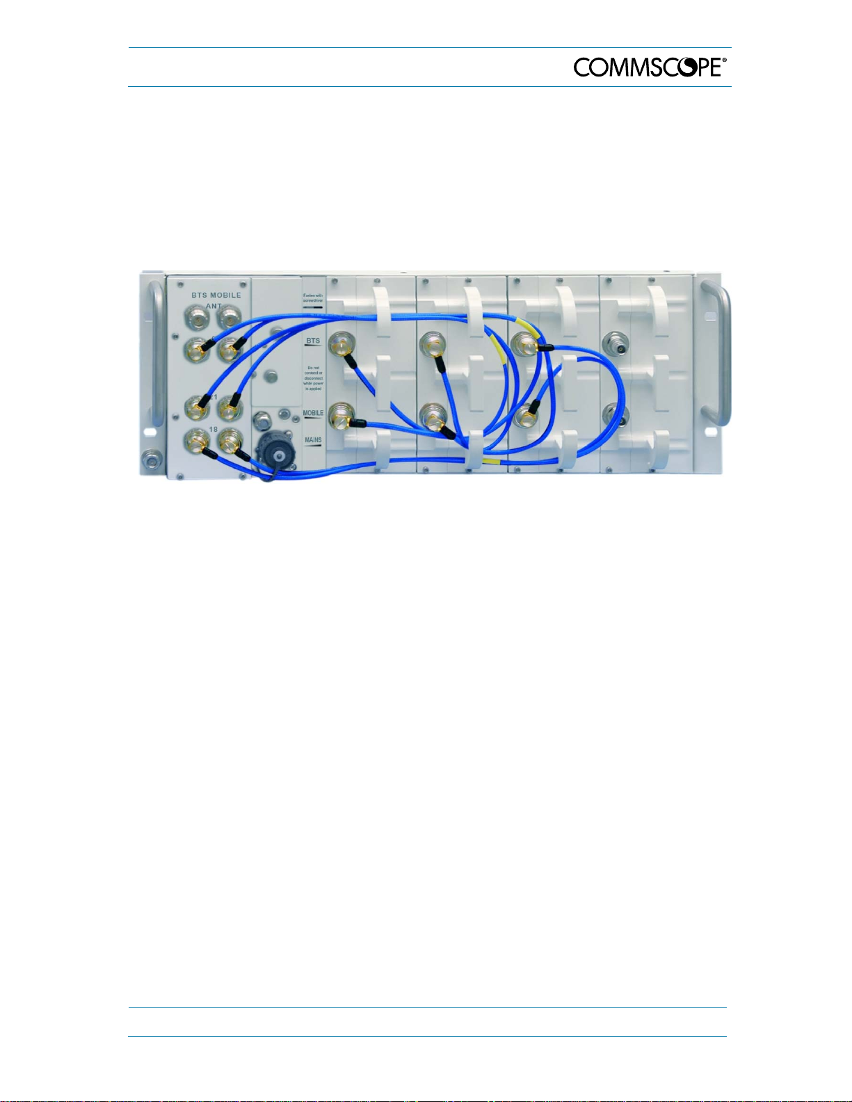
3.2.4. Interconnection Cabling
The required cables are part of the delivery of the RF cards.
Connect the individual BTS band ports of the combiner (if equipped) to the BTS ports of
the according band of the RF cards.
Connect the individual Mobile band ports of the combiner (if equipped) to the Mobile ports
of the according band of the RF cards.
However, the antennas may also be mounted directly on the RF card connectors.
figure 3-2 Example for interconnecting cabling for a Node AM4 (combiner with three
pairs of band ports)
3.2.5. Connection of the Antenna Cables
The antenna connectors of the Node AM combiner are N female. However, the antennas
may also be mounted directly on the RF card connectors which are QN. All connectors
are located at the front of the cabinet.
An operator should refer to the documentation of the cable connector manufacturer for
best mating procedures. Furthermore, the bending radius of the antenna cables should
be maintained at all times.
There are several issues to be considered when selecting the cable and antenna types.
In applications such as trains and ferries, it is highly recommended to use
directional antennas with good front-back-ratios (40 dB is typical) because they
improve isolation and cell-site selectivity.
Smaller diameter cables are less expensive and easier to install but have worse
performance.
MF0121ACP_uc.docx Manual for Node AM4 Page 25
Page 26
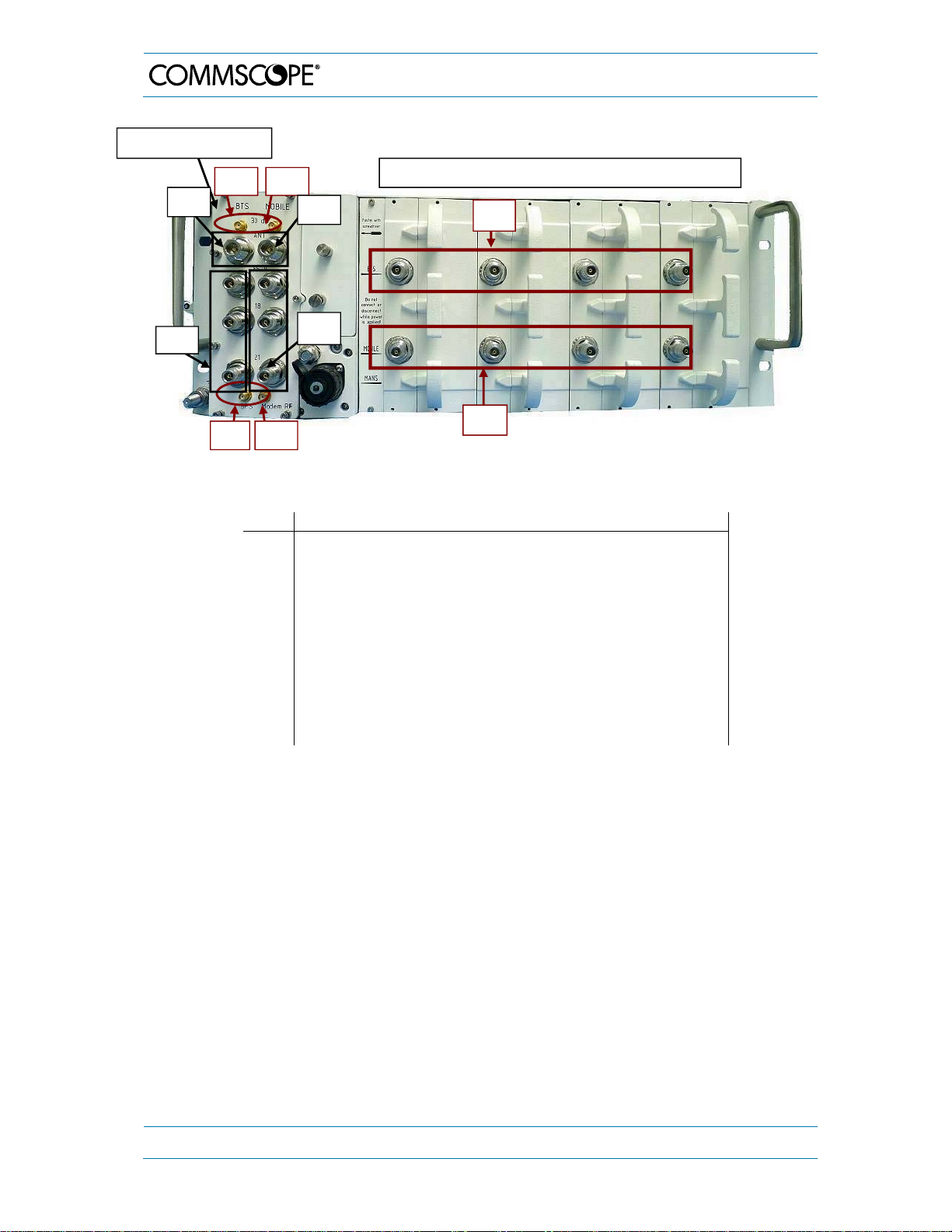
Multiband combiner
1a
2a
1b
2b
Slots 1 2 3 4
5a
3. Installation
4b
3b
5b
3a
4a
figure 3-3 Front view of Node AM4 antenna connections (combiner with three pairs of
band ports)
Description of connector/ port
No.
30 dB coupling probe of antenna ports BTS (for testing only)
1a
30 dB coupling probe of antenna ports Mobile (for testing only)
1b
Antenna connector BTS
2a
Antenna connector Mobile
2b
Band ports BTS *
3a
Band ports Mobile *
3b
GPS port
4a
Modem RF port
4b
BTS ports of RF cards
5a
Mobile ports of RF cards
5b
table 3-1 Description of Node AM4 antenna connectors
* e.g. 900, 1800, 2100; band ports from/to RF cards;
various types of combiner available; examples see chapter 4.3.1
Note:
For special information on MIMO applications contact CommScope Technical Support.
For the location of the antenna connectors (N type), please refer to figure 3-3 Front view
of Node AM4 antenna connections. For mounting the cable connectors, it is
recommended to refer to the corresponding documentation of the connector
manufacturer. The bending radius of the cables must remain within the given
specifications.
Choose the type of cable best suited for the antenna. Consider that a cable with higher
loss is less expensive but impairs performance.
Page 26 MF0121ACP_uc.docx Manual for Node AM4
Page 27

3. Installation
Notice: Use an appropriate torque wrench for the coupling torques:
- for N-type connectors (2 N-m / 20 in lb) with 13/16 in opening,
e. g. item no. 244379 available from the CommScope e-catalog
- for 7/16 DIN-type (25 N-m / 19 ft lb) with 1 ¼ in opening,
e. g. item no. 244377 available from the CommScope e-catalog
- SMA connectors have a specified torque of 60 N-cm.
Do NOT use your hands or any other tool (e.g. a pair of pliers). This might
cause damage to the connector and lead to a malfunction of the unit.
Attention: To minimize passive inter-modulation (PIM) distortion, attention has to be paid
to the physical condition of the connector junctions:
Do not use connectors that show signs of corrosion on the metal surface.
Prevent the ingress of water or dirt into the connector.
Use protective caps for the connectors when not mounted.
Before mounting clean the connectors with dry compressed air.
Before mounting clean the mating surfaces of the connector with a lint-free alcohol-
drenched cloth on a wooden or non-metallic item.
Attach and torque the connectors properly.
Avoid metallic abrasion when mounting the connectors by only screwing the
connecting nut, but not turning the whole connector.
Use a torque wrench to fasten the connector, see above.
Clean the protective caps before mounting for antenna cable replacement.
3.2.6. Cleaning Procedure for RF Cable Connectors
The figures in this chapter illustrate the cleaning procedure and do not show an actual
Node AM.
1. What is needed for the cleaning?
a. Isopropyl alcohol
b. Compressed air
c. Lint-free wipe
d. Cotton buds
2. Remove protective cap from the RF
connector.
MF0121ACP_uc.docx Manual for Node AM4 Page 27
Page 28
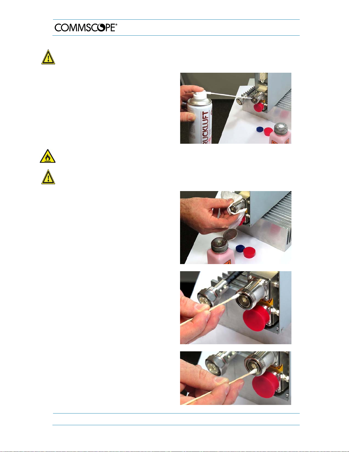
Caution: Risk of injury by flying particles when compressed air is used. Wear
protective clothing, especially protective glasses.
3. Remove metal chips and small
particles from the mating and inner
surfaces of the connector using
compressed air.
Warning: Flammable material. Risk of fire. Keep away from sources of ignition.
Caution: Eye irritant product. Risk of eye irritation. Avoid contact with eyes and skin.
Wear protective clothing, especially protective glasses.
4. Clean the connector winding with lintfree wipe drenched with isopropyl
alcohol.
3. Installation
5. Clean the lip of the inner ring with a
cotton bud drenched with isopropyl
alcohol.
6. Clean the inside surface of the inner
ring with a cotton bud drenched with
isopropyl alcohol.
Page 28 MF0121ACP_uc.docx Manual for Node AM4
Page 29
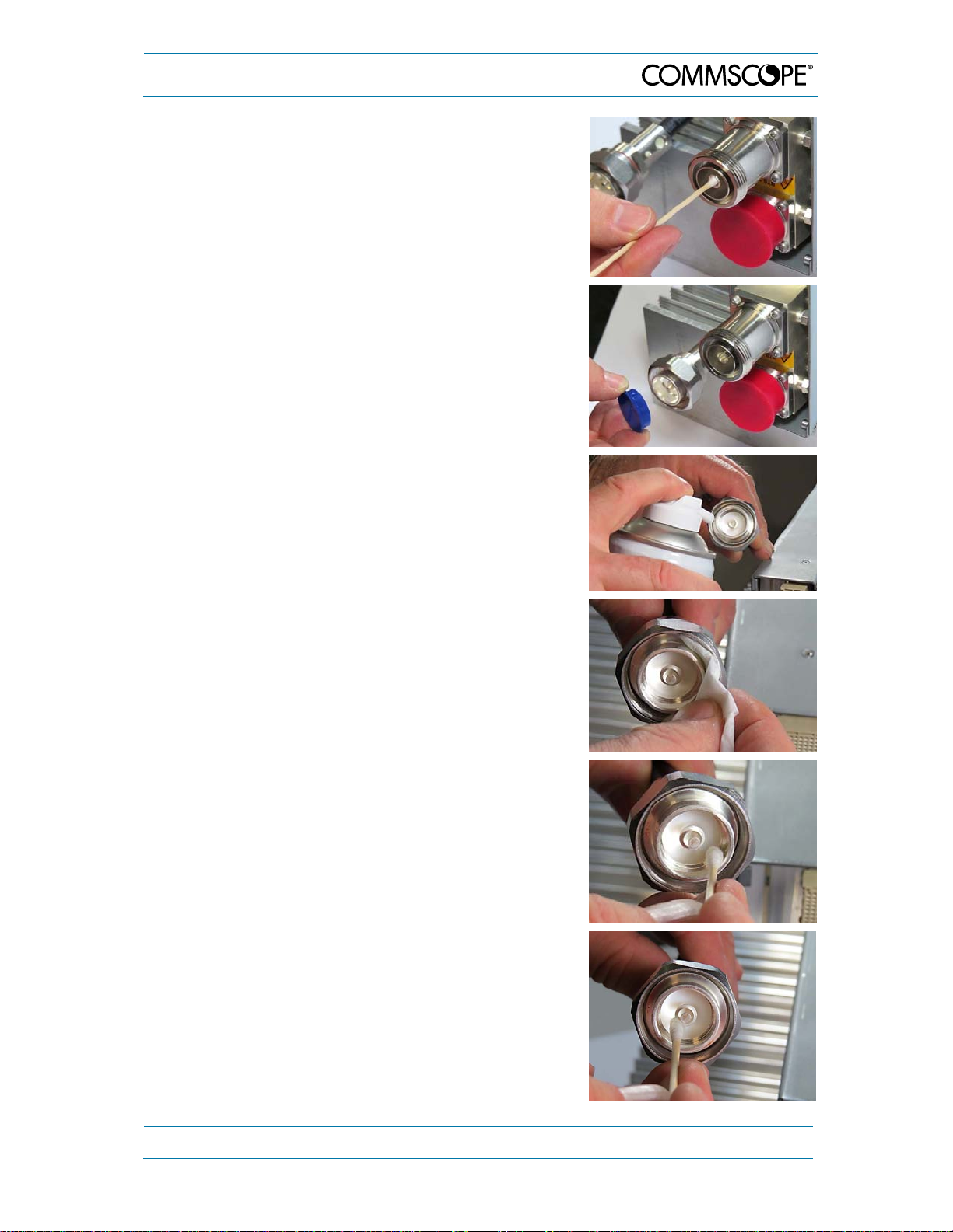
3. Installation
7. Clean the inside of the center
conductor spring tines with a cotton
bud drenched with isopropyl alcohol.
8. Clean in the similar way the connector of the
connected cable. Remove protective cap
from the cable connector first.
9. Remove metal chips and small particles from
the mating and inner surfaces of the
connector using compressed air.
10. Continue with the winding area using lint-free
wipe drenched with isopropyl alcohol.
11. Continue with the inside mating surface of
the inner ring.
12. Clean the outside surface of the center pin.
MF0121ACP_uc.docx Manual for Node AM4 Page 29
Page 30
3. Installation
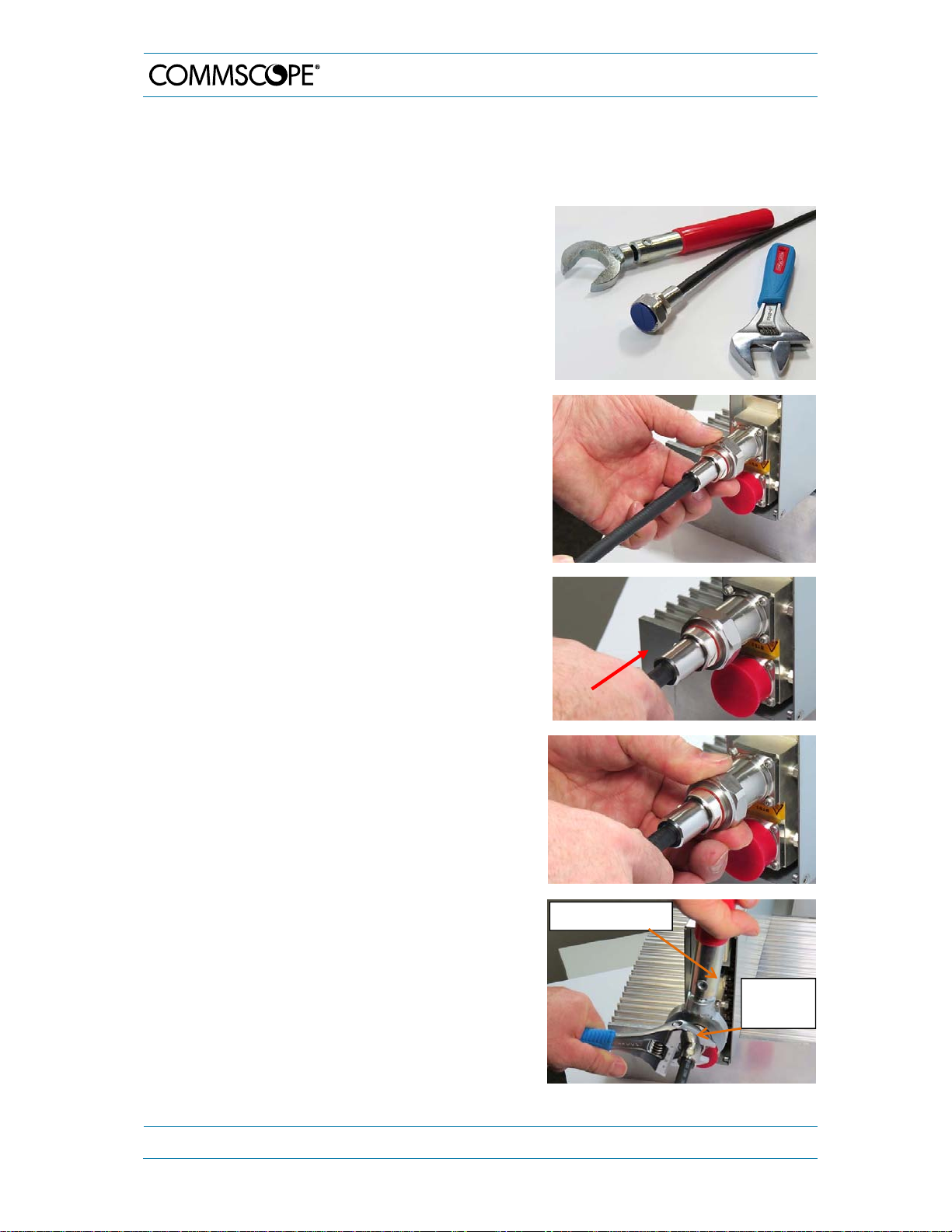
3.2.7. Antenna Cable Connector Assembly
The figures in this chapter illustrate the assembly procedure and do not show an actual
Node AM.
1. What is needed for the connector assembly?
a. Torque wrench.
b. (Adjustable) counter wrench
2. Join the connectors and turn the coupling nut
until the thread grips.
3. Push in the connector until it clicks.
4. Fasten the coupling nut hand-tight. Do not
turn the connector but the coupling nut only.
5. Retain the cable connector with the counter
Torque wrench
wrench and fasten the coupling nut with the
torque wrench until the torque is applied
(torque wrench clicks).
For angled antenna connectors use your
hand to retain the cable connector and fasten
Counter
wrench
the coupling nut with the torque wrench.
Make sure only the coupling nut is turned, not
the cable connector.
Page 30 MF0121ACP_uc.docx Manual for Node AM4
Page 31
3. Installation
r
3
3.2.8. Power Connection
Before connecting electrical power to the unit, the system must be grounded (earthed) as
described in chapter 3.2.3 and connected via external circuit breaker (see table 3-3).
Mains power must be connected at the mains connector. The mains cable (assembled
feed line) is included in the Node AM4.
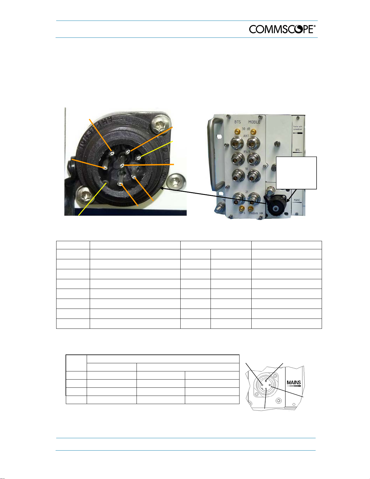
The PIN assignment of the mains connector is as follows:
PIN 2
PIN 3
(PIN 4
n.c.)
PIN 1
PIN 6
Stud
PIN 6
figure 3-4 DC Mains connector, PIN
assignment
PIN 5
Center
figure 3-5 Mains connector, location
Mains
Connector
(remove
cover)
Mains DC connector Mains cable 1* Mains cable 2**
PIN Connection Color Marking Color
1 +V DC grey 1 red
2 +V DC grey 1 red
3 +V DC grey 1 red
4 not connected --- --- --5 -V DC grey 2 black
6 -V DC grey 2 black
Center -V DC grey 2 black
* Grey marking 2 is always the negative potential, grey marking 1 is the positive one.
** Black is always the negative potential while red is the positive one.
PIN
AC Mains Connector
Connection Colo
PIN 1
PIN 2
1 Phase brown black
2 Neutral blue white
3 not connected - -4 PE green / yellow green
PIN
table 3-2 AC Mains connector, PIN assignment
MF0121ACP_uc.docx Manual for Node AM4 Page 31
Page 32

–
A
3. Installation
2
Preferably, a minimum cross section of 4 mm
is required for the power supply
connection.
Each wire must comply with the applicable national regulations regarding loop
impedance, voltage drop, and methods of installation. Make sure to connect the correct
voltage to the unit.
Depending on the Node AM4 power class, please refer for the minimum cross section
of mains cable and external circuit breaker to the corresponding following tables:
Node AM4
(system label) nominal
voltage/ cu rr ent
Node AM4
operating
voltage range
Mains Cable
Cross section
Minimal Recommended
AC 100 - 240 V AC / 8.5 A 85 - 264 V AC 3 x 1.5 mm
DC 680W
PSU
DC 780W
PSU
24 - 110 V DC / 16 A
24 V DC / 9 A
24 – 36 V / 22 A
40
110 V / 15 A
20.4 - 138 V DC
16.8 - 36 V DC
20.4 - 132 V DC
2 x 4 mm2
2 x 2.5 mm
2 x 4 mm
2
--2 x 4 mm
2
2 x 4 mm
2
2 x 4 mm2
2
2
External circuit breaker for Node AM4
AC
DC 680 W PSU
DC 780 W PSU
external, single phase, 50-60 Hz, AC breaker
max. 20 A for 120 V AC; max. 16 A for 240 V AC
external DC breaker, 24/ 48/ 110 V DC, max. 25 A
external DC breaker, 24 V DC, max. 20
external DC breaker, 24 V: max. 32A;
external DC breaker, 48 V / 110 V: max. 25 A
table 3-3 Node AM4, voltage range & external breaker
Note: Do not connect or disconnect the power cord at the mains connector while
power is on. Turn off mains power ** before connecting the power cord at the
unit, then, engage mains again.
** Mains power must be interrupted with an external DC breaker.
Note: Please pay attention when installing the mains power cord. To prevent
heating-up, ensure there is some space between the cables! They must not
be wound up or lay close to each other.
The positioning of the power cable with the
illustrated connector is adjustable by loosening
the 1” lock nut. Use an appropriate torque wrench
(wrench size 27 mm) to observe torque of 2 N-m.
The cable can be turned by maximally 45° to the
left or right from the vertical position as
illustrated. This adjustment degree is irrespective
of the delivery condition which is not necessarily
the vertical position. After the adjustment, tighten
the nut again.
Page 32 MF0121ACP_uc.docx Manual for Node AM4
Page 33

3. Installation
3.2.9. Connection to the Node AM
The Node AM is set up, configured and monitored using a PC. The connection to the
Node AM can be established locally via an Ethernet cable or remotely via modem. The
local connection is easy to set up and much faster in operation. The local connection
should be used for initial setup and whenever the operator is at site.
3.2.9.1. Setting up the Local Connection
A standard Ethernet CAT5 cable is supplied with the Main
Unit of the Node AM. Connect the cable to the Node AM
and the network port on the PC. The Node AM hardware
supports 10 or 100 megabit / sec Ethernet connections.
After the connection is made properly, the red and green
LEDs near the Node AM network connector will flash.
Likewise, the network connector on many PCs has LEDs
that indicate when a hardware connection is established.
The network hardware will determine the highest speed
supported by both devices.
figure 3-6 Connecting the
CAT5 cable to the Node AM for
the local connection
The operating system of most PCs will automatically establish the hardware and software
network connection. No setup or system changes are required on the PC to establish a
local connection with the Node AM.
Normally, the connection can be made either before or after the Node AM and PC are
powered up. If there are problems, make sure the cable is fully inserted at both ends.
Make sure the PC network driver is not fixed at 1 GB/second. With the cable connected
restart the PC. If that fails, restart the Node AM.
3.2.9.2. Setting up the Remote Connection
Setting up the remote connection is slightly more involved than setting up the local
connection. A separate manual is provided to explain how to setup the remote connection.
Via the remote connection, the operator can monitor and control the Node AM using the
Web browser interface remotely.
In addition, the remote connection may be used for an OMC-type software platform and
SMS alarm forwarding.
MF0121ACP_uc.docx Manual for Node AM4 Page 33
Page 34

4. Functional Description
4. Functional Description
4.1. Architecture
The Node AM4 is designed to amplify signals between multiple mobiles and a base
station. The unit consists of a filter and amplifier chain in the downlink and one filter and
amplifier chain in the uplink. The uplink and downlink paths are connected via a duplexer
on both ends of each path. After that the signals are combined by the crossband coupler
with the other frequency bands.
In the uplink path, a signal originating from the mobile is divided by the crossband coupler
into the different frequency bands and is separated from the downlink signal via the UL
IN duplexer. It is then amplified by a low noise amplifier (LNA), which is like the duplexer
part of the RF card. The RF card down-converts the signals to the IF and converts the
analogue signal into a digital signal. Digital filtering / signal processing is done at the main
board of the subrack with single band RF cards, and with dual-band RF cards in the cards
themselves. Then, the digital signal is converted into an analogue signal, is up-converted
and amplified. Finally, the signal is sent to the PA and combined with the downlink signal.
After that the signals from all RF cards are combined at the crossband coupler and
forwarded to the Base Station port of the Node AM4 system.
In the downlink path, a signal originating from the base station is divided by the crossband
coupler into the different frequency bands and is separated from the uplink signal in the
donor duplexer. It is then amplified by a low noise amplifier (LNA), which is like the
duplexer part of the RF card. The RF card down-converts the signals to the IF and
converts the analogue signal into a digital signal. Digital filtering / signal processing is
done at the main board of the subrack with single band RF cards, and with dual-band RF
cards in the cards themselves. Then the digital signal is converted into an analogue
signal, is up-converted and amplified. Finally, the signal is sent to the PA and combined
with the uplink signal. After that the signals from all RF cards are combined at the
crossband coupler and forwarded to the mobile port of the Node AM4 system.
Apart from the difference in digital signal processing as explained in the sections above,
the functionality of dual band and single band RF cards is principally identical in both the
UL and DL paths.
For an overview of the individual components, please refer to chapter 4.3 Components.
4.2. Features
4.2.1. Digital Channel Filters
The Node AM has a multitude of digital filters. The maximum bandwidth of each filter is 5
MHz. If a greater bandwidth than 5 MHz is required, two or more sub-band filters are
linked together without increased amplitude or delay ripple. The number of sub-band
filters is automatically allocated and shown by the repeater software (Technician Setup
page).
The user has to select the downlink start and stop frequencies (wide-band filter load) or
centre frequency and filter bandwidth (narrow-band-filter loads) of each sub-band filter.
For further information regarding sub-band filter settings refer to the User’s Manual for
the Node AM software.
Page 34 MF0121ACP_uc.docx Manual for Node AM4
Page 35

4. Functional Description
4.2.2. Frequency Hopping
The Node AM repeater supports base band hopping (BBH) and synthesized frequency
hopping (SFH) in GSM networks.
For base band hopping (BBH) even channelized digital filters may be used. For
synthesized frequency hopping (SFH) band selective filters are needed.
4.2.3. Filter Types
Please observe that the selectivity of the filter types is not yet available with the current
software version. At the moment only the filter type “Normal” will be active even if another
filter is selected. From which software release onwards the selectivity described in the
following will be implemented in future is not defined, yet.
In future, there will be different filter types available for each sub-band. These filter types
are:
Normal (good selectivity and group delay)
Wide (low selectivity and low group delay)
Narrow (high selectivity and high group delay)
Auto (preferred mode)
It is advisable to select the “Auto” filter. In this case the repeater selects the best filter
type (normal, wide or narrow) automatically. The choice of filter type depends on the input
signal strength and position of the adjacent channel signals.
If narrow, strong adjacent cannel signals are received, the “Narrow” filter is selected. If
the adjacent channels are far from the desired band/channel, the “Wide” filter type is used.
For all other configurations, the “Normal” filter is selected.
4.2.4. Status Information
The Status and Reports menu, which is accessible via the home page of the web
interface, provides information about the current gain, output level and receive signal
strength indication (RSSI) values.
The RSSI provides controlling and monitoring of the receive level of a Base Station (DL
RSSI) or user equipment (UL RSSI) to a Node AM. It measures the level of the input
signal by detecting the RF and converting the analogue level into a digital value. The data
are processed and evaluated by software. A corresponding measurement is also made
for the output levels.
RSSI measurements are done for each band segment; for further details please refer to
the Node AM/ Node AM SW manual.
MF0121ACP_uc.docx Manual for Node AM4 Page 35
Page 36

4. Functional Description
4.2.5. Alarm Forwarding
Alarms can be forwarded from the Node AM to a defined phone number or to the OMC
via the Ethernet port on the UI2 Board (see chapter 4.3.6) or via an optional modem. This
enables the provider to control and to query the status of the network via packet switched,
circuit switched, or LAN connection. Faults and irregularities can be recognized and
eliminated.
With a modem equipped the Node AM also provides an SMS feature, by which the unit
is able to send out alarm messages as SMS. For further details please contact
CommScope.
4.3. Components
The actual configuration of the individual Node AM4 can be seen in the configuration list,
which is part of the delivery. It is also available as an electronic list accessible via
software.
The following figure shows the layout of a system using single-band RF cards only. If one
or more dual-band cards are equipped the only deviation is a different type of multiband
combiner (see figure 4-3).
Modem installed behind combiner
Multiband
combiner
Cable gland
Sealed cover for
user interface,
external alarms,
summary alarm
relay
Status LED
Slots 1 to 4 (from left to right) to house up to 4
independent RF cards, high or medium power level *
RF card * with integrated ** duplexers
figure 4-1 Layout of a Node AM4 (combiner with three pairs of band ports), maximum
equipment
* See also Notes 2 & 3 in chapter 3.1.5 RF Card Installation.
** With certain RF cards, use of a slot duplexer (installed in an RF card slot) is obligatory and maximally
three RF cards are available. For details on RF card types, see chapter 8.
Page 36 MF0121ACP_uc.docx Manual for Node AM4
Page 37

4. Functional Description
4.3.1. Multiband Combiner
The task of the multiband combiner is to combine and to separate the individual frequency
bands received from the common BTS and Mobile port.
The following figures show a examples of multiband combiners for the Node AM4.
o DO NOT use the 30 dB coupling probes [3] for modem connection!
o DO NOT connect the Modem RF probe [1] on the "Mobile" side of the Node AM
repeater with the 30 dB coupling probes [3]!
Front view 3-D-view
3
2
1
figure 4-2 Node AM4 3-band combiner (850-900, 1800, 2100 MHz) with three pairs of
band ports)
MF0121ACP_uc.docx Manual for Node AM4 Page 37
Page 38

4. Functional Description
Front view 3-D-view
figure 4-3 Node AM4 2-band combiner (800-900 and 1800-2100 MHz) with two pairs of
band ports
Via an additional external 10 dB directional coupler the modem can be connected using
the direct Modem RF port [1]. In case an external 10 dB directional coupler cannot be
used, an integrated directional probe (QMA connector at the rear side of the combiner;
see also figure 4-19) may be used to supply the modem with RF signals. :
Further optional ports of the combiner are the GPS port [2] with optional GPS LNA DC
supply (for the corresponding connections on the rear side see also figure 4-19) as well
as two 30 dB coupling probes [3], which can be used for testing purposes for the antenna
ports.
Page 38 MF0121ACP_uc.docx Manual for Node AM4
Page 39

4. Functional Description
4.3.2. Digital Channel Modules (DCM) / RF Cards
The digital channel module (DCM) is the RF digital-converter in both directions for
Downlink and Uplink. The Downlink and Uplink will be separated in the duplexer and the
desired signal will be amplified by an LNA which is – like the duplexer – an integrated part
of the RF card. The RF card down-converts the signals to the IF and converts the
analogue signal into a digital signal. Digital filtering / signal processing is done at the main
board of the subrack with single band RF cards, and with dual-band RF cards in the cards
themselves. Then, the digital signal is converted into an analogue signal, is up-converted
and amplified. Finally, the signal is sent to the PA (internal PA or mounted on the RF card)
and combined with the other link in the second duplexer.
The following figure shows the single band DCM, RF cards:
figure 4-4 Single-band DCM, RF card, low / medium power (left) and high power wit h
additional DL amplifier (right)
Optionally, medium power dual band RF cards
are available, by which two bands, for instance
the 800/900 bands or the 1800/2100 bands,
can be combined in one module. Thus, the
maximum number of bands per Node AM can
be increased to up to 8*.
Apart from the difference in digital signal
processing as explained above, the
functionality of dual-band and single-band RF
cards is principally identical.
* up to 7 with 680 W PSU
figure 4-5 Dual band DCM, RF card (medium power)
With certain RF cards, use of a slot duplexer is obligatory. This duplexer is installed in an
RF card slot, i.e. if such a duplexer is equipped, maximally three RF cards are available.
For details on the card types see chapter 8.
MF0121ACP_uc.docx Manual for Node AM4 Page 39
Page 40

y
4. Functional Description
4.3.3. Dummy Card
figure 4-6 Dummy card
Note: All unused slots need to be assembled with a dummy card for sufficient
airflow and provided IP class.
Note: Empty slots of the Node AM will generate an alarm.
Note: Do not install the dummy card into slot 1.
Note: Depending on type of fan unit (bottom or backside) different dummy cards
need to be equipped in empty slots.
4.3.4. Power Supply Unit
The power supply unit is mounted in the interior cabinet of the Node AM4. This device
transforms mains power into predefined DC voltages. When performing maintenance,
ensure that all circuits are voltage-free and that the Node AM4 is disconnected from
mains.
figure 4-7 Power supply (DC/DC type), front and back
In units with a 680 W power supply (AC or DC), observe the RF card limitations specified
in chapter 7.1. With the 780 W DC PSU there are only limitations for a mains voltage
from 24 to 36 Vdc which are also specified in chapter 7.1. To decide which type of PSU
is equipped, look up the HID of the PSU on the Serial and ID Numbers page of the SW
(PSU IDs see Spare Parts List in chapter 8) or check the power consumption value on
the type label on top of the Node AM:
PSU T
Label:
Page 40 MF0121ACP_uc.docx Manual for Node AM4
pe 680 W 780W
Page 41

4. Functional Description
4.3.5. User Interface Board (UI1 Board)
The UI1 board is used as communication interface between the Node AM controller and
modem or local user, and for general purpose functions of the repeater, as well.
UI
board
inside
figure 4-8 UI-board for general applications, installed
All SW functions available with the general UI1 Board (illustrated above and in figure 4-9)
are part of the SW manual M0121ALx for the Node SW. For special applications, other
types of UI1 Board may be equipped. For these, observe the additional Applications
Notes, which are available on request or included on the Manual CD.
Functions of the UI1-board:
1. Collection of external alarms and summary alarm
2. Status LED
3. Local Ethernet port
4. Voltage supply and communication (RS232/USB) to the modem
5. Battery disconnect push-button to disconnect the internal battery in order to power
down the controller completely or to prevent the battery from complete discharge in
case of system power-down. Observe that an alarm is raised once this button is
pressed and the unit is powered up again. To delete the false alarm, the unit has to be
shut down and powered up again. During shutdown, the battery disconnect button must
not be pressed
The following figure illustrates the general type; of UI1 Board.
(see also notice in chapter 5.2.2).
MF0121ACP_uc.docx Manual for Node AM4 Page 41
Page 42
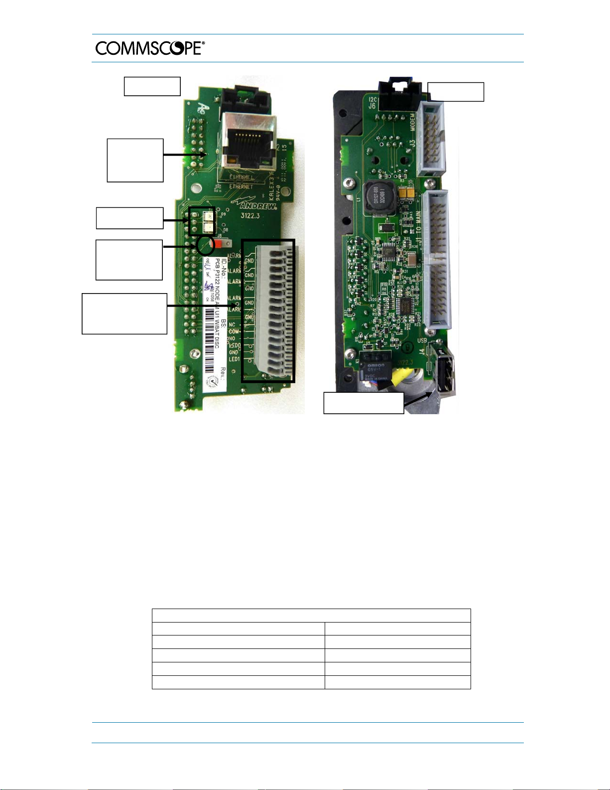
A
A
Top view
Local
Ethernet
connector
Status LEDs
Battery
disconnect
push-button
External alarm &
summary alarm
terminal block
4. Functional Description
Rear view
USB connector
figure 4-9 UI-board for general applications, top and re ar view
4.3.5.1. External Alarms
The external alarms are used to monitor the status of one or more external devices via
the Node AM. A UPS or entry alarm is among the items that might be connected to the
contact relay and monitored via the Node AM4. The cage clamp connectors are located
on the UI1-board.
Observe that the cross-sectional area of the wires to be connected must be in the range
from 0.4 - 0.8 mm
2
(AWG 26-20). Do not use wire-end sleeves.
All external alarms are defaulted to high (3.3V TTL) without connection. This setting may
be changed on the external alarm page to active high or active low. The severity levels of
the external alarms may be set via the web page. More information about the external
alarm settings is available in the web page and online help.
External Alarms 1 to 5
Input voltage range 0 to 5 Vdc
Recommended input line Potential free
Nominal sink current to ground 15 m
ctive level High or low set via software
Connectors Cage clamps
Page 42 MF0121ACP_uc.docx Manual for Node AM4
Page 43

4. Functional Description
)
16 Ext_Alarm_1
15 GND
14 Ext_Alarm_2
13 GND 5
12 Ext_Alarm_3
11 GND
10 Ext_Alarm_4
Summary Alarm:
normally closed PIN
6
(open in alarm
condition) *
Summary Alarm:
common pin
Summary Alarm:
normally open PIN
4
(closed in alarm
condition
9 GND 3 LED_UI0
8 Ext_Alarm_5 2 GND
7 GND 1 LED_UI1
* galvanically isolated
figure 4-10 PIN assignment
*
External
alarm
clamps
figure 4-11 Schematics of external alarm clamps
MF0121ACP_uc.docx Manual for Node AM4 Page 43
Page 44

4. Functional Description
There is one external cable gland at the front of the Node
AM, which may be used to connect the external devices.
The recommended cable diameter for the connection
cable is 4 - 6 mm. Please note that connecting the
external devices by a wrong type of cable may result in a
loss of the watertightness.
All external alarms are defaulted to high (3.3V TTL)
without connection. This setting may be changed on the
external alarm page to active high or active low. The
severity levels of the external alarms may be set via the
web page. More information about the external alarm
settings is available in the web page and online-help.
figure 4-12 External cable gland
Make sure that external alarms which are not required are set to active low or disabled;
otherwise the status will always show an alarm.
The names for each external alarm are user-definable on the external alarm page;
renaming them to indicate the use of these alarms is recommended.
4.3.5.2. Summary Alarm
Note: With alarm severity setting 'disabled' it is possible to decide which alarms do
not activate the summary alarm. For more details please refer to the Node AM/
Node AM Software manual that is part of the delivery.
The summary alarm is a DC potential-free contact relay.
Observe that the cross-sectional area of the wires to be connected must be in the range
from 0.4 – 0.8 mm
2
(AWG 26-20).
Pin No.:
6
5
4
figure 4-13 Summary alarm relay
Page 44 MF0121ACP_uc.docx Manual for Node AM4
Page 45
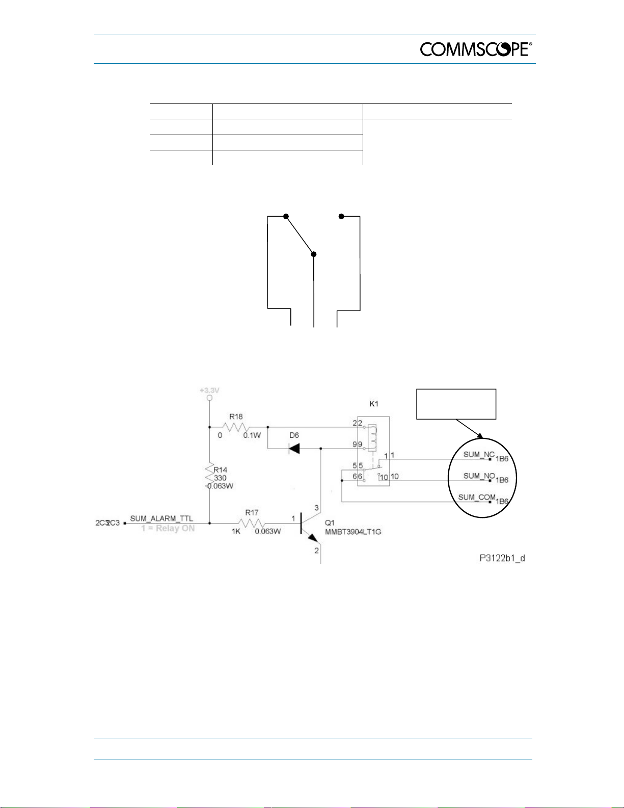
4. Functional Description
The following table describes the three-connector PIN out.
Pin No. Contact Maximum Resistive Load
4 Open in normal condition
5 Common
Max. 0.5 A @ 60 VDC
6 Closed in normal condition
table 4-1 Pin assignment of relay contacts
Pin 4
Pin 5
Pin 6
figure 4-14 Relay contacts, alarm condition
Summary
alarm clamps
figure 4-15 Schematics of summary alarm clamps
MF0121ACP_uc.docx Manual for Node AM4 Page 45
Page 46
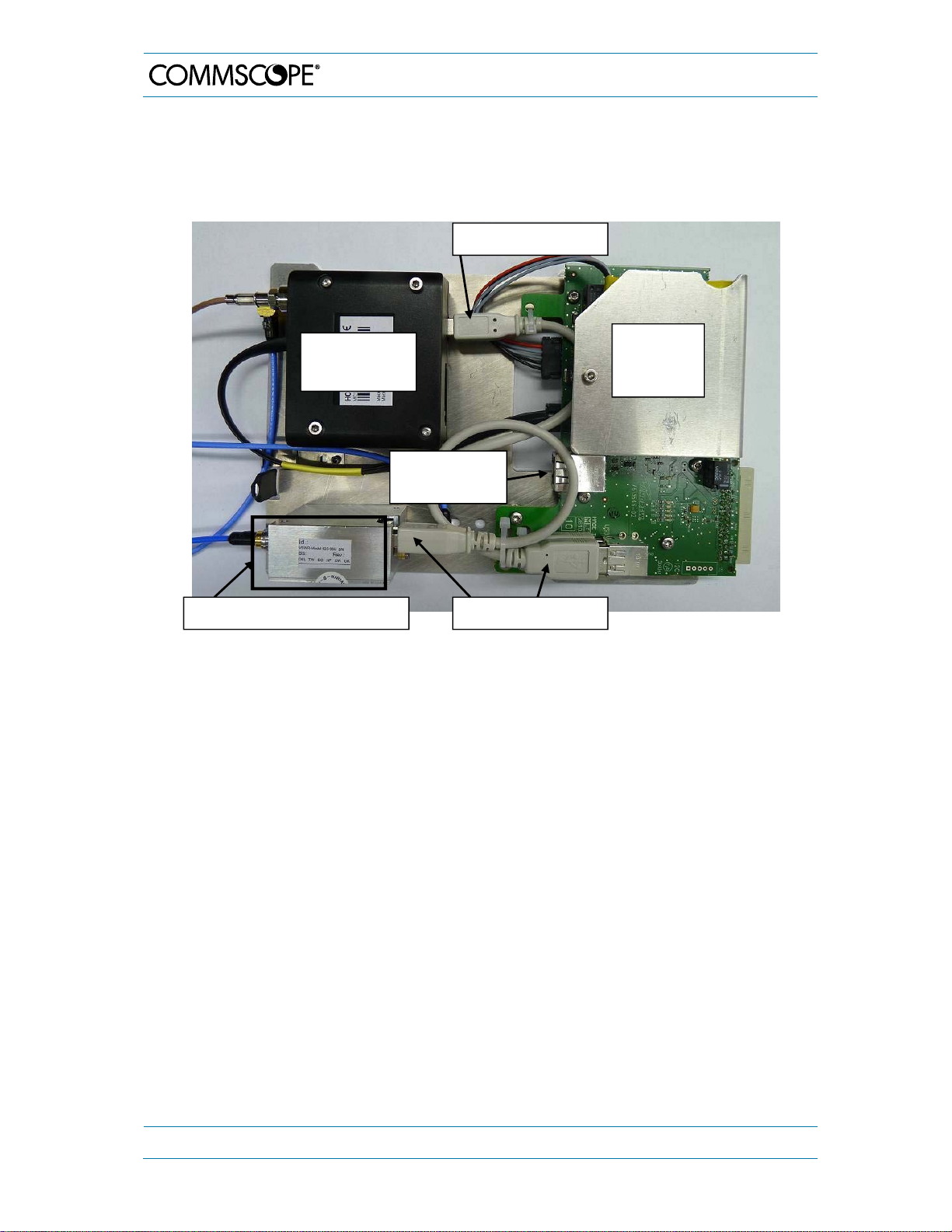
4. Functional Description
4.3.6. User Interface 2 Board with Optional Features
The User Interface 2 (UI2) board is equipped on a carrier plate together with the optional
features of the Node AM4. These are the VSWR module, the Battery Backup option, and
the modem. Besides, the UI2 board offers additional USB ports and an Ethernet port.
USB connector
Optional
modem
Battery
Backup
option
Ethernet
connector
VSWR module (optional)
USB connectors
figure 4-16 UI2 Board kit, layout
UI2 board revisions are supported by certain SW versions, i.e. new HW revisions may
not be supported by older SW versions. In case of such an incompatibility of HW and SW
the message “User Interface 2 HW failure” will be prompted.
4.3.6.1. VSWR Module Option
The VSWR module monitors the VSWR of the Node AM4 coverage port. The module
communicates with the controller through USB while measuring the forward and reverse
RF signal at the combiner output.
4.3.6.2. Battery Backup Option
The battery backup unit (BBU) including the battery pack is installed on top of the User
Interface 2 (UI2) board and located underneath the cover sheet. The BBU ensures that
the Node AM4 can log-off from a Network Management system in case the mains voltage
will be switched off.
Page 46 MF0121ACP_uc.docx Manual for Node AM4
Page 47
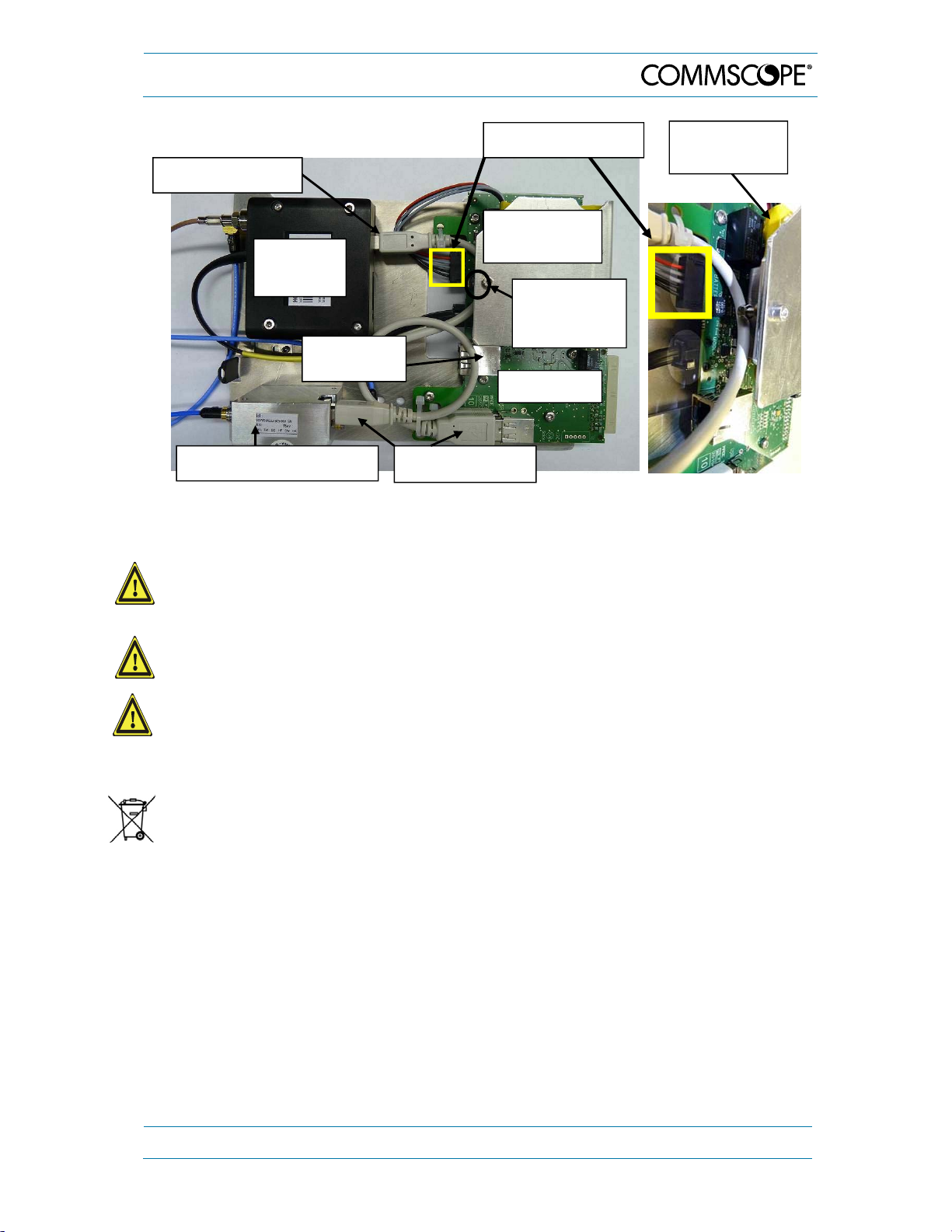
4. Functional Description
USB connector
Modem
(optional)
connector
Ethernet
Battery connector
BBU
cover sheet
Hexagon
socket-headcap screw
UI2 board
Battery pack
underneath
VSWR module (optional)
USB connectors
figure 4-17 Position of UI2 Board and BBU
Note: We recommend replacing the battery pack after 4 years of operation.
1. Caution: Electrolyte inside. Risk of health hazards associated with electrolyte leakage.
Do not disassemble, puncture, modify, drop, throw, or cause other unnecessary shocks
to batteries.
2. Caution: High current if shorted. Risk of injury by high current. Do not short circuit the
batteries.
3. Caution: The batteries might be hot. Risk of burns by hot surface. Do not touch the
batteries before they have sufficiently cooled down.
Notice: For the replacement procedure, also observe the health and safety warnings
in chapters 5.1 and 5.2.1 as well as the notes in chapter 5.2.
Do not put the batteries to the garbage but dispose of them properly according local
and/or regional regulations.
To replace the battery pack, first uninstall the multiband combiner as explained in
chapter 5.2.1. Then, proceed as follows:
Unplug the complete module on which the battery pack is installed. Disconnect the
battery cable at the UI2 board.
Just loosen the M3x16 hexagon socket-head-cap screw on top of the cover of the
battery pack. It is not necessary to unscrew this screw entirely!
Then the battery pack can be removed easily.
Insert the new battery pack and fasten the M3x16 hexagon socket-head-cap screw
again.
Reconnect the DC connector to the "Battery" connector at the UI2 board.
MF0121ACP_uc.docx Manual for Node AM4 Page 47
Page 48

4.3.6.3. O pti onal Modem s
4. Functional Description
Note: As optional modem, different types can be used for the Node AM: PHS8
(successor of HC25), PLS8 (for LTE), TRM-5, and MC88 modems. The layout
of all types is alike. In the following, the general term "modem" is shortly used,
referring to any of these types. GPS is only supported by PHS8 (formerly HC25)
and PLS8. Modem type RV50X is supported but it is not available from
CommScope. It can only be ordered directly from the manufacturer.
A wireless modem is used to establish a remote connection to the Node AM. The
connection may be circuit switched or packet switched and is used to change the
parameters of the unit, check and clear alarms, or collect measurement and quality
statistics. Furthermore, the modem is requested at the Node AM to alert the operator
when there is an alarm.
The modem settings (i.e. which type of modem, Initstring, etc.) may only be changed
locally. Should a different modem be used, the operator should ensure that the settings
are changed prior to leaving the site.
For technical data of the individual modems, see chapter 7.5.1 HC25 / PHS8 / PLS8 /
MC88 / TRM-5. For the technical data of type RV50X, refer to the data sheet of the
manufacturer.
Initstrings
The initialization string (abbreviated by initstring) depends on the operator’s network and
the modem. It may be necessary to adjust the initstring in the field.
When a modem is selected in the Node AM web interface the default initstring for this
modem is suggested. The initstrings for the different modems are listed in the software
description for the Node AM.
Modem Installed (valid for HC25 / PHS8 / PLS8 / MC88 / TRM-5)
The modem allows remote control and
maintenance of the Node AM.
Parameters may be changed; alarm and
measurement statistics may be
acknowledged and collected by the
OMC.
The modem is installed in the side tube
of the unit. To avoid a collision between
modem connectors and combiner
(especially with 4-way combiners), an
adapter kit for modem installation is
used (see chapters 5.2.2 and 8).
figure 4-18 Modem installed, exemplary
Page 48 MF0121ACP_uc.docx Manual for Node AM4
exemplary
Page 49

4. Functional Description
The modem output is connected to the modem coupler port on the rear side of the
multiband combiner, or – in case an external modem antenna or directional coupler is
used – to the modem RF port; see following exemplary illustration:
RF coupling port
10 dB at combiner
exemplary
Multiband
combiner
RF cable
RF input of
HC25 / PHS8 /
PLS8 modem
Modem RF port
DC supply connector
for GPS LNA option
figure 4-19 Cable from the modem to the multiband combiner, exemplary
Connect the wires, cables and connectors of the HC25 / PHS8 / PLS8 modem kit
according to the following wiring illustration (both types are identical except the fact that
the RS232 connector must not be used with the PHS8/PLS8 types):
to UI2 Board
Cable AC/DC USB
0.27m USB Typ A
M3.0x 35mm hexagon
socket-head-cap screw
Cable AC/DC
AWG26 240 mm
6-wires
UMTS Modem
Siemens HC25T
to UI2 Board
not used
Cable RF RG-316 0.3m
FME female straight
to combiner
to UI2 Board
All unmarked screw joints:
nominal-tightening torque values
according to QA 7.5.1.090/F1011P0
Part(s) to be clean and free of all chips,
burrs, sharp edges and foreign material
G3266M381
figure 4-20 Modem Kit HC25 / PHS8 / PLS8 Node AM, schematic wiring
MF0121ACP_uc.docx Manual for Node AM4 Page 49
Page 50

4. Functional Description
Connect the wires, cables and connectors of the MC88 / TRM-5 modem kit according to
the following wiring illustration:
M3.0x 35 mm hexagon
socket-head cap screw
GSM Modem Cint.
MC88-T/EGS5
to UI1 Board
Ribbon-cable harness
14-wires
not used
* for position on UI1 Board see figure 4-22
Cable RF RG-316 0.3 m
FME, female, straight
Cable AC/DC AWG26
240 mm 6-wires to UI2
Board
All unmarked screw joints: nominal tightening
torque values according
to QA 7.5.1.090/F1011P0
Part(s) to be clean and free of all chips,
burrs, sharp edges and foreign material
G3266M379
figure 4-21 Modem Kit MC88/TRM-5 Node AM, schematic wiring
* Connector on UI1 Board for
RS232 cable to
MC88/TRM-5 modems
figure 4-22 UI1 Board, position of modem RS232 connector
SIM Card
To insert the SIM card, use a pen and press the small yellow button.
Then, the SIM-card drawer will come out and the SIM-card can be inserted.
Carefully push the drawer to its original position.
-
Yellow button
figure 4-23 SIM-card dra w er
Page 50 MF0121ACP_uc.docx Manual for Node AM4
Page 51

4. Functional Description
Installation of modem RV50X
This modem type is not available from CommScope. It can only be ordered directly from
the manufacturer. For the installation, proceed as illustrated in the following:
figure 4-24 Installation of modem RV50X
MF0121ACP_uc.docx Manual for Node AM4 Page 51
Page 52

5. Maintenance
5. Maintenance
5.1. General
Read and observe chapter 1.2.
Caution: The unit reaches high temperature in operation. Risk of burns by hot
surface. Do not touch the unit before it has sufficiently cooled down.
Notes:
The Node AM does not require any preventative maintenance measures apart from
the Battery Backup Unit (BBU). It is recommended to replace it after 4 years of
operation (see chapter 4.3.6).
We recommend checking the cleanliness of the unit and in particular of the fan unit at
appropriate intervals depending on the degree of dust and dirt at the installation site. If
necessary, any dusty or dirty areas / parts should be cleaned at regular intervals, which
also depend on the degree of dust and dirt at the installation site.
For cleaning, the following procedure is recommended: use an industrial vacuum
cleaner and, first, vacuum the outside of the unit. For inside cleaning, remove all plugin units (as well as the fan unit) according to the instructions in the following chapter,
and then, vacuum the fan unit, the cooling fins of the plug-in units as well as the
complete interior of the Node AM.
In the event of a malfunction, the user should check the status of the antennas, feeder
cables, connectors, and mains power before replacing any components.
When sending back the unit, use an appropriate packaging; see chapter 7.3. We
strongly recommend using the original packaging. The transport protection cover (see
chapter 3.1.3) should also be installed for units with bottom type fan unit (see chapter
5.2.7.2). For a better shock protection of the DC connectors and main board the RF
cards must be packed separately.
5.2. Replacement of Components
Read and observe chapter 1.2.
Maintenance of the Node AM should be performed on a field replaceable unit (FRU) basis
only. Do not damage the warranty labels on the components as this voids the warranty.
Unless otherwise agreed to in writing by CommScope, CommScope’s general limited
product warranty (http://www.commscope.com/Resources/Warranties/) shall be the
warranty governing the Node AMs, including the installation, maintenance, usage and
operation of the Node AMs.
The spare parts list contains only units that can be replaced without tuning or soldering
work. It is not recommended to replace any components inside the Node AM itself,
except, RF cards, combiner, and modem. Regarding the replacement of a PSU observe
the corresponding Note in chapter 5.2.5.
Note: Defect parts should only be replaced by original parts from the supplier. All
interventions inside the housing are at one’s own risk.
Page 52 MF0121ACP_uc.docx Manual for Node AM4
Page 53

5. Maintenance
e
e
Note: During maintenance ensure that the unit has been disconnected from mains.
Note: Before disconnecting any cables, label any unlabeled cables to ensure
correct reconnection, and check the switch positions of the removed part to
set the switches of the new part accordingly.
To replace an FRU, use the appropriate tools. The tools are provided along with the
equipment. Replacement tools may be ordered from the supplier.
SMA connectors have a specified torque of 60 N-cm. All screws have a right-hand thread,
turn the tool clockwise for tightening and counter-clockwise for loosening. Use an
appropriate tool to fasten and unfasten connectors and screws. Do NOT overtighten the
connectors or screws!
The tables below show various screws with their respective torques.
Locking Torques for Stainless Steel Screws
Thread Ø Nominal torqu
M 2.0 0.40 N-m
M 2.5 0.82 N-m
M 3.0 1.45 N-m
M 4.0 3.30 N-m
M 5.0 6.50 N-m
M 6.0 11.00 N-m
M 8.0 27.00 N-m
table 5-1 Specified torques for stainless steel screws
Standard Torques for Neck-collar Screws
Thread Ø Nominal torqu
M 3.0 1 N-m
M 4.0 3.3 N-m
M 5.0 6.05 N-m
table 5-2 Standard torques for neck-collar screws
Standard Torques for Metal Cable Glands
Thread Ø Nominal torque to housing or nut Nominal torque sleeve nut
M 16 x 1.5 20.00 N-m 15.00 N-m
M 20 x 1.5 30.00 N-m 20.00 N-m
PG 7 6.50 N-m 0.42 N-m
table 5-3 Standard torques for metal cable glands
MF0121ACP_uc.docx Manual for Node AM4 Page 53
Page 54

g
Specified Standard Tolerances
5. Maintenance
Nominal torque
ran
e
≤ 0.5 N-m ± 0.05 N-m
≤ 1.0 N-m ± 0.10 N-m
≤ 1.5 N-m ± 0.15 N-m
≤ 2.0 N-m ± 0.20 N-m
≤ 3.0 N-m ± 0.30 N-m
≤ 4.0 N-m ± 0.40 N-m
≤ 5.0 N-m ± 0.50 N-m
Prescriptive
limits
Nominal torque
range
≤ 6.0 N-m ± 0.60 N-m
≤ 8.0 N-m ± 0.70 N-m
≤ 11.0 N-m ± 0.90 N-m
≤ 20.0 N-m ± 1.50 N-m
≤ 35.0 N-m ± 2.00 N-m
≤ 50.0 N-m ± 3.50 N-m
Prescriptive limits
table 5-4 Specified standard tolerances
Note: Terminate each open RF connector by 50 ohms, to avoid internal oscillation.
Note: Observe that all components have watertight sealings.
After replacement of components all screws have to be fastened tight to
ensure watertightness.
Note: After the replacement of a component, check whether the system has to be
levelled anew.
Note: Do not forget to reinstall the splash water shield and vandalism cover (if this
option is installed) after the replacement procedure to ensure safe operation.
Note: It is recommended to disconnect the Node AM from mains (power-supply
line) before an RF card is mounted or dismounted. In case the Node AM is
not allowed to be disconnected from mains, the RF card which needs to be
replaced must be disabled via software in the Technician page before
removing it. This is to avoid possible damage when inserting the new RF
card.
If any FRU not contained in the following chapter needs to be replaced, please contact
customer service for additional instructions.
Page 54 MF0121ACP_uc.docx Manual for Node AM4
Page 55

5. Maintenance
5.2.1. Multiband Combiner
Danger: Electrical hazard. Danger of death or fatal injury from electrical current
inside the unit in operation. Before opening the unit, disconnect mains power.
Danger: Electrical hazard. Danger of death or fatal injury from electrical current
due to a possible short-circuit caused by incorrect handling. Make sure the
system has been correctly grounded (earthed) as described in chapter 3.2.3 and
connected via external circuit breaker (see chapter 3.2.8).
Caution: Rotating fans. Risk of injury in operation. Wear tight-fitting clothes and
disconnect mains before working inside the unit.
Note: Removal and installation of a combiner on-site must only be done by a service
technician of CommScope or by a qualified person authorized and trained for
this procedure who is observing the corresponding safety procedures required
by local, regional and country-specific regulations which have to be observed
during all times of this procedure.
Notes:
The figures in this chapter show the
combiner type with three pairs of band
ports. The procedure is exactly the same for
combiners with two band port pairs.
Unscrew the combiner and pull it out
carefully with your hands.
As the long hole of the combiner’s carrier plate is hooked into a screw of the modem
mounting plate, this is pulled out to a certain degree, as well:
Mounting plates of combiner and modem connected by
screw locked into long hole (seen from both sides).
MF0121ACP_uc.docx Manual for Node AM4 Page 55
Page 56

A
Unhook the plates and disconnect all cables from the combiner. Remember their
positions for later reconnection. (For replacement of components on the carrier plate, now
refer to the corresponding chapter.)
t four band combiners, the combiner is tied to the
carrier plate by a mounting plate that is fixed with
screws. To avoid a collision between modem
connectors and combiner (particularly with 4-way
combiners), an adapter kit for modem installation
is used (see figure 5 1 and chapter 8).
Exchange the combiner and re-connect all cables
at the correct positions.
5. Maintenance
Note: In case of upgrading with a different type
of multiband combiner, make sure that the
operating frequency band of the modem still fits to
the combiner frequency bands.
Caution: Before sliding the new module in, make sure that no cables inside, e. g. from
the PSU, obstruct the way and may get squeezed or damaged in the process. Make
also sure that no cables get disconnected by accident. In case of obstructing cables
that may get damaged, send the unit back to the supplier for repair.
Carefully slide in the modem carrier plate, using
the guide rails provided at the top and bottom of
the slot for positioning the module correctly.
Then, reconnect the modem and combiner plates
by hooking the screw of the modem plate into the
long hole of the combiner plate.
Guide rails
Position the combiner plate in the same guide rails
as the modem plate and slide in the combiner
carefully, also pushing the modem carrier plate
back in.
Attention: Be careful with all cables connected. Do not squeeze or damage any cables,
and make sure that no cables get disconnected by accident.
Fasten the screws of the combiner tight to restore watertightness (for screw positions,
see illustration at the beginning of the procedure).
Page 56 MF0121ACP_uc.docx Manual for Node AM4
Page 57

5. Maintenance
5.2.2. Modem / Battery
1. Caution: Electrolyte inside. Risk of health hazards associated with electrolyte
leakage. Do not disassemble, puncture, modify, drop, throw, or cause other
unnecessary shocks to batteries.
2. Caution: High current if shorted. Risk of injury by high current. Do not short circuit the
batteries.
3. Caution: The batteries might be hot. Risk of burns by hot surface. Do not touch the
batteries before they have sufficiently cooled down.
Do not put the batteries to the garbage but dispose of them properly according local
and/or regional regulations.
Notice:
Currently, the battery condition is only detected at shutdown, by making sure the battery
has enough charge to allow a complete shutdown process. If the battery is dead,
missing, or not able to hold a charge lasting more than a minute or two (the time for a
normal shutdown, which could be up to 10 minutes), this will be noticed by the software
at the next power up and an alarm raised. However, this means a “good” battery
condition can also only be detected at shutdown. If a bad battery is replaced with a good
battery in the field, the alarm will not be cleared immediately at the next bootup. Instead
the system will have to have a normal power shutdown and then the alarm will be cleared
at the following bootup. So, the procedure for replacing a failed battery should be:
1. Shutdown the system.
2. Replace the battery.
3. Power up (alarm will still be raised).
4. Shutdown the system.
5. Power up (alarm will now be cleared).
If this is not done, the alarm will be only cleared after the next shutdown and power up
event of the system. Also, observe that an alarm is raised once the battery disconnect
button on the UI1 board is pressed and the unit is powered up again. To delete the false
alarm, the unit has to be shut down and powered up again. During the shutdown, the
battery disconnect button must not be pressed.
Notice: For the replacement procedure, also observe the warnings in chapters 5.1 and
5.2.1.
Notice: For tightening
SMA connectors, always
use an appropriate torque
wrench:
Modem and battery are located on a carrier plate located behind the combiner carrier
plate. Thus, for replacing the modem or the battery, the combiner has to be removed
first. To do so refer to chapter 5.2.1, observing the corresponding warning messages.
MF0121ACP_uc.docx Manual for Node AM4 Page 57
Page 58

5. Maintenance
The long hole of the combiner’s carrier plate is hooked into a screw of the modem
mounting plate, so both plates will be pulled out together:
Mounting plates of combiner and modem connected by
screw locked into long hole (seen from both sides).
Unhook the plates and disconnect
all cables from the combiner.
Then, also carefully pull out the modem carrier
plate completely, as well.
Remember their positions for later
reconnection.
For battery replacement, please refer to chapter 4.3.6 Fehler! Verweisquelle konnte
nicht gefunden werden..
To replace the modem, proceed as follows:
Carefully disconnect all cables from the
exemplary
Cable tie
modem and remember their positions for
reconnection.
Note: In some cases, a cable tie (as
illustrated to the right) might be used.
Cutting this cable tie is not necessary if
you proceed exactly in the order as
described in the following
Page 58 MF0121ACP_uc.docx Manual for Node AM4
Page 59

5. Maintenance
Unscrew the two hexagon sockethead-cap screws M3x30 of the
modem (circle-marked in picture to
the right).
Then, re-connect all cables at the new
modem (see also schematic wiring
illustrations in Fehler! Verweisquelle
konnte nicht gefunden werden. and
2 screws
M3x30
Fehler! Verweisquelle konnte nicht
gefunden werden.) *.
Note: When replacing a HC25
modem with the PHS8 type, observe
that the RS232 connector must not be
used with the PHS8.
* In case of an upgrade with the new adapter kit (see also chapter 8), mount the new
modem onto the adapter kit as illustrated in the following figure:
figure 5-1 Installation of modem onto adapter kit
MF0121ACP_uc.docx Manual for Node AM4 Page 59
Page 60
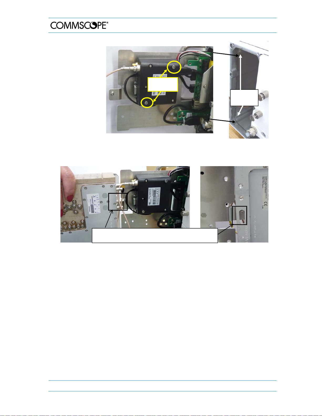
g
5. Maintenance
Screw the new
modem to the
carrier plate with
the two hexagon
socket-head-cap
screws M3x30.
Insert the carrier
plate of the
modem into the
2 screws
M3x30
Guide
rails
guide rails and
carefully push it
in, however not
completely.
First, reconnect all cables between combiner and modem. Then, reconnect the combiner
and modem carrier plates by hooking the screw of the modem mounting plate into the
long hole of the combiner plate:
Mounting plates of combiner and modem connected by
screw locked into lon
hole (seen from both sides).
For the final installation of both, refer to the explanation in chapter 5.2.1, strictly observing
the corresponding warning messages.
Page 60 MF0121ACP_uc.docx Manual for Node AM4
Page 61
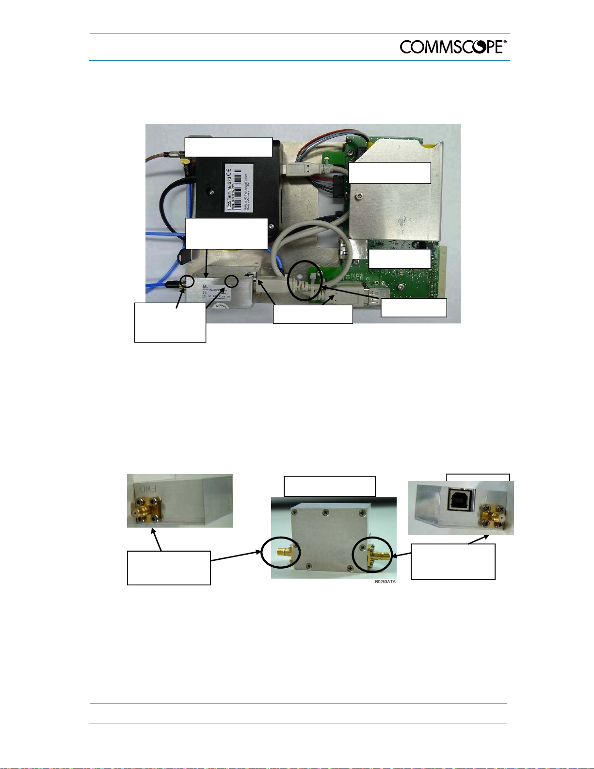
5. Maintenance
5.2.3. VSWR Module (Optional)
The VSWR module is located on top of the modem plate. For removing and inserting the
plate, refer to chapter 5.2.2.
Optional modem
Optional BBU
VSWR module
(optional)
UI2 board
Two M3x10
screws
underneath
USB connector
Cable tie
figure 5-2 VSWR module, layout
To replace the optional VSWR module, proceed in the following order:
Unscrew the two M3x10 counter-sunk head screws underneath the rear side of the
modem plate.
Cutting the cable tie is not necessary if you carefully disconnect the USB
connectors and RF cables before taking out the module.
Note: Make sure to remember their correct positions according to the
RF connectors labeled with FWD (Abbrev. for FORWARD - left) and
REV (Abbrev. for REVERSE - right), see following illustrations:
RF connector
"FWD"
figure 5-3 VSWR module, position of RF connectors
VSWR module
RF connector
"REV"
Insert the new VSWR module and proceed in reverse order, i.e. fasten the two
screws again from below and reconnect the USB and RF cables.
Note: Be careful with the RF connectors! Do not confuse REV and FWD
connectors! Ensure to re-connect the FWD-RF connector and cable to
their correct positions before the replacement, (as illustrated in figure
5-3 VSWR module, position of RF connectors).
MF0121ACP_uc.docx Manual for Node AM4 Page 61
Page 62

g
5. Maintenance
5.2.4. Status LED
For local supervision, a status LED located at the front at the sealed cover of the Node
AM UI1 board gives an indication of the summary alarm.
This three-color LED provides visual
equipment status information:
Green Normal operation condition
Red Summary alarm, critical
Yellow Summary alarm, uncritical
Check the cables to the external
Status
LED off
alarm connector.
Check mains cabling.
Check mains power.
figure 5-4 Cover of UI-card with status LED
If the status LED is not required,
first unscrew the sealed cover and then
disconnect the three connection cables
(indicated in the figure above) from the
(external alarm) terminal block.
After replacing the cover, fasten the screws
tight to restore watertightness.
fi
ure 5-5 Status LED and connection cables
Sealed cover
Status LED
Page 62 MF0121ACP_uc.docx Manual for Node AM4
Page 63
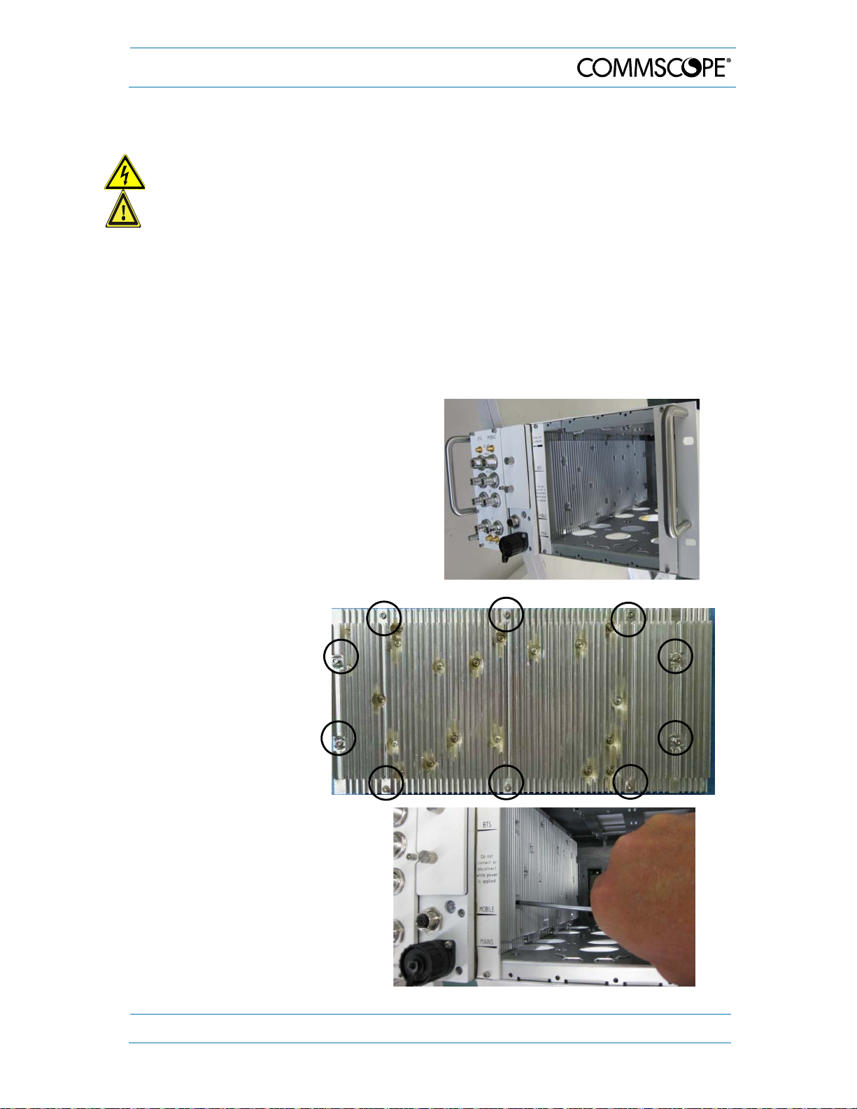
5. Maintenance
5.2.5. Power Supply
Danger: Electrical hazard. Danger of death or fatal injury from electrical current
inside the unit in operation. Before opening the unit, disconnect mains power.
Caution: Rotating fans. Risk of injury in operation. Wear tight-fitting clothes and
disconnect mains before working inside the unit.
Note: We strongly recommend not to replace a defect PSU on-site but to send the
Node AM to CommScope for repair. A replacement on-site must only be done
by a service technician of CommScope or by an equally trained person who
has the necessary qualifications to carry out such a replacement as well as the
corresponding safety tests demanded by local, regional and country-specific
regulations.
Note: Replacing a PSU with another type (e.g. 680 W with 780 W type) is not possible
on site.
To remove the original power supply
(AC/DC and DC/DC types are available),
proceed as follows:
Remove RF and dummy cards as
described in the next chapter 5.2.6.
We strongly recommend, to remove the
combiner as well (see chapter 5.2.1).
Positions of the ten
hexagon socket head
cap screws of the power
supply.
Unscrew the ten hexagon
socket head cap screws of the
power supply (positions as
shown above).
Note:
Do not unscrew any Torx
screw.
MF0121ACP_uc.docx Manual for Node AM4 Page 63
Page 64

Lift out the power supply
carefully with the lower part
first.
Disconnect the cables and
carefully lift the safety clips for
the disconnection.
1 mains cable (AC – or DC)
2 secondary cable (DC)
1)
2)
with safety clip
2
3 I
C bus cable 3)
snap-in clip / no safety clip
5. Maintenance
3
2
1
Metal-holder safety clip
1)
To disconnect the mains cable, observe the precautions illustrated on the next page.
2)
To disconnect cable, press metal-holder safety clip to the rear!
3)
Observe that the snap-in clip of I2C bus cable has to be pressed while loosening the
cable.
Page 64 MF0121ACP_uc.docx Manual for Node AM4
Page 65
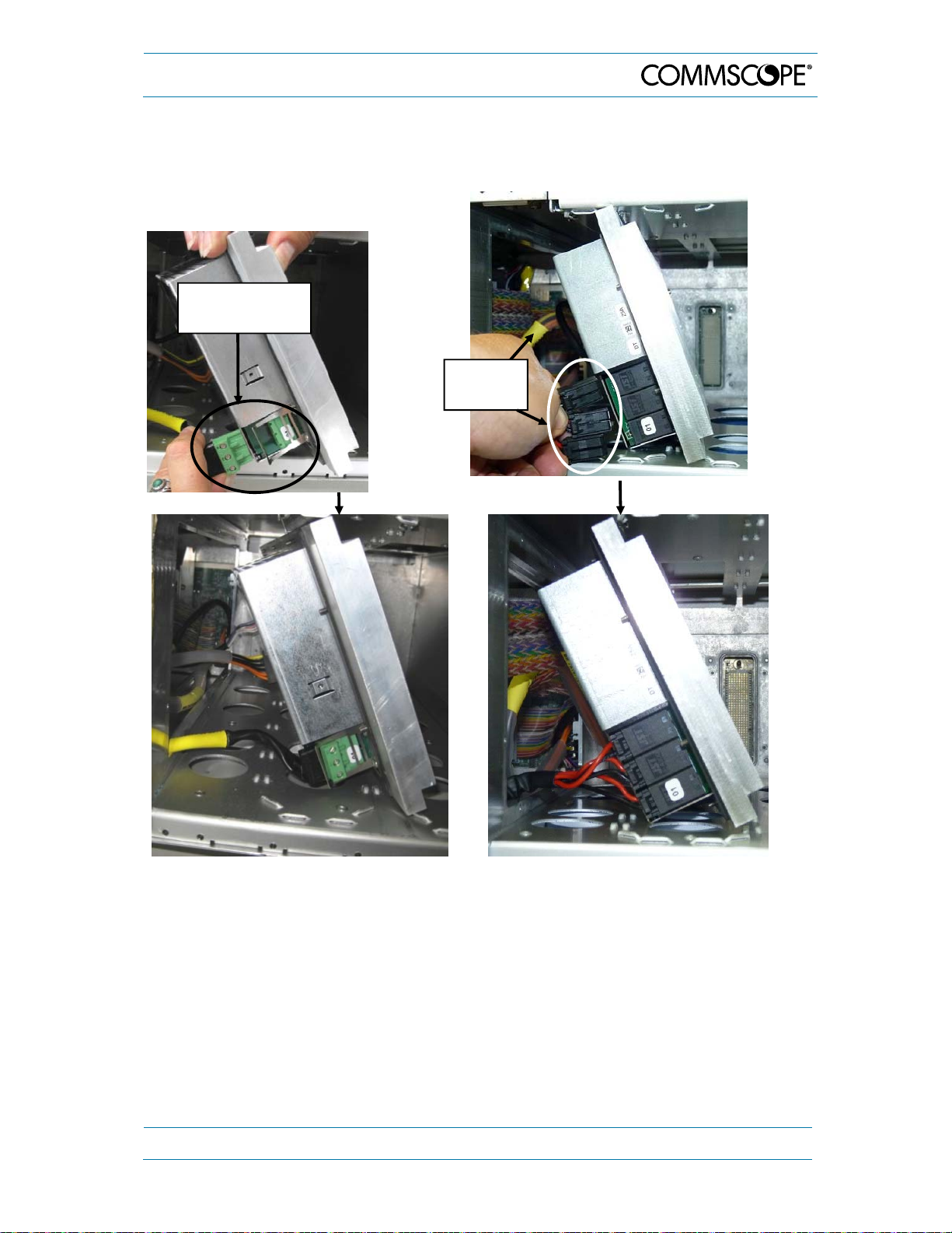
5. Maintenance
When disconnecting the mains cable from the power supply, observe the following:
In case of an AC/DC type,
carefully lift the safety clip for the
disconnection of the mains
cable:
Safety clip for
AC mains cable
In case of a DC/DC type, press the snap-in clip
for disconnection.
Mains
cable DC
When reconnecting the cables to the new power supply, observe the same precautions
as explained for the disconnection.
Observe that the cables have to be positioned as illustrated above to avoid damage by
squeezing, and make sure that no cables get disconnected by accident. Also, make sure
that no cables get in contact with the combiner and might be damaged or get
disconnected when the combiner is removed. After the procedure, carry out the
corresponding safety tests demanded by local, regional, and country-specific regulations
before mains is reconnected.
Then, fasten the power supply with the ten hexagon socket head cap screws.
Reinstall the RF and dummy cards and fasten all their screws tight to restore
watertightness.
MF0121ACP_uc.docx Manual for Node AM4 Page 65
Page 66

5. Maintenance
5.2.6. RF Card Exchange / Upgrade with Additional RF Cards
Caution: Rotating fans. Risk of injury in operation. Wear tight-fitting clothes and
disconnect mains before working inside the unit.
Notes:
This instruction is also valid for the slot duplexer.
It is strongly recommended to disconnect the Node AM from mains (power-
supply line) before an RF card is mounted or dismounted. In case the Node AM
is not allowed to be disconnected from mains, the RF card which needs to be replaced
must be disabled via software in the Technician page before removing it. This is to
avoid possible damage when inserting the new RF card.
Observe that the RF cards must always be packed separately for transport
All unused slots need to be assembled with a dummy card for sufficient airflow and
provided IP class.
Before upgrading or when replacing single-band with dual-band cards, observe the
limitations for the number of dual-band cards that may be equipped as specified in
chapter 7.1.
Replacing a single-band with a dual-band card impacts the share of available filters.
A total of 48 (backplane-controlled) filters can be defined at freely variable proportions
for all single-band cards equipped. For dual-band cards, these filters are not available
but each dual-band card provides additional 32 wide-band filters, which can be
variably shared among the two bands of this card only. Thus, if a single-band card for
which more than 32 filters were defined is replaced, these can no longer be provided
by the dual-band card.
This chapter shows the single-band cards but it is valid for dual-band cards as well.
To replace an RF card or to upgrade the Node AM with additional RF cards, proceed as
follows:
To remove an RF card / or dummy card (in case of an
upgrade):
Disconnect the cables.
Loosen the four socket head cap screws M3x16 mm)
and take the RF / dummy card out.
To install the RF card:
Use the guide rails on top and bottom to fit in the RF
card smoothly.
Note: Fasten the screws of the RF card tight to
restore watertightness. To do so, first, just slightly
tighten the screws crosswise in order to avoid cant, and
when all four screws are positioned correctly, fasten
them tight.
Use the guide rails on top and bottom to fit in the RF
card smoothly.
Reconnect the cables.
Page 66 MF0121ACP_uc.docx Manual for Node AM4
Page 67

5. Maintenance
Note: If an RF Card is exchanged by a card of another type, e.g. an AF2125 by an
AF1825/2125, resetting this card via the Technician Setup menu of the SW
(see SV manual) is recommended.
In case of an upgrade, also observe the following:
If the multiband combiner has to be upgraded as well (i.e. two-band combiner to three-
band combiner), refer to the instructions in chapter 5.2.1 for the exchange.
The required RF cables are part of the delivery of the RF card.
Connect the individual BTS band ports of the combiner to the BTS ports of the according
band of the RF cards.
Connect the individual Mobile band ports of the combiner to the Mobile ports of the
according band of the RF cards.
5.2.7. Fan Unit
5.2.7.1. Backside Type
For maintaining and cleaning instructions please refer to chapter 5.1 General.
Caution: Rotating fans. Risk of injury in operation. Wear tight-fitting clothes and
disconnect mains before connecting or replacing or cleaning the fan unit.
Unscrew the 14 x M3x6
countersunk Torx screws, 5 on
top, 5 at the bottom, 2 at each
side.
Carefully pull the complete fan
unit from the cabinet.
Unscrew the fan unit connector
and disconnect it.
To mount the new fan unit,
proceed in reverse order.
MF0121ACP_uc.docx Manual for Node AM4 Page 67
Page 68

5. Maintenance
5.2.7.2. Bottom Type
For maintaining and cleaning instructions please refer to chapter 5.1 General.
Caution: Rotating fans. Risk of injury in operation. Wear tight-fitting clothes and
disconnect mains before connecting or replacing or cleaning the fan unit.
Bottom side
Node AM4
Recommendation:
To access the fan tray,
carefully turn the Node
AM upside down.
Attention:
Ensure to remember the
Fan tray
exact position of the
cables connected! Do
NOT squeeze any cables.
Just loosen the 3 screws
(circle-marked) slightly at
the holding devices for
the fan tray and cable.
Holding devices
Page 68 MF0121ACP_uc.docx Manual for Node AM4
Page 69

5. Maintenance
Slid the unit in the
direction of the arrow
shown in the picture and
lift it.
Holding devices
Fan connector
Then you get access to
the fan cable to be
disconnected.
Carefully lift the fan tray to
be replaced.
To mount the new fan
unit, proceed as follows:
Fan tray
MF0121ACP_uc.docx Manual for Node AM4 Page 69
Page 70

Bring in the new fan tray
with the lugs along the
guides.
Insert it into the grooves
provided while moving
back the holding devices.
Attention:
Take care to properly
place the fan cables
again as before the
replacement. Do not
squeeze them.
Reconnect the fan cable
connectors and bring the
fan cable into position.
Tighten the holding
devices for fan tray and
cable again.
5. Maintenance
Lugs
Installation finished:
Page 70 MF0121ACP_uc.docx Manual for Node AM4
Page 71

6. Illustrations
6. Illustrations
6.1. Cabinet Drawings Node AM
6.2. Layout
figure 6-1 Cabinet of a Node AM4 (fan unit backside type)
figure 6-2 Layout of the Node AM4, example
MF0121ACP_uc.docx Manual for Node AM4 Page 71
Page 72

7. Specifications
7.1. Electrical Specifications
7.1.1. RF Card Options
7. Specifications
Modulation
Scheme
LTE 700
LTE 800**
LTE 850
GSM-R 900
GSM-R 900
EGSM 900
UMTS 900,
LTE900**
EGSM 900
UMTS 900,
LTE 900**
GSM 1800,
LTE 1800**
UMTS 2100,
LTE 2100**
LTE 2600**
***
***
RF Card
AF 7524 703 to 748 758to 803 80 27 24
AF 824
AF 835 90 27 35
AF 8524
AF 8535 90 27 35
AF 923 R
***
AF 936 R 90 25 36
***
,
AF 923 RE
,
AF 936 RE 90
,
AF 923
AF 936 90
AF 1823
AF 1835 92
AF 2125
AF 2135 92
AF 2625
AF 2635 92 27 35
UL Frequency,
MHz
832 to 862 791 to 821
824 to 849 869 to 894
876 to 880 921 to 925
876 to 915 921 to 960
880 to 915 925 to 960
1710 to 1785 1805 to 1880
1920 to 1980 2110 to 2170
2500 to 2570 2620 to 2690
DL Frequency,
MHz
Max. Gain,
dB
80 27 24
80 27 24
80 25 23
80
80
80
82
82 27 25
Uplink Composite
Output Power, dBm*
25 (GSM)
27 (UMTS, LTE)
25 (GSM)
27 (UMTS, LTE)
25 (GSM)
27 (UMTS, LTE)
25 (GSM)
27 (UMTS, LTE)
26 (GSM)
27 (LTE)
26 (GSM)
27 (LTE)
28 (UMTS)
27 (LTE)
28 (UMTS)
27 (LTE)
Downlink Composite
Output Power, dBm*
23 (GSM)
25 (UMTS, LTE)
36 (GSM, UMTS, LTE)
23 (GSM)
25 (UMTS, LTE)
36 (GSM, UMTS, LTE)
23 (GSM)
25 (LTE)
35 (GSM, LTE)
25 (UMTS, LTE)
35 (UMTS, LTE)
* Output power per carrier (dBm) = composite output power (dBm) - 10 x log (no. of carriers)
** LTE and UMTS uplink composite output power (dBm) valid for sub-bands ≤ 10 MHz, slight reduction of output power for sub-
bands > 10 MHz only”]
*** Downlink output power @ 2 carriers for AF936, AF936R, AF936RE: 30 dBm/carrier
table 7-1 RF card options, EMEA, single band cards
Page 72 MF0121ACP_uc.docx Manual for Node AM4
Page 73
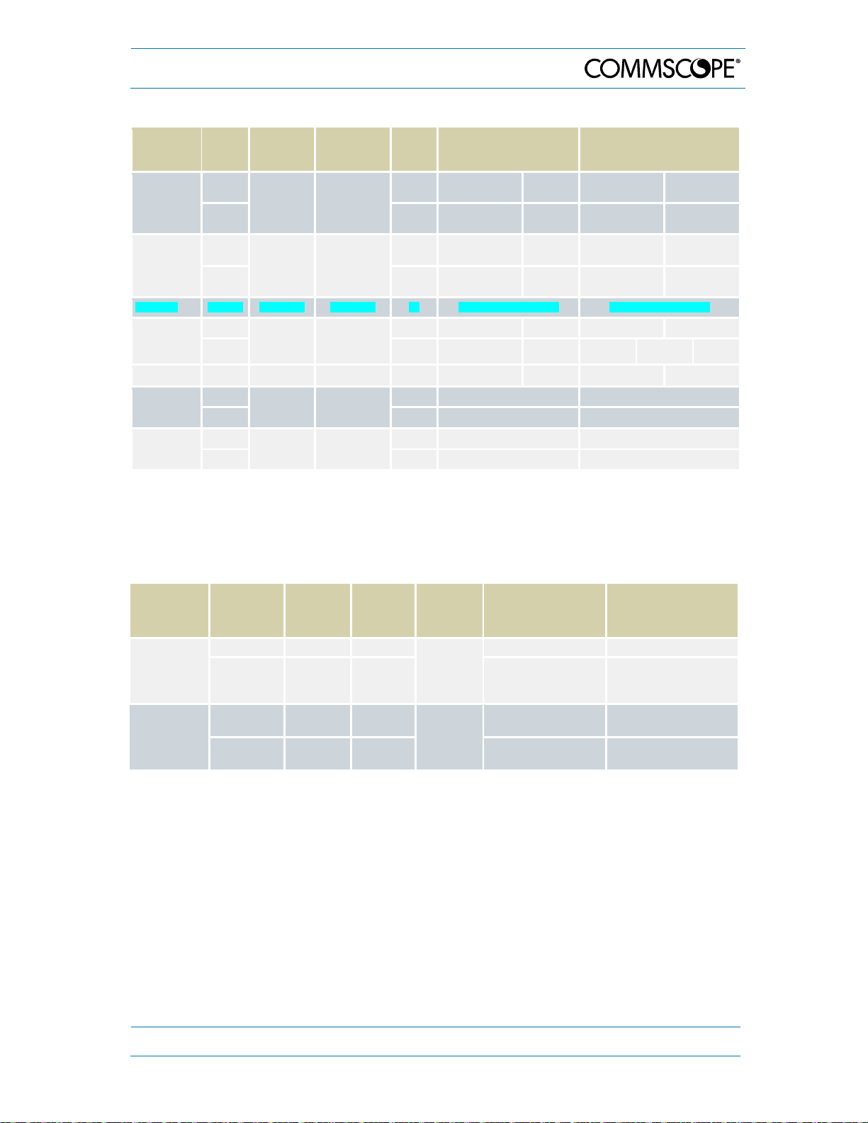
7. Specifications
Modulation
Scheme
CELL 700,
UMTS 700,
LTE 700
CELL 850,
UMTS 850,
LTE 850
CELL 900 AF 9037 896 to 902 935 to 941 94 30 (GSM, CDMA, IDEN) 37 (GSM, CDMA, IDEN)
CDMA 1700 3),
UMTS 1700 3),
LTE 1700 3)
LTE 1700 3)
GSM 1900
CDMA 1900,
LTE 1900
LTE 2600 2)
1)
Output power per carrier (dBm) = composite output power (dBm) - 10 x log (no. of carriers)
2)
LTE uplink composite output power (dBm) valid for sub-bands ≤ 10 MHz
3)
To fulfill the FCC the UL requirement of 1 Watt EIRP max. for the AWS uplink band, the type of donor antenna
RF Card
AF 727
AF 737 94
AF 8527
AF 8537 94
AF 1727
AF 1737 94 30 (CDMA, LTE) 28 (UMTS) 37 (CDMA) 35 (UMTS) 36 (LTE)
AF1727E 1710 to 1780 2110 to 2180 84 30 (CDMA, LTE) 28 (UMTS) 27 (CDMA, LTE) 25 (UMTS)
AF 1927
AF 1937 94 30 (GSM, CDMA, LTE) 37 (GSM, CDMA, LTE)
AF 2625
AF 2635 92 27 35
UL
Frequency,
MHz
698 to 716
and
776 to 787
824 to 849 869 to 894
1710 to 1755 2110 to 2155
1850 to 1915 1930 to 1995
2500 to 2570 2620 to 2690
must be selected in a way not to exceed the 1 Watt. EIRP. Antenna type selection and execution of installation
has to be done in accordance to the relevant FCC part and is in responsibility of the installer.
DL
Frequency,
MHz
728 to 757
Max.
Gain,
Uplink Composite Output
dB
84
84
84 30 (CDMA, LTE) 28 (UMTS) 27 (CDMA, LTE) 25 (UMTS)
84 30 (GSM, CDMA, LTE) 27 (GSM, CDMA, LTE)
82 27 25
Power, dBm 1)
30 (GSM, CDMA,
IDEN, LTE)
30 (GSM, CDMA,
IDEN, LTE)
30 (GSM, CDMA,
IDEN, LTE
30 (GSM, CDMA,
IDEN, LTE)
28 (UMTS)
28 (UMTS)
28 (UMTS)
28 UMTS
Downlink Composite Output
Power, dBm 1)
27 (GSM, CDMA,
IDEN, LTE)
37 (GSM, CDMA,
IDEN, LTE)
27 (GSM, CDMA,
IDEN, LTE)
37 (GSM, CDMA,
IDEN, LTE)
25 (UMTS)
35 (UMTS)
25 (UMTS)
35 (UMTS)
table 7-2 RF card options for USA, single band cards
RF Card
Modulation
Scheme
UL
Frequency,
MHz
DL
Frequency,
MHz
Max. Gain,
dB
Uplink Composite
Output Power, dBm*
Downlink Composite
Output Power, dBm*
AF824/923
(combined
antenna ports)
AF 1823/2125
(combined
antenna ports)
LTE 800 832 to 862 791 to 821
EGSM 900,
UMTS 900,
LTE 900
GSM 1800,
LTE 1800
UMTS 2100,
LTE 2100
880 to 915 925 to 960
1710 to 1785 1805 to 1880
1920 to 1980 2110 to 2170
70
72
27 25
24 (GSM)
27 (UMTS, LTE)
26 (GSM)
27 (LTE)
27 (UMTS, LTE) 25 (UMTS, LTE)
22 (GSM)
25 (UMTS, LTE)
23 (GSM)
25 (LTE)
* Output power per carrier (dBm) = composite output power (dBm) - 10 x log (no. of carriers)
table 7-3 RF card options, dual band cards
MF0121ACP_uc.docx Manual for Node AM4 Page 73
Page 74
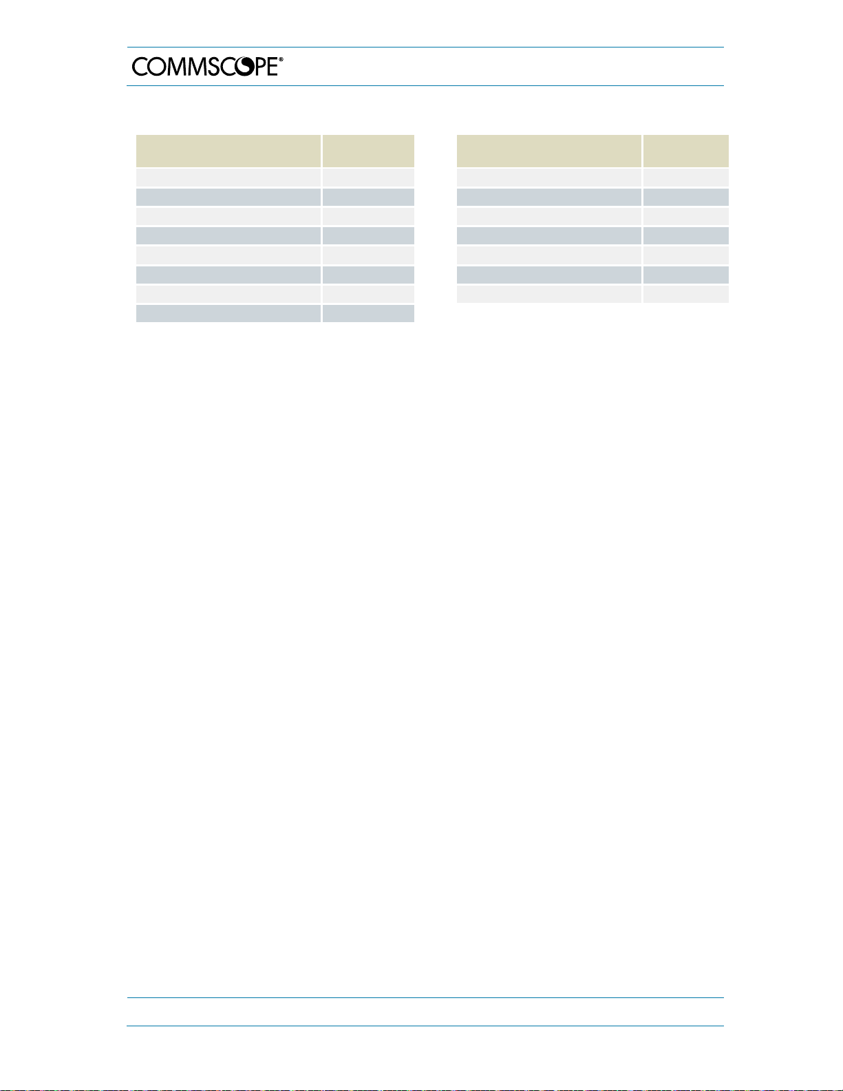
7. Specifications
7.1.2. Bandwidths available in UL and DL per rack (single-band cards)
Sub-Band Bandwidth [MHz] Filter
Resources
0.01 to 5.00 1
5.01 to 10.00 2
10.01 to 15.00 3
15.01 to 20.00 4
20.01 to 25.00 5
25.01 to 30.00 6
30.01 to 35.00 7
35.01 to 40.00 8
Sub-Band Bandwidth [MHz] Filter
40.01 to 45.00 9
45.01 to 50.00 10
50.01 to 55.00 11
55.01 to 60.00 12
60.01 to 65.00 13
65.01 to 70.00 14
70.01 to 75.00 15
Resources
table 7-4 Bandwidths available in UL and DL per rack, single-band cards
All data is subject to change without notice.
Detailed System Description – Single-Band Cards
Node AM RF cards convert the RF into digital signals and transfer them to the Node AM
rack for digital filtering. The digital architecture allows sub-band filtering and is shared
between all RF Cards inserted into the Node AM rack. The Node AM4 can provide up to
48 filter resources (up to 5 MHz each). Additional filtering capability is provided by on-
card digital signal processing at dual-band RF cards to satisfy increasing demand of subbands for further RF-bands or MIMO deployments. When the sub-band bandwidths are
greater than 5 MHz, the filter resources are grouped together, without phase or amplitude
ripple, where the sub-band is defined by a start and stop frequency. The total number of
used filter resources is determined by adding the number of filter resources required for
each sub-band.
For example, if there are three sub-bands with 4 MHz for the first sub-band, 11 MHz for
the second sub-band, and 20 MHz for the third sub-band, then 1 filter resource is required
for the first sub-band, 3 filter resources are required for the second sub-band and 4 filter
resources are required for the third sub-band. The total number of used filter resources
in this example is 8. However, the maximum available bandwidth (240 MHz) will only be
achieved with sub-band bandwidths of integer multiple of 5 MHz.
The following diagram shows examples for filter resources allocation:
Page 74 MF0121ACP_uc.docx Manual for Node AM4
Page 75

7. Specifications
]
Example of filter resources allocation (up to 5 MHz wide) of Node AM4 rack (singleband cards):
1
48
25
24
23
2
3
4
5
6
7
8
9
10
11
12
13
14
15
16
17
18
19
20
21
22
47
46
45
44
43
42
41
40
39
38
37
36
35
34
33
32
31
30
29
28
27
26
∆
Operator A GSM 900 1 Band 6 MHz
∆
Operator A GSM 1800 1 Band 32 MHz
∆
Operator A UMTS 2100 1 Band 20 MHz
∆
Operator B GSM 900 1 Band 14 MHz
∆
Operator B GSM 1800 1 Band 23 MHz
∆
Operator B UMTS 2100 1 Band 20 MHz
∆
Operator C GSM 900 1 Band 15 MHz
∆
Operator C GSM 1800 1 Band 20 MHz
∆
Operator C UMTS 2100 1 Band 20 MHz
∆
Unused filter resources: 12
table 7-5 Filter resources allocation (up to 5 MHz wide), example
All data is subject to change without notice.
7.1.3. Bandwidths available in UL and DL per dual-band card
Sub-Band Bandwidth
[MHz
0.01 to 5.00 1 40.01 to 45.00 9
5.01 to 10.00 2 45.01 to 50.00 10
10.01 to 15.00 3 50.01 to 55.00 11
15.01 to 20.00 4 55.01 to 60.00 12
20.01 to 25.00 5 60.01 to 65.00 13
25.01 to 30.00 6 65.01 to 70.00 14
30.01 to 35.00 7 70.01 to 75.00 15
35.01 to 40.00 8
table 7-6 Bandwidths available in UL and DL per dual- band card
All data is subject to change without notice.
MF0121ACP_uc.docx Manual for Node AM4 Page 75
Filter
Resources
Sub-Band Bandwidth
[MHz]
Filter
Resources
Page 76
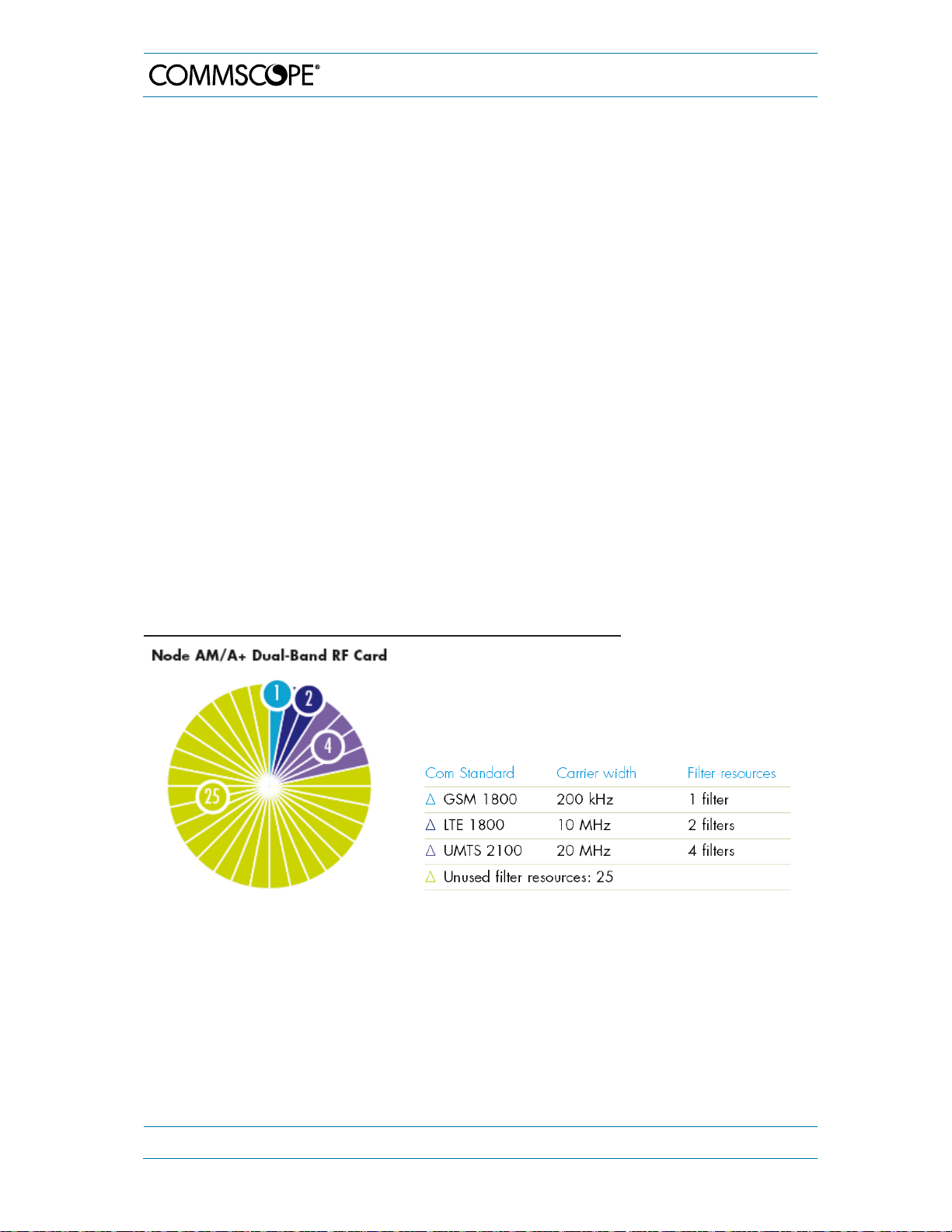
Detailed System Description – Dual-Band Cards
With the increasing demand for mobile communication, additional radio frequency (RF)
bands are globally assigned to meet that demand. In addition, better utilization of the
radio spectrum is being addressed by Multiple-In Multiple-Out (MIMO) antenna
technology and techniques. However, basically all measures to increase the
communication link capacity result in an increased number of parallel operated radio front
ends. In response to this trend, CommScope has enhanced the radio band capacity of its
existing Node AM platform by providing Dual Band RF cards. Following a software
upgrade, two medium power RF front ends can be operated in the same space of a legacy
single band plug-in module.
Thanks to the on-card digital signal processing functionality, up to 32 filter resources (0.2
… 5 MHz each) are available per dual card. Depending on the upgrade goal, i.e.
increasing the number of RF bands or MIMO performance, dual band RF cards for interband, e.g. 8/9 or 18/21, combination are available.
When using CommScope’s Node AM chassis in situations where the sub-band
bandwidths are greater than 5 MHz and where the sub-bands are defined by a start and
stop frequency, the filter resources are grouped together, without phase or amplitude
ripple. The total number of used filter resources per dual band card is determined by
adding the number of filter resources required for each sub-band in both RF bands
together. For example, if there are three sub-bands with 200 kHz for the first sub-band
and 10 MHz for the second sub-band in the 1800 MHz band and 20 MHz for the third subband in the 2100 MHz band then one filter resource is needed in the first, two in the
second, and four in the third sub-band. The total number of filter resources used is seven.
7. Specifications
Example of filter resources allocation (up to 5 MHz wide):
table 7-7 Filter resources allocation (up to 5 MHz wide), example
Page 76 MF0121ACP_uc.docx Manual for Node AM4
Page 77
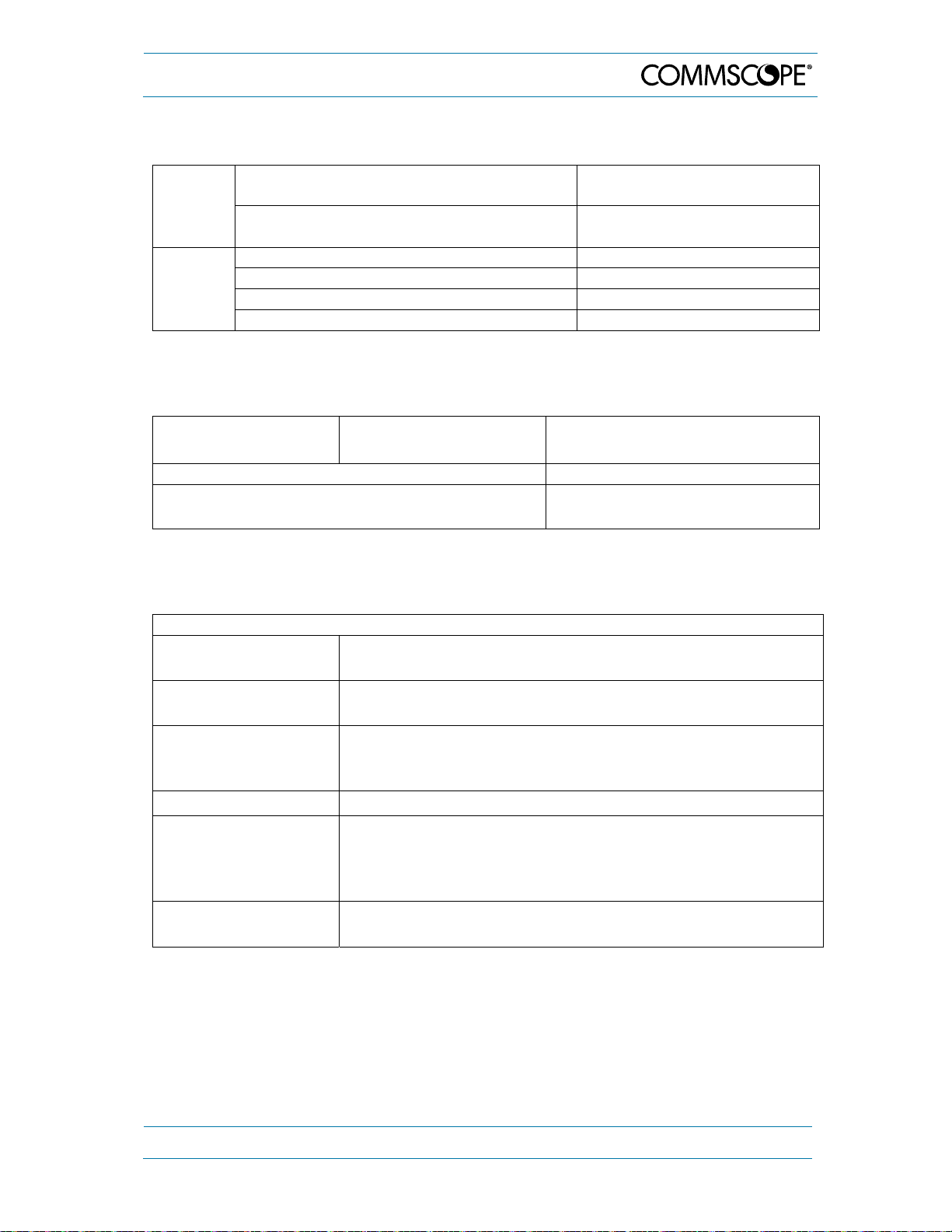
7. Specifications
(
g
7.2. Mechanical Specifications
Height,
width,
depth
Weight
Node AM4 chassis (with fan at backside)
Node AM4 chassis (with fan at bottom)
Node AM4 chassis 14 kg (30.8 lb)
RF card AX23 - AX25 3 kg (6.5 lb)
RF card AX35 - AX36 4.5 kg (10 lb)
Dual band RF card 6 kg (13.2 lb)
All data is subject to change without notice.
177.0 x 482.3 x 462.8 mm
7 x 19 x 18.2 in)
177.0 x 482.3 x 436.3 mm
(7 x 19 x 17.2 in)
7.3. Environmental and Safety Specification
Operating
temperature range
Ingress protection IP65 (Fans: IP55)
Acoustic noise (fan unit backside type)
RF card Ax23 - Ax25
RF card Ax35 - Ax36
All data is subject to change without notice.
-33°C to +55°C
-33°C to +50°C
47 dB(A) @ 25°C
55 dB(A) @ 50°C
7.4. Features
Features
Statistic collection
Gain trailing
Access
External alarms Up to 5 alarms, active high or low configurable via software.
GPS functionality
Battery Backup Battery backup to supply modem and controller for alarming
Collecting data (min., max., average, standard deviation) of
items measured in a 15 minutes interval.
Gain adjustment based on DL RSSI. UL gain is automatically
set correspondin
Web browser based local access and remote access. Packet
data and circuit switched data options. OMC connectivity via
SNMP.
Modem with a built-in GPS receiver for fast and easy location
detection available as an option. Based on received GPS
position the Node AM automatically changes the RF alarm
and/or connectivity configuration.
of mains power failure.
to DL gain.
All data is subject to change without notice.
For detailed description of the features above, please refer to the software manual which
is part of the Node AM4 delivery.
MF0121ACP_uc.docx Manual for Node AM4 Page 77
Page 78
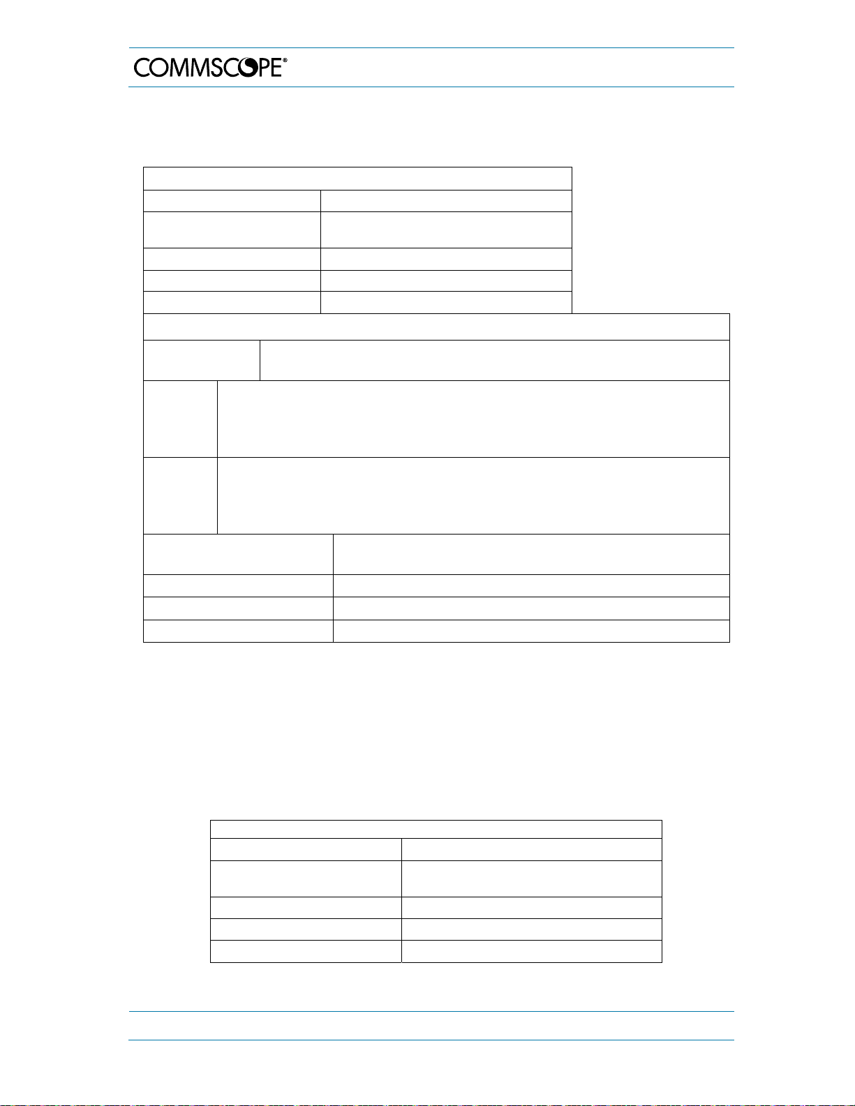
7. Specifications
7.5. Modems
7.5.1. HC25 / PHS8 / PLS8 / MC88 / TRM-5
MC Technologies MC88 / TRM-5
Service GSM/GPRS
Service connection
Physical connection RS232, 6PG Molex, FME
Power consumption 4 W
Connectors Data, power, RF
MC Technologies HC251) / PHS81) / PLS8-EU / PLS8-US
Circuit switch
Packet switch
Service HC25 /
PHS8
GSM/GPRS/EDGE/UMTS HSPA2)
GPS
LTE: 800/900/1800/2600 MHz, FDD-Band (20,8,3,7)
Service
PLS8EU
UMTS (WCDMA): 900/1800/2100 MHz, FDD-Band (8,3,1)
GSM/GPRS/EDGE: 900/1800 MHz
GPS
LTE: 700/850/AWS(1700/2100)/1900 MHz, FDD-Band (17,5,4,2)
Service
PLS8US
UMTS (WCDMA): 850/AWS(1700/2100)/1900 MHz, FDD-Band (5,4,2)
GSM/GRPS/EDGE: 850/900/1800/1900 MHz
GPS
Service connection
Circuit switched data (not available for PLS8)
Packet switched data
Physical connection USB, RS2323), 6PG Molex, FME
Power consumption 4 W
Connectors Data, power, RF
1)
Modem PHS8 is replacing Modem HC25, which is discontinued (both are identical except the fact that
the RS232 connector must not be used with the PHS8 type).
2)
HSPA is for PHS8 only
3)
The RS232 connector must not be used with the PHS8 and PLS8 types.
Note: The HC25 / PHS8 and MC88 modems are similar. For TRM-5 and MC 88
modems, please make sure that the serial port baud rate is set to the appropriate
value. Please refer to the Node AM/ Node A+ Software Manual for more details.
7.5.2. Wireless Router M!DGE (Racom)
M!DGE *
Service LTE/HSPA/UMTS/EDGE/GPRS
Service connection
Circuit switch
Packet switch
Physical connection RS232, 2x Ethernet, USB, SMA
Power consumption 5 W
Connectors Data, power, RF
* M!DGE Wireless Router supported by software, mounting kit incl. cables available;
M!DGE router must be purchased directly at Racom or any distributors.
Page 78 MF0121ACP_uc.docx Manual for Node AM4
Page 79
8. Spare Parts List
A
)
(
)
)
)
)
(
)
)
(
)
)
)
)
)
(
)
)
)
)
)
8. Spare Parts List
The following list contains all FRUs available for the Node AM4. The Node AM4
configuration is available in the web interface.
Designation ID No
Node AM4 7613589
dapter Kit Modem Node AM
Combiner Kit 8-9/18/21 GPS, VSWR 7617865
Combiner Kit 8/9/18/21 GPS, VSWR
Combiner Kit 8/9/18-21/26 GPS, VSWR
Combiner Kit 8-9/18/21/26 GPS, VSWR
Combiner Kit 7/8-9/18-21/26 GPS, VSWR
Combiner Kit 7/85/17E/19 7817692
Cover (for transport protection
DCM AF 7524
DCM AF 7524L (703-733 / 758-788 MHz
DCM AF 824 (832 –862 / 791 –821 MHz
DCM AF 824 (832 –862 / 791 –821 MHz
DCM AF 824/923 combined ports
832 to 862/791 to 821 MHz & 880 to 915/925 to 960 MHz)
DCM AF 835 (832 –862 / 791 –821 MHz
DCM AF 923 R (876 - 880 / 921 - 925 MHz
DCM AF 936 R (876 - 880 / 921 - 925 MHz) 7606746-01
DCM AF 923 RE 2) (876 to 915/921 to 960 MHz)
DCM
Commercial
Applications
(EMEA)
requires Slot Duplexer 7621867-00
DCM AF 936 RE (876 to 915/921 to 960 MHz)
(requires Slot Duplexer 7621867-00)
DCM AF 923 (880 - 915 / 925 - 960 MHz) 7562492-01
DCM AF 923 (880 - 915 / 925 - 960 MHz
DCM AF 936 (880 - 915 / 925 - 960 MHz
DCM AF 1823 (1710 - 1725 / 1805 - 1880 MHz
DCM AF 1823 (1710 - 1725 / 1805 - 1880 MHz
DCM AF 1823/2125 combined ports
1710 to 1785/1805 to 1880 MHz
DCM AF 1835 (1710 - 1725 / 1805 - 1880 MHz
DCM AF 2125 (1920 - 1980 / 2110 - 2170 MHz
DCM AF 2125 (1920 - 1980 / 2110 - 2170 MHz
DCM AF 2135 (1920 - 1980 / 2110 - 2170 MHz
DCM AF 2625 (2500 - 2570 / 2620 - 2690 MHz) 7621749-01
DCM AF 2635 (2500 - 2570 / 2620 - 2690 MHz) 7621747-01
1)
To avoid a collision between modem connectors and combiner, the adapter kit 7817687 for modem
installation (see figure 5-1) is used. If it is not yet installed, order it together with the new combiner.
2)
Railway approved cables
1)
1)
1)
1)
1)
703-748 / 758-803 MHz
7817687
7635384
7697443
7697689
7703442
7703683-00
7761303-00
7761306-00
2)
7661357-01
7621773-01
7693191-00
7621771-01
7606744-01
7621746-01
7625530-01
2)
7630563-01
7562493-01
7562494-01
2)
7630565-01
7700741-00
7562495-01
7562496-01
2)
7626358-01
7562497-01
MF0121ACP_uc.docx Manual for Node AM4 Page 79
Page 80

)
)
)
)
8. Spare Parts List
Designation ID No
Node AM4 7613589
DCM AF 727 (698 to 716 & 776 to 787 / 728 to 757 MHz) 7577532-01
DCM AF 737 (698 to 716 & 776 to 787 / 728 to 757 MHz) 7598983-01
DCM
Commercial
Applications
(US)
DCM AF 8527 (824 - 849 / 869 - 894 MHz) 7577540-01
DCM AF 8537 (824 - 849 / 869 - 894 MHz) 7577542-01
DCM AF 1727 (1710 - 1755 / 2110 - 2155 MHz) 7577548-01
DCM AF 1727E (1710 to 1780 / 2110 to 2180 MHz) 7817693-00
DCM AF 1737 (1710 - 1755 / 2110 - 2155 MHz
DCM AF 1927 (1850 - 1915 / 1930 - 1995 MHz
DCM AF 1937 (1850 - 1915 / 1930 - 1995 MHz
DCM AF 9037 (UL 896 - 902 MHz / DL 935 - 941 MHz
7577550-01
7577552-01
7577554-01
7577546-01
DCM AF 8524 (AUS) 7801322-00
Dummy card 7574285-00
Dummy card T5 7643315-00
Fan Unit Backside Type (Kit) 7574286
Fain Unit Bottom 7644217-00
GPS Bias-T cable (AC/DC Cable USB 0.4 M Molex. 3 pol) 7626927-00
Modem-Kit PHS8 Node AM 3) 7679538
Modem-Kit PLS-8 Node AM EU 7724196-00
Power Supply Unit DC IN 24-110 V 680 W 7609268-00
Power Supply Unit DC IN 24-110V 780W 7711908-xx
Power Supply Unit AC IN 100-240 V 680 W 7605769-00
Rechargeable battery pack 6 V 7613775-00
Slot Duplexer passive (876-915/921-960 MHz) 7621867-00
User Interface 2 - Kit > V2.0.6 4) 7814162
User's Manuals for Node AM4 7617868-00
VSWR Kit 925-960 MHz 7622883
VSWR-Module 925-960 MHz 7614218-00
3)
Modem-Kit PHS8 is the successor of Modem-Kit HC25 which has been discontinued
4)
Due to a PCB update on the UI2 Board (see also chapter 4.3.6), SW version V2.0.6 is mandatory for
this kit (containing UI2 Board 7613646-05). The former User Interface 2 – Kit 7622884 (containing UI2
Board 7613646-03) is no longer available. The UI2 Board cannot be ordered separately
The manufacturer reserves the right to replace the parts listed above by equivalent
substitutes.
Note: To ensure compatibility with your system, do not order any individual
components (e.g. modems) of the kits available. Make sure to always order
the complete kit (ID must be listed above) as spare part.
Page 80 MF0121ACP_uc.docx Manual for Node AM4
Page 81

9. Index
9. Index
A
Abbreviations............................................................ 7
AC Breaker ............................................................. 32
Alarm Forwarding ................................................... 36
Alarms, External ..................................................... 42
B
Battery Backup - Option ......................................... 46
Battery Backup - Safety Warnings ................... 47, 57
Battery Replacement.............................................. 57
BBH ........................................................................ 35
C
Cabinet Drawings ................................................... 71
CE Declaration of Conformity (DoC) ...................... 14
Cleaning, Fan Unit ................................................. 52
CommScope ........................................................... 14
Compliance .............................................................. 9
Connection from Laptop or PC .............................. 33
Connections
Antenna ............................................................. 25
Power ................................................................ 31
Contact Addresses, Customer Support ........... 15, 16
D
DC Breaker ............................................................. 32
DCM ....................................................................... 39
Declaration of Conformity (DoC) ............................ 14
Digital Channel Modules ........................................ 39
Dummy Card .......................................................... 40
E
External Alarms ...................................................... 42
F
Fan Unit .................................................................. 52
Replacement ..................................................... 67
Filters
Standard Feature .............................................. 34
Types ................................................................. 35
Frequency Hopping ................................................ 35
G
Gain ........................................................................ 35
Grounding (Earthing).............................................. 24
H
Health and Safety ..................................................... 8
I
Installation
Electrical ............................................................ 23
Mechanical ........................................................ 19
Interconnection Cabling ......................................... 25
L
Layout Node AM4 .................................................. 71
Layout, Components ............................................. 36
LED Kit ................................................................... 62
Local Connection ................................................... 33
M
Mains Power Interruption ....................................... 32
Modems ................................................................. 48
Initstrings ........................................................... 48
Specifications .................................................... 78
Mounting ................................................................ 20
Multiband Combiner .............................................. 38
Replacement ..................................................... 55
P
Parts List ................................................................ 79
Power Supply Unit ................................................. 40
Replacement ..................................................... 63
Property Damage Warnings .................................... 8
R
Relay Contacts ...................................................... 44
Replacement of
Battery ............................................................... 57
Components ...................................................... 52
Fan Unit ............................................................ 67
Multiband Combiner .......................................... 55
Power Supply .................................................... 63
Slot Duplexer .................................................... 66
VSWR Module .................................................. 61
RF Cards ................................................................ 39
Packing ............................................................. 52
Replacement, Upgrade ..................................... 66
Upgrade ............................................................ 67
Router Specifications ............................................. 78
RSSI ....................................................................... 35
S
SFH ........................................................................ 35
SIM Card ................................................................ 50
Slot Duplexer ................................................... 36, 39
Replacement ..................................................... 66
SMS Alarm Forwarding ......................................... 36
Specifications
Environmental and Safety ................................ 77
Features ............................................................ 77
HC25/PHS8/PLS8 ............................................ 78
M!DGE Router .................................................. 78
Mechanical ........................................................ 77
Modems ............................................................ 78
RF Card Options (Commercial) ........................ 73
Status Information.................................................. 35
Status LED ............................................................. 62
Summary Alarm ..................................................... 44
T
Transport Protection Cover ................................... 20
MF0121ACP_uc.docx Manual for Node AM4 Page 81
Page 82
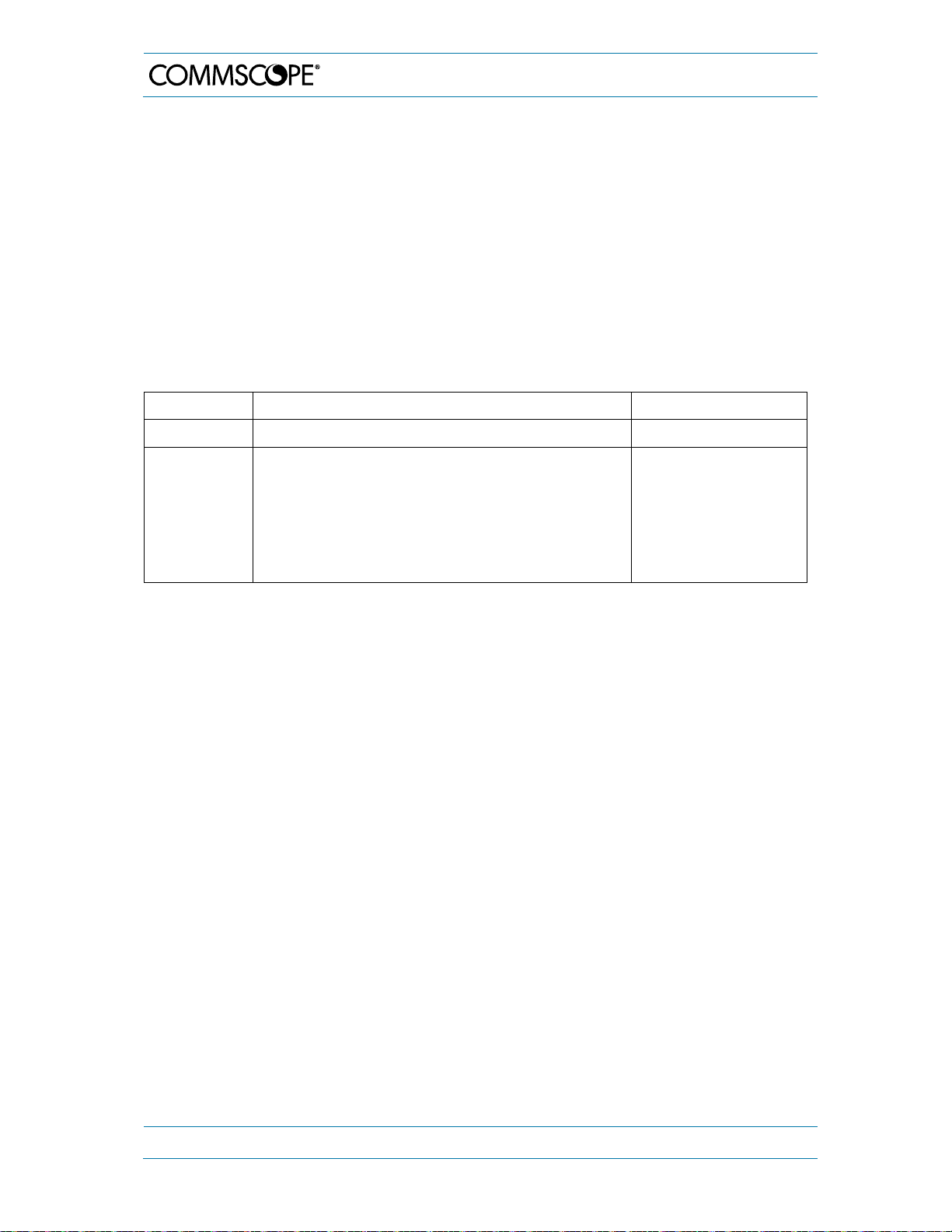
g
A
U
UI2 Board ............................................................... 46
Upgrade
Additional RF cards ........................................... 66
RF Cards ........................................................... 67
User Interface 2 ...................................................... 46
10. List of Changes
Version Chan
es Release Date
10. List of Changes
V
VSWR Module
Option ................................................................ 61
Replacement ..................................................... 61
VSWR Module - Option ......................................... 46
W
Watertightness ....................................................... 54
M0121ACN 18M0121ACP - Chapters 1.1 and 1.4 updated (AWS, WEEE)
- Chapters 4.3.6, 5.2.1, and 5.2.2 updated due
to new modem mounting plate
- RF card options for US added (table 7-2)
- Chapter 8 updated.
pril-2018
30-August-2018
Page 82 MF0121ACP_uc.docx Manual for Node AM4
Page 83

 Loading...