

Page 1
24987-A
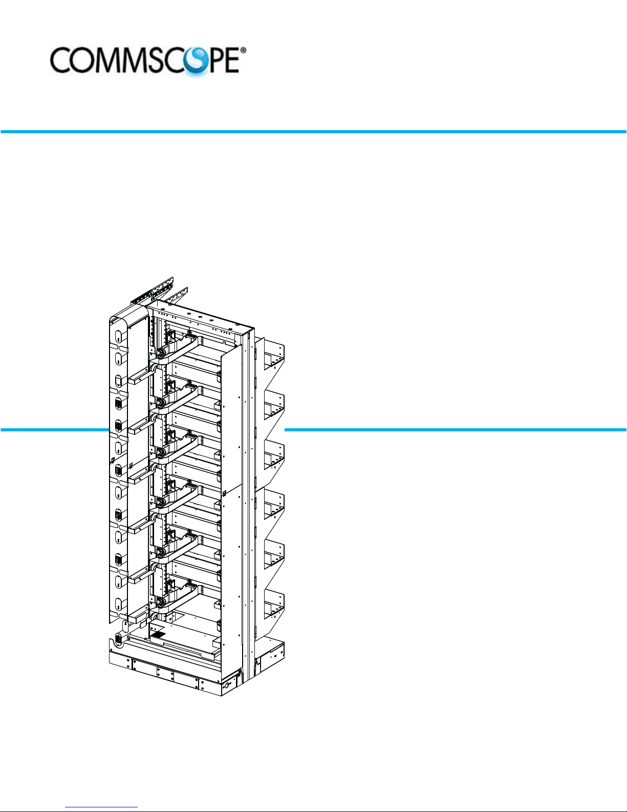
NG4access® Frame
Installation Manual (Raised Floor)
TECP-90-708
Issue 5, April 2017
300001764826 Rev B
www.commscope.com
Page 2

TECP-90-708 • Issue 5 • April 2017 • Preface
COPYRIGHT
© 2016, CommScope Inc.
All Rights Reserved
REVISION HISTORY
ISSUE DATE REASON FOR CHANGE
1 9/2012 Original.
2 12/2012 Added instructions for installing Raised Floor Cable Clamp Bracket Kit.
3 7/2013 Added instructions for installing the Fiber Optic Storage Panel (FOTSP) and the Auxiliary Cable Spool
4 July 2016 Reformatted for CommScope.
5 April 2017 Corrected Material ID on cover.
TRADEMARK INFORMATION
CommScope and CommScope (logo), and NG4access are trademarks.
Telcordia is a registered trademark of Telcordia Technologies, Inc.
GORE is a registered trademark of W. L. Gore & Associates, Inc.
Bracket Kit.
DISCLAIMER OF LIABILITY
Contents herein are current as of the date of publication. CommScope reserves the right to change the contents without prior notice.
In no event shall CommScope be liable for any damages resulting from loss of data, loss of use, or loss of profits and
CommScope further disclaims any and all liability for indirect, incidental, special, consequential or other similar damages.
This disclaimer of liability applies to all products, publications and services during and after the warranty period.
This publication may be verified at any time by contacting CommScope’s Technical Assistance Center at:
http://www.commscope.com/SupportCenter
Page ii
Page 3

TABLE OF CONTENTS
Content Page
About This Manual . . . . . . . . . . . . . . . . . . . . . . . . . . . . . . . . . . . . . . . . . . . . . . . . . . . . . . . . . . . . . . . . . . . . . . . . . . . v
Related Publications . . . . . . . . . . . . . . . . . . . . . . . . . . . . . . . . . . . . . . . . . . . . . . . . . . . . . . . . . . . . . . . . . . . . . . . . . . v
Admonishments . . . . . . . . . . . . . . . . . . . . . . . . . . . . . . . . . . . . . . . . . . . . . . . . . . . . . . . . . . . . . . . . . . . . . . . . . . . . .vi
General Safety Precautions . . . . . . . . . . . . . . . . . . . . . . . . . . . . . . . . . . . . . . . . . . . . . . . . . . . . . . . . . . . . . . . . . . . . .vi
List of Acronyms and Abbreviations . . . . . . . . . . . . . . . . . . . . . . . . . . . . . . . . . . . . . . . . . . . . . . . . . . . . . . . . . . . . . . . .vi
1 TOOLS AND MATERIALS REQUIRED. . . . . . . . . . . . . . . . . . . . . . . . . . . . . . . . . . . . . . . . . . . . . . . . . . . . . . . . . . . 1
2 FOOTPRINT OF FRAME AND FIBER OPTIC STORAGE PANEL (FOTSP) . . . . . . . . . . . . . . . . . . . . . . . . . . . . . . . . . . . . 6
3 MOUNTING THE FRAME ON A RAISED FLOOR . . . . . . . . . . . . . . . . . . . . . . . . . . . . . . . . . . . . . . . . . . . . . . . . . . . . 7
4 INSTALLING A FIBER OPTIC STORAGE PANEL (FOTSP). . . . . . . . . . . . . . . . . . . . . . . . . . . . . . . . . . . . . . . . . . . . . 30
5 INSTALLING A RAISED FLOOR CABLE BRACKET . . . . . . . . . . . . . . . . . . . . . . . . . . . . . . . . . . . . . . . . . . . . . . . . . 35
6 INSTALLING A SPOOL BRACKET ASSEMBLY (FOR FRAME WITH SPLICE CHASSIS). . . . . . . . . . . . . . . . . . . . . . . . . . 44
7 INSTALLING AUXILIARY CABLE SPOOLS (FOR FRAMES WITHOUT SPLICE CHASSIS) . . . . . . . . . . . . . . . . . . . . . . . . 46
8 GROUNDING THE FRAME . . . . . . . . . . . . . . . . . . . . . . . . . . . . . . . . . . . . . . . . . . . . . . . . . . . . . . . . . . . . . . . . . 48
9 SECURING TWO FRAMES TOGETHER. . . . . . . . . . . . . . . . . . . . . . . . . . . . . . . . . . . . . . . . . . . . . . . . . . . . . . . . . 49
10 CUSTOMER INFORMATION AND ASSISTANCE . . . . . . . . . . . . . . . . . . . . . . . . . . . . . . . . . . . . . . . . . . . . . . . . . . . 52
TECP-90-708 • Issue 5 • April 2017 • Preface
© 2017, CommScope, Inc.
Page iii
Page 4

TECP-90-708 • Issue 5 • April 2017 • Preface
TABLE OF CONTENTS
Content Page
Blank
Page iv
© 2017, CommScope, Inc.
Page 5

ABOUT THIS MANUAL
This manual provides complete instructions for installing a NG4access frame on a raised floor.
Included are instructions for grounding the frame and joining two frames in a lineup.
RELATED PUBLICATIONS
Listed below are related manuals and their publication numbers. Copies of these publications
can be ordered by contacting the CommScope Technical Assistance Center at:
http://www.commscope.com/SupportCenter
Title/Description Publication Number
NG4access ODF Platform Application and Planning Manual 90-701
Contains an NG4access overview and information for planning a NG4access
application.
TECP-90-708 • Issue 5 • April 2017 • Preface
NG4access Frame Installation Manual: Concrete Floor 90-702
Provides pictorial instructions for installing an NG4access frame on a concrete
floor and grounding the frame.
NG4access ODF Platform Standard Chassis Installation Manual 90-703
Provides installation instructions for the NG4access standard chassis.
NG4access ODF Platform Splice Chassis and Splice Tray
Installation Manual 90-704
Provides installation instructions for the NG4access standard chassis.
NG4access ODF Platform Patch Cord Routing Guide 90-705
Provides pictorial guidelines for routing patch cords on a lineup consisting of
one or more NG4access frames. This manual consists of laminated cards that
hang on the front of the frame.
NG4access ODF Platform Rear Side Routing Guide 90-706
Provides pictorial guidelines for routing cables and installing cabled modules
on the rear side of a lineup consisting of one or more NG4access frames. This
manual consists of laminated cards that hang on the rear of the frame.
© 2017, CommScope, Inc.
Page v
Page 6
TECP-90-708 • Issue 5 • April 2017 • Preface
ADMONISHMENTS
Important safety admonishments are used throughout this manual to warn of possible hazards to
persons or equipment. An admonishment identifies a possible hazard and then explains what
may happen if the hazard is not avoided. The admonishments — in the form of Dangers,
Warnings, and Cautions — must be followed at all times. These warnings are flagged by use of
the triangular alert icon (seen below), and are listed in descending order of severity of injury or
damage and likelihood of occurrence.
Danger: Danger is used to indicate the presence of a hazard that will cause severe personal
injury, death, or substantial property damage if the hazard is not avoided.
Warning: Warning is used to indicate the presence of a hazard that can cause severe personal
injury, death, or substantial property damage if the hazard is not avoided.
Caution: Caution is used to indicate the presence of a hazard that will or can cause minor
personal injury or property damage if the hazard is not avoided.
GENERAL SAFETY PRECAUTIONS
Danger: Infrared radiation is invisible and can seriously damage the retina of the eye. Do not
look into the ends of any optical fiber. Do not look directly into the optical adapters of the
adapter packs. Exposure to invisible laser radiation may result. An optical power meter should
be used to verify active fibers. A protective cap or hood MUST be immediately placed over any
radiating adapter or optical fiber connector to avoid the potential of dangerous amounts of
radiation exposure. This practice also prevents dirt particles from entering the adapter or
connector.
LIST OF ACRONYMS AND ABBREVIATIONS
The following acronyms are used in this manual:
FOT Fiber Optic Terminal
IFC Intra Facility Cable
OSP Outside Plant
Page vi
© 2017, CommScope, Inc.
Page 7
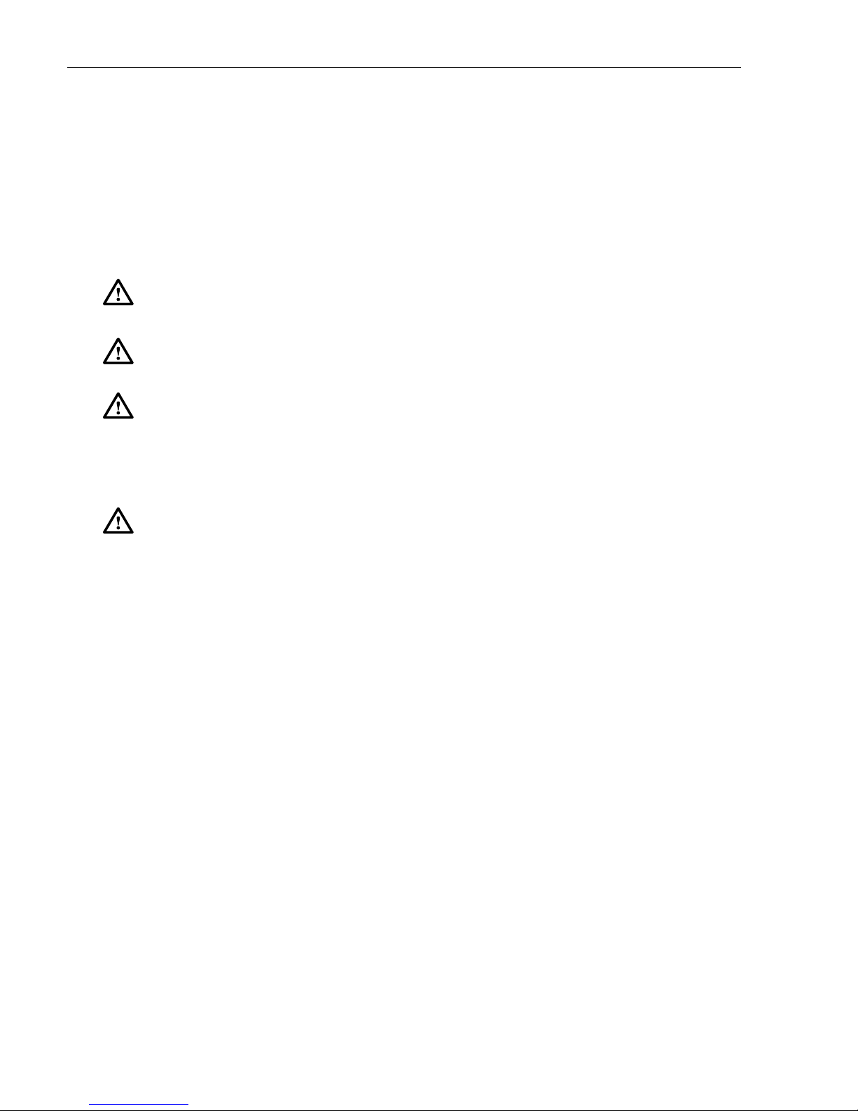
1 TOOLS AND MATERIALS REQUIRED
12494-B
12495-B
12496-B
cm
1
31
12825-a
12497-B
17721-A
18406-A
The tools and materials required for mounting the NG4access frame on a raised floor are
specified in Table 1 and Table 2.
TOOL PICTURE
Adjustable wrenches (2)
0.25 to 1 inch (8 to 25.4 mm)
Crow bar
Drill with metal and concrete drill bits
TECP-90-708 • Issue 5 • April 2017
Table 1. Tools Required
Ruler or tape measure
File
Torque wrench
Note: Capable of 60 ft.-lbs. (81 Nm)
Allen wrench (5/16-inch)
Note: Used for leveling frame
© 2017, CommScope, Inc.
Page 1
Page 8
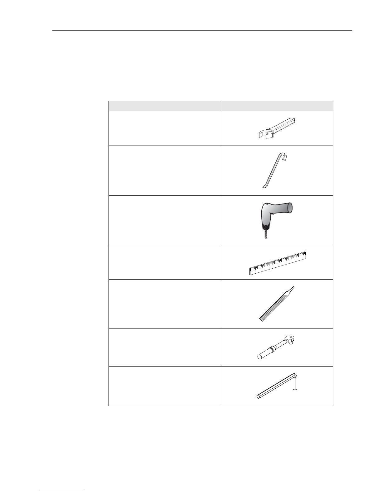
TECP-90-708 • Issue 5 • April 2017
12499-B
12500-B
12501-B
12502-B
12506-B
12504-B
12824-A
TOOL PICTURE
Hacksaw
Hammer
Jigsaw: with blades for cutting floor tile
and metal
Table 1. Tools Required, continued
Level
Set of combination open end/box wrenches
0.25 to 1 inch (8 to 25.4 mm)
Set of sockets
0.25 to 1 inch (8 to 25.4 mm)
Crimping tool
0.25 to 0.3 inches (6.35 to 7.62 mm)
Note: Used for grounding frame
Page 2
© 2017, CommScope, Inc.
Page 9
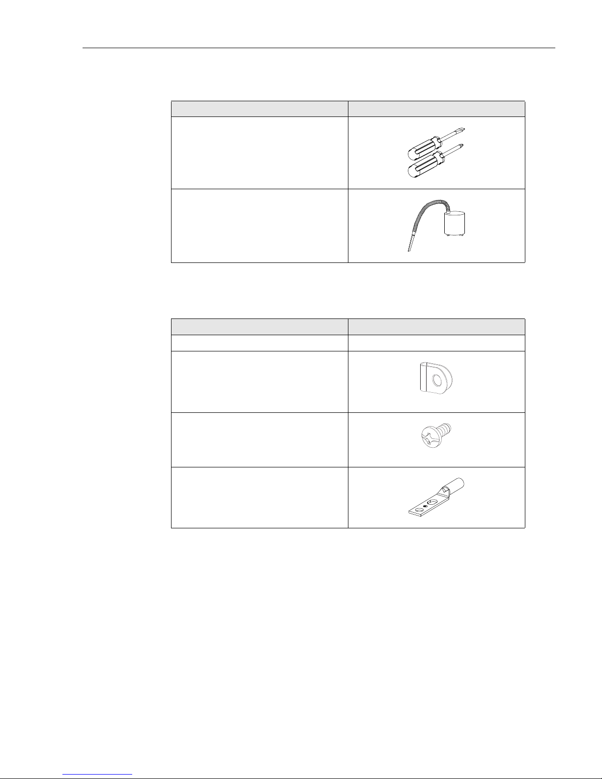
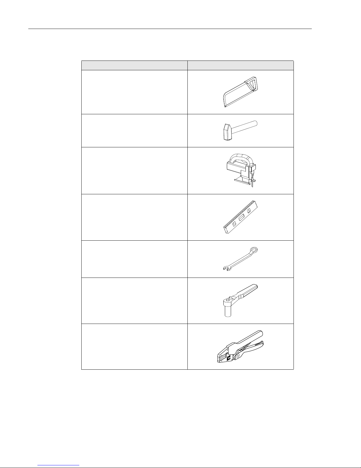
Table 1. Tools Required, continued
12503-B
12505-B
18413-A
18414-A
12498-B
TOOL PICTURE
Flat tip and Phillip screwdrivers
(#1, #2, and #3)
Vacuum
Table 2. Ground Wire Kit Components (Accessory)
TECP-90-708 • Issue 5 • April 2017
ITEM DESCRIPTION/PICTURE
Ground cable (13 ft.) #6 AWG (4.1 mm) solid copper wire
Nylon cable clamps (8)
12-24 x 0.5 inch screws
2-hole copper compression lug (1) with
0.75-inch hole spacing.
Note: Accommodates #6 AWG wire
© 2017, CommScope, Inc.
Page 3
Page 10
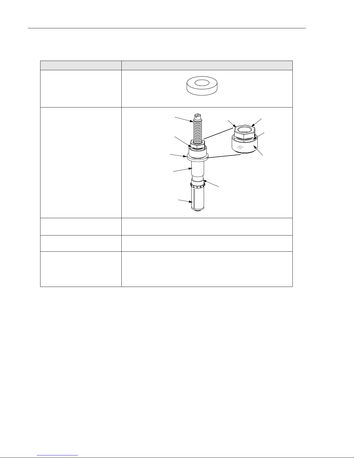
TECP-90-708 • Issue 5 • April 2017
STUD
TORQUE LIMITING HEX NUT
METAL SLEEVE
NYLON SPACER
EXPANDABLE CONE
FLAT W ASHER
TOP FLANGE
(SHEARS OFF)
PLASTIC COVER
NOTE: ONE PIECE
TORQUE NUT
18008-B
ITEM PICTURE
Hold-down washer (4)
(provided with frame)
Concrete floor frame
installation kit
(four anchor bolts)
Table 3. Other Components Used
21899-A
Zone 2/Zone 4 Raised Floor
Mounting Kit
Raised Floor Cable Clamp
Bracket Kit (separately ordered)
Large Cable Clamp Kit
(separately ordered)
Refer to Table 4
This kit is required if cables will be routed into the frame from under the
floor. For more information, refer to Section 5 on Page 35
This kit is required, in addition to the Raised Floor Cable Clamp Bracket
Kit if large cables will be routed into the frame from under the floor.
Large cables are defined as having an Outside Diameter (OD) of 0.8 in.
(2.03 cm) up to 1.03 in. (2.61 cm). For more information, refer to
Section 5 on Page 35
Page 4
© 2017, CommScope, Inc.
Page 11
TECP-90-708 • Issue 5 • April 2017
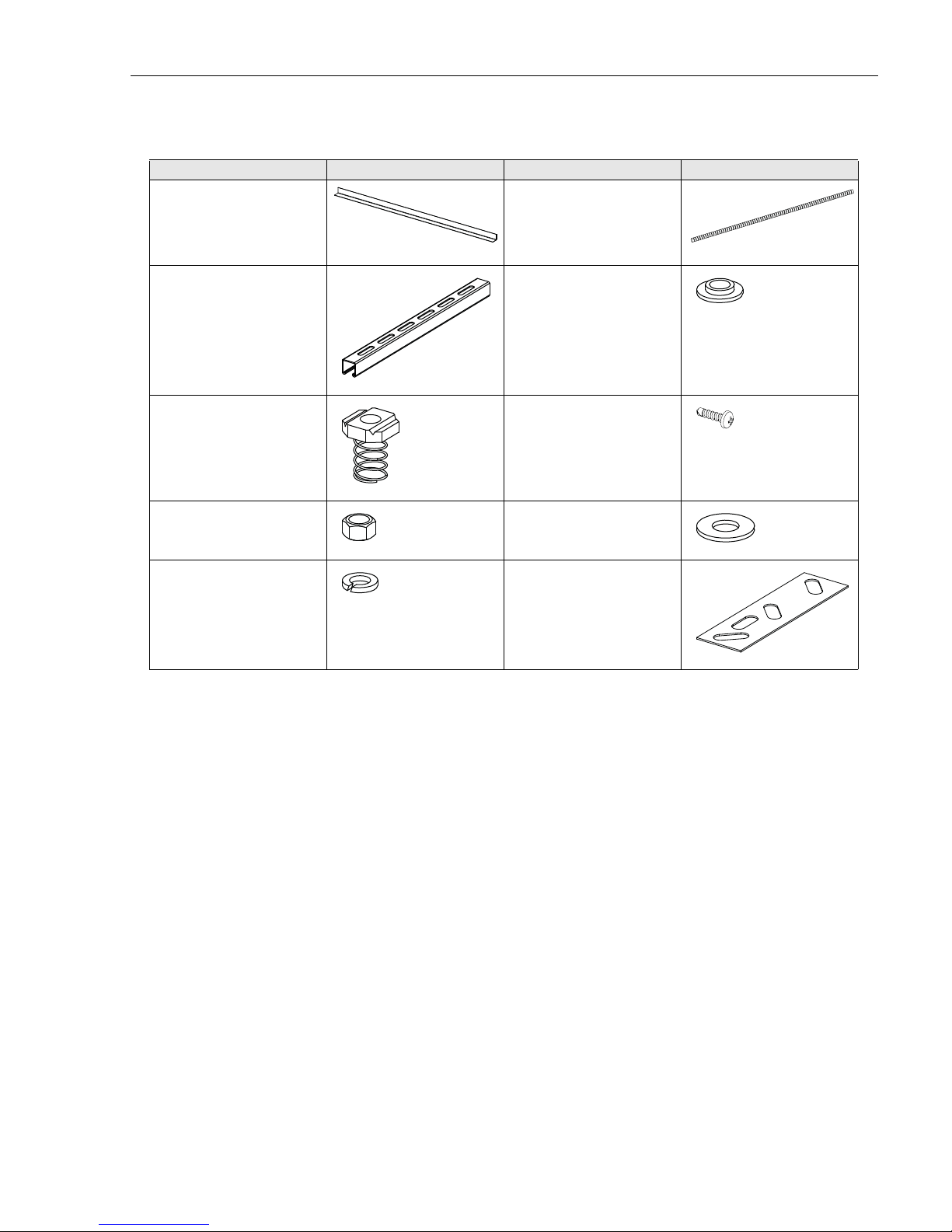
Table 4. Raised Floor Mounting Kit Components
ITEM PICTURE ITEM PICTURE
Edge protector (1) 72 in. Threaded rod (4) 5/8”-11
x 30” long
Unistrut
10 ft. long
Unistrut nut
with spring (4)
Hex nut heavy (12)
5/8” x 11
Split lock washer (12)
5/8”
Plastic shoulder washer
(4)
(Note: Not used)
Wood screw (16)
Flat washer (12) 5/8”
Hold down plate (2)
Note: Not used
© 2017, CommScope, Inc.
Page 5
Page 12
TECP-90-708 • Issue 5 • April 2017
2 FOOTPRINT OF FRAME AND FIBER OPTIC STORAGE PANEL (FOTSP)
Figure 1 shows the frame footprint. Figure 2 shows the FOTSP footprint. The FOTSP is
installed adjacent to the frame on the left side of the frame looking from the front.
29.84 IN. (75.79 CM)
2-7/8 IN.
(7.30 CM)
22-
27/32 IN. (58.02 CM)
23.89 IN.
(60.68 CM)
13 IN.
(33.02 CM)
9-5/8 IN.
(23.45 CM)
13/16 IN.
7-
(19.84 CM)
FRONT
8-5/16 IN.
(21.11 CM)
25-1/2 IN. (64.77 CM)
Figure 1. Frame Footprint (Optional Template Shown)
11.88 IN. (
3.75 IN. (9.52 CM)
10.90 IN.
(27.69 CM)
18.98 IN.
(48.21 CM)
25162-A
1.0 IN. (2.54 CM) DIAMETER
(4) PLACES
30.17 CM)
4.0 IN. (10.16 CM)
23.98 IN.
(60.91 CM)
Page 6
© 2017, CommScope, Inc.
RADIUS 1.0 IN.
2.5 IN.
(6.35 CM)
FRONT
6.88 IN. (17.47 CM)
Figure 2. FOTSP Footprint
(2.54 CM)
SLOT 1.75 X 1.0 IN.
(4.44 X 2.54 CM)
25243-A
Page 13
3 MOUNTING THE FRAME ON A RAISED FLOOR
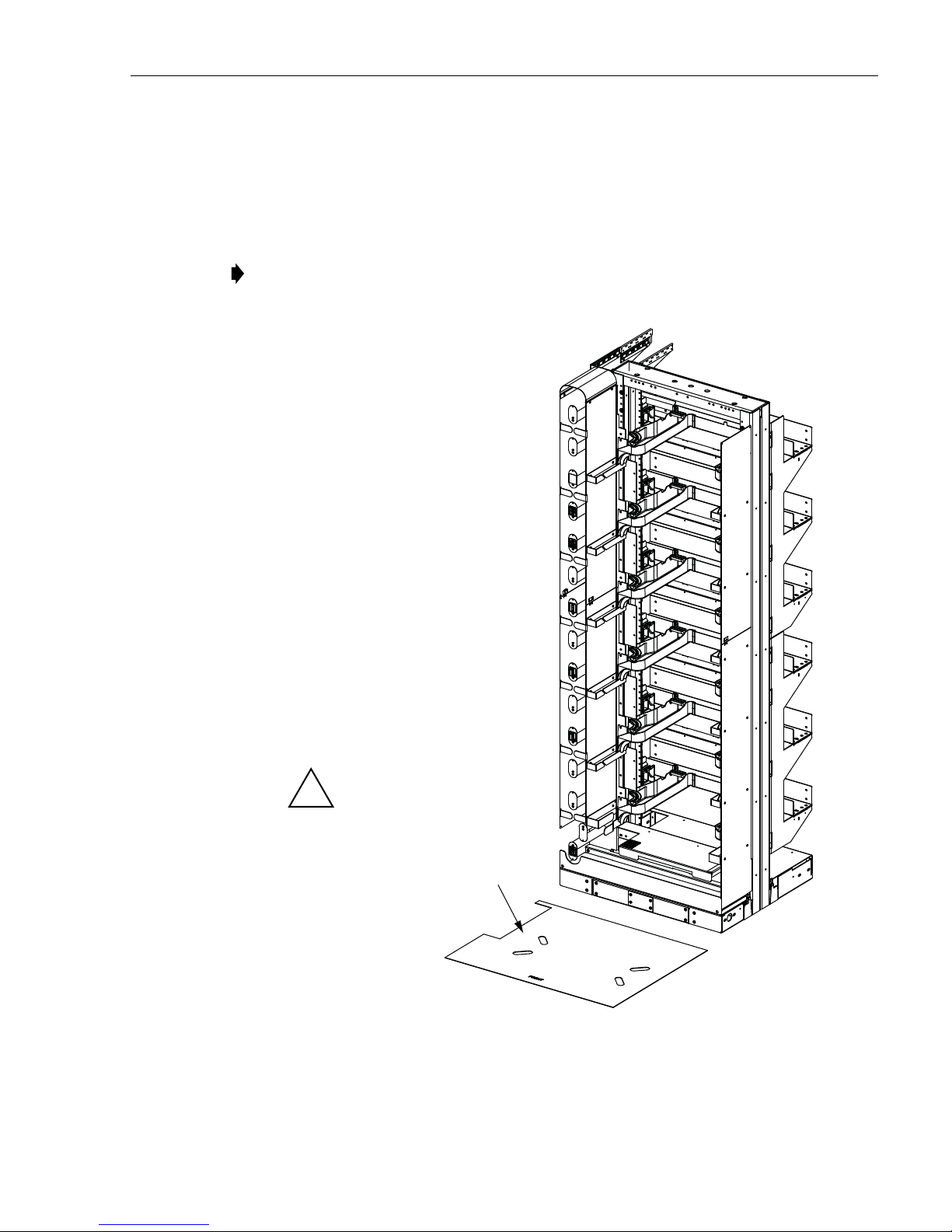
To mount the frame on a raised floor, use the following procedure.
1. Unpack the frame.
2. Set out the frame and optional template/isolation pad as shown in Figure 3.
Note: Storage spools may loosen during shipment. Check storage spools for looseness.
Tighten spool cover screws if spools are loose.
TECP-90-708 • Issue 5 • April 2017
NOTE: TEMPLA TE/ISOLATION PAD
NOT REQUIRED FOR INSTALLATION
CAUTION: USE APPROPRIATE
EQUIPMENT TO LIFT RACK
!
OPTIONAL
TEMPLATE/ISOLATION PAD
(ORDERED SEPARATELY)
Figure 3. Setting Out Frame and Optional Template/Isolation Pad
25045-A
Page 7
© 2017, CommScope, Inc.
Page 14
TECP-90-708 • Issue 5 • April 2017
FRONT AISLE
(4-FEET
RECOMMENDED
MINIMUM)
REAR AISLE
(3-FEET
RECOMMENDED
MINIMUM)
25046-B
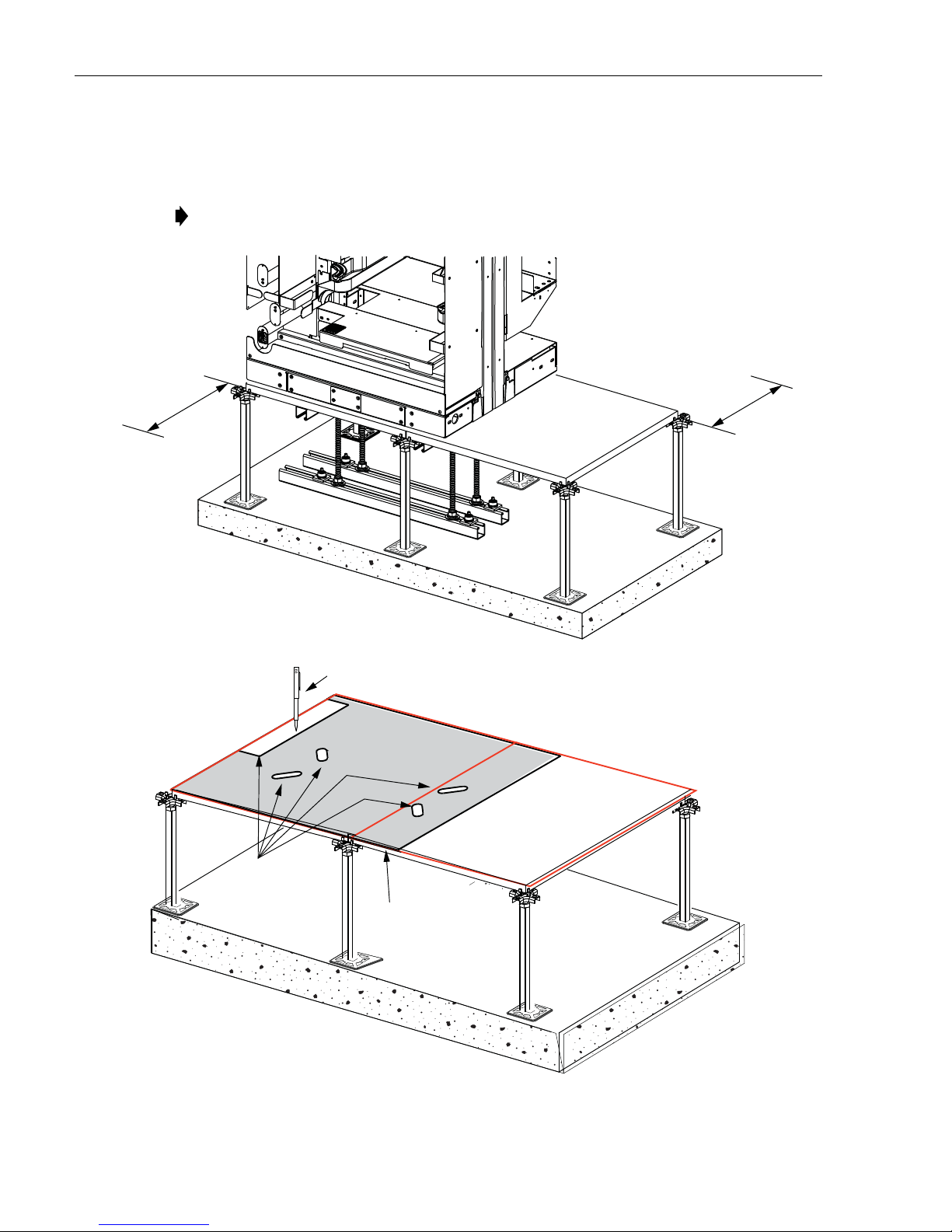
3. Determine the frame location taking note of the clearance requirements shown in Figure 4.
Place the optional template/isolation pad on the floor tiles and mark the tile as shown. If
installing without a template, refer to Section 2 on Page 6 for installation dimensions.
Note: If optional FOTSP is present, see Figure 5.
MARK THESE
LOCATIONS
PENCIL
ALIGN FRONT OF
TEMPLATE/ISOLATION PAD
WITH EDGE OF TILE
25271-A
Figure 4. Determining Frame Location
Page 8
© 2017, CommScope, Inc.
Page 15
TECP-90-708 • Issue 5 • April 2017
25270-A
MARK HOLES
AND CUTOUT
ON TEMPLATE
ALIGN FRONT OF
TEMPLATE/ISOLATION PAD
WITH EDGE OF TILE
PENCIL
FOTSP
LOCATION
FRONT
25268-A
EXAMPLE ONLY (OTHER ARRANGEMENTS ARE POSSIBLE)
FOTSP FOOTPRINT FRAME FOOTPRINT
MARK CUTOUT
FOR FOTSP
IF FLOOR ENTRY
WILL BE USED
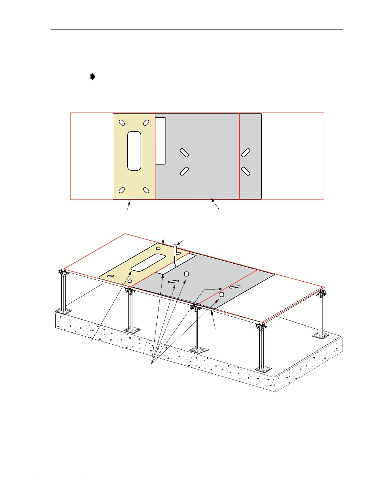
4. If FOTSP will be installed, also mark out and cut out a hole for the FOTSP to the left of
the frame template. Figure 5 shows an example.
Note: The optional FOTSP is only shown in this illustration in the frame installation
procedure. For the separate FOTSP installation procedure, refer to Section 4 on Page 30.
Figure 5. FOTSP and Frame Footprints on Floor Tiles
Page 9
© 2017, CommScope, Inc.
Page 16
TECP-90-708 • Issue 5 • April 2017
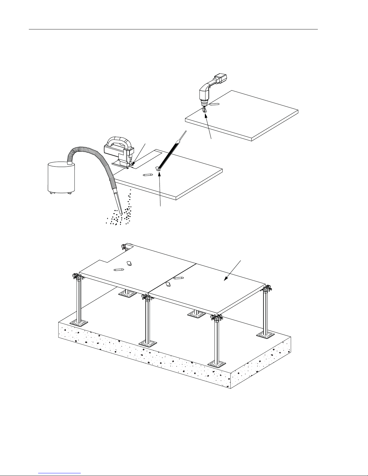
DRILL
PILOT HOLES
VACUUM
AS REQUIRED
SET FLOOR TILES
ON PEDESTALS
25048-A
FILE
ALL EDGES
CUT
TILES
5. Remove and cut the tiles, file all edges, and set the floor tiles on the pedestals, as shown in
Figure 6.
Figure 6. Setting Floor Tiles on Pedestal
Page 10
© 2017, CommScope, Inc.
Page 17
FILE
ENDS
PAINT ENDS
(OPTIONAL)
NOTE: MEASURE FROM CONCRETE
TO 1-5/8 IN. (+/- 3/8 IN.) ABOVE FLOOR TILE
1-5/8 IN.
(+/- 3/8 IN.)
THREADED
ROD
25049-A
TECP-90-708 • Issue 5 • April 2017
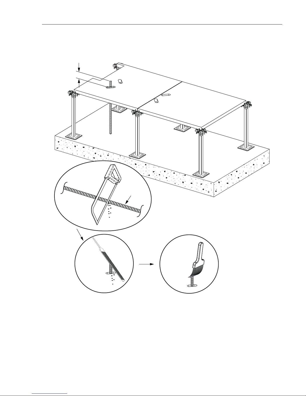
6. Cut threaded rod to floor height +1-5/8in. (+/- 3/8 in.) (four places). Refer to Figure 7.
Figure 7. Cutting Threaded Rod
Page 11
© 2017, CommScope, Inc.
Page 18
TECP-90-708 • Issue 5 • April 2017
7. Cut the unistrut to the required length, as shown in Figure 8.
TOP VIEW
CUT TO REQUIRED LENGTH
29.8 IN.
(75.8 CM)
22.1 IN.
(38.4 CM)
21.4 IN.
(36.6 CM)
TOP-RIGHT UNISTRUT SHORTENED
TO ALLOW FOR TOP OF PEDESTAL
CUT TO REQUIRED
LENGTH
(SEE TOP VIEW)
CUT
NOTE: LOWER UNISTRUT CUT LENGTH
IS SHOWN FOR ONE FRAME INSTALLATON.
Page 12
© 2017, CommScope, Inc.
25050-A
Figure 8. Cutting Unistrut
FILE EDGES
PAINT FILED EDGES
(OPTIONAL)
E
N
V
O
I
N
S
-
C
O
R
O
R
P
A
T
I
N
Page 19

TECP-90-708 • Issue 5 • April 2017
8. Assemble the washer and hex nut onto the threaded rod and insert the threaded rod in the
floor tile. Plumb the threaded rods from front to back and mark concrete. Repeat these
steps using the same threaded rod for the three remaining slots. Refer to Figure 9.
PLUMB THREADED
ROD FROM FRONT
TO BACK
HEX NUT
WASHER
CENTER
THREADED
ROD IN SLOT
MAKE SURE THREADED R OD
DOES NOT TOUCH CONCRETE
SIDE VIEW
MARK CENTER
REPEAT STEPS USING SAME THREADED ROD
FOR REMAINING THREE SLOTS
25051 -A
Figure 9. Marking Concrete With Threaded Rod
Page 13
© 2017, CommScope, Inc.
Page 20

TECP-90-708 • Issue 5 • April 2017
9. Remove the threaded rod assembly and set the floor tiles aside. Use a ruler or straight edge
to draw lines on the concrete. Refer to Figure 10.
THREADED ROD
ASSEMBLY
SET FLOOR
TILES ASIDE
DRAW LINES
ON CONCRETE
Page 14
© 2017, CommScope, Inc.
25052-A
RULER OR
STRAIGHT EDGE
Figure 10. Marking Concrete
Page 21

10. Center unistruts over lines on concrete. Refer to Figure 11.
TOP VIEW
25053-A
CENTER UNISTRUT
ON LINE
TECP-90-708 • Issue 5 • April 2017
Figure 11. Centering Unistruts on Lines
© 2017, CommScope, Inc.
Page 15
Page 22

TECP-90-708 • Issue 5 • April 2017
11. Set the floor tiles on the pedestals. Install a spring nut in each unistrut. Assemble the 5/8inch hex nut, 5/8-inch lock washer, and 5/8-inch washer onto the threaded rod (12A).
Install the threaded rod assembly (12B) into the spring nut. Refer to Figure 12.
SPRING NUT INSTALLED,
SIDE VIEW
SLIDE SPRING NUT
INTO END OF UNISTRUT
THREADED ROD
5/8-INCH HEX NUT
5/8-INCH WASHER
SPRING NUT
INSTALLED
12A: ASSEMBLE 5/8-INCH HEX NUT, 5/8-INCH LOCK WASHER,
AND 5/8-INCH WASHER ONTO THREADED ROD
5/8-INCH LOCK WASHER
SPRING NUT
THREADED
ROD ASSEMBLY
UNISTRUT
LEAVE SPACE BETWEEN BOTTOM
OF THREADED ROD AND TOP, INSIDE
SURFACE OF UNISTRUT
Figure 12. Setting Floor Tiles on Pedestals
Page 16
© 2017, CommScope, Inc.
12B: INSTALL THREADED ROD ASSEMBLY
INTO SPRING NUT
25054-A
Page 23

TECP-90-708 • Issue 5 • April 2017
PLUMB THREADED R OD
FROM SIDE TO SIDE
25055-A
ANCHOR PLATE
X
X
X
X
UNISTRUT
THREADED ROD ASSEMBLY
AND SPRING NUT
MARK CONCRETE
(FOUR PLACES)
TOP VIEW
INSTALL REMAINING
THREADED ROD
ASSEMBLIES
12. Plumb the threaded rod assembly and mark anchor plate location on concrete. Install three
remaining threaded rod assemblies in the same manner. See Figure 13.
Figure 13. Installing Threaded Rod Assemblies
© 2017, CommScope, Inc.
Page 17
Page 24

TECP-90-708 • Issue 5 • April 2017
13. Set the floor tiles and unistrut assemblies aside and drill holes at the anchor bolt locations.
Refer to Figure 14.
VACUUM AS
REQUIRED
HOLE DIMENSIONS:
DIAMETER: 0.71-IN. (18MM)
DEPTH: 3-15/16-IN. (100MM)
DRILL HOLES (4)
Page 18
© 2017, CommScope, Inc.
25056-A
Figure 14. Drilling Holes
Page 25

TECP-90-708 • Issue 5 • April 2017
INSERT ANCHOR BOLT
ASSEMBLY INTO HOLE
ANCHOR BOLT ASSEMBLY
WASHER
TORQUE NUT
ANCHOR SLEEVE
THREADED ROD
25057-A
14. Thread the washer and torque nut onto the threaded rod of the an chor bolt. The washer
should touch the top of the anchor sleeve. Insert the anchor bolt assembly into the hole just
drilled. Using a hammer, tap the anchor bolt assembly into the hole until the washer
touches the concrete. Refer to Figure 15.
Figure 15. Setting Anchor Bolts
Page 19
Page 26

TECP-90-708 • Issue 5 • April 2017
15. Pre-torque the anchor bolts approximately 30 ft-lbs (41 Newton meters) (16A). Loosen the
torque nut several turns (16B). Then remove the torque nut and washer (16C). Refer to
Figure 16.
TORQUE WRENCH
16A: PRE-TORQUE ANCHOR BOLT
TO APPROXIMATELY 30 FT-LBS
(41N-m)
LOOSEN
TORQUE NUT
16-B: LOOSEN TORQUE NUT
Figure 16. Pre-torquing Anchor Bolts
25058-A-A
TORQUE NUT
WASHER
THREADED ROD
16-C: REMOVE TORQUE NUT
AND WASHER
Page 20
© 2017, CommScope, Inc.
Page 27

TECP-90-708 • Issue 5 • April 2017
25059-A
UNISTRUT ASSEMBLY CONSISTS OF A
UNISTRUT AND THREADED ROD ASSEMBLY (2)
ANCHOR BOLT THREADED ROD (4)
TORQUE NUT
FLAT W ASHER
ANCHOR PLATE
THREADED
ROD
17A: ASSEMBLE ANCHOR PLATE,
FLAT W ASHER, AND TORQUE NUT
ONTO THREADED ROD
TOP FLANGE
TORQUE NUT
TORQUE WRENCH
17B: TIGHTEN TORQUE NUT
UNTIL TOP FLANGE SHEARS OFF
66
70
68
60
62
64
0
FT-LB
17C: THE TORQUE NUT WILL BE
CORRECTLY SET AT 60 FT-LBS (81N-m)
16. Position the unistrut assemblies over the anchor bolt threaded rods. Assemble the anchor
plate, flat washer, and torque nut onto the threaded rod (17A). Tighten torque nut until top
flange shears off (four places) (17B). The torque nut will be correctly set at 60 ft-lbs (81
Newton meters) (17C). Refer to Figure 17.
Figure 17. Positioning Unistrut Assemblies
© 2017, CommScope, Inc.
Page 21
Page 28

TECP-90-708 • Issue 5 • April 2017
UNISTRUT
FLAT W ASHER 5/8-11-INCH
SPLIT LOCK
WASHER 5/8-INCH
HEX NUT 5/8-INCH
NOTE: ALLOW SPACE BETWEEN
UNISRUT AND FLOOR TILE TO MAKE SURE
FLOOR TILE IS NOT RAISED OFF PEDESTALS.
25060-A
FLOOR TILE
UNISTRUT
SPACE
SIDE VIEW
17. Assemble hex nuts, split lock washers, flat washers, unistruts, and floor tiles onto threaded
rods. Refer to Figure 18.
Figure 18. Placing Floor Tiles on Threaded Rods
Page 22
© 2017, CommScope, Inc.
Page 29

TECP-90-708 • Issue 5 • April 2017
18. Cut out edge protectors to the required length for the slots in the floor tile. Secure the edge
protectors to the floor tiles using self-drilling screws (provided). Refer to Figure 19.
SELF-DRILLING
SCREWS (PROVIDED)
CUT TO REQUIRED
LENGTH
DRILL PILOT HOLES
NOTE: EDGE PROTECTOR MAY
BE CUT TO FIT AROUND PEDESTAL
NOTE: INSTALL EDGE PROTECTOR ON ALL SIDES
OF CABLE ENTRANCES (RECOMMENDED)
25061-A
Figure 19. Installing Edge Protectors
Page 23
© 2017, CommScope, Inc.
Page 30

TECP-90-708 • Issue 5 • April 2017
19. Plumb threaded rod assemblies (4) and tighten hex nuts (4). Refer to Figure 20.
PLUMB THREADED
ROD ASSEMBLIES
FROM SIDE TO SIDE
TIGHTEN
HEX NUTS (4)
25062-A
Figure 20. Plumbing Threaded Rods
Page 24
© 2017, CommScope, Inc.
Page 31

TECP-90-708 • Issue 5 • April 2017
20. Hand tighten the hex nuts to raise unistruts to floor tile. Refer to Figure 21.
MAKE SURE FLOOR TILES ARE
!
NOT RAISED OFF PEDESTALS
25063-A
FLOOR TILE
UNISTRUT
(SHADED FOR CLARITY)
HAND TIGHTEN
HEX NUTS TO
RAISE UNISTRUTS
TO FLOOR TILE
Figure 21. Raising Unistruts to Floor Tile
Page 25
© 2017, CommScope, Inc.
Page 32

TECP-90-708 • Issue 5 • April 2017
FRONT
VIEW
MOUNTING SLOTS
(PARTIALLY SHOWN)
LOWER
TROUGH
BACK
LOWER
TROUGH
BASE
GUARD BOX
COVER
24995-A
REAR VIEW
MOUNTING SLOTS
(PARTIALLY SHOWN)
REAR COVER
25065-A
21. Remove the frame front and rear troughs to access mounting slots. Refer to Figure 22.
(Caution: Do not attempt to lift or move the frame without appropriate equipment.)
Page 26
© 2017, CommScope, Inc.
Figure 22. Removing Troughs
Page 33

22. Position the frame on the optional template/isolation pad and floor tile. Install hardware
SET SCREW
(FOUR PLACES)
SEE 23B, BELOW
TECP-90-708 • Issue 5 • April 2017
(four places). Do not fully tighten (23A). Use 5/16-inch allen wrench and adjust set screws
(4) to level rack. Refer to Figure 23.
ALIGN SLOTS IN RACK AND
TEMPLATE/ISOLATION PAD
WITH THREADED R ODS
OPTIONAL
TEMPLATE/ISOLATION PAD
(SHADED FOR CLARITY)
HEX NUT
5/8-11-INCH
SPLIT LOCK
WASHER 5/8-INCH
HOLDDOWN W ASHER
(PROVIDED WITH RACK)
THREADED ROD
23A: INSTALL HOLDDOWN WASHER,
SPLIT WASHER 5/8-INCH AND HEX NUT 5/8-11 INCH
Figure 23. Positioning Frame on Optional Template/Isolation Pad and Floor Tile
(DO NOT FULLY TIGHTEN)
25066-A
23B: USE 5/16-INCH ALLEN WRENCH
AND ADJUST SET SCREW TO
LEVEL RACK
Page 27
© 2017, CommScope, Inc.
Page 34

TECP-90-708 • Issue 5 • April 2017
TIGHTEN HEX NUTS UNTIL
SPLIT LOCK WASHER IS FLATTENED
DO NOT FULLY TIGHTEN
OR RAISE FLOOR TILES
SIDE VIEW
25067-A
NOTE: MAKE SURE RACK REMAINS LEVEL
!
23. Use wrench to tighten hex nuts under floor tile. Do not fully tighten. Refer to Figure 24.
Page 28
© 2017, CommScope, Inc.
Figure 24. Tightening Hex Nuts 1
Page 35

25068-A
TIGHTEN HEX NUTS (4)
UNDER FLOOR TILE
TIGHTEN HEX NUTS (4)
ABOVE FLOOR TILE
NOTE: MAKE SURE RACK REMAINS LEVEL
!
TECP-90-708 • Issue 5 • April 2017
24. Use wrench (5/8-inch) to tighten hex nuts above floor tile (four places). Then fully tighten
hex nuts under floor tile. Refer to Figure 25.
25. If cables will be routed into the frame from under the floor:
Figure 25. Tightening Hex Nuts 2
© 2017, CommScope, Inc.
Page 29
Page 36

TECP-90-708 • Issue 5 • April 2017
a. Install the Raised Floor Cable Clamp Bracket Kit (separately ordered). For
instructions on how to install the kit, refer to Section 5 on Page 35 .
b. If the cables from under the floor will be routed into a splice chassis, install a spool
bracket assembly. For instructions, refer to Section on Page 46.
26. Re-install front and rear trough as shown in Figure 26.
27. Ground the frame. Refer to Section 9 on Page 49.
FRONT
VIEW
LOWER
TROUGH
BACK
REAR
GUARD BOX
LOWER
TROUGH
GUARD BOX
COVER
BASE
25069-A
Figure 26. Re-installing Troughs
4 INSTALLING A FIBER OPTIC STORAGE PANEL (FOTSP)
A Fiber Optic Storage Panel (FOTSP), installed onto the left side of the NG4access frame as
looking from the front, provides storage space on the rear for Fiber Optic Terminal Equipment
patch cords. The FOTSP is 12 inches wide. For a view of the frame and FOTSP footprints, refer
to Section 2 on Page 6. Use the following procedure to install a FOTSP.
1. If the front trough covers, front guard box, and the rear guard box, are present on the
frame, remove them. Figure 26 above shows the same components, but being installed.
2. If cables will enter the FOTSP from under the floor, saw out a cable entry hole, referring to
Figure 2 on Page 6 for hole location and dimensions.
3. Unpack the FOTSP and set it up next to the frame, with the cross-frame troughs on the rear
side corresponding to the location of the cross-frame troughs on the frame.
Page 30
© 2017, CommScope, Inc.
Page 37

4. Remove the FOTSP front cover, referring to Figure 27.
25258-A
FOTSP
FRONT
COVER
25260-A
FOTSP
BACK
COVER
FOTSP
COVER
PLATE
TECP-90-708 • Issue 5 • April 2017
Figure 27. Removing FOTSP Front Cover
5. Remove the FOTSP back cover and cover plate (Figure 28).
Figure 28. Removing FOTSP Back Cover and Cover Plate
Page 31
© 2017, CommScope, Inc.
Page 38

TECP-90-708 • Issue 5 • April 2017
25257-A
TIE BRACKET
(2 PLACES)
TROUGH
TIE
(6 PLACES)
HOLE
COVER
EDGE
PROTECTOR
6. Secure the FOTSP to the NG4access frame by installing tie brackets in two places and
trough ties in six places as shown in Figure 29.
Note: Refer also to the detailed views in Figure 30 and Figure 31.
Figure 29. Installing Brackets
Page 32
© 2017, CommScope, Inc.
Page 39

TECP-90-708 • Issue 5 • April 2017
TOP CROSS-FRAME TROUGH
REAR VIEW
3RD-DOWN CROSS-FRAME TROUGH
TOP TIE
BRACKET
MID-FRAME
TIE BRACKET
25262-A
PLACE ONE
TROUGH TIE
ON BOTTOM
SIDE OF
EACH
JUNCTION
OF TROUGHS
3RD DOWN CROSS-FRAME TROUGH
REAR VIEW
Figure 31. Rear View With Frame Tilted to Show Bracke ts Under Trough
Figure 30. Rear View of Bracket Locations
25263-A
MID-FRAME TIE BRA CKET
© 2017, CommScope, Inc.
Page 33
Page 40

TECP-90-708 • Issue 5 • April 2017
25261-A
1/4-20 HEX BOLTS (2)
1/4 FLAT WASHER (2)
1/4 LOCK WASHER (2)
1/4-20 HEX NUT (2)
EDGE
PROTECTOR
REAR VIEW
(REAR TROUGH NO T
SHOWN FOR CLARITY)
NOTE: INSTALL SAME HARDWARE
IN ANALOGOUS LOCATION
ON FRONT OF FRAME AND FOTSP
7. To secure the bases of the frame and FOTSP together, install two hex bolts on the rear of
the frame as shown in Figure 32, then, as noted, install two hex bolts in the analogous
location on the front of the frame.
Page 34
© 2017, CommScope, Inc.
Figure 32. Bolting Together Frame and FOTSP Bases
Page 41

8. Install the edge protector on the FOTSP in the location shown in Figure 32.
9. Install the hole cover in the location shown in Figure 29 on Page 32.
10. Re-install the front and rear troughs, as shown in Figure 26 on Page 30.
11. Re-install FOTSP front and rear guard boxes (reverse of steps 3 and 4, and reverse of what
is shown in Figure 27 on Page 31 and Figure 28 on Page 31).
5 INSTALLING A RAISED FLOOR CABLE BRACKET
If cables will be brought into the frame from under the raised floor, a Raised Floor Standard
Cable Clamp Bracket (available from CommScope) must be installed on the rear side of the
frame in the bottom right corner.
The kit is designed for standard size cables, with an Outside Dia meter (OD) of up to 0.8 in.
(2.03 mm). If large cables are to be installed, with an OD in the range from 0.8 to 1.03 in. (2.03
to 26.16 mm), a large cable kit (NG4-ACCRFCLMP3) is also required.
This procedure covers both standard and large cables, and assumes that the installer has the kit
or kits required.
TECP-90-708 • Issue 5 • April 2017
Use the following procedure to install a raised floor cable clamp bracket.
1. Determine whether the cables to be installed are standard or large as defined above. Set
out the bracket plate (largest piece in the kit) and identify the hole pattern to be used for
mounting cables, referring to Figure 33 on Page 36. There are separate hole patterns for
large and standard cables.
© 2017, CommScope, Inc.
Page 35
Page 42

TECP-90-708 • Issue 5 • April 2017
25125-A
LARGE CABLE GROMMET PLACEMENT
STANDARD CABLE GROMMET PLACEMENT
ROW A
ROW B
ROW E
18-32 x 5/16 IN.
SCREWS
18-32 x 5/16 IN.
SCREWS
18-32 x 5/16 IN.
SCREW
18-32 x 5/16 IN.
SCREW
NOTE: DO NOT DRIVE THE SCREW HEADS TIGHT AGAINST THE BRACKET. ALLOW SUFFICIENT SPACE
BETWEEN THE SCREW HEADS AND BRACKET FOR THE CABLE CLAMPS TO BE HUNG ON THE SCREWS.
ROW F
Figure 33. Grommet Placement on Bracket
Page 36
© 2017, CommScope, Inc.
Page 43

TECP-90-708 • Issue 5 • April 2017
18-32 x 5/16 IN.
PANHEAD SCREW
(24 PLACES,
EACH SIDE; 48 TOTAL)
25127-A
NOTE: DO NOT DRIVE THE SCREW
HEADS TIGHT A GAINST THE
BRACKET. ALLOW SUFFICIENT SPACE
BETWEEN THE SCREW HEADS AND
BRACKET FOR THE CABLE CLAMPS
TO BE HUNG ON THE SCREWS.
18-32 x 5/16 IN.
PANHEAD SCREW
(12 PLACES, EACH SIDE;
24 TOT AL)
25128-A
NOTE: DO NOT DRIVE THE SCREW
HEADS TIGHT A GAINST THE
BRACKET. ALLOW SUFFICIENT SPACE
BETWEEN THE SCREW HEADS AND
BRACKET FOR THE CABLE CLAMPS
TO BE HUNG ON THE SCREWS.
2. Install 8-32 x 5/16 inch pan head screws as shown in Figure 33, Figure 34, and Figure 35.
Leave enough space between the screw heads and bracket for the cable clamps to be hung
on the screws in a later step.
Figure 34. Standard Cable Screw Placement
Figure 35. Large Cable Screw Placement
© 2017, CommScope, Inc.
Page 37
Page 44

TECP-90-708 • Issue 5 • April 2017
25168-A
REAR VIEW
OF FRAME
3. If the frame has a splice chassis:
a. Remove the splice chassis cover (if present) from the bottom rear of the NG4access
frame, as shown in Figure 36. To do this, remove the two #8 pan head screws and two
star washers securing the cover to the frame. Set aside these items for re-installing the
cover later.
REAR VIEW
OF FRAME
25137-A
Figure 36. Removing Front Plate from Frame
b. Fully slide out the splice chassis (if present), as shown in Figure 37.
Page 38
© 2017, CommScope, Inc.
Figure 37. Sliding Out the Splice Chassis
Page 45

TECP-90-708 • Issue 5 • April 2017
4. If the frame does not have a splice chassis, remove the cover shown in Figure 38.
REAR VIEW
OF FRAME
25161-A
Figure 38. Removing Rear Cover on a Non-Splice Frame
5. Place the cable bracket into the cable entry hole, and position the holes in the bracket on
the threaded studs, as shown in Figure 39. Install a #10 washer and #10 nut on each
threaded stud. Tighten to 16 inch lbs. (1.8 Newton meters).
Note: This illustration shows a frame without a splice chassis.
© 2017, CommScope, Inc.
Page 39
Page 46

TECP-90-708 • Issue 5 • April 2017
POSITION BRACKET ON
THREADED STUD.
INSTALL #10 WASHER
AND #10 NUT
(TWO PLACES).
TIGHTEN TO 16 INCH-LBS.
(1.8 NEWTON METERS)
25171-A
6. Route the cables to be installed through the entry hole, taking care to position each cable
on the correct side of the raised floor cable breakout per the cable clamp locations shown
in Figure 33 on Page 36.
Note: The Row locations shown in this same figure (Figure 33 on Page 36) will also be
used to figure out the DIM ‘A” values when breaking out the cables in the next step.
7. Prepare each cable as follows, referring to Figure 40:
a. Pull the cable up through the hole.
b. If the cable being installed is an NG4access cable terminated with one or more cabled
module(s), obtain the appropriate DIM ‘A’ length from Table 5 based on where the
cable clamp will be installed on the bracket, measure out this length from the factory
breakout on the cable, and mark the cable at this location as shown in Figure 40. This
is where the cable clamp should be placed on the cable.
Page 40
© 2017, CommScope, Inc.
Figure 39. Installing Bracket in Frame
Page 47

TECP-90-708 • Issue 5 • April 2017
25140-A
OUTER CABLE JACKET
BREAKOUT
DIM ‘A’
CABLE
CLAMP
STANDARD LENGTH
25163-A
OUTER CABLE JACKET
BREAKOUT
DIM ‘A’
CABLE
CLAMP
210 IN. (533.4 CM)
Note: There is no need for further breakout as all NG4acces s cables with cabled modules
are of one standard length.
Table 5. Row Position vs. DIM ‘A’
CABLE SIZE
ROW
POSITION* DI M ‘A’
Standard A 3-1/16 in. (80.96 mm)
Standard B 4-11/16 in. (119.06 mm)
Standard C 5-7/16 in (138.11 mm)
Standard D 7-3/32 in. (180.18 mm)
Large E 3-7/8 in. (98.42 mm)
Large F 6-5/16 (160.34 mm)
* per Figure 33 on Page 36
Figure 40. Cabled Module Assembly Cable Clamp Position and Breakout
c. If the cable being installed is designated for the splice chassis, obtain the appropriate
DIM ‘A’ length from Table 5 based on where the cable clamp will be installed on the
bracket, and measure an additional length of 210 in. (533.4 cm), as shown in
Figure 41. This is where the cable clamp should be placed on the cable. For cable
routing instructions, refer to NG4access ODF Platform Splice Chassis and Splice Tray
User Manual (TECP-90-704).
8. If the cable diameter is 0.8 in (2.0 cm) or less, assemble the “standard” cable clamp at the
cable clamp position (see Figure 42). There are different sizes of grommets, measured by
their inside diameters of 0.4, 0.5, 0.6, and 0.7 in. (1.0, 1.27, 1.52, and 1.78 cm). Select the
grommet with an inside diameter that is one size smaller than the outside diameter of the
cable. After assembling the components on the mounting screws, tighten the screws until
the yokes make contact, then tighten the screws four additional revolutions.
Figure 41. Splice Cable Clamp Position and Breakout
© 2017, CommScope, Inc.
Page 41
Page 48

TECP-90-708 • Issue 5 • April 2017
MOUNTING
SCREWS
(6-32 x 1.75 IN.)
BACK
PLATE
RUBBER
YOKE
25136-A
GROMMET
COVER
Figure 42. Standard Cable Clamp Exploded View
9. If the cable diameter is greater than 0.8 in (2.03 cm) and less than 1-1/32 inch (2.62 cm),
assemble the “large” cable clamp at the cable clamp position (see Figure 43). There are
different sizes of grommets, measured by their inside diameters of 0.8, 0.9, and 1.0 in.
(2.03, 2.29, and 2.54 cm). Select the grommet with an inside diameter that is one size
smaller than the outside diameter of the cable. After assembling the components on the
mounting screws, tighten the screws until the yokes make contact.
Page 42
© 2017, CommScope, Inc.
MOUNTING
SCREWS
(10-32 x 2.00 IN.)
BACK
PLATE
RUBBER
YOKE
25135-A
GROMMET
COVER
LARGE
Figure 43. Large Cable Clamp Exploded View
Page 49

TECP-90-708 • Issue 5 • April 2017
25139-A
CABLE BRACKET
MOUNTING
SCREWS
HANGING
SLOT
CABLE
CLAMP
NOTE: START HANGING CABLE CLAMPS AT
THE BACK OF THE BRACKET, WORK TO THE
REAR OF THE FRAME. LAST FOUR CLAMPS
MAY NEED TO BE INSTALLED BELOW THE
RAISED FLOOR.
REAR OF
FRAME
25141-A
ROW C
ROW D
ROW F
EXAMPLES OF STANDARD
CLAMP POSITIONS
EXAMPLES OF LARGE
CLAMP POSITIONS
Note: Do not continue to tighten as instructed for the standard cable clamp in Step 8.
Note: If large cables are being installed, the last four cable clamps may need to be
assembled on the cable below the raised floor.
10. Beginning at the back of the cable clamp bracket (in the middle of the frame), hang the
cable clamps by positioning the hanging slots on the mounting screws, as shown in
Figure 44. Be sure to position the clamps on th e correct mounting screws as indicated in
Figure 45. Work from the back of the bracket towards the rear of the frame. After hanging
a cable clamp on the mounting screws, tighten the mounting screws until secure.
Figure 44. Hanging Cable Clamps on Bracket
Figure 45. Correct Placement of Cable Clamps
© 2017, CommScope, Inc.
Page 43
Page 50

TECP-90-708 • Issue 5 • April 2017
25134-A
INSTALLED
CABLES
AND CLAMPS
PROTECTION
PLATE
11. If the frame does not have a splice chassis, re-install the cover for non-splice applications
(removed in Step 4 on Page 39).
Note: See TECP-90-713 for instructions on installing auxiliary cable spools for use with
NG4access cabled module assemblies routed into the frame from the raised floor bracket.
6 INSTALLING A SPOOL BRACKET ASSEMBLY (FOR FRAME WITH SPLICE CHASSIS)
If the frame on which the bracket was just installed has a splice chassis, the Spool Bracket
Assembly (provided with the Raised Floor Standard Cable Clamp Bracket Kit) must also be
installed.
Use the following procedure.
1. Install the protection plate (second largest piece in the Raised Floor Standard Cable Clamp
Bracket Kit) in the location shown in Figure 46. Secure the plate using the mounting
screws provided. Torque to 16 in.-lbs. (1.8 Newton meters).
Page 44
© 2017, CommScope, Inc.
Figure 46. Installing Bracket in Frame
Page 51

TECP-90-708 • Issue 5 • April 2017
25170-A
REAR VIEW
OF FRAME
NOTE:
FOR CLARITY
SOME SHEET METAL
REMOVED FROM FRAME
REMOVE
VERTICAL CABLE
GUIDE
REMOVE
AND
DISCARD
SCREW
AND
WASHER
2. Remove and discard #12 washer and screw securing vertical cable guide next to the
bottom chassis, as shown in Figure 47. Discard screw, washer, and cable guide.
Figure 47. Removing Vertical Cable Guide
3. Locate the spool bracket assembly that came with the Standard Cable Bracket Kit, and
install the bracket in the location from which the vertical cable guide was just removed as
shown in Figure 48. Install the two screws and washers provided using the hole from
which the standard bracket screw was just removed and the hole above it. Torque to 18
inch-pounds (2.03 Newton meters).
SPOOL
BRACKET
ASSEMBLY
NOTE:
FOR CLARITY
SOME SHEET METAL
REMOVED FROM FRAME
REAR VIEW
OF FRAME
INSTALL TW O EACH
MOUNTING SCREWS
AND LOCK WASHERS
(#12 PANHEAD).
TIGTHEN TO 18 INCH-LBS.
(2.03 NEWTON METERS)
25143-A
Figure 48. Installing Spool Bracket
Page 45
© 2017, CommScope, Inc.
Page 52

TECP-90-708 • Issue 5 • April 2017
25144-A
CABLE ROUTED INTO AREA
BELOW SPLICE CHASSIS
BACK
PLATE
REAR VIEW
(SPLICE
CHASSIS
REMOVED)
Note: When routing a cable from the cable clamp bracket to the splice chassis, bring the
cable up in front of the spool and loop the cable back and over the spool then down into
the area below the splice chassis as shown in Figure 49.
Figure 49. Routing Cables On Spool Bracket
Note: For instructions on routing the cables into the splice chassis and splice chips, refer
to NG4access ODF Platform Splice Chassis and Splice Tray User Manual (TECP-90-
704). This procedure only covers the spool bracket.
4. Slide the splice chassis back into the frame.
5. Re-install the front plate removed in Step 3 on Page 38.
7 INSTALLING AUXILIARY CABLE SPOOLS (FOR FRAMES WITHOUT SPLICE CHASSIS)
If the frame on which the bracket was just installed does not have a splice chassis (cables will be
routed to the universal chassis), auxiliary cable spool brackets (separately ordered) must also be
installed. The purpose of these spools is to provide a means for looping the cables over before
they are routed into the universal chassis. One kit is required for each universal chassis on the
right rear side only. Before the kit can be installed, the vertical cable guide in that location must
be removed.
Page 46
© 2017, CommScope, Inc.
Page 53

TECP-90-708 • Issue 5 • April 2017
25240-A
25241-A
Use the following procedure.
1. On the rear side of the frame, remove the vertical cable guide by removing one #12 screw
and washer holding the bracket in place. Set aside the screw and washer for use in
installing the new bracket. Refer to Figure 50.
Figure 50. Removing the Vertical Cable Guide
2. Install the auxiliary cable spool bracket in the location from which the vertical cable guide
was just removed. Refer to Figure 51 and Figure 52.
Note: Top chassis mounting holes are different than for other chassis in frame. Mount as
shown in Figure 52.
Figure 51. Installing the Auxiliary Cable Spool Bracket
© 2017, CommScope, Inc.
Page 47
Page 54

TECP-90-708 • Issue 5 • April 2017
25242-A
MOUNTING
HOLES
2.78 IN.
(7.06 CM)
1.81 IN.
(4.60 CM)
TOP CHASSIS
ON FRAME
ALL OTHER
CHASSIS
BOTTOM
HOLE
MOUNTING
UPPER
HOLE
MOUNTING
Figure 52. Rear View of Bracket Locations (Top Two Chassis)
8 GROUNDING THE FRAME
Standard grounding is accomplished by connecting a compression lug to a grounding point on
the top member of the frame, as shown in Figure 53.
Any 2-hole location with the correct hole spacing may be used. Use a 2-hole #10 compression
lug with 3/4 inch hole (1.905 cm) spacing.
Scrape the paint to expose bare metal and apply deoxidant in the grounding location. For a
grounding wire, use only 6 AWG or thicker copper wire.
Page 48
© 2017, CommScope, Inc.
Page 55

TECP-90-708 • Issue 5 • April 2017
TO OFFICE
GROUND
GROUND
LUG
25082-A
9 SECURING TWO FRAMES TOGETHER
When a NG4access frame is installed adjacent to an existing NG4access frame, the frames must
be secured together. This is done using the following items shipped with the frame: junction
plates (6); rear splice brackets (4); and associated hardware.
Use the following procedure:
1. Position yourself on rear side of the two frames. Locate the place where the two top
horizontal troughs interface with one another. Install a junction plate spanning the two
troughs on the bottom side (Figure 54). Secure using four 10x32 flathead screws.
Figure 53. Grounding the Frame
Page 49
© 2017, CommScope, Inc.
Page 56

TECP-90-708 • Issue 5 • April 2017
BOTTOM
VIEW
10 x 32
FLATHEAD
SCREWS
JUNCTION
PLATE
JUNCTION
PLATE
REAR
TROUGH
REAR
TROUGH
25105-A
Figure 54. Installing Junction Plates (Six Places)
2. Continue down the frames installing junction plates in a like manner for each of the
remaining five levels of rear horizontal trough.
3. Install rear splice brackets. There are two sets of two brackets installed in the two locations
shown in Figure 55.
Page 50
© 2017, CommScope, Inc.
Page 57

REAR VIEW
REAR SPLICE
BRACKETS
INSERT REAR SPLICE BRACKET INTO
CABLE TROUGH SLOT (2 PLACES)
SPLICE BRACKET LOCATIONS (2)
SHOWN IN GRAY FOR CLARITY
12-24 SCREWS (6)
25070-A
NOTE: SPLICE BRACKETS
PROVIDED WITH RACK
TECP-90-708 • Issue 5 • April 2017
Figure 55. Installing Rear Splice Brackets
Page 51
© 2017, CommScope, Inc.
Page 58

TECP-90-708 • Issue 5 • April 2017
10 CUSTOMER INFORMAT ION AND ASSISTANCE
• To find out more about CommScope® products, visit the web at www.commscope.com/
• For technical assistance, customer service, or to report any missing/damaged parts, visit
http://www.commscope.com/SupportCenter
Page 52
 Loading...