

CommScope M30FP-3RCA-110, M30FP-3RCA-110-246, M30FP-3RCA-110-003, M30FP-3RCA-110-262, M30FP-3RCA-110-270 Installation Instructions Manual
Page 1

Instruction Sheet 860336478
For RoHS Inquiries:
CommScope Inc.
Corke Abbey, Bray
Co. Dublin, Ireland
Attn: Legal Department
Issue 4, December 2012
www.commscope.com
M30FP-3RCA-110 Video/Audio Adapter Installation Instructions
General
The 3-port RCA-type adapter provides baseband video and audio connectivity to 24 AWG unshielded twistedpair (UTP) wiring. The 3RCA adapter connects audio and video electronics to building wiring utilizing a 110
insulation displacement connecting (IDC) block. Each adapter connects to four pairs of a 4-pair UTP cable and
has red, white, and yellow color-coded connectors.
The adapter is compatible with the M13FP/M26FP flexible faceplates and the M204SMB/M208SMB surface
mount boxes and is available in four colors.
Ordering Number Catalog Number Color
760017541 M30FP-3RCA-110-003 Black
760017558 M30FP-3RCA-110-246 Ivory
760017566 M30FP-3RCA-110-262 White
760017574 M30FP-3RCA-110-270 Gray
How to Contact Us
• To find out more about CommScope® products, visit us on the web at http://www.commscope.com/
• For technical assistance:
- W ithin the United States, contact your local account representative or technical support at
1-800-344-0223. Outside the United States, contact your local account representative or
Authorized Business Partner.
- Within the United States, report any missing/damaged parts or any other issues to
CommScope Customer Claims at 1-866-539-2795. Outside the United States, contact your
local account representative or Authorized Business Partner.
CAUTION
Follow local regulations and applicable codes. Refer to ANSI/TIA/EIA-568-B for safe installation
practices.
© 2012 CommScope, Inc. All rights reserved
Page 1 of 3
Page 2
860336478
Instruction Sheet
Connect Twisted-Pair Wires
1. Remove about 2 inches (51mm ) of jack et from the
cable. Remove any bisector or flute by cutting it as
close to the sheath as possible.
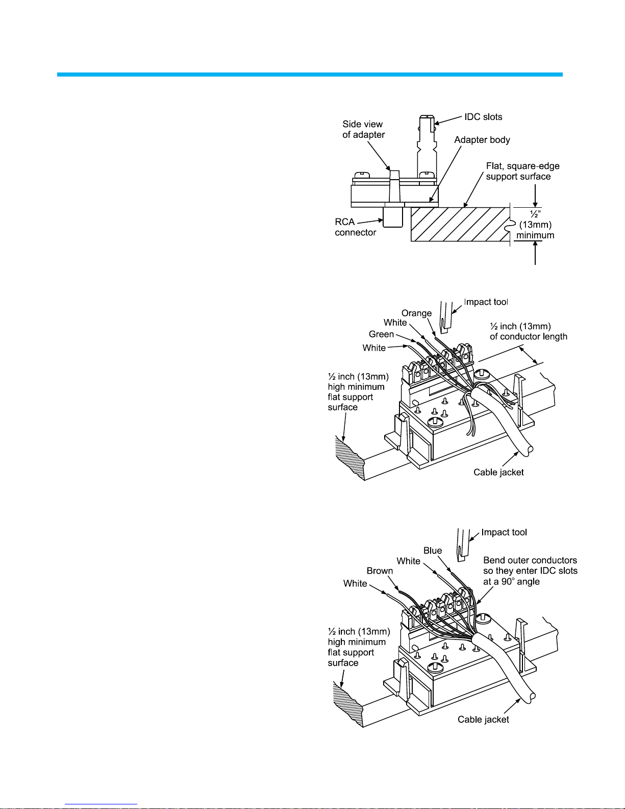
2. Locate a block of wood or other suitable flat,
square-edge surface, which is a minimum of 1/2
inch (13mm) thic k, and position the adapter on it as
shown before connecting wires.
Important: Do not exert force on the rear of the
adapter without first resting the adapter body on a
supporting surface, so as to prevent damage to
RCA connectors on the front.
3. Untwist the orange/white pair and green/white pair
first and place both pairs of conductors in the
appropriately color-coded IDC slots. There should
be approximately 1/2 inch (13mm) of conductor
length from the edge of the IDC slot to the cable
jacket.
Note: Ins erting these pairs firs t will help center the
jacketed cable at the rear of the adapter. This is
important for placing caps over slots and in
preventing conductor pullout from the IDC slot.
www.commscope.com
4. Seat the wires into the IDC slots using an impact
tool with M110 blade on LO-impact setting. Use the
cutting edge of the blade to trim excess wire flush
with 110 block.
5. Untwist the blue/white pair and brown/white pair
and place both pairs of conductors in the
appropriately color-coded IDC slots.
6. Bend the outer conductors evenly so they enter the
IDC slots at a 90° angle.
7. Seat the wires into the IDC slots using an impact
tool with M110 blade on LO-impact setting. Use the
cutting edge of the blade to trim excess wire flush
with 110 block.
Page 2 of 3
Page 3

www.commscope.com
860336478
8. Place two caps over terminated conductors and
bend the conductors as shown before inserting the
adapter into a faceplate.
Snap Adapte r i nto Fl exible Faceplate
Note: Adapters should be inserted from center to
outside on duplex frame (desc ribed here), but may
be snapped-in from either left or right side on
single frame
Issue 4, December 2012
1. Locate adapter so that latch lines up with one of
three tapered sections on edge of duplex frame.
2. Position edge of adapter into frame on center
section.
Push in on outside edge of adapter until latch
snaps into frame.
Page 3 of 3
 Loading...