


USE and MAINTENANCE MANUAL
-Steam sterilizer-
FOREWORD
This manual must be considered an integral part of the sterilizer, and must always be available to users. The manual must always accompany the sterilizer, even if it is sold to another user.
All operators are responsible for reading this manual and for strictly complying with the instructions and information it provides. COMINOX is not liable for any damage to people, things, or the sterilizer itself in the event that the operator fails to comply with the conditions described in the manual.
These instructions are confidential and the customer may not disclose any information to third parties. Further, this documentation and its attachments may not be tampered with or modified, copied, or ceded to third parties without authorization from COMINOX.
2

Table of contents
TABLE OF CONTENTS
TABLE OF CONTENTS........................................................................................................................ |
3 |
Reference index .............................................................................................................................. |
6 |
Graphic representation of references Mod. 18 ......................................................................... |
7 |
Graphic representation of references Mod. 24 ......................................................................... |
8 |
INTRODUCTION................................................................................................................................ |
9 |
GENERAL SUPPLY CONDITIONS.......................................................................................................... |
9 |
PURPOSE OF THE DOCUMENT .......................................................................................................... |
10 |
EQUIPMENT.......................................................................................................................................... |
10 |
OPERATING USE.................................................................................................................................. |
11 |
Table of cycles/sterilizable material 18B - 18BHD..................................................................... |
12 |
Table of cycles/sterilizable material 18S .................................................................................... |
13 |
Table of cycles/sterilizable material 24B - 24BHD..................................................................... |
13 |
TECHNICAL SPECIFICATIONS........................................................................................................ |
15 |
Technical specifications table 18 ............................................................................................... |
15 |
Technical specifications table 24 .............................................................................................. |
16 |
REFERENCE STANDARDS.................................................................................................................... |
16 |
DIMENSIONS........................................................................................................................................ |
17 |
General dimensions ...................................................................................................................... |
17 |
Dimensions required when the unit is to be built-in ................................................................. |
17 |
GENERAL SAFETY CONDITIONS .................................................................................................... |
18 |
Thermal danger ................................................................................................................................. |
18 |
Noise .................................................................................................................................................... |
18 |
Environmental conditions and risks................................................................................................. |
19 |
Residual risks table......................................................................................................................... |
19 |
TRANSPORTATION AND PACKAGING.......................................................................................... |
20 |
Unpacking and cleaning the components.................................................................................. |
20 |
Storage ................................................................................................................................................ |
21 |
INSTALLATION ................................................................................................................................ |
22 |
GENERAL CONDITIONS ..................................................................................................................... |
22 |
Arrangement...................................................................................................................................... |
22 |
|
3 |
Table of contents |
|
|
|
||
|
|
|
|
||
CONNECTIONS ................................................................................................................................... |
|
|
23 |
||
Electrical connections .................................................................................................................. |
23 |
||||
Water connection ......................................................................................................................... |
23 |
||||
Water supply table........................................................................................................................ |
24 |
||||
MANUALLY FILL CLEAN WATER TANK .............................................................................................. |
25 |
||||
MANUALLY DRAIN TANKS.................................................................................................................. |
25 |
||||
PREPARING FOR BUILT-IN INSTALLATION ......................................................................................... |
25 |
||||
OPERATION .................................................................................................................................... |
|
|
26 |
||
SWITCH-ON ......................................................................................................................................... |
|
|
26 |
||
STAND BY ............................................................................................................................................. |
|
|
|
28 |
|
MENU.................................................................................................................................................... |
|
|
|
29 |
|
1. |
Cycle Menu............................................................................................................................ |
30 |
|||
2. |
Main Settings Menu............................................................................................................... |
30 |
|||
|
2.1 |
Language ....................................................................................................................... |
31 |
||
|
2.2 |
Date and Time ............................................................................................................... |
31 |
||
|
2.3 |
Button Sound.................................................................................................................. |
31 |
||
|
2.4 |
Self-stop........................................................................................................................... |
31 |
||
|
2.5 |
Self-filling ......................................................................................................................... |
32 |
||
|
2.6 |
Printer............................................................................................................................... |
32 |
||
|
2.7 |
Cycle Recording ........................................................................................................... |
32 |
||
|
2.8 |
Data Logging................................................................................................................. |
32 |
||
3. |
Advanced Menu Functions................................................................................................. |
33 |
|||
|
3.1 |
Prog. SPECIAL ................................................................................................................. |
33 |
||
|
3.2 |
Programmed start ......................................................................................................... |
34 |
||
|
3.3 |
Hollow Loads .................................................................................................................. |
35 |
||
|
3.4a |
Change sec. Code....................................................................................................... |
36 |
||
|
3.4b |
SterilCard Option........................................................................................................... |
37 |
||
|
3.4b.1 |
Create User ............................................................................................................ |
37 |
||
|
3.4b.2 |
Delete User ............................................................................................................. |
40 |
||
|
3.4b.3 |
Enable User............................................................................................................. |
41 |
||
4. |
Cycle Records Menu ............................................................................................................ |
42 |
|||
5. |
Maintenance Menu.............................................................................................................. |
43 |
|||
|
5.1 |
Items ................................................................................................................................ |
43 |
||
|
5.2 |
Save Maintenance ....................................................................................................... |
44 |
||
INFORMATION in STAND BY .............................................................................................................. |
45 |
||||
STARTING the CYCLE ......................................................................................................................... |
45 |
||||
STOP the CYCLE ............................................................................................................................. |
46 |
||||
EVENTS in the CYCLE ..................................................................................................................... |
47 |
||||
INFORMATION about the CYCLE ................................................................................................ |
48 |
||||
PLOT of the CYCLE......................................................................................................................... |
48 |
||||
CONTROL TESTS |
.................................................................................................................................. |
|
49 |
||
Bowie & Dick test ........................................................................................................................... |
49 |
||||
Vacuum test ................................................................................................................................... |
|
|
49 |
||
Helix test |
.......................................................................................................................................... |
|
|
51 |
|
4

|
Table of contents |
Printer ................................................................................................................................................... |
51 |
Cycle Recording on SterilCard ....................................................................................................... |
52 |
INDICATORS................................................................................................................................... |
54 |
ALARMS.......................................................................................................................................... |
56 |
List of alarm codes ............................................................................................................................ |
61 |
MAINTENANCE .............................................................................................................................. |
62 |
GENERAL CONDITIONS .................................................................................................................... |
62 |
Cleaning.......................................................................................................................................... |
62 |
Filters................................................................................................................................................. |
63 |
Checks............................................................................................................................................. |
63 |
Fuses................................................................................................................................................. |
63 |
To calibrate the fuses 32, refer to the label plate inside the door 18....................................... |
63 |
STORAGE AND DISPOSAL.................................................................................................................. |
64 |
Machine storage or long-term disuse....................................................................................... |
64 |
Disposal and Scrapping .............................................................................................................. |
64 |
Scheduled service table .................................................................................................................. |
65 |
APPENDIX 1: GRAPHICS 18 B – 18 BHD / 24B – 24 BHD ............................................................. |
66 |
APPENDIX 2: GRAPHICS 18 S...................................................................................................... |
67 |
5

Table of contents
Reference index
01: tray handle 02: waste pipe 03: power cable 04: tray
05: metering funnel 06: SterilCard
07: pouch holders
08: support for 5 trays or 3 cassettes
09:chamber
10:clean water tank
11:waste water recovery tank
12:safety valve
13:main switch
14:filler
15:air sterilization filter
16:door
17:safety thermostat
18:print door
19:coil covering grid
20:waste filter
21:chamber probe
22:adjustable feet
23:lifting straps
24:clean water tap
25:waste water tap
26:printer
27:level testing pipe
28:grid seal
29:auto water fill
30:direct drain
31:chamber seal
32:fuses
6
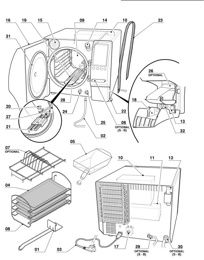
Table of contents
Graphic representation of references Mod. 18
7

Table of contents
Graphic representation of references Mod. 24
8

Introduction
INTRODUCTION
GENERAL SUPPLY CONDITIONS
COMINOX declares that the sterilizer complies with the standards and regulations in force in the European Economic Community and issues the attached DECLARATION OF CONFORMITY.
COMINOX will repair any manufacturing defects that arise within 24 months from the time the sterilizer is installed (refer to the Guarantee). The chamber 09 is guaranteed for 10 years.
The customer must use original spare parts only and fit them according to their intended use.
Responsibility for commercial components lies with their manufacturers.
COMINOX is not liable for defects or malfunctions deriving from improper use of the sterilizer, changes that occur during transportation, or those caused by specific environmental conditions, lack of maintenance or maintenance conducted improperly, or problems due to tampering or incorrect repairs.
COMINOX declines all responsibility if the sterilizer is not installed properly or if it is not installed by duly trained and qualified personnel.
COMINOX IS NOT responsible for the disposal of the products required for the transport or operation of the sterilizer or for production materials: packaging, waste water, lubricants, etc. The customer is individually responsible, under the specific regulations and standards in force in each installation country, for disposing of any substances that are potentially harmful to the environment.
The same precautions apply to scrapping the sterilizer.
9

Introduction
PURPOSE OF THE DOCUMENT
This Use and Maintenance Manual aims to provide the operator with a useful guide for:
•understanding the correct procedures for installing the sterilizer;
•explaining the various SterilClave functions;
•ensuring optimal use of the sterilizer;
•operating in complete safety;
•conducting the maintenance required for proper upkeep of the sterilizer.
EQUIPMENT
In addition to this Use and Maintenance Manual, each sterilizer is supplied with a Guarantee Certificate and the EC Declaration of Conformity.
The Cominox SterilClave sterilizer also includes the following accessories:
|
# |
18S |
18B - 24B |
18BHD - 24BHD |
Tray handle 01 |
1 |
• |
• |
• |
Waste pipe 02 |
1 |
• |
• |
• |
Level testing pipe27 |
1 |
• |
• |
• |
Grid seal 28 |
1 |
• |
• |
• |
Power cable 03 |
1 |
• |
• |
• |
Trays 04 |
3 |
• |
• |
• |
Pouch holders 07 |
1 |
optional |
optional |
optional |
Support for 5 trays or 3 cassettes 08 |
1 |
• |
• |
• |
Metering funnel 05 with cap |
1 |
• |
• |
• |
Administrator and User SterilCards 06 |
2 |
optional |
optional |
• |
Printer 26 |
1 |
optional |
optional |
optional |
Auto water fill 29 |
1 |
optional |
optional |
• |
Direct drain 30 |
1 |
optional |
optional |
• |
|
|
|
• Supplied as standard |
|
10
Introduction
OPERATING USE
Under no circumstances should the sterilizer or its parts be used for any purpose other than those described below.
The sterilizer was designed to:
STERILIZE
AUTOCLAVABLE SURGICAL, DIAGNOSTIC OR MEDICAL INSTRUMENTS for example: SCISSORS, SCALPEL, GAUZE, FABRICS
Various types of materials can be sterilized, such as: stainless steel, glass, rubber, plastic, cotton, fabrics in general.
!Check that that the product to be sterilized can withstand a temperature higher than the temperature of the programmed cycle.
Observe the normal usage conditions described. COMINOX guarantees that the maximum measurable temperature in chamber 09 will be: PROGRAMMED STERILIZATION TEMPERATURE +3°C (standard EN 13060: minimum temperature = sterilization temperature -0°C; maximum temperature = sterilization temperature +4 °C).
The EN 13060 standard distinguishes various types of load depending on the material to be sterilized: solid tools (e.g. scalpels), hollow tools of type A or type B (e.g. surgical extraction cannula) and porous loads (e.g. fabrics and gauzes). This division should guide the operator in selecting the sterilization cycle (see Table of cycles/sterilizable material).
Strictly comply with the sterilization instructions and information specified by the manufacturer for any material to be sterilized.
!additivedry. -free water and dried. The support for the load must also be perfectlyInstruments and fabrics to be sterilized MUST be carefully washed, rinsed with
Comply with the maximum total load weight (see Table of cycles/sterilizable material). Use the load support system supplied by COMINOX (see Preparation of the load to be sterilized). Use of load supports other than the standard support provided may compromise the steam penetration and drying performance confirmed during approval tests.
Follow instructions concerning correct packaging, and only use packaging materials compliant with standard EN868.
The sterilizer may NOT be operated or installed in areas in which gas or any other ! explosive volatile substance is present.
11
|
Introduction |
|
|
|
|
|
|
|
|
|
|
|
|
|
|
|
|
|
|||||
|
Table of cycles/sterilizable material 18B - 18BHD |
|
|
|
|
||||||
|
|
|
|
|
|
|
|
|
|
|
|
|
|
121 |
134 |
|
134 |
121 |
134 |
134 PRION |
BOWIE & |
VACUUM |
|
|
|
UN- |
UN- |
POROUS / |
POROUS / |
||||||
|
|
WRAPPED |
WRAPPED |
WRAPPED |
HOLLOW |
HOLLOW |
|
DICK TEST |
TEST |
||
|
|
|
|
|
|
||||||
Type according to |
N |
N |
S1 |
B |
B |
B |
|
|
|||
EN 13060 |
|
|
|||||||||
|
|
|
|
|
|
|
|
|
|||
Temperature |
121°C |
134°C |
134°C |
121°C |
134°C |
134°C |
134°C |
- |
|||
Pressure |
2.1 bar |
3.1 bar |
3.1 bar |
2.1 bar |
3.1 bar |
3.1 bar |
3.1 bar |
- |
|||
Duration of |
15' |
4' |
|
4' |
15' |
4' |
18' |
3.5' |
- |
||
sterilization phase |
|
||||||||||
|
|
|
|
|
|
|
|
|
|||
Drying |
no |
no |
20' |
20' |
20' |
20' |
no |
no |
|||
Total duration |
23' - 30' |
13' - 21' |
|
37' - 48' |
57' - 77' |
49' - 69' |
63' – 85' |
25' |
20' |
||
(minimum - maximum) |
|
||||||||||
|
|
|
|
|
|
|
|
|
|||
Load: |
|
|
|
|
|
|
|
|
|
||
|
solid |
yes |
yes |
yes |
yes |
yes |
yes |
|
|
||
|
porous |
no |
no |
no |
yes |
yes |
yes |
empty |
empty |
||
|
hollow A |
no |
no |
no |
yes |
yes |
yes |
chamber |
chamber |
||
|
hollow b |
no |
no |
no |
yes |
yes |
yes |
|
|
||
Packaging: |
|
|
|
|
|
|
|
|
|
||
|
not packaged |
yes |
yes |
yes |
yes |
yes |
yes |
empty |
empty |
||
|
single pack |
no |
no |
yes |
yes |
yes |
yes |
||||
|
chamber |
chamber |
|||||||||
|
double pack |
no |
no |
no |
yes |
yes |
yes |
||||
|
|
|
|||||||||
Maximum load weight |
5 Kg |
5 Kg |
3 Kg |
2.5 - 1.5 Kg |
2.5 - 1.5 Kg |
2.5 - 1.5 Kg |
- |
- |
|||
(solid/hollow - porous) |
|||||||||||
|
|
|
|
|
|
|
|
|
|||
12

|
|
|
|
|
|
|
IntroductionIntroduzione |
||
Table of cycles/sterilizable material 18S |
|
|
|
|
|
||||
|
|
|
|
|
|
|
|
|
|
|
121 |
134 |
134 |
121 |
134 |
134 PRION |
BOWIE & |
VACUUM |
|
|
UN- |
UN- |
POROUS/ |
POROUS/ |
|||||
|
WRAPPED |
WRAPPED |
WRAPPED |
HOLLOW |
HOLLOW |
|
DICK TEST |
TEST |
|
|
|
|
|
|
|||||
Type according to |
N |
N |
S1 |
S2 |
S2 |
S2 |
|
|
|
EN 13060 |
|
|
|||||||
|
|
|
|
|
|
|
|
||
Temperature |
121°C |
134°C |
134°C |
121°C |
134°C |
134°C |
134°C |
- |
|
Pressure |
2.1 bar |
3.1 bar |
3.1 bar |
2.1 bar |
3.1 bar |
3.1 bar |
3.1 bar |
- |
|
Duration of |
15' |
4' |
4' |
15' |
4' |
18' |
3,5' |
- |
|
sterilization phase |
|||||||||
|
|
|
|
|
|
|
|
||
Drying |
no |
no |
25' |
25' |
25' |
25' |
no |
no |
|
Total duration |
24' - 29' |
14' - 19' |
44' - 54' |
59' - 70' |
50' - 59' |
64' - 74' |
25' |
20' |
|
(minimum - maximum) |
|||||||||
|
|
|
|
|
|
|
|
||
Load: |
|
|
|
|
|
|
|
|
|
solid |
yes |
yes |
yes |
yes |
yes |
yes |
|
|
|
porous |
no |
no |
no |
yes |
yes |
yes |
empty |
empty |
|
hollow A |
no |
no |
no |
no |
no |
no |
chamber |
chamber |
|
hollow b |
no |
no |
no |
yes |
yes |
yes |
|
|
|
Packaging: |
|
|
|
|
|
|
|
|
|
not packaged |
yes |
yes |
yes |
yes |
yes |
yes |
empty |
empty |
|
single pack |
no |
no |
yes |
yes |
yes |
yes |
|||
chamber |
chamber |
||||||||
double pack |
no |
no |
no |
no |
no |
no |
|||
|
|
||||||||
Maximum load weight |
5 Kg |
5 Kg |
3 Kg |
2.5 - 1 Kg |
2.5 - 1 Kg |
2.5 - 1 Kg |
- |
- |
|
(solid/hollow - porous) |
|||||||||
|
|
|
|
|
|
|
|
||
Table of cycles/sterilizable material 24B - 24BHD |
|
|
|
|
|||||
|
|
|
|
|
|
|
|
|
|
|
121 |
134 |
134 |
121 |
134 |
134 PRION |
BOWIE & |
VACUUM |
|
|
UN- |
UN- |
POROUS/ |
POROUS/ |
|||||
|
WRAPPED |
WRAPPED |
WRAPPED |
HOLLOW |
HOLLOW |
|
DICK TEST |
TEST |
|
Type according to |
N |
N |
S1 |
B |
B |
B |
|
|
|
EN 13060 |
|
|
|||||||
|
|
|
|
|
|
|
|
||
Temperature |
121°C |
134°C |
134°C |
121°C |
134°C |
134°C |
134°C |
- |
|
Pressure |
2.1 bar |
3.1 bar |
3.1 bar |
2.1 bar |
3.1 bar |
3.1 bar |
3.1 bar |
- |
|
Duration of |
15' |
4' |
4' |
15' |
4' |
18' |
3,5' |
- |
|
sterilization phase |
|||||||||
|
|
|
|
|
|
|
|
||
Drying |
no |
no |
20' |
20' |
20' |
20' |
no |
no |
|
Total duration |
21' - 28' |
11' - 19' |
37' - 49' |
60' - 79' |
49' - 73' |
66' - 88' |
25' |
20' |
|
(minimum - maximum) |
|||||||||
|
|
|
|
|
|
|
|
||
Load: |
|
|
|
|
|
|
|
|
|
solid |
yes |
yes |
yes |
yes |
yes |
yes |
|
|
|
porous |
no |
no |
no |
yes |
yes |
yes |
empty |
empty |
|
hollow A |
no |
no |
no |
yes |
yes |
yes |
chamber |
chamber |
|
hollow b |
no |
no |
no |
yes |
yes |
yes |
|
|
|
Packaging: |
|
|
|
|
|
|
|
|
|
not packaged |
yes |
yes |
yes |
yes |
yes |
yes |
empty |
empty |
|
single pack |
no |
no |
yes |
yes |
yes |
yes |
|||
chamber |
chamber |
||||||||
double pack |
no |
no |
no |
yes |
yes |
yes |
|||
|
|
||||||||
Maximum load weight |
7.5 Kg |
7.5 Kg |
4 Kg |
3.7 - 2.2 Kg |
3.7 - 2.2 Kg |
3.7 - 2.2 Kg |
- |
- |
|
(solid/hollow - porous) |
|||||||||
|
|
|
|
|
|
|
|
||
13

Introduction
NOTE
CYCLE N: sterilization cycle for solid instruments, unpackaged only.
CYCLE S1: sterilization cycle for solid instruments, packaged or unpackaged.
CYCLE S2: sterilization cycle for solid instruments, porous loads, and hollow loads type B, packaged or unpackaged.
CYCLE B: sterilization cycle for solid instruments, porous loads, and hollow loads type A or B, packaged or unpackaged; double packaging is also permitted.
TYPE A HOLLOW LOADS: Instruments with an open cavity on one side only, where the length to cavity diameter ratio is greater than or equal to 1 and less than or equal to 750 (1 ≤ L/D ≤ 750), and where the length of the cavity is no longer than 1500 mm (L ≤ 1500 mm). Alternatively, instruments with an open cavity on both sides, whose length to cavity diameter ratio is greater than or equal to 2 and less than or equal to 1500 (2 ≤ L/D ≤ 1500), and where the length of the cavity is no longer than 3000 mm (L ≤ 3000 mm).
TYPE B HOLLOW LOADS: Instruments with an open cavity on one side only, where the length to cavity diameter ratio is greater than or equal to 1 and less than or equal to 5 (1 ≤ L/D ≤ 5), and where the diameter of the cavity is greater than or equal to 5 mm (D ≥ 5 mm). Alternatively, instruments with an open cavity on both sides, whose length to cavity diameter ratio is greater than or equal to 2 and less than or equal to 10 (2 ≤ L/D ≤ 10), and where the diameter of the cavity is greater than or equal to 5 mm (D ≥ 5 mm).
MAXIMUM LOAD WEIGHT: the maximum weight permitted for each load category described, including the load support system and its packaging.
TOTAL MAXIMUM DURATION: the total time the sterilizer requires to run a complete cycle, calculated from cold startup (room temperature) and maximum load.
TOTAL MINIMUM DURATION: the total time the sterilizer requires to run a complete cycle, including hot startup (one cycle after the other) and minimum load (load support only).
14

Technical specifications
TECHNICAL SPECIFICATIONS
Technical specifications table 18
|
U.M. |
S |
B |
BHD |
|
Steam generation |
|
in chamber |
in chamber |
in chamber |
|
Chamber capacity |
l |
|
17,15 |
|
|
Clean water tank capacity |
l |
|
2,1 |
|
|
Waste water recovery tank capacity |
l |
|
2,1 |
|
|
Water consumption per cycle |
|
|
|
|
|
(minimum/maximum) |
cm³ |
180 - 500 |
210 - 700 |
210 - 700 |
|
Minimum water load |
cm³ |
500 |
700 |
700 |
|
Maximum flow discharge rate (direct) |
cm³/s |
|
30 |
|
|
Maximum discharge temperature (direct) |
°C |
|
83 |
|
|
Absolute operating pressure (maximum) |
kPa |
|
331 |
|
|
Electrical voltage and frequency |
V - Hz |
230 – 50/60 (single-phase AC) |
|||
Maximum allowed voltage fluctuations |
% |
|
±10 |
|
|
Absorbed maximum power |
W |
|
2000 |
|
|
Heat emission |
J/h |
|
0,3 |
|
|
Detected noise level in work areas under |
dB(A) - dB(C) |
|
55.7 - 62.7 |
|
|
suitable conditions (medium-peak) |
|
|
|||
|
|
|
|
||
Weight (mass) |
kg |
48,7 |
51 |
51 |
|
Weight per support area with full tank and |
kg/cm² |
1,16 |
1,2 |
1,2 |
|
maximum load |
|||||
|
|
|
|
||
Room temperature allowed |
°C |
|
from 15 to 40 |
|
|
Maximum relative humidity allowed |
% |
|
85 |
|
|
Maximum altitude allowed with standard safety |
m asl |
1500 (2000 with replacement of the valve) |
|||
valve |
|||||
|
|
|
|
||
Conditional connections: |
Ω |
|
0.139+j0.087 |
|
|
maximum impedance |
|
|
|||
|
|
|
|
||
15

Technical specifications
Technical specifications table 24
|
U.M. |
B |
|
BHD |
|
Steam generation |
|
in chamber |
|
in chamber |
|
Chamber capacity |
l |
|
23,15 |
||
Clean water tank capacity |
l |
|
3,1 |
||
Waste water recovery tank capacity |
l |
|
3.1 |
||
Water consumption per cycle |
|
|
|
|
|
(minimum/maximum) |
cm³ |
420-1040 |
|
420-1190 |
|
Minimum water load |
cm³ |
1040 |
|
1190 |
|
Maximum flow discharge rate (direct) |
cm³/s |
|
30 |
||
Maximum discharge temperature (direct) |
°C |
|
83 |
||
Absolute operating pressure (maximum) |
kPa |
|
331 |
||
Electrical voltage and frequency |
V - Hz |
230 – 50/60 (single-phase AC) |
|||
Maximum allowed voltage fluctuations |
% |
|
±10 |
||
Absorbed maximum power |
W |
|
2800 |
||
Heat emission |
J/h |
|
0.3 |
||
Detected noise level in work areas under |
dB(A) - dB(C) |
|
56 - 63 |
||
suitable conditions (medium-peak) |
|
||||
|
|
|
|
||
Weight (mass) |
kg |
63 |
|
68 |
|
Weight per support area with full tank and |
kg/cm² |
1.53 |
|
1.63 |
|
maximum load |
|
||||
|
|
|
|
||
Room temperature allowed |
°C |
|
from 15 to 40 |
||
Maximum relative humidity allowed |
% |
|
85 |
||
Maximum altitude allowed with standard safety |
m asl |
1500 (2000 with replacement of the valve) |
|||
valve |
|||||
|
|
|
|
||
Conditional connections: |
Ω |
|
0.153+j00.096 |
||
maximum impedance |
|
||||
|
|
|
|
||
REFERENCE STANDARDS
SterilClave sterilizers were conceived and designed in conformity with the following directives and standards:
Directives
97/23/CE Pressure equipment 93/42/EEC Medical devices (class II a)
89/336/CEE Electromagnetic compatibility (and subsequent updates) 73/23/CEE Low voltage (and subsequent updates)
Standards
EN 13060 Small steam sterilizers
EN 61010-1 Safety regulations for laboratory devices - Part 1: General regulations
EN 61010-2-040 Safety regulations specific to sterilizers used in the processing of medical material.
EN 61326-1 Electromagnetic compatibility regulations for laboratory devices
16

Technical specifications
DIMENSIONS
General dimensions
|
SterilClave 18 |
SterilClave 24 |
|
A - Width |
445 |
445 |
|
B - Height |
390 |
470 |
|
C - Depth |
640 |
700 |
|
D - Unit depth with door |
880 |
940 |
|
open |
|||
|
|
Dimensions required when the unit is to be built-in
|
SterilClave 18 |
SterilClave 24 |
E - Width |
450 |
450 |
F - Height |
395 |
475 |
G - Depth |
560 |
620 |
!remove the adjustable feet.
Leave approximately 20 mm of space for rear ventilation. Built-in units require an
additional 20 mm between the unit and the wall. In this case, the unit must have a rear opening for ventilation, as illustrated.NEVER place the machine on soft surfaces (such as cloth or foam) and never
Usable space dimensions
|
SterilClave 18 |
SterilClave 24 |
H - Width |
185 |
185 |
I - Height |
150 |
150 |
L - Depth |
285 |
420 |
17

General safety conditions
GENERAL SAFETY CONDITIONS
•Switch off the sterilizer at the main switch 13 and disconnect the power cable 03 before conducting any operations apart from those in the normal operations cycle.
•The main power supply must be properly grounded.
•It is essential that operators are properly educated. It is therefore compulsory for them to read and comply with the technical information provided in the manual and attached documentation. The use of unqualified personnel is strictly prohibited.
•Personnel who operate the sterilizer must always use the appropriate individual protective devices: gloves for sharp or pointed objects and heated elements, and the special tray handle for emptying the chamber.
•Avoid any temporary repairs: repairs must be performed exclusively with original spare parts, and these must be installed by an authorized technician.
•Never remove or dismantle any part from the sterilizer. Only authorized personnel trained in advance by COMINOX may remove the exterior protective cover and access the interior parts.
•Labeling plates on the unit should not be removed, damaged, or dirtied. They must be kept clean and clearly visible.
•Do not use the sterilizer if there are possible defects in its operation.
•The sterilizer should be cleaned using suitable means and detergents that will not damage or corrode any machine components. It is strictly forbidden to clean or wash the sterilizer with jets of water.
•Never place containers of liquids on the sterilizer or the shelves above it. Leakage or spillage on the electric system can cause a short circuit.
•Do not place flammable or toxic materials and products for sterilization in the chamber 09.
•Do not use the sterilizer to process containers that hold fluids, whether they are sealed or not.
•Never lean on the door 16.
The information in this manual does not replace any safety instructions or technical data for installation and operation on the unit itself, nor any safety standards in force in the installation country, or the rules of common sense.
Thermal danger
Interior parts of the door 16 and of the chamber 09 can reach extremely high temperatures.
Never touch the heated surfaces until they have cooled, and always use the appropriate protective gloves. The same applies when a load is to be removed from the sterilization chamber. To remove the trays 04 holding the load, always use the tray handle 01. Never leave the tray handle inside the sterilization chamber.
!When opening the door 16, steam may escape, which could cause burns. Never stand in front of or above the door!
The temperature in the sterilization chamber is controlled by a safety thermostat 17 that intervenes if overheating occurs. The safety thermostat must be reset manually.
Noise
The sound pressure level (noise) detected in suitable work spaces must be lower than 70dB(A).
18

General safety conditions
Environmental conditions and risks
The sterilizer may not be installed in the open or be exposed to unfavourable weather conditions (sun, rain, snow, wind).
!In addition, make sure that there is no electromagnetic interference that could affect the data in the electronic devices.
!The unit is not equipped as standard for operation in environments that present a particular risk of fire or explosion.
COMINOX is not liable for the disposal of materials required for the operation or production of the sterilizer (e.g.: plastic packaging or potentially contaminated waste water...). The client must personally provide for the removal of any substances that are potentially harmful to the environment in compliance with regulations in force in the country of installation.
The same precautions apply to scrapping the sterilizer.
The sterilizer was designed in compliance with best practices concerning energy conservation, preventing needless waste.
Residual risks table
RISK ANALYSIS AND DESCRIPTION |
SUGGESTED REMEDY |
|
|||
Losses or leaks with risks of slipping, short |
Carefully clean the workplace. |
|
|||
circuit or pollution. |
|
||||
|
|
|
|
||
Drainage of waste water contaminated by |
Dispose of according to the regulations in |
||||
viruses, bacteria, or pathogenic micro- |
|||||
force. |
|
|
|
||
organisms. |
|
|
|
||
|
|
|
|
||
Escaping steam and/or gas fumes when |
Always carefully |
check |
whether the |
load |
|
complies with |
cycle |
temperatures, |
and |
||
opening the door 16. |
|||||
open the door with caution. |
|
||||
|
|
||||
Excessively hot surfaces, especially in the |
Wear protective gloves and/or never touch |
||||
sterilization chamber 09 and on certain |
any internal components unless duly |
||||
solenoid valves or internal components. |
AUTHORIZED. |
|
|
|
|
The chamber seal is hermetic even when |
Do not place plants or animals inside the |
||||
the unit is switched off; plants and animals |
chamber. |
|
|
|
|
cannot survive inside the machine. |
|
|
|
|
|
Poor cleaning or scratching of label plates |
Clean instruments and label plates carefully |
||||
and/or instrumentation can lead to mistakes |
with the appropriate products. |
|
|||
and consequent dangers. |
|
|
|
|
|
Poor training of personnel. |
Request an additional training course from |
||||
COMINOX. |
|
|
|
||
|
|
|
|
||
19

Transportation and packaging
TRANSPORTATION AND PACKAGING
During transport, the sterilizer is protected by a cardboard box.
Lifting and transportation are to be carried out by qualified personnel only.
Weights and dimensions of occupied space are provided in the DIMENSIONS chapter and in the Technical specifications table.
!The packed sterilizer must be lifted after being fitted onto the special pallet, and only using forklifts.Lifting means should not damage or compromise the operation of the sterilizer.
Transportation of the sterilizer, particularly by road, must be conducted using means of transportation that can adequately protect the components (especially electronic components) against violent knocks, humidity, vibrations, and so on.
The sterilizer may be transported only after fully emptying the clean water tank 10 ! and the waste water recovery tank 11.
COMINOX does not accept sterilizers for repair if they have full tanks (see Chap. MANUALLY DRAIN TANKS).
Very heavy items or equipment (heavier than 30 kg) must only be moved or lifted using appropriate lifting devices.
At least two people are required for manual lifting, using the special lifting straps 23 provided and following the correct procedures as specified by current regulations.
!Never lift or move the sterilizer using the door 16 or holding onto other plastic parts.
Unpacking and cleaning the components
!adhesive tape, straps, ropes, etc.) can cut and/or injure if not carefully handled.Remember that packaging (wood, nails, paper, cellophane, metal staples,
They should be removed using appropriate means and not left within reach of unauthorized persons (especially children). The same applies to any device used to remove packaging (scissors, hammers, tongs, knives, etc.).
Packaging components must be removed and disposed of according to the regulations in force in each country.
You are advised to retain the packaging and the lifting straps 23 for possible moves in the future.
When opening the package, the first thing to do is check all the pieces and parts of the sterilizer. Check that all components required are present and in perfect condition (see SUPPLY CONDITIONS).
Remove the supplied parts by opening the door 16 (see OPERATION).
! |
In the event of defects or wear and tear, immediately interrupt any |
operation, |
contact the shipping or forwarding agent, and promptly inform COMINOX. |
|
20
Transportation and packaging
The load support system and the external surface of the sterilizer are sometimes protected by a plastic film: it must be removed before using the machine.
Storage
If the sterilizer will not be used immediately or if will be removed from the installation site, it must be stored in a dry, protected location.
If you wish to cover the machine with plastic sheeting, you must first insert silica gel or other desiccant systems inside the packaging.
!Never place any objects on top of the machine packaging, especially with loads concentrated on protruding feet or screws.
Ideal ambient storage conditions are:
-temperature with empty systems - 25°C + 40°C.
-maximum relative humidity 90%.
21
 Loading...