

Comica CVM-WS60 User Manual
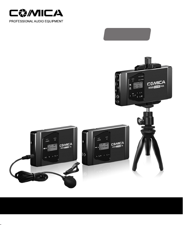
CVM-WS60 COMBO
UHF 1-Trigger-2 Flexible Mini Wireless Microphone
User Manual

Foreword
Thanks for purchasing COMICA WS60 COMBO UHF 1-Trigger-2 flexible mini
wireless microphone;
WS60 is a Flexible Mini wireless microphone with dual-transmitter triggered by
one receiver, which charged by three AAA batteries; It utilizes UHF wireless FM
technology and LCD high-resolution lattice screen, 10-level adjustable volume,
and is integrated into LCF(Low cut filter) ,Stereo / Mono switchable audio mode,
MIC/LINE IN Input Mode Automatically,Smartphone/Camera Mode Switch,Sound
pickup dynamic display and other functions; Meanwhile the high-quality
microphone comes with strong shielding anti-noise performance equals
broadcasting level.
To ensure the smooth use and safety of the product, please carefully read this
instruction before using and properly assemble and operate.
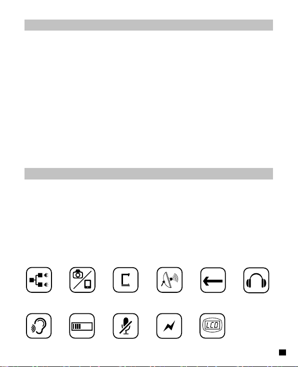
Main Features
. 1-Trigger-2,Universal for Smartphone & Camera
. Built-in Smartphone Holder Design, Flexible and Convenient
. Mini and Compact, Working Distance Up to 60m
(Open Area 60m, 30m in area with obstacle)
. 12 Channels for Multiple Devices Work Together
. M/S Switch, 10-levels Gain Adjustment, Muting Functions
. Real-time Monitor
. AAA Batteries and support external power charging
. Volume Dynamic Monitor
. Lattice LCD Display, High Resolution
60M
1-Trigger-2
Real-time Monitor
Smartphone&Camera
10-Levels
Volume Adjustment
Smartphone Holder
Built-in
Muting Mode
12 channels
Support
External Power
60m Working
Distance
LCD Screen
M/S Switch Universal for
1
Notice
Transmitter should be used more than 20cm from Receiver, when the distance is
less than 20cm, Receiver’s wireless signal receiving part will take protect action to
shut down wireless signal receiving, then audio may be intermittent, which is
normal;
In the case of stereo/mono mode switch, please preset the mode before using to
avoid the transient interference caused by switching during usage;
The product utilizes TRRS-TRRS output cable, different with most TRS-TRS , or
TRS-TRRS output cables in the marketplace, cannot use it universally;
The working distance will be affected by the surrounding environment. Please try
to keep the environment open without interference during usage;
For Smartphone users, please cut off your phone’s WIFI function and set to‘Filght
Mode’ during the usage to avoid incoming call interference.
(It does not support the partial original recording of android systems, the third-party
APP is recommended to be used in this case);
Please keep this product in dry environment;
Do not expose the device in rain or humid environment, otherwise there will be a
danger of short circuit;
Package Contents
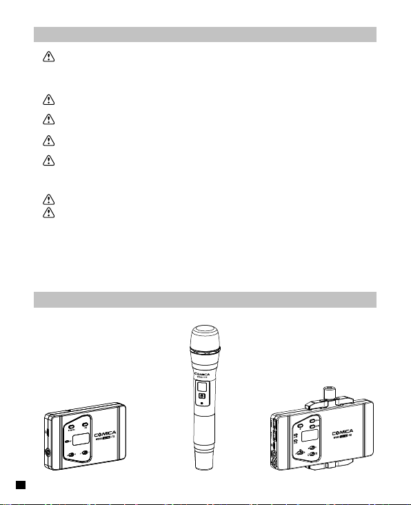
Main Parts:
Lavalier Transmitter(TX)Hand-held Transmitter (HTX
2
)
Receiver(RX
)
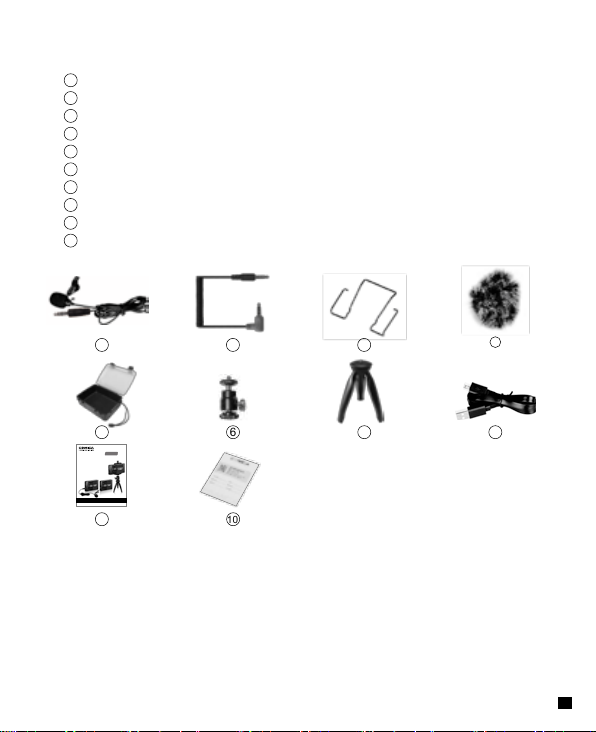
Accessories:
3.5mm Mic Audio Input Cable
1
3.5mm-3.5mm Audio Output Cable
2
Belt Clip
3
Wind Muff
4
Carrying Case
5
6
Ball Head
7
Tabletop Tripod
8
Micro USB Charging Cable
9
User Manual
10
Warranty Card
1
5
CVM-WS60 COMBO
UHF 一拖二无线多功能迷你麦克风
用户使用手册
9
2
6
10
3
7
4
8
3
Components and Instruction
Components
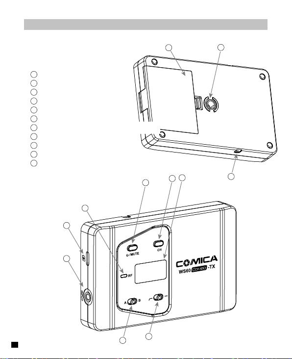
Lavalier Transmitter (TX)
1
1/4 Connecting Hole
2
AAA Battery Tray
3
Belt Clip Connection Hole
4
LCD Screen
5
Channel Selection Switch
6
On-off/Muting Button
7
Matching / Muting Status Light Indicator
8
Type-C External Power Interface
9
MIC/ LINE IN Input Jack
10
Group Switching Button
11
LCF (Low Cut Filter) Switch
7
8
9
2
4
5
6
1
3
11
4
10
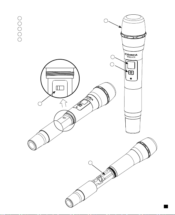
Hand-held Transmitter (HTX)
A B
1
Microphone
2
LCD Display
3
On-off/ RF Adjustment Button
4
Group Switching Button
5
AA Battery Tray
4
A
B
1
2
3
5
5
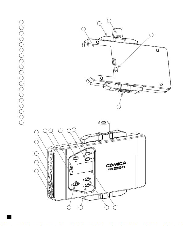
Receiver (RX)
1
1/4 Connecting Hole
2
Locking Screw
3
Smartphone Clamp
4
AAA Battery Tray
5
1/4 Connecting Hole
6
Group A Channel Selection Switch
7
Group B Channel Selection Switch
8
On-off Button
9
Group A Working Status Light Indicator
10
Group B Working Status Light Indicator
11
Group A Volume Adjustment Dial
12
Group B Volume Adjustment Dial
13
Type-C External Power Interface
14
3.5mm Audio Output Jack
15
3.5mm Monitoring Jack
16
Channel Switching Button
17
Smartphone/Camera Switching Button
18
Mono/Stereo Switching Button
19
LCD Display
6
11
12
13
14
15
78910
2
3
4
5
1
16 17 18 19
6
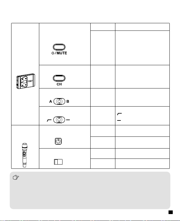
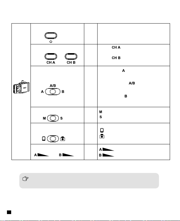
Function Button Instruction
Lavalier
Transmitter
(TX)
Long Press
On-off/Muting Button
Short Press
Power On/OFF
Muting Mode
(The Mute Mode only works
after the screen lighted up)
Channel Selection Switch
Short Press Channel Selection
Group Switching Button
LCF Switch
Push
Push
Left is Group A
Right is Group B
Is Low Cut Mode
Normal Recording
Hand-held
Transmitter
(HTX)
low-cut function will filter out the low-frequency part of the audio source, such as the
chirping and crowd noise, and the main audio source will be more crisp. Low cut
divided into low cut in low range and low cut in high range, low range is to filter out
part of the noise, while high range of low cut filter out all noise. Turn off the low cut
to restore the true, the main source will be more vigorous, but it can be adjusted
according to actual needs.
On-off/ Channel
Selection Button
Channel Selection Button
A B
Long Press Power ON/OFF
Short Press Channel Selection
Push Left Group A
Push Right Group B
7
Receiver
(RX)
On-Off Button
Channel Selection Switch
Group Switching Button
Long
Power ON/OFF
Press
Press is to select Group A`s
Short
Channel
Press
Press is to select Group B`s
Channel
Push left to , Open Group A
only
Push to middle , Open both
Push
Group A and Group B
Push right to , Open Group B
only
Mono/Stereo Switch
Smartphone/Camera
Switching Button
Group Volume Adjustment
At the limitation of external microphone input, Switch to the mono mode
automatically under smartphone mode ,No Stereo Function
8
Push
Turn
Turn
Mono Mode
Stereo Mode
Smartphone Mode
Camera Mode
Group A volume adjustment
Group B volume adjustment
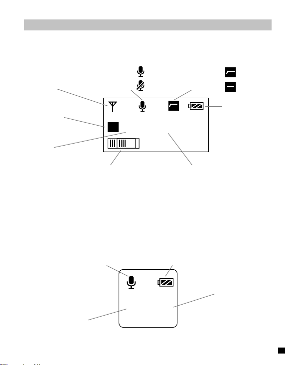
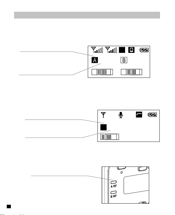
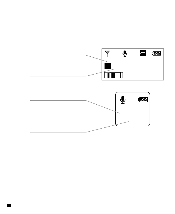
Lavalier Transmitter
Screen Display
Normal Recording
Antenna Icon
Group A/B
Channel
Audio Dynamic Bar Frequency
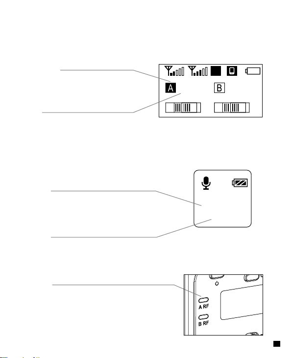
Hand-held Transmitter
Normal Recording Power Indication
Group A/B
Low Cut Filter
Muting
10d
B
Normal Recording
A 11 579.125MHz
A
B
8 8
Power Indication
Channel
9
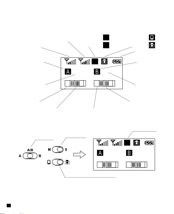
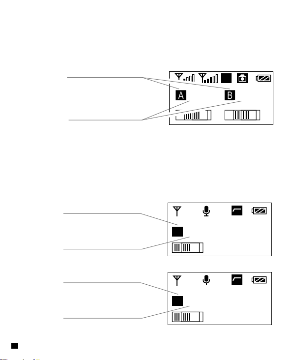
Receiver
Group B Signal Strength
Group A Signal Strength
Group A Group B
Channel A Channel B
Group A Volume
10
A/B Mode
Mono Sound
Stereo Sound
:
M
:
S
S
05
6
M/S Mode
11
9
Group B Audio Receiving Dynamic Bar
Group B VolumeGroup A Audio Receiving Dynamic Bar
05
6
Smartphone / Camera Mode
Smartphone Mode
Camera Mode
Power Indication
Stereo Mode
S
11
9
:
:
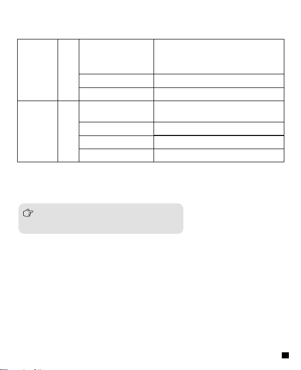
Indicator Light Instruction
Lavalier
Transmitter
(TX)
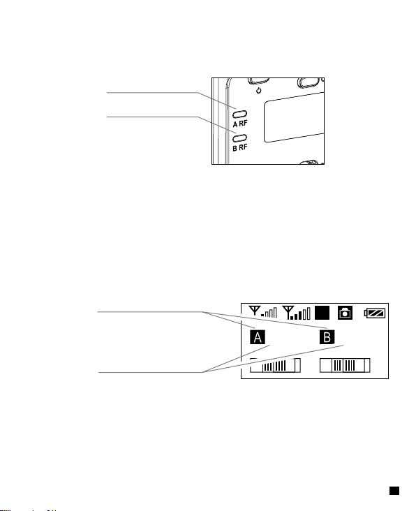
Receiver
(RX)
A RF: Group A working status light indicator
B RF: Group B working status light indicator
Green Light Keeps on
RF
Red Light Keeps on
Red Light Flickers
Green Light Keeps on
A RF
Red Light Flickers
B RF
Green Light Flickers
Red Light Keeps on Group closed
Normal Recording Status
The status works for transmitter only.
(
The receiver can pick up the sound
when channel matched successfully.
Muting Mode
Low- power Reminder
Normal working status after channel
matched successfully
Channel matching is unsuccessful
Low-power Reminder
)
11
The matching steps of Receiver and Transmitter
1. Steps of matching single Lavalier Transmitter with
Receiver
1.1 Switch the Receiver’s Group to “A” OR “B”, and select the
appropriate channel
Switch to Group to “A” OR “B”
M
Select the appropriate channel
05
6
(
Receiver
11
9
)
1.2 Switch the Group of lavalier transmitter to 'A' or 'B' and adjust the
channel of 'A' and 'B' corresponding to the receiver. After above
steps, it will be connected automatically
Switch the corresponding Group
with the Receiver
Switch the corresponding
Channel with the Receiver
10d
B
A 05 573.125MHz
Lavalier Transmitter
(
1.3 When the working status light indicator of Receiver keeps on in
GREEN, it matched successfully
Working Status Light Indicator of
Receiver keeps on in Green
12
Receiver
(
)
)
2. Steps of matching single Hand-held Transmitter
with Receiver
2.1 Switch the Receiver’s Group to “A” OR “B”, and select the
channel Switch to Group to “A” OR “B”
Switch to Group "A" or "B"
M
05
Select the appropriate channel
2.2 Switch the Group of handheld transmitter to 'A' or 'B' and adjust
the channel of 'A' and 'B' corresponding to the receiver. After
above steps, it will be connected automatically
Switch the corresponding Group
with the Receiver
Switch the corresponding Channel
with the Receiver
2.3 When the working status light indicator of Receiver keeps on in
GREEN, it matched successfully
Working Status Light Indicator of
Receiver keeps on in Green
6
(
Hand-held Transmitter
(
Receiver
A
0 5
Receiver
(
11
9
)
)
)
13
3. Steps of matching two Lavalier Transmitters with one
Receiver
3.1 Switch the Receiver’s Group to “A/B” , and select different
channel for different Group
Switch to Group to “A/B”
S
05
Select Different Channel
3.2 Switch the Group of each lavalier transmitter to 'A' or 'B' and
adjust the channel of 'A' and 'B' corresponding to the receiver.
After above steps, it will connected automatically
Switch the corresponding
Group with the Receiver
Switch the corresponding
Channel with the Receiver
Switch the corresponding
Group with the Receiver
Switch the corresponding
Channel with the Receiver
14
6
(
10d
B
A 05 573.125MHz
Lavilier Transmitter A
(
10d
B
B 11 579.125MHz
Lavalier Transmitter B
(
Receiver
11
9
)
)
)
3.3 When the two working status light indicators of Receiver
keeps on in GREEN, it matched successfully
Green Light Keeps on
Green Light Keeps on
Receiver
(
)
4. Steps of matching one Lavalier Transmitter and one
Hand-held Transmitter with Receiver
4.1 Switch the Receiver’s Group to “A/B”, and select different
channel for different Group
Switch to Group to “A/B”
S
Select Different Channel
05
6
Receiver
(
11
9
)
15
4.2 Switch the Group of each transmitter to 'A' or 'B' and adjust the
channel of 'A' and 'B' corresponding to the receiver. After above
steps, it will be connected automatically
Switch the corresponding Group
with the Receiver
10d
B
Switch the corresponding Channel
with the Receiver
Switch the corresponding Group
with the Receiver
A 05 573.125MHz
Lavalier Transmitter
(
B
Switch the corresponding Channel
with the Receiver
4.3 When the two working status light indicators of Receiver keeps
on in GREEN, it matched successfully
16
Hand-held Transmitter
(
)
1 1
)
Installation and Usage
Lavalier Transmitter (TX)
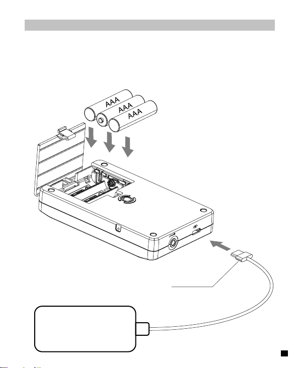
1.Install batteries into the Transmitter’s battery tray according to their
positive and negative electrode; You can also charge by external
power by inserting the Type-C plug into the Type-C Power Interface
Type-C Plug
POWER 5V
17
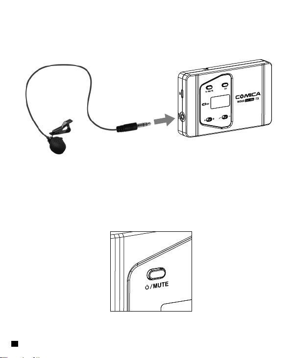
2. Insert the 3.5mm audio input cable into the audio input jack.
3. Long press the On-off Button to open the transmitter.
18
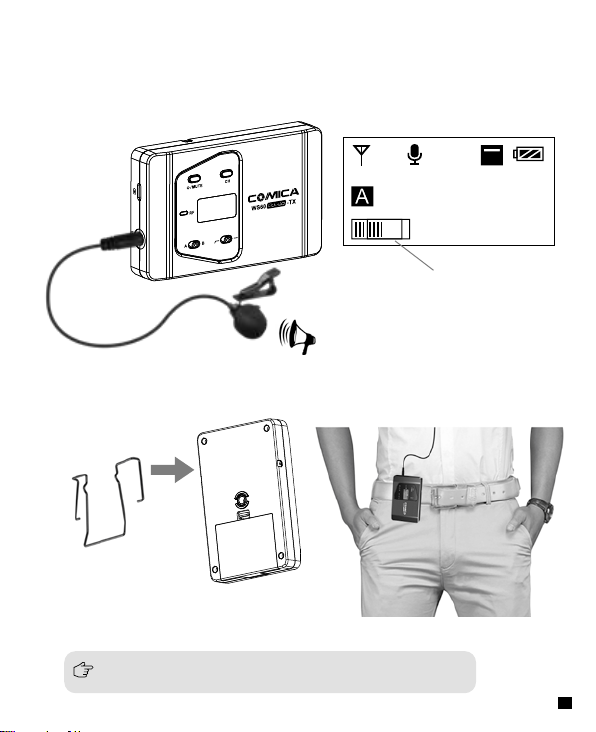
4. Target the Mic to the audio source and check whether the Lavalier
Transmitter is working properly according to the audio display bar
on the screen.
10dB
06 574.125MHz
Audio Dynamic Bar
5. Connect the belt clip to the transmitter through the connection hole
6. It can be used after matched successfully with Receiver
Please refer to the matching steps for channel matching
19
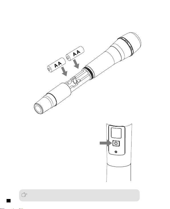
Hand-held Transmitter
1. Install the battery into the hand-held Transmitter’s battery tray
according to their positive and negative electrode
2. Long press the On-off Button to start the hand-held transmitter.
3. It can be used after channel matched successfully with Receiver
20
Please refer to the matching steps for channel matching
 Loading...